1
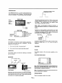
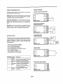
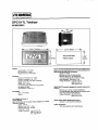
DPCI 0-TL Totalizer
Ml 662/0693
k- 2.95” (74.93mm) -4
I
I
<
T
Recommended
1.57
(39.87mm)
1
POWER
Internal battery: 3 V, lithium
Life expectancy: 5 years +
Replacement Pan: DPClO-BAT
PHYSICAL
Operation Temperature: 0
” - 55°C
Storage Temperature: -20- 70°C
Operating Humidity: 90% Non-condensing
Weight: 2.2 oz. net
Display Size: .43” high
Front Panel Rating: NEMA-4X when mounted
with gasket provided.
Case Material: Cycolac X-17
TOTALIZER
Type: UP counting
Digits: 8
DC COMMON (Terminal 1)
COUNT INPUTS
Input B (Terminal 2) low speed input designed for contact
closures to common
Speed: O-40 Hz
Minimum Low Time: 5msec
Minimum High Time: 20msec
Impedance: 101 kR
Voltage Thresholds: Low 0 to 0.4 V dc
High 2.0 to 28 V dc
Max. High 28 V dc
2.677” (68mm) -+
1.299”
(33mm)
Panel Cutout
I
T
__!I
I
lnputA(Terminal3) highspeedinputrequiringavoltagesource
such ee a current sourcing sensor or a current sinking sensor
used with the provided pull up resistors.
Speed: 0 to 10 kHz
Minimum Low Time: 80 microseconds
Minimum High Time: 20 microseconds
(The above times are with a 0 to 5.0 V swing.)
Input Impedance: 2kS2 above 5 V dc
Voltage Thresholds: Low 0 to 1.2 V dc
High 2.0 to 28 V dc
Max. High 28 V dc
RESET INPUT (Terminal 4) designed for contact closures to dc
common.
Minimum Low: 0.25 to 1 second (maintained)
The required pulse width varies with count speed, scale
factor and number of digits displayed.
Voltage Thresholds: Low 0 to 0.4 V dc
High 2.0 to 28 V dc
FRONT PANEL RESET ENABLE (Terminal 5)
Operation: Level sensitive (maintained)
COUNT ACCURACY
100% when operated within specifications.
INTRODUCTION
Count occurs on this edge of the pulse
(Voltage applied to terminal)
Your OMEGA DPClO-TL is an UP counting totalizer with a
high-contrast eight-digit LCD display. The front-panel reset
/
rl
key can be disabled. A remote-reset terminal is provided.
Plastic
front panel
sealed to meet
NEMA 4X
FRONT VIEW
Terminal 3 is pulled down to common. When a sensor output
supplies voltage to this terminal, one count is registered on
the display. The sourcing signal must supply at least
+2.0 V dc but no more than +28 V dc.
8digit LCD
Display
Note: When a sourcing signal is applied to terminal 3, a
power assist feature of the DPClO-TL extends the life of the
battery.
Ir
Terminal 2 is the low-speed, current-sinking count input
designed to be used with a contact closure to ground. It has
a maximum count speed of 20 Hz. Inputs into this terminal
are counted on the negative-going edge.
REAR VIEW
AST 4 Ml Reset
Contact Closes
Contact Opens
$gjiijjqr
APPLICATIONS
Terminal 2 is pulled up to +3 V dc. When a contact closes,
pulling the voltage down to .4 V dc or less, one count is
registered.
This totalizer is intended for simple totalizing applications.
One count input pulse per item is necessary. The only
decisions to be made are:
1.
Do you use the high or low speed input?
2.
Do you want the front panel reset button active?
RUN MODE
Screens
OPERATION
The totalizer screen is the only screen available on this
model.
The totalizer display has lead-zero blanking. No decimal
point is available.
Front Panel Reset Enable
MOUNTING
Iff flJ
1
Gasket Installed?
t 5 Enable/R
GNDl
t(
Note: The front-panel reset button comes disabled from
the factory. To enable the button, install a jumper wire
from terminal 5 to ground, terminal 1.
Note: The reset terminal on the rear panel is still active when
the front reset button is disabled.
Separate contact and solid state count inputs are provided.
The solid state input (terminal 3) requires a current-sourcing
sensor and can count up to 10 kHz. Inputs into this terminal
are counted on the positive-going edge.
PROGRAM MODE
There is no program mode for this model.
Page 2
WIRING RECOMMENDATIONS
WIRING DIAGRAMS
CONTACT CLOSURE COUNT INPUT
Following these suggestions will increase noise immunity
and extend the life of the product.
Cable: Make the connection between the count source and
the totalizer with a two-conductor shielded cable. Connect
the shield to earth ground at one end only.
-I-
‘“I
Relay Coil Suppression: If a relay contact is used as a
count source, suppress the relay coil. This can be accomplished with an RC network for AC coils or a diode for DC
coils.
SOLID STATE COUNT INPUT
CURRENT SOURCING SENSOR
Mounting: Do not mount he totalizer nearasolenoidorother
inductive devices. Supply enough ventilation to keep the
totalizer operating within the temperature specifications.
6
;\
RST4 @
INA @
INB2 @
\?
@ 5 Enable/R
GNDl
@
J
SOLID STATE INPUT
BATTERYSAFETY
CURRENT SlNKtNG SENSOR
+6 to +28 V dc
The lithium battery that powers your device contains inflammable materials such as lithium organic solvent, and other
chemical ingredients. Explosion or fire may result if the
battery is not handled correctly. To avoid an accident follow
these guidelines:
Do not stack or jumble up batteries
Do not heat batteries above 95°C
?? Do not disassemble batteries
?? Do not recharge lithium batteries
?? Do not apply pressure to, or deform batteries
?? Do not solder to batteries
?? Do not dispose of batteries in fire
?? Insert battery with correct polarity
??
??
REMOTE RESET
4
@ 5 Enable/R
Terminal Function
1
Ground
2
Input B
Count Input
3
Input A
Count Input
4
Reset
5
Reset Key
Enable
Operation
RST 4
INA
INB2
GND 1
Use with Contact Closure to Ground
Maximum 20 Hz Count Speed
Use with Current Sourcing Sensor
maximum 10 kHz Count Speed
FRONT PANEL RESET ENABLE
Connect to ground to Reset
Totalizer. This is a maintained or
Level Sensitive Reset
Connect to Ground to Enable
Reset Key
Page 3
t
REPLACEMENT PARTS
DPClO-BAT
Battery
Gasket
46066-210
53300-241
Mounting Clip
28772-200
Mounting Screw
OTHER OMEGA MINI COUNTER PRODUCTS
Add/Subtract Totalizer
DPCl 0-CS
(Solid State Input)
Add/Subtract Totalizer
DPCl O-CC
(Contact Input)
Quadrature Indicator
DPClO-QT
Ratemeter
DPClO-RM
Ratemeterflotalizer
DPClO-RT
OMEGA warrants this unit to be free of defectsin materials and workmanship and to give
satisfactory service for a period of 13months from date of purchase. OMEGA Warranty adds
anadditionalone(l)month graceperiodtothenormal ono(l)yearproductwanantytocovar
handling and shipping time. This ensuras that our customers receive maximum coverage on
each product. lftheunitshouldmalfunction,it mustbereturnedtothefactoryforevaluation. Our
Customer Service Department will issue an Authorized Return (AR) number immediately upon
phone or written request. Upon examination by OMEGA, if the unit is found to be defective it will
be repaired or replaced at no charge. However, this WARRANTY is VOID if the unit shows
evidence of having been tampered with or shows evidence of being damaged as a result of
excessive corrosion: or current, heat, moisture or vibration; improper specification; misapplication;misuseorotheroperatingconditionsoutsidsofOMEGA ’scontrol. Componentswhichwear
or which are damaged by misuse are not warranted. These include contact points, fuses, and
triacs.
We are glad to offer suggestions on the use of our various products. Nevertheless
OMEGA only warrants that the parts manufacturad by it will baas specified and free
of defects.
OMEGA MAKES NO OTHER WARRANTtES OR REPRESENTATtONS OF ANY KIND
WHATSOEVER, EXPRESSED OR IMPUED, EXCEPT THAT OF TITLE AND ALL IMPLIED
WARRANTIES INCLUDING ANY WARRANTY OF MERCHANTABlLlTY AND FITNESS
FOR A PARTICULAR PURPOSE ARE HEREBY DISCLAIMED.
LIMITATION OF LIABILIM: The remedies of buyer set forth herein are exclusive and
the total liabilitv of OMEGA with resPect to thii order, whether based on contract,
warrantv, negligence, indemnification. strict liability oi otherwise. shall not exceed
the purchase price of the component upon which liability is based.
In no event shall
OMEGA be liable for consequential, Incidental or special damegee.
Every precaution for accuracy has been taken in the preparation of this manual, however.
OMEGAENGINEERING.INC.neitherassumesresponsibilityforanyomissionsorerrorsthatmav
appear nor assumes liability for any damages that result from the use of the products in
accordance with the information contained in the manual.
RETURN REQUESTS / INQUIRIES j
.*a::;yg;y:1
Direct all warranty and repair requests/inquiries to the OMEGA ENGINEERING Customer Service
Department. Call toll free in the USA and Canada: l-800-622-2378, FAX: 203-369-7811; International:203-359-1669, FAX: 203-359-7807.
BEFORE RETURNING ANY PRODUCT(S) TO OMEGA, YOU
BETURN(ARINUMBEA FROM OUR CUSTOMER SERVICE DEPARTMENT (IN ORDER TO AVOID
PROCESSING DELAYS). The assigned AR number should then be marked on the outside of the
return package and on any correspondence. Please have the following information available
BEFORE contacting OMEGA:
1. P.O. number under which the product was PURCHASED,
2. Model and serial number of the product, and
3. Repair instructions and/or specific problems you are having with the
product.
OMEGA’s policy is to make running changes, not model changes, whenever an improvement is
possible. That way our customers get the latest in technology and engineering.
OMEGA is a registered trademark of OMEGA ENGINEERING. INC.
Q Copyright 1993 OMEGA ENGINEERING, INC. All rights resewed including illustrations.
NothinginthismanualmaybereproducedinanYmanner,eitherwhollyorinpartforanypurpose
Printed in U.S.A.
whatsoever without written permission from OMEGA ENGINEERING, INC.
AYOMEGA
@
ENGINEERING INC.
One Omega Drive, P.O. Box 4047
Stamford, CT 06907
Tel: (203) 359-1660
Telex: 996404 Cable OMEGA
Fax: (203) 359-7700