1
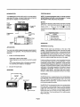
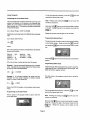
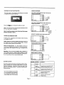
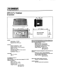
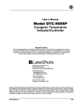
DPCI O-CS Add/Subtract Totalizer (Solid State Inputs)
DPCI O-CC Add/Subtract Totalizer (Contact Inputs)
Ml 663/0693
b- 2.95 ” (74.93mm) -H
f--- 2.677 ” (68mm) -w I
7mm)
POWER
Internal battery:3V, lithium
Life expectancy: 5 years +
Replacement Part:DPClO-BAT
PHYSICAL
Operation Temperature:0”- 55°C
Storage Temperature: -20 to 70°C
Operating Humidity: 90% Non-condensing
#
Weight: 2.2 oz. net
Display Size: .43’high
Front Panel Rating: NEMA-4X when mounted
with gasket provided
Case Material: Cycolac X-17
TOTALIZER
Type: Up/Down Counting
Digits: 8 digits positive/minus sign and 7 digits negative
Scaler: 0.0001- 100.0000
(0.0000 scales by 100 )
Decimal Point: 5 positions, programmable
DC COMMON (Terminal 1)
EXTERNAL RESET INPUT (Terminal 4)
Resets totalizer when connected to dc common.
Minimum Low Time: 0.25 to 1 .O sec. (maintained)
The required pulse width varies with count speed, scale
factor and number of digits displayed.
Voltage Thresholds: Low 0 to 0.4 V dc
High 2.0 to 28 V dc
Recommended
Panel Cutout
I
1.299 ”
(33mm)
COUNT INPUT A (SUBTRACT); COUNT INPUT B (ADD)
(TERMINALS 2&3)
DPCl&CS
Inputs A& B require a voltage source, such as a current sourcing
sensor or a current sinking sensor used with the provided pull up
resistors.
Speed: 0 to 10 kHz
Minimum Low Time: 80 microseconds
Minimum High Time: 20 microseconds
(These times are with a O.OV to 5.0 V swing.)
Input Impedance:2KR above 5 V dc
Voltage Thresholds: Low 0 to 1.2 V dc, High 2.0 to 28 V
dc, Maximum High 28 V dc
DPCl O-CC
Inputs A & B are designed for contact closures to dc common.
Speed: 0 to 20 Hz
Minimum Low Time: 10 milliseconds
Minimum High Time: 40 milliseconds
Input Impedance: 101kD
Voltage Thresholds: Low 0 to 0.4 V dc
High 2.0 to 28 V dc
Maximum High 28 V dc
PROGRAM ENABLE INPUT (Terminal 5)
Operation: Level sensitive (maintained)
COUNT ACCURACY
Absolute when operated within specifications.
INTRODUCTION
PROGRAM MODE
Your OMEGA DPCl 0-CS or DPCIO-CC is a counter with an
eight-digit LCD display. A programmable scaler and decimal
point allow for display in any engineering unit.
NOTE: To enter the program mode, you must connect a
jumper between terminals 1 and 5 (see page 4). To leave
the program mode, disconnect the jumper.
FRONT VIEW
Screens
There are four program-mode screens in the DPCl 0-CS and
DPClO-CC. Upon entering the setup mode, thecounterwill
display screen 1. Press and hold the
141 key while
Plastic
front panel sealed to
meet
NEMA-4X
8-digit LCD
display
repeatedly pressing them key to advance to successive
screens.
I Reset/
Programming
button
Programming
button
REAR VIEW
,
OPERATION
Add/Subtract Counting
APPLICATION
There are two count input terminals on the rear of the
totalizer. Count pulses entering Input A (terminal 3) cause
the total to decrement (count down). Count pulses entering
Input B (terminal 2) cause the total to increment (count up).
The totalizer may start counting from zero, when reset, or
may start from a user-programmed offset value. The offset
value is a positive number and may be up to six digits.
You must make certain programming and wiring choices to
accomplish your application. We recommend the following
sequence:
1.
Answer the following questions:
W hat type ofsensor will be used?
What engineering units should the counter be scaled
to?
?? How many pulses per item is the sensor providing?
?? Is a decimal point needed on the display?
??
If only one of the count inputs is used, the totalizer becomes
an up counter with a range of zero to 99,999,999, or a down
counter with a range of zero to -9,999,999. If both inputs are
used, the totalizer displays the difference count between the
two inputs-counts at Input B are added, counts at Input A are
subtracted. In this mode of operation, the totalizet ’srange is
-9,999,999 to 99,999,999. Positive numbers are not indicated with a plus sign(+). Both inputs may occur simultaneously, in which case the displayed total does not change.
??
2.
Calculate the scale factor.
MOUNTING
Count Inputs
The DPClO-CS has hi-speed inputs and can accept pulses
from solid state, current sourcing sensors at up to 10 kHz per
input. The sensor must supply at least +2.0 V dc, but not
more than +28 V dc to the input. Counts are entered on the
positive-going edge of the pulse.
1
The DPClO-CC has low speed inputs and can accept pulses
from solid state, current sinking sensors or contact closures
to ground at up to 20 Hz per input. These inputs are internally
pulled up to +3 V dc. The sensor must be capable of sinking
current from the input to bring the input voltage down to
+0.4 V dc or less. Counts are entered on the negative-going
edge of the pulse.
‘~‘lnstall mounting clip
Page 2
The far right digit will be flashing. Press the
reaching the desired digit value.
COUNT SCALER
m key until
Calculating the Count Scale Factor
Note: Pressing and holding the m key will cause the
numbers to autoscroll.
The count scale factor is used to convert the incoming count
pulses to the desired unit of measure to be displayed (feet,
gallons, etc.) or to correct for a known amount of error (wheel
wear, viscosity, etc.). This scaler has six digits available with
a fixed decimal point.
Next press them key to move the flashing digit one place
to the left. Change this digit to the desired value with the
m key.
Count Scaler Range: 0.0001 to 99.9999
Repeat this process until all digits are set correctly.
(Setting the count scale factor to 0.0000 will allow scaling by
100)
Programming Decimal Point
Count Scaler (CS) Formula:
cs=E$
The second screen is used to enter the decimal point display
on the totalizer screen. Press and hold the m key and
where:
then press them key to move from screen one to screen
two.
DPF is the decimal point factor corresponding to the desired
decimal point location.
DPF
DISPLAY
xxxxxx = 1
xxxxx.x = 10
xxxx.xx = 100
DISPLAY
DPF
xxx.xxx = 1,000
xx.xxxx = 10,000
Press them key to move the decimal point to the desired
position.
PPI is the number of pulses per item from the sensor.
Programming Offset Value
Example 1: A sensor produces20 pulses per inch of material
travel. Calculate the count scaler required to indicate material used in whole inches(XXXXXX).
cs=
1
20
Programming an offset value allows the counter to reset to a
value other than zero. The offset may be up to six digits. The
offset cannot be a negative number.
= 0.05000
The third screen in the program mode is used to enter the
offset value.
Example 2: An encoder produces 120 pulses
per foot.
Calculate the count scaler required to indicate material
usage in 1/100 ’s of feet (XxXx.Xx).
cs = = = 0.8333
120
(Select the XXXX.XX position on the totalizer decimal point
menu).
The far right digit will be flashing. Press the
reaching the desired digit value.
Programming Count Scale Factor
The first screen in the program mode is used to enter the
count scale factor.
m key until
Note: Pressing and holding the m key will cause the
numbers to autoscroll.
;
Next press them key to move the flashing digit one place
to the left. Change this digit to the desired value with the
m key. Repeat this process until all digits are set
correctly.
Page 3
Enabling the Front Panel Reset Key
WIRING DIAGRAMS
The fourth screen in the program mode allows you to enable
or disable the front panel reset key.
CURRENT SOURCING SENSOR
SOLID STATE ADD/SUBTRACT INPUT (DPClO-CS)
SOLID STATE ADD/SUBTRACT INPUT (DPClO-CS)
CURRENT SINKING SENSOR
+6 to +28 VDC
Press the m key to choose the option you want.
Note: The reset terminal on the rear panel is still active when
the front reset button is disabled.
,
Note: To exit the program mode, disconnect the jumper
between terminals 1 and 5.
Sensor
CONTACT CLOSURE COUNT INPUT (DPClO-CC)
WIRING RECOMMENDATIONS
Following these suggestions will increase noise immunity
and lengthen unit life.
Cable: Make the connection between the count source and
the totalizer with a two-conductor shielded cable. Connect
the shield to earth ground at one end only.
PROGRAM MODE ENABLE (All Models)
Relay Coil Suppression: If a relay contact is used as a
count source, suppress the relay coil. This can be accomplished with an RC network for AC coils or a diode for DC
coils.
Mounting: Do not mount the totalizer near a solenoid or
other inductive devices. Supply enough ventilation to keep
the totalizer operating within the temperature specifications.
Do not mount this unit in a heavy vibration area.
REMOTE RESET (All Models)
[_Zk
BATTERYSAFETY
Terminal
Function
The lithium battery that powers your device contains inflammable materials such as lithium organic solvent, and other
chemical ingredients. Explosion or fire may result if the
battery is not handled correctly. To avoid an accident follow
these guidelines:
1
Ground
2
Input B
Count input
Current Source Input (DPClO-CS)
Current Sink Input (DPClO-CC)
3
Input A
Count Input
Current Source Input (DPCIO-CS)
Current Sink Input (DPCIO-CC)
4
Reset
Connect through Contact
Closure to Ground
5
Program
Enable
Connect to Ground to Enter
Program Mode
Do not heat batteries above 95°C
Do not recharge lithium batteries
?? Do not dispose of batteries in fire
?? Insert battery with correct polarity
??
??
Page 4
Operation
_
^.._
OTHER OMEGA M
REPLACEMENT PARTS
DPC Ol - BAT
46066-210
53300-241
28772-200
,
DPC
DPC
DPC
DPC
Ba tt e ry
Gaske t
M oun ti ng C li p
M oun ti ng Sc r ew
0l - K
0I - QT
I O - RM
0l - RT
I N I COUNTER PRODUCTS
To t a li ze r
Quad r a t u r e I nd i ca t o r
Ra t e m e t e r
R a t e m e t e rfl o t a li zer
OMEGA wa
rrants this unit to be free of defects
in materials and workmanship and to give
satisfactory service for a period of 13 months from date of purchase. OMEGA Warranty
adds an additional one (1) month grace period to the normal
one (1) year product
warranty to cover handling and shipping time. This ensures that our customers receive
maximum coverage on each product. If the unit should malfunction, it must be returned
to the factory for evaluation. Our Customer Service Department will issue an Authorized
Return (AR) number immediately upon phone or written request. Upon examination by
OMEGA, if the unit is found to be defective it will be repaired or replaced at no charge.
However, this WARRANTY is VOID if the unit shows evidence of having been tampered
with or shows evidence of being damaged as a result of excessive corrosion; or current,
heat, moisture or vibration; improper specification; misapplication; misuse or other
operating conditions outside of OMEGA
’s control. Components which wear or which are
damaged by misuse are not warranted. These include contact points, fuses, and triacs.
We are glad to offer suggestions on the use of our various products.
Neve rt
less OMEGA on l warrants
y
that the parts manufactured by it will be as specified
and free of defects.
he -
OMEGA MAKES NO OTHER WARRANTIES OR REPRESENTATIONS OF ANY KIND
WHATSOEVER, EXPRESSED OR IMPLIED, EXCEPT THAT OF TITLE AND ALL
IMPLIED WARRANTIES INCLUDING ANY WARRANTY OF MERCHANTABILITY
AND FITNESS FOR A PARTICULAR PURPOSE ARE HEREBY DISCLAIMED.
LIMITATION OF LIABILIm The remedies of buyer set forth herein ara exclusive
and the total liability of OMEGA with respect to this order, whether based on
contract, warranty, negligence, indemnification, strict liability or otherwise,
shall not exceed the purchase price of the component upon which liability is
based. In no event shall OMEGA be lieble for consequential, incidental or special
damages.
Every precaution for accuracy has been taken in the preparation
ofthis manual, however,
OMEGA ENGINEERING, INC. neither assumes responsibility for any omissions or errors
that may appear nor assumes liability for any damages that result from the use of t he
products in accordance with the information contained in the manual.
,
-.
: ‘I~
RETURN
.~ ,, < @ _A
il.6
’
, ‘il,
REQUESTS / lNQUlRlES &$~~
‘~
,\sp
‘y+w
”: ‘rr;
Direct all warranty and repair requests/inquiries to the OMEGA ENGINEERING Customer
Service Department. Call toll free in the USA and Canada: l-800-622-2378, FAX: 203-359761 1; lnternational:203-359-1660, FAX: 203-359-7807.
BEFORE RETURNING ANY PRODUCT(S) TO OMEGA, YOU MUST OBTAIN AN AUTHO
UFD RFTURN (AR) NUMm FROM OUR CUSTOMER SERVICE DEPARTMENT
(IN
ORDER TO AVOID PROCESSING DELAYS). The assigned AR number should then be
marked on the outside of the return package and on any correspondence Please have. t he
following information available BEFORE contacting OMEGA:
1. P.O. number under which the product was PURCHASED,
2. Model and serial number of the product. and
3. Repair instructions and/or specific problems you are having with the
product.
OMEGA ’s policy is to make running changes, not model changes, whenever an improvement is
possible. That way our customers ger the latest in technology and engineering.
OMEGA is a registered trademark of OMEGA ENGINEERING, INC.
Q Copyright 1993 OMEGA ENGINEERING, INC. All rights reserved including illustrations.
Nothinginthismenualmaybereproducedinanymanner,eitherwhollyorinpa~forenypurpose
Printed in U.S.A.
whatsoever without written permission from OMEGA ENGINEERING, INC.
Page 5
;; &
OMEGA@ . . . Your Sdurce for
Process Measurement and Control
TEMPERATURE
Thermocouple, RTD & Thermistor Probes, Connectors, Panels & Assemblies
Wire: Thermocouple, RTD & Thermistor
Calibrators 8 Ice Point References
Recorders, Controllers 8 Process Monitors
Infrared Pyrometers
PRESSURE/STRAIN FORCE
m Transducers & Strain Gauges
B Load Cells 8 Pressure Gauges
5 Displacement Transducers
m Instrumentation 8 Accessories
FLOW/LEVEL
B Rotameters, Gas Mass Flowmeters 8 Flow Computers
[g Air Velocity Indicators
fij’TurbinelPaddlewheel Systems
fij’ Totalizers & Batch Controllers
pH/CONDUCTIVITY
w
pH Electrodes, Testers & Accessories
m BenchtopRaboratory Meter s
m Controllers, Calibrators, Simulators & Pumps
m
Industrial pH & Conductivity Equipment
DATA ACQUISITION
m
[g
m
Data Acquisition and Engineering Software
Communications-Based Acquisition Systems
Plug-in Cards for Apple, IBM & Compatibles
@ Datalogging Systems
@ Recorders, Printers & Plotters
HEATERS
w Heating Cable
w Cartridge & Ship Heaters
fij’ Immersion & Band Heaters
m Flexible Heaters
@ Laboratory Heaters
ENGINEERING INC.
One Omega Drive, P.O. Box 4047
Stamford, CT 06907
Tel: (203) 359-1660
Telex: 996404 Cable OMEGA
Fax: (203) 359-7700