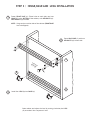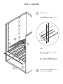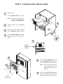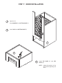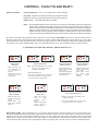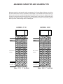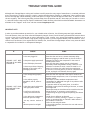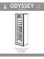
1
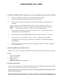
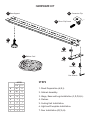
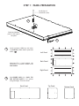
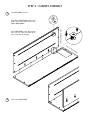
ODYSSEY WINE CELLAR ASSEMBLY & OPERATION MANUAL 110 220 READ BEFORE YOU START 1. LOCATING YOUR WINE CELLAR - Remember, it is not only an appliance but also a piece of furniture A. Provide 3” minimum clearance for all surfaces especially top and back. Under no circumstances should the unit be “built-in” in any way. B. Never locate your wine cellar outdoors or in an area with extremes of temperature and humidity. Garages, attics, unnished basements, laundry rooms, breezeways, closets or any unventilated room. In other words these units must be installed in air-conditioned environments which do not “trap” the warm air being exhausted C. Temperatures in surrounding area must not exceed 80 °F (25 °C) with humidity levels not to exceed 80% R.H. (Relative Humidity). D. Outlet power must be a DEDICATED separately fused, grounded, 15 Amp 110 - 120 V line E. You must monitor your unit DAILY. If unit is in “Alarm”, unplug the unit inmediately. Vintage Keeper will not be liable or responsible for incidental or consequential damages. (See Warranty). F. Place unit in a clean area and allow access to the exterior surfaces for periodic vacuuming of the condensor coil 2. AREA FOR ASSEMBLING YOUR WINE CELLAR Choose a clear 12’ by 12’ area with a level oor and carpenting to help reduce scratching of surfaces. 3. TOOLS * * * * * Hex wrench (included) Phillips screwdriver Rubber mallet Carpenter’s level Helper or two is strongly recommended 4. TEST THE COOLING UNIT Plug it in for a few minutes on a table top, to verify that controls and display are functional, and that the unit is producing cool air after a few minutes of operation. Note that the electronic controller has a one-minute cautionary delay between initial plug-in and start-up of the compressor. Record the serial number (located on both front and rear surfaces of the cooling unit) and ll out and fax or mail the warranty registration sheet. or register your warranty on-line at www.vintagekeeper.com. HARDWARE KIT C A Base Support B Connector Clip Silver Clip Screw D Leg E Washer I Rubber Cord F Hinge G Hex Bolt H Hex Wrench MODEL 110 220 A B C D E F G 20 20 2 4 1 2 14 24 24 2 4 1 2 14 H I 1 1 1 1 STEPS 1. Panel Preparation (A,B,I). 2. Cabinet Assembly. 3. Hinge, Base and Legs Installation (C,D,F,G,H). 4. Shelves. 5. Cooling Unit Installation. 6. Light and Faceplate Installation. 7. Door Installation (E,F,G,H). STEP 1 : PANEL PREPARATION Use Philips # 2 screwdriver (star) 1 Round end ALWAYS points to the edge of the panel 2 1 Install connector CLIPS (A) with silver clip SCREW(B) in Back Panel’s predrilled holes. ( ) Open box V5 or V2 and continue the installation of connector CLIPS in the SIDE PANELS. Left Panel Back Panel Right Panel 2 Push RUBBER CORD (I) in BACK, TOP AND BOTTOM PANELS in all grooves along side edges. Trim with cutter. Back Panel Top Panel Bottom Panel STEP 2 : CABINET ASSEMBLY 1 Lay BACK PANEL on oor Align TOP of SIDE PANEL(open end of hooks must point towards top) with TOP of BACK PANEL TOP OF RIGHT PANEL Push SIDE PANEL rmly downwards until you fully insert all CLIPS (A) in the corresponding housings. TO P 2 Insert other SIDE PANEL OF BA CK PA N EL STEP 2 : CABINET ASSEMBLY CONTINUED 3 TO P Insert the BOTTOM and TOP PANEL SLIGHTLY strech the side panels, start inserting the BOTTOM (rear) side rst and work upwards, then push or hammer with a rubber mallet around sides. PA N DO NOT HIT THE CENTER OF PANELS! TOP PANEL can be identied by two hangers BO TT OM PA N EL 4 RUBBER ONLY Be sure that all PANELS are fully inserted and all CLIPS (A) are touching the corresponding panel before you continue . . . Lock the PANELS with half turn of a phillips (star) screwdriver to the CLIPS (A) Half turn, DO NOT FORCE EL STEP 3 : HINGE,BASE AND LEGS INSTALLATION 1 Fasten FRONT BASE (C) (Three holes at each side) and one HINGE (F) to the BOTTOM of the cabinet, with HEX BOLTS (G). HEX WRENCH (H) included NOTE : Hinge can be on either side of the cabinet (FRONT BASE has to be ipped) 2 FR ON TB Fasten BACK BASE (C) with two HEX BOLTS (G) at each side AS E 1 CA BO B I N TT E T OM 3 BA CK 3 BA SE 2 Install four LEGS (D) into BASES (C) Raise cabinet and adjust the level by turning (clockwise) the LEGS (D) as needed. Use a carpenter’s level STEP 4 : SHELVES 1 Open box V4 or V5 Hook SHELVES into hangers starting from the bottom of cabinet PRESS TOP 1 BOTTOM 1 2 HINT : 1 Snap SHELVES into hangers on one side 2 Push the SHELVES down to snap into opposite side hangers 1 2 3 4 5 6 7 CA BO B I N TT E T OM 2 2 Place the numbered COVERS on the front end of the SHELVES STEP 5 : COOLING UNIT INSTALLATION 1 Open box AA Lift the COOLING UNIT to top shelf NOTE : Place it on a spacer (phonebook) to get it level with the cut-off of the BACK panel 2 COOLING UNIT Take out power cord trough BACK panel 1 out PH 2 57 D robo t contr ols ADJU ST 1 2 ON 2 EB OO 3 4 1 K 5 3 Slide unit over the rubber isolators until MOUNTING TABS interlock 4 Hook the SENSOR WIRE in the available rear hanger on the side of the cabinet 6 7 3 4 DIGITAL TEMPERATURE SENSOR 1 out 2 57 ADJUST Drobot controls 5 6 5 CO VE RP LA TE NOTE : Do not over tighten screws, cover should seal but the metal should not touch the cabinet BA CK AIR DEFLECTOR Screw on back COVERPLATE to rear side of COOLING UNIT at each corner (screws supplied with cooling unit) 6 Snap in the AIR DEFLECTOR, place onto bottom tabs, push, then ex side and let it sping back into side tab STEP 6 : LIGHT AND FACEPLATE INSTALLATION 1 1 Plug in the light cord into the side of COOLING UNIT 2 Hook FACEPLATE on 4 plastics tabs preinstalled in the side 1. push 2. slide down 2 2 1 out 2 57 D robo t cont rols ADJ 1 UST 1 2 3 FA CE Fasten LIGHT CLIPS into mounting holes predrilled on front edge of TOP panel 3 PL AT E 4 5 6 7 3 4 1 out 2 57 D robo 1 ou t cont rols ADJ UST t2 57 D robo t cont rols ADJ UST 5 1 ou 4 Snap LIGHT in LIGHT CLIPS plug small end of power cord into socket on side of light 5 Snap LIGHTCOVER into LIGHT t2 57 D robo t cont rols ADJ UST STEP 7 : DOOR INSTALLATION 1 Open box V3 Place WASHER (E) on BOTTOM HINGE (F) 2 Insert DOOR onto BOTTOM HINGE (F) 2 1 3 1 ou 3 t2 57 Dr ob ot cont ro ls AD JU ST Install TOP HINGE (F) with HEX BOLTS (G) NOTE : Adjust nal position of the door before tightening the bolts CONTROLS, PLUG IT IN AND ENJOY ! DEFAULT SETTINGS : Storage Temperature : 57°F / 14°C (ideal temp for wine cellaring) Fan Speed: Optimized for maximum efciency and moderate noise Display: Set-Temp in Fahrenheit degrees (during normal operation) Digital Sensor: Reads AIR temperature in cabinet NOTE: By reading AIR temperature in the cabinet, the controller will respond more quickly to temperature change than if reading actual LIQUID temperature, because liquid temperature changes about 10 times more slowly than air. Although air temperature in the cabinet may change 7 or 8 degrees during a complete On/Off cycle, the liquid temperature, which corresponds to your selected SETTEMP, will remain constant, typically within one degree F. The Digital Sensor, which is encased in a red vinyl cap and permanently mounted on the side of the unit, must not be handled or modied. One-minute cautionary delay between plug-in and start-up, also between EACH RESET and start-up. Unit will auto-switch to Emergency fan speed on initial power-up and whenever it reads a cabinet temperature three degrees above Set, and will then adjust to Default or selected fan speed when it reaches one degree above Set. Unit will display Set-Temp when reading temp within two degrees of Set; when reading a higher temp, for example during initial cycle, unit will display actual air temp in cabinet. IF YOU MUST PLAY WITH THE CONTROLS, HERE IS HOW TO DO IT . . . 1 OUT 2 Drobot Controls ADJUST TM Display cabinet temperature PRESS and HOLD “UP” arrow to display actual air temperature in cabinet; RELEASE “UP” arrow to return display to Set Temperature SET ADJUST TM Drobot Controls 1 SET Drobot Controls SET ADJUST TM Drobot Controls ADJUST TM 2 Change set temperature NOTE: When making ANY changes to controller settings, it’s best to do so when the compressor is cycled OFF 1. PRESS and RELEASE “SET” 2. Press “UP” or “DOWN” arrow, once per degree New Set-Temp is retained in memory, after reset and 1-minute cautionary delay SET Drobot Controls Change Fan Speed from DEFAULT to QUIET2: Change Fan Speed from QUIET2 to QUIET1: PRESS and HOLD “SET” 4 seconds, until indicator “Out 2” lights: QUIET2 mode = Moderate fan speed, less efciency, quieter operation PRESS and HOLD “SET” 4 seconds, until indicator “Out 1” lights: QUIET1 mode = Slowest fan speed, least efciency, quietest operation 1 OUT 2 1 OUT 2 ADJUST TM 1 OUT 2 SET ADJUST TM 1 OUT 2 1 OUT 2 Drobot Controls SET Drobot Controls 1 OUT 2 1 OUT 2 1 OUT 2 SET ADJUST TM Change Fan Speed from QUIET1 to DEFAULT: Change Temperature Display (F/C): PRESS and HOLD “SET” 4 seconds, until both lights are off: DEFAULT mode = auto speed control, maximum efciency PRESS “SET” and “UP” arrow to toggle between F° and C° display NOTE: Changing Temp Display resets ALL settings to DEFAULT SET Drobot Controls TM SET ADJUST Drobot Controls 1 ADJUST TM 2 To Re-calibrate Digital Sensor: 1. PRESS and HOLD “UP” and “DOWN” arrows, to display “0” offset 2. Press “UP” or “DOWN” arrow, once per degree, to change offset from +4 to -4 degrees RESET FROM ALARM : Alarm will Display (“AL”) if controller reads temp above 72F and is unable to lower the temp after autoswitching to Emergency speed. If the condition persists even after auto-reset, the unit will shut itself off. To correct the condition: unplug the cooling unit, inspect cabinet assembly and seal any cracks, adjust the door to seal more tightly, take steps to reduce ambient temp, remove any obstruction and/or dust buildup on the exhaust side, compensate for heat gain if any cabinet walls receive direct sunlight. Plug the unit in and toggle the display, by pressing “SET” and “UP” arrow, to restore all Default settings. MAXIMUM CAPACITIES AND LOADING TIPS Maximum capacities and sample loading arrangements for Vintage Keeper Odyssey wine cellars are illustrated below. Note the variations in shelf height, to accomodate the widest variety of bottle types and sizes. Standard Burgundy and Bordeaux bottles are best arranged with necks facing out; some taller bottles may need to be arranged neck to neck. Never stack bottles more than two rows high on a shelf; all shelves must be installed as directed. Avoid placing bottles directly in front of the cooling unit’s circulating fan. MODEL 110 MODEL 220 26 13 Max 4" dia. bottles 7 Max 3.5" dia. bottles 3 rows 3" dia. or 2 rows 4.5" dia. Max 4" dia. bottles 14 7 14 7 14 7 14 7 14 7 7 Max 3.5" dia. bottles 14 14 7 14 7 14 7 14 7 14 20 Max: 110 3" bottles 3 rows 3" dia. or 2 rows 4.5" dia. 40 Max: 220 3" bottles TROUBLE SHOOTING GUIDE Although each Vintage Keeper cooling unit has been carefully tested at every stage of manufacture, occasional problems arise, the majority of which are due to rough or careless handling during shipping or installation. Other problems may derive from improper cabinet assembly, power interruption or surge, low line voltage (less than 105V), or failure to clean the unit regularly. The following may help you determine what the problem may be, what steps you can take to correct it, and what further steps may be required. Additional Trouble-Shooting information and downloadable documents are available in the “Support” area of our web site: www.vintagekeeper.com IMPORTANT NOTE: In order to provide maximum protection for your valuable wine collection, the following steps are highly advisable. First and foremost, have your wine collection adequately insured. Second, install a battery-powered heat-sensitive alarm to warn of any loss of cooling due to power interruption. Third, monitor your storage and ambient conditions on a regular, daily basis. Fourth, install a high quality surge supressor to protect against sudden power uctuations. Fifth, clean the unit as directed, on a regular basis. Be advised, also, that Drobot-Vintage Keeper cannot in any event be liable or responsible for incidental or consequential damages. IF: CHECK: - Is the unit plugged in? COOLING UNIT DOES NOT RUN AT ALL WHEN PLUGGED IN - Is the power supply operational? - Is the LED display functional? - Is there any evidence of shipping damage on the cooling unit or packaging materials? - Is the storage temp properly set? - Is the cabinet properly assembled, with all joints air tight? COOLING UNIT RUNS BUT DOES NOT COOL SUFFICIENTLY - Is the door properly adjusted to seal tightly when closed? - Is airow to and from the cooling unit unobstructed? - Is the ambient air temperature within the specied range? - Are any exterior surfaces of the cabinet exposed to sunlight? THEN: - Note that the unit has a 1-minute cautionary delay between plugging in and full start-up; this is a built-in safeguard to protect the compressor in the event of sudden power failure - Note that the power supply must be a dedicated, separately-fused and grounded 15 Amp, 120V line. If an extension cord must be used, it must be rated for 15 Amps. Do not share the outlet with other appliances - If the unit is receiving power yet fans or compressor fail to run, unplug for ten minutes, then try again - Note that the unit may take a few days to achieve the desired storage temperature, even in a properly located, airtight cabinet - Take steps to reduce ambient temperatures and compensate for additional heat gain if any cabinet walls receive direct sunlight - If gaps are visible at any panel joints, it would be advisable to apply silicone caulking to the area, to ensure an airtight seal - Take steps to improve circulation of air to and from the unit - Adjust the door, if necessary, to seal tightly by re-positioning the upper hinge and improving the cabinet level - Install the air deector as directed - If the unit is currently running in “Quiet2” or “Quiet1” mode, try switching back to “Default” mode and see if the problem is corrected - Clean the fan and grille areas - If the problem persists, disconnect the unit and contact Vintage Keeper LIMITED WARRANTY AND PRODUCT SUPPORT ONE YEAR LIMITED WARRANTY If your Vintage Keeper cooling unit or cabinet fails to perform as designed within one year of the date of purchase, VINTAGE KEEPER INC. warrants that, upon your request, it will be repaired or replaced, at our option, during the one-year warranty period. This warranty applies only to the rst end-user purchaser of a Vintage Keeper unit that is purchased and used in the continental United States or Canada. It is not valid for subsequent purchasers, nor for units in use outside North America. The warranty period for your Vintage Keeper unit commences on the date you purchased it and expires one year thereafter. PROOF OF PURCHASE Within 10 days of purchase, complete and mail, fax or e-mail the enclosed registration sheet to VINTAGE KEEPER INC. Alternately, you may register your warranty on our Internet web site, www.vintagekeeper.com. When you make a warranty claim, you must forward a copy of your original dated bill of sale to establish your date of purchase. IF YOU HAVE A PROBLEM WITH YOUR UNIT Customer service and warranty problems are handled online at www.vintagekeeper.com. You will nd a comprehensive welldocumented and easy-to-use solution to almost any question or problem you may have. The inquiry forms are lled in on-line and connect you to our representatives who will process your requests for warranty service. This is the quickest way to solve your problems. If you do not have access to the internet you may call us from 9:00 a.m to 4:00 p.m EST, to request a WARRANTY CLAIM INFORMATION KIT. We can fax or mail it to you. You can ll in the enclosed REQUEST FOR RETURN AUTHORIZATION CODE form and return it by mail or fax. We can then promptly process your claim. REPLACEMENT ? At our option we may choose to offer you a replacement part or product rather than a repair. Upon your authorization to accept a replacement unit and with appropriate security (credit card authorization), we will promptly ship a replacement unit. The replacement may be a unit that has been reconditioned by VINTAGE KEEPER INC. The unit that needs service must be packed and returned to us, shipping prepaid. Upon its receipt, we will release your credit card security. Go online to the SUPPORT section on our web site at www.vintagekeeper.com to request warranty service. REPAIR ? If we determine that your unit needs to be repaired rather than replaced, go online to the SUPPORT section on our web site at www.vintagekeeper.com to request warranty repair service. I/we determinate that your part or product needs to be repaired rather than replaced we will issue you a return authorization code. Please save the original packaging materials to facilitate shipment. Mark the Return Authorization code clearly on the outside of the package, enclose a brief note describing the problem and send the unit, shipping prepaid, to VINTAGE KEEPER INC. WHAT MUST YOU DO? Your unit is designed to perform with a minimum amount of user maintenance when installed and operated precisely as directed in the enclosed manual. You are, however, responsible for the required user maintenance described in the manual, specically, regular cleaning of the condensor coil and fans. Also, you must take steps to protect the unit from sudden power surge. As with any sensitive electronic device, your Vintage Keeper unit may be damaged by power surges or spikes, sudden interruptions or prolonged low-voltage conditions, which are not covered by this Warranty. You must monitor your unit’s performance on a daily basis. If there is an apparent problem or “Alarm” condition, you must disconnect the power supply to avoid potential damage to your wine collection. It is your responsibility to insure your wine, and to take all reasonable and necessary precautions to safeguard its condition. WHAT THE WARRANTY DOES NOT COVER This warranty covers only defects in materials and workmanship provided by VINTAGE KEEPER INC. and does not cover equipment damage or malfunction from misuse, abuse, accident, act of God, or any unauthorized alteration or modication. The product must have been installed and operated precisely as directed in the manual which acompanies each product. Improper return shipping, inadequate packaging or shipping damage is not covered unless the unit is packaged and shipped in accordance with Vintage Keeper replacement procedures. This product is not warranted for COMMERCIAL USE. Such usage will void any warranty. Third party servicing of this product during the warranty period will also void the warranty. REPLACEMENT AND REPAIR ARE YOUR ONLY REMEDIES YOUR ONLY REMEDY UNDER THIS WARRANTY IS THE REPLACEMENT OR REPAIR OF YOUR ELIGIBLE PRODUCT AS DESCRIBED ABOVE. NEITHER THIS WARRANTY NOR ANY OTHER WARRANTY, EXPRESS OR IMPLIED, INCLUDING, BUT NOT LIMITED TO, THE IMPLIED WARRANTIES OF MERCHANTABILITY AND FITNESS FOR A PARTICULAR PURPOSE, SHALL EXTEND BEYOND THE ONE-YEAR WARRANTY PERIOD. UNDER NO CIRCUMSTANCES SHALL VINTAGE KEEPER INC. BE LIABLE FOR ANY SPECIAL INCIDENTAL, INDIRECT OR PUNITIVE DAMAGES OR FOR ANY CONSEQUENTIAL DAMAGES, INCLUDING SPOILAGE OF WINE, EVEN IF VINTAGE KEEPER INC. KNOWS OR IS INFORMED THAT SUCH DAMAGES ARE POSSIBLE. IT IS YOUR RESPONSIBILITY TO INSURE YOUR WINE, AND TAKE ALL REASONABLE, NECESSARY PRECAUTIONS TO SAFEGUARD ITS CONDITION. SOME STATES DO NOT ALLOW THE EXCLUSION OR LIMITATION OF INCIDENTAL OR CONSEQUENTIAL DAMAGES, SO THE ABOVE EXCLUSION OR LIMITATION MAY NOT APPLY TO YOU. NO RESELLER IS AUTHORIZED TO MODIFY THE TERMS OF THIS WARRANTY. ANY ADDITIONAL WARRANTY OFFERED BY A RESELLER IS THE SOLE RESPONSIBILITY OF THAT RESELLER. SERVICE AFTER YOUR WARRANTY EXPIRES If your unit requires service after the one-year warranty period expires, you may have it serviced locally by any qualied HVAC technician, or you may purchase a new unit at a special discount under our Extended Warranty Program, Please be ready to provide model, serial number, credit card number and a copy of your original dated bill of sale. In addition, repair service is always available direct from us at at rates below the prevailing charges for local service. However, using our Extended Warranty Program for units under 5 years old will always be a preferable solution to returning a unit for repair. Go online at www.vintagekeeper.com to request access to our Extended Warranty Program. ODYSSEY WINE CELLAR 5648 McAdam Rd., Mississauga ON CAN L4Z 1T2 Phone : 905.501.8582 Fax : 905.501.0889 Toll free: 1.888.274.8813 [email protected] www.vintagekeeper.com 110 220