1
NN10364-301
Multimedia Communication Portfolio
Multimedia Communication Server
2-server Sun Fire V100 Solaris Installation and Commissioning
Guide
MCS 5100 3.5
Standard
6.0
December 2006
Copyright © 2006 Nortel Networks
3
Contents
Finding the latest updates on the Nortel Web site . . . . . . . . . . . . . . . . . . . .7
How to get help . . . . . . . . . . . . . . . . . . . . . . . . . . . . . . . . . . . . . . . . . . . . . . . .9
Overview . . . . . . . . . . . . . . . . . . . . . . . . . . . . . . . . . . . . . . . . . . . . . . . . . . . . 11
Restrictions and limitations . . . . . . . . . . . . . . . . . . . . . . . . . . . . . . . . . . . . . . 13
MCS 5100 documentation . . . . . . . . . . . . . . . . . . . . . . . . . . . . . . . . . . . . . . . 14
Before you start the installation . . . . . . . . . . . . . . . . . . . . . . . . . . . . . . . . . 17
Prerequisites . . . . . . . . . . . . . . . . . . . . . . . . . . . . . . . . . . . . . . . . . . . . . . . . . 17
Acronyms . . . . . . . . . . . . . . . . . . . . . . . . . . . . . . . . . . . . . . . . . . . . . . . . . . . 18
Key stroke symbols . . . . . . . . . . . . . . . . . . . . . . . . . . . . . . . . . . . . . . . . . . . . 19
Text conventions used in this document . . . . . . . . . . . . . . . . . . . . . . . . . . . . 19
Server configuration . . . . . . . . . . . . . . . . . . . . . . . . . . . . . . . . . . . . . . . . . . .20
Loading disks . . . . . . . . . . . . . . . . . . . . . . . . . . . . . . . . . . . . . . . . . . . . . . . . 20
Minimum and recommended requirements for customer-provided PC . 23
Setting up the baseline hardware . . . . . . . . . . . . . . . . . . . . . . . . . . . . . . . . 25
Baseline hardware . . . . . . . . . . . . . . . . . . . . . . . . . . . . . . . . . . . . . . . . . . . . 25
Setting up rack to mount hardware . . . . . . . . . . . . . . . . . . . . . . . . . . . . . . . . 27
Connecting the Sun Fire V100 server to the layer-2 switch . . . . . . . . . . . . . 28
Connecting the Sun Fire V100 server to the MRV LX terminal server . . . . . 29
Installing and accessing the MRV LX-4000 series terminal server . . . . . 33
Powering on the servers . . . . . . . . . . . . . . . . . . . . . . . . . . . . . . . . . . . . . . . 45
Installing Disks 1 to 3 . . . . . . . . . . . . . . . . . . . . . . . . . . . . . . . . . . . . . . . . . . 47
Installing CD1 . . . . . . . . . . . . . . . . . . . . . . . . . . . . . . . . . . . . . . . . . . . . . . . . 47
Installing CD2 . . . . . . . . . . . . . . . . . . . . . . . . . . . . . . . . . . . . . . . . . . . . . . . . 52
Installing CD3 . . . . . . . . . . . . . . . . . . . . . . . . . . . . . . . . . . . . . . . . . . . . . . . . 53
Installing Disk 4 . . . . . . . . . . . . . . . . . . . . . . . . . . . . . . . . . . . . . . . . . . . . . . .55
Database/Accounting/Management server (DBSvr, AcctMgr, MgmtSvr) . . . 55
Application servers (SIP Application Module, IPCM, Web Client Manager,
Provisioning Module) . . . . . . . . . . . . . . . . . . . . . . . . . . . . . . . . . . . . . . . 59
Installing Disk 5 (all servers) . . . . . . . . . . . . . . . . . . . . . . . . . . . . . . . . . . . .63
Enabling or disabling the automatic mount . . . . . . . . . . . . . . . . . . . . . . . . 65
MCS 2-server Sun Fire V100 Solaris Installation and Commissioning Guide
Copyright © 2006 Nortel Networks
4
Installing Disk 6 (MgmtSvr/AcctMgr only) . . . . . . . . . . . . . . . . . . . . . . . . . 67
Installing Oracle 9.2.0.4 on the database server . . . . . . . . . . . . . . . . . . . . 69
Installing Oracle 9.2.0.4 . . . . . . . . . . . . . . . . . . . . . . . . . . . . . . . . . . . . . . . . 69
Deploying the initial database load . . . . . . . . . . . . . . . . . . . . . . . . . . . . . . . 73
Prerequisites . . . . . . . . . . . . . . . . . . . . . . . . . . . . . . . . . . . . . . . . . . . . . . . . . 73
Deploying the MCS database load (imssipdb) . . . . . . . . . . . . . . . . . . . . . . . 73
Deploying and starting the Sysmgr . . . . . . . . . . . . . . . . . . . . . . . . . . . . . . . 75
Prerequisites . . . . . . . . . . . . . . . . . . . . . . . . . . . . . . . . . . . . . . . . . . . . . . . . . 75
Deploying and starting the Sysmgr . . . . . . . . . . . . . . . . . . . . . . . . . . . . . . . . 75
Sysmgr deployment verification . . . . . . . . . . . . . . . . . . . . . . . . . . . . . . . . . . 77
Registering your license key . . . . . . . . . . . . . . . . . . . . . . . . . . . . . . . . . . . . 79
Installing and launching the System Management Console . . . . . . . . . . . 95
Prerequisites . . . . . . . . . . . . . . . . . . . . . . . . . . . . . . . . . . . . . . . . . . . . . . . . . 95
Installing the System Management Console . . . . . . . . . . . . . . . . . . . . . . . . . 95
Launching the System Management Console . . . . . . . . . . . . . . . . . . . . . . . 96
Adding a server . . . . . . . . . . . . . . . . . . . . . . . . . . . . . . . . . . . . . . . . . . . . . .101
Prerequisites . . . . . . . . . . . . . . . . . . . . . . . . . . . . . . . . . . . . . . . . . . . . . . . . 101
Adding a server . . . . . . . . . . . . . . . . . . . . . . . . . . . . . . . . . . . . . . . . . . . . . .101
Adding and configuring the Accounting Module . . . . . . . . . . . . . . . . . . . 103
Prerequisites . . . . . . . . . . . . . . . . . . . . . . . . . . . . . . . . . . . . . . . . . . . . . . . . 103
Procedures . . . . . . . . . . . . . . . . . . . . . . . . . . . . . . . . . . . . . . . . . . . . . . . . .103
Adding and configuring the SIP Application Module . . . . . . . . . . . . . . . 107
Prerequisites . . . . . . . . . . . . . . . . . . . . . . . . . . . . . . . . . . . . . . . . . . . . . . . . 107
Procedures . . . . . . . . . . . . . . . . . . . . . . . . . . . . . . . . . . . . . . . . . . . . . . . . .107
Adding and configuring the IP Client Manager . . . . . . . . . . . . . . . . . . . . 119
Prerequisites . . . . . . . . . . . . . . . . . . . . . . . . . . . . . . . . . . . . . . . . . . . . . . . . 119
Procedures . . . . . . . . . . . . . . . . . . . . . . . . . . . . . . . . . . . . . . . . . . . . . . . . .119
Installing the UFTP BaseSoftware . . . . . . . . . . . . . . . . . . . . . . . . . . . . . . . 125
Prerequisites . . . . . . . . . . . . . . . . . . . . . . . . . . . . . . . . . . . . . . . . . . . . . . . . 125
Add the UFTP to the System Management Console . . . . . . . . . . . . . . . . . 125
Configuring the Provisioning Module . . . . . . . . . . . . . . . . . . . . . . . . . . . . 127
Prerequisites . . . . . . . . . . . . . . . . . . . . . . . . . . . . . . . . . . . . . . . . . . . . . . . . 127
NN10364-301 MCS 5100 3.5 Standard 6.0 December 2006
Copyright © 2006 Nortel Networks
Procedures
5
. . . . . . . . . . . . . . . . . . . . . . . . . . . . . . . . . . . . . . . . . . . . . . . . .127
Adding and configuring the Web Client Manager . . . . . . . . . . . . . . . . . . 133
Prerequisites . . . . . . . . . . . . . . . . . . . . . . . . . . . . . . . . . . . . . . . . . . . . . . . . 133
Procedures . . . . . . . . . . . . . . . . . . . . . . . . . . . . . . . . . . . . . . . . . . . . . . . . .133
Installing and configuring the Oracle Monitor . . . . . . . . . . . . . . . . . . . . . 139
Prerequisites . . . . . . . . . . . . . . . . . . . . . . . . . . . . . . . . . . . . . . . . . . . . . . . . 139
Procedures . . . . . . . . . . . . . . . . . . . . . . . . . . . . . . . . . . . . . . . . . . . . . . . . .139
Installing the iPlanet Monitor . . . . . . . . . . . . . . . . . . . . . . . . . . . . . . . . . . . 147
Prerequisites . . . . . . . . . . . . . . . . . . . . . . . . . . . . . . . . . . . . . . . . . . . . . . . . 147
Procedures . . . . . . . . . . . . . . . . . . . . . . . . . . . . . . . . . . . . . . . . . . . . . . . . .147
Verification procedures . . . . . . . . . . . . . . . . . . . . . . . . . . . . . . . . . . . . . . . 161
Verifying Server1 (DBSvr/MgmtSvr/AcctMgr) . . . . . . . . . . . . . . . . . . . . . . . 161
Verifying Server2 (application server) . . . . . . . . . . . . . . . . . . . . . . . . . . . . . 163
Verifying the database load (imssipdb) deployment . . . . . . . . . . . . . . . . . .165
Deploying the PC Client . . . . . . . . . . . . . . . . . . . . . . . . . . . . . . . . . . . . . . .167
Reloading IP addresses after system installation . . . . . . . . . . . . . . . . . .169
MCS 2-server Sun Fire V100 Solaris Installation and Commissioning Guide
Copyright © 2006 Nortel Networks
6
NN10364-301 MCS 5100 3.5 Standard 6.0 December 2006
Copyright © 2006 Nortel Networks
Finding the latest updates on the Nortel
Web site
The content of this documentation was current at the time the product was released.
To check for updates to the latest documentation and software for MCS 5100, click
one of the following links:
Link to
Takes you directly to the
Latest Software
Nortel page for MCS 5100 software located at
www130.nortelnetworks.com/cgi-bin/eserv/cs/main.js
p?cscat=SOFTWARE&resetFilter=1&tranProduct=12
482
Latest
Documentation
Nortel page for MCS 5100 documentation located at
www130.nortelnetworks.com/cgi-bin/eserv/cs/main.js
p?cscat=DOCUMENTATION&resetFilter=1&tranPro
duct=12482
MCS 2-server Sun Fire V100 Solaris Installation and Commissioning Guide
Copyright © 2006 Nortel Networks
8
NN10364-301 MCS 5100 3.5 Standard 6.0 December 2006
Copyright © 2006 Nortel Networks
How to get help
This section explains how to get help for Nortel products and services.
Getting help from the Nortel web site
The best way to get technical support for Nortel products is from the Nortel
Technical Support web site:
www.nortel.com/support
This site provides quick access to software, documentation, bulletins, and
tools to address issues with Nortel products. From this site, you can:
•
download software, documentation, and product bulletins
•
search the Technical Support Web site and the Nortel Knowledge
Base for answers to technical issues
•
sign up for automatic notification of new software and
documentation for Nortel equipment
•
open and manage technical support cases
Getting help over the phone from a Nortel Solutions Center
If you do not find the information you require on the Nortel Technical
Support web site, and you have a Nortel support contract, you can also get
help over the phone from a Nortel Solutions Center.
In North America, call 1-800-4NORTEL (1-800-466-7835).
Outside North America, go to the following web site to obtain the phone
number for your region:
www.nortel.com/callus
MCS 2-server Sun Fire V100 Solaris Installation and Commissioning Guide
Copyright © 2006 Nortel Networks
10
Getting help from a specialist by using an Express Routing Code
To access some Nortel Technical Solutions Centers, you can use an Express
Routing Code (ERC) to quickly route your call to a specialist in your Nortel
product or service. To locate the ERC for your product or service, go to:
www.nortel.com/erc
Getting help through a Nortel distributor or reseller
If you purchased a service contract for your Nortel product from a distributor
or authorized reseller, contact the technical support staff for that distributor or
reseller.
NN10364-301 MCS 5100 3.5 Standard 6.0 December 2006
Copyright © 2006 Nortel Networks
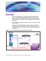
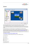
Overview
The MCS 2-server Sun Fire* V100 Solaris system is a small-scale
version of the Multimedia Communication Portfolio (MCP) system,
geared towards an environment with a maximum of 250 subscribers.
This system allows more effective cost management for smaller-sized
enterprises.
This document describes the installation of the 2-server Sun Fire V100
Solaris system.
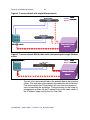
The 2-server Sun Fire V100 Solaris system must be connected to a
100-MB full-duplex Ethernet switch. The IP configuration consists of
one public IP address. The following figures show the possible network
configurations.
Figure 1 2-server network with redundant Ethernet switches
Ethernet switch
1
0
0
B
T
P
o
w
e
rc
a
b
le
Crossover/cascade
cable
SunFireV100
SunFireV100
Ethernet switch
MCS 2-server Sun Fire V100 Solaris Installation and Commissioning Guide
Protectedpower
source
Copyright © 2006 Nortel Networks
12
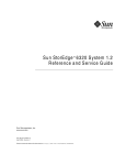
Figure 2 2-server network with single Ethernet switch
SunFireV100
1
0
0
B
T
P
o
w
e
rc
a
b
le
SunFireV100
Ethernet switch
Protectedpower
source
Figure 3 2-server network MAS Ad hoc audio conferencing with single Ethernet
switch
E
t
h
e
r
n
e
tS
w
it
c
h
1
0
0
B
T
M
X
3
0
5
IBMIB
X336
P
o
w
e
rc
a
b
le
P
r
o
t
e
c
t
e
d
P
o
w
e
r
S
o
u
r
c
e
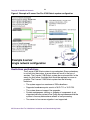
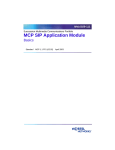
The rest of this document will refer to the example data in the figure that
follows. Print and refer to this example while executing this installation.
Print and complete the CSI datasheet with your own configuration to
assist in executing this installation. Configure the pc you are using for
management services with an IP address that is in the same subnet of
the IP address range used for the Sun Fire V100.
NN10364-301 MCS 5100 3.5 Standard 6.0 December 2006
Copyright © 2006 Nortel Networks
13
Figure 4 Example of 2-server Sun Fire V100 Solaris system configuration
Restrictions and limitations
The 2-server V100 Solaris system is non-redundant. Since redundancy
is not built into the system, a server failure will result in the loss of
services. The 2-server V100 Solaris system has a mirrored disk. In the
event of a disk failure, the failed disk should be replaced as soon as
possible. The 2-server V100 Solaris system has the following
limitations:
•
The system supports a maximum of 250 subscribers.
•
Supported conference ports consist of 30 G.711 or 10 G.729.
•
The system does not support live upgrades.
•
System maintenance, starting, or stopping of components is not
supported while the system is live. Doing any maintenance while the
system is live may have adverse effects on call processing.
•
Two-server-to-four-server migration is not supported.
MCS 2-server Sun Fire V100 Solaris Installation and Commissioning Guide
Copyright © 2006 Nortel Networks
14
MCS 5100 documentation
Refer to the MCS 5100 Network Deployment and Engineering Guide,
NN10313-191, that accompanies the MCS 5100 product and to your
customer-specific information (CSI) datasheet for your system
requirements.
For more information on component installation and commissioning
tasks, refer to the specific component documentation:
•
MCS 5100 Accounting Module Basics, NN10279-111
•
MCS 5100 SIP Application Module Basics, NN10259-111
•
MCS 5100 Database Module Basics, NN10267-111
•
MCS 5100 Management Module Basics, NN10268-111
•
MCS 5100 Provisioning Module Basics, NN10274-111
•
MCS 5100 Provisioning Client User Guide, NN42020-105
•
MCS 5100 H.323 Gatekeeper Basics, NN10280-111
•
Media Application Server Network Engineering and Deployment
Guide, NN10377-191
•
MCS 5100 Ad Hoc Audio Conferencing Service Guide,
NN10297-111
•
Media Application Server Meet Me Audio Conferencing Service
Guide, NN10303-111
•
Media Application Server - Music on Hold Service Guide,
NN10378-113
•
Media Application Server Announcements Service Guide,
NN10379-113
•
Media Application Server IM Chat Service Guide, NN10380-113
•
Media Application Server - Meet Me Audio Conferencing Quick
Reference, NN10283-001
•
MCS 5100 IP Client Manager Basics, NN10256-111
•
MCS 5100 Web Client Manager Basics, NN10278-111
•
MCS 5100 Interworking Guide, NN10372-111
•
MCS Backup and Recovery Guide, NN42020-502
•
MCS Accounting Common Call Scenarios Reference Guide,
NN10374-800
•
Provisioning Enhanced 911 User Guide, NN42020-132
NN10364-301 MCS 5100 3.5 Standard 6.0 December 2006
Copyright © 2006 Nortel Networks
15
•
MCS 5100 Fault Management: Alarm and Log reference,
NN10385-900
•
MCS 5100 Performance Management: OM reference ,
NN10386-700
MCS 2-server Sun Fire V100 Solaris Installation and Commissioning Guide
Copyright © 2006 Nortel Networks
16
NN10364-301 MCS 5100 3.5 Standard 6.0 December 2006
Copyright © 2006 Nortel Networks
Before you start the installation
ATTENTION
Make sure you install the latest software loads. Check with your
support team for the correct latest load.
Prerequisites
Have available your completed Customer-Specific Information (CSI)
datasheet. Refer to the MCS 5100 Network Deployment and
Engineering Guide, NN10313-191, that accompanies the MCS product
for CSI and system requirements. Make a copy of the CSI datasheet
from Appendix E of the MCS 5100 Network Deployment and
Engineering Guide (NN10313-191). Fill out the datasheet with relevant
information from your system administrator.
You must have read and understood all the Release Notes before the
installation begins.
Nortel Networks strongly recommends the use of high-speed data
network connectivity for optimum remote service capability. Without
broadband connectivity, remote service options are limited. Nortel
Networks recommends the Contivity Remote Access Solutions for this
function.
Nortel Networks also recommends following standard data center
conventions for having a Universal Power Supply (UPS) as the power
backup for the servers. For more information, refer to the MCS 5100
Network Deployment and Engineering Guide, NN10313-191, which
shows how to connect servers to two different UPS systems for
maximum uptime.
For power over Ethernet in the closet switches, Nortel Networks
recommends use of the Ethernet Switch 460 Power Over LAN layer 2
Ethernet switches.
MCS 2-server Sun Fire V100 Solaris Installation and Commissioning Guide
Copyright © 2006 Nortel Networks
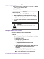
18
The procedures in this Guide assume that you are using the PuTTY
VT100 terminal emulator tool.
ATTENTION
To set up sessions, download from the web the PuTTY VT100
Emulator, a shareware configurator tool.
Download PuTTY from
www.chiark.greenend.org.uk/~sgtatham/putty/
Provide the following hardware:
•
Business Policy Switch 2000 (BPS 2000) or Layer-2 switch
•
One (1) cat-5 Ethernet cable that is used to connect the MRV LX
terminal server to the layer-2 switch.
•
PC (for management administration). Refer to Minimum and
recommended requirements for customer-provided PC on page 23.
ATTENTION
You must have access to the MCS network.
Make sure
•
There are no other maintenance or provisioning activities pending,
and no such activities are planned for the duration of the installation
procedures and follow-up soak period.
•
You have a detailed knowledge of your network’s configuration.
•
You have proficiency using UNIX operating system commands.
•
You have access and privileges to the network.
•
You have authority or immediate access to people with authority to
make decisions on any issues that may arise.
Acronyms
The following acronyms are referenced in this document:
•
lights out management (LOM)
•
Network Time Protocol (NTP)
•
customer-specific information (CSI)
NN10364-301 MCS 5100 3.5 Standard 6.0 December 2006
Copyright © 2006 Nortel Networks
19
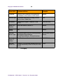
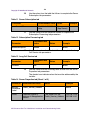
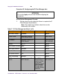
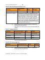
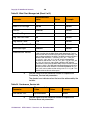
Key stroke symbols
The following key stroke symbols are used in this document.
When you are
asked to
You must...
Press Esc+2
Press Escape then press 2.
Navigate
Use the arrow keys to move up or down.
Select
Use the spacebar to select an item.
<Value in brackets>
Enter value indicated in brackets.
[Enter]
Press key indicated in brackets.
Text conventions used in this document
This document uses the following text conventions:
•
Bolded type is used to signify commands or buttons that you must
press to perform an action, for example, Apply.
•
Courier type is used to signify what appears on screen, for example,
Enter your password.
•
Italic type is used for emphasis, for special words, or for reference
information; for example, "Log in as root."
MCS 2-server Sun Fire V100 Solaris Installation and Commissioning Guide
Copyright © 2006 Nortel Networks
20
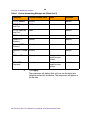
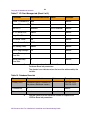
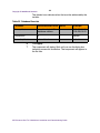
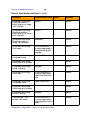
Server configuration
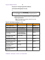
The following table shows the basic configuration of the 2-server V100
Solaris system.
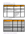
Table 1 2-server configuration
Configuration
Server type
Components
2-server V100
Solaris
Server1
Active System Manager
Active Accounting Manager
Primary database
Oracle Monitor
Server2
IPCM (S1)
Active Provisioning Module
Active SIP Application Module
Active WebClient Manager
iPlanetMonitor
UFTP Base Software
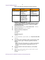
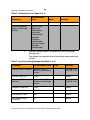
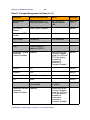
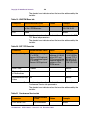
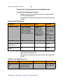
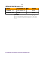
Loading disks
MCS 5100 Release 3.0 Base Platform System SoftWare Kit
NTVW01AJ contains multiple copies of the same CDs to allow
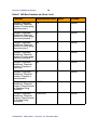
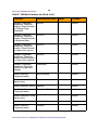
simultaneous installation across servers. See Table 2, Mapping of Kit
NTVW01BD disks to servers (with times), on page 21 for details. Nortel
Networks recommends that you install the same CDs on both servers
at the same time to reduce installation time.
As shown in Table 2, Mapping of Kit NTVW01BD disks to servers (with
times), Disks 1-5 have four copies each. Disk 6 only needs to go on
Server 1 (the server on which the Management and Accounting
Modules reside). There are six Oracle disks, with one copy, going on
Server 1(the server on which the Database Module resides).
NN10364-301 MCS 5100 3.5 Standard 6.0 December 2006
Copyright © 2006 Nortel Networks
21
MCS Base Platform System Software disks are loaded on the following
servers as indicated in Table 2, Mapping of Kit NTVW01BD disks to
servers (with times)
MCS Base Platform System
Software: Order code NTVW01BD
Approximate time
to install
Server 1
Server 2
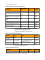
Table 2 Mapping of Kit NTVW01BD disks to servers (with times)
CD1 Disk Partitioning & Solaris OS
Kernel
45 minutes
X
X
CD2 Solaris OS Packages
15 minutes
X
X
CD3 Solaris Packages and Patches
90 minutes
X
X
CD4 MCP Installation &
Commissioning
20 minutes + disk
mirroring, 10
minutes
X
X
CD5 MCP Base Platform & 3rd Party
Software
30 minutes
X
X
CD6 MCP Application keycoded S/W
20 minutes
X
CD7 MCP Element Manager Console 15 minutes
Oracle disks 1-6
90 minutes
Total (approximate) time for each
server.
3.6 hours for each
server, plus 90
minutes Oracle
installation on
Database server
Management
PC
X
X
MCS 2-server Sun Fire V100 Solaris Installation and Commissioning Guide
Copyright © 2006 Nortel Networks
22
NN10364-301 MCS 5100 3.5 Standard 6.0 December 2006
Copyright © 2006 Nortel Networks
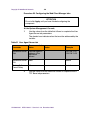
Minimum and recommended
requirements for customer-provided PC
Configure your management pc to have an IP address that is in the
same subnet of the IP address range used for your servers. Check your
pc vendor’s documentation to learn how to configure the PC’s IP
address.
Minimum and recommended requirements for the customer-provided
management PC include (assuming you are not running anything else
on the pc):
•
processor:
— minimum: 600 MHz Pentium-class or equivalent processor.
— recommended: 1.0 GHz (or higher) Pentium-class or equivalent
processor.
•
free RAM:
— minimum: 64MB of RAM. (This requirement is in addition to the
memory requirements of the operating system and other
concurrent applications.)
— recommended: 64MB of RAM. (This requirement is in addition to
the memory requirements of the operating system and other
concurrent applications.)
•
free hard disk space:
— minimum: 50MB (If the System Management Console is
installed on a drive other than drive C, then 50MB of free space
is required on that drive as well. In this case, the free 50MB on
drive C will not be used, but is required for the installation to
complete successfully.)
— recommended: 50MB (If the System Management Console is
installed on a drive other than drive C, then 50MB of free space
is required on that drive as well. In this case, the free 50MB on
drive C will not be used, but is required for the installation to
complete successfully.)
•
CD-ROM drive: required
MCS 2-server Sun Fire V100 Solaris Installation and Commissioning Guide
Copyright © 2006 Nortel Networks
•
mouse: required
•
Video Graphics Card:
24
— minimum: 640x480 @8bpp [256 colors] VGA
— recommended: 800x600 @16bpp [65,536 colors] VGA or better
•
sound card: not applicable
•
operating systems:
— minimum: Microsoft Windows 98(SE)/ME/2000/XP, or Microsoft
Windows NT 4.x with Service Pack 5 (SP5)
— recommended: Microsoft Windows 98(SE)/ME/2000/XP, or
Microsoft Windows NT 4.x with Service Pack 5 (SP5)
— network connectivity: Ethernet network card
— web browser with Microsoft Internet Explorer 6.0, or later version
— web browser with Netscape Communicator 7.0, or later version
— cookies: enabled
— Javascript: enabled
NN10364-301 MCS 5100 3.5 Standard 6.0 December 2006
Copyright © 2006 Nortel Networks
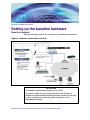
Setting up the baseline hardware
Baseline hardware
See the following figure for an overview of the hardware connectivity.
Figure 3 Hardware connections overview
ATTENTION
You need an uninterrupted power source (UPS).
If a power outage occurs, bring the server for the Database
Module into service before bringing the other servers into service.
If other servers do not come up, restart the server for the
Management Module.
MCS 2-server Sun Fire V100 Solaris Installation and Commissioning Guide
Copyright © 2006 Nortel Networks
26
Hardware required for the 2-server system consists of the following:
•
terminal server: 1 MRV LX-4008-101AC including
— Linux-based secure console standalone unit with 8 RS232 RJ45
ports
— internal V.90 modem and AC power
— software and documentation on CD-ROM
•
core servers: 2 Sun Fire V100 servers including
— 1 550-MHz UltraSPARC IIi Processor with 512-KB On-Chip L2
Cache
— 1-GB Memory
— 2 40-GB 7200 RPM IDE Disk (second disk for mirroring)
— CD-ROM
— 2 10/100-Mbit Ethernet and USB Ports
— System configuration card
— Solaris* 8 and LOMlite2 pre-installed
— two (2), cat-5 Ethernet cables for each V100 server (for a total of
four (4) ethernet cables)
Note: Each V100 server uses two (2) ethernet cables to
connect the V100 servers to the layer-2 switch.
— two (2) serial (RS232) cables for each V100 server (or a total of
eight (8) serial cables.)
Note: Serial cables are ordered with the MRV LX terminal
server.
– one (1) cable for Serial Port A (LOM)
– one (1) cable for Serial Port B
— Sun Fire V100 server documentation
NN10364-301 MCS 5100 3.5 Standard 6.0 December 2006
27
Copyright © 2006 Nortel Networks
•
Media Application Server: 1 IBM x336 (2 3.6 GHz Xeon, 1-GB RAM,
1 73-GB SCSI drive, Windows 2000)
•
Multimedia PC Clients
ATTENTION
Make sure you have
•
Business Policy Switch 2000 (BPS 2000) or Layer-2 switch
•
vendor documentation for configuring your Layer-2 switch
•
one (1) additional cat-5 ethernet cable to connect the MRV LX
terminal server to the layer-2 switch
•
a pc for the System Management Console, and access to the
network
WARNING
Static electricity could be harmful to the servers.
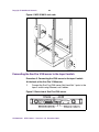
Setting up rack to mount hardware
Procedure 1 Setting up rack to mount hardware
At the rack,
1
Mount all equipment. Refer to the following diagram that displays
the mounting for the rack.
•
Mount Layer-2 switch.
•
Mount the MRV LX terminal server.
•
Mount Sun Fire V100s.
— Database/Management/Accounting server
— Application server
•
(optional equipment) Mount conference server. Refer to the
Media Application Server documentation for more
information.
•
(optional equipment) Mount gateway. Refer to
customer-specific gateway installation documentation.
Note: All MCS equipment is 19-inch rack mountable.
MCS 2-server Sun Fire V100 Solaris Installation and Commissioning Guide
Copyright © 2006 Nortel Networks
28
Figure 4 MCS 5100 19-inch rack
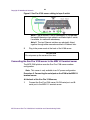
Connecting the Sun Fire V100 server to the layer-2 switch
Procedure 2 Connecting the V100 server to the layer-2 switch
At the back of the Sun Fire V100 server,
1
Connect the Sun Fire V100 server Net 0 and Net 1 ports to the
layer-2 switch using Ethernet, cat-5 cables.
Figure 5 Back view of Sun Fire V100 server
NN10364-301 MCS 5100 3.5 Standard 6.0 December 2006
Copyright © 2006 Nortel Networks
29
Figure 6 Sun Fire V100 server cabling to layer-2 switch
Note 1: Net 0 and Net 1 are for redundancy. It is preferable
that each Ethernet port get cabled to a different layer-2 switch,
if available, for maximum redundancy.
Note 2: The two Ethernet switches are physically linked
together through either cascade modules or Ethernet links.
2
Plug in the power cords at the back of the V100 server.
ATTENTION
Do not power up the server at this time.
Connecting the Sun Fire V100 server to the MRV LX terminal server
The MCS 5100 platform uses the Sun Fire V100 server medium
configuration.
Note: This server is only available in an AC power configuration.
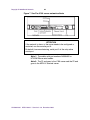
Procedure 3 Connecting the serial port on the V100 to the MRV LX
terminal server
At the back of the Sun Fire V100 server,
1
Connect the Sun Fire V100 server A/LOM serial port and Bserial port to the MRV LX terminal server:
MCS 2-server Sun Fire V100 Solaris Installation and Commissioning Guide
Copyright © 2006 Nortel Networks
30
Figure 7 Sun Fire V100 server network callouts
ATTENTION
If the network is down, or the server needs to be configured or
restarted, use the console port A.
By default from manufacturing, serial port A is the only active
serial port.
Note 1: The cables with part numbers A0500465 or
NTVW01IM are serial cables.
Note 2: The P1 end goes to the V100 server and the P2 end
goes to the MRV LX terminal server.
NN10364-301 MCS 5100 3.5 Standard 6.0 December 2006
Copyright © 2006 Nortel Networks
31
Figure 8 P1 and P2 custom cable connections to terminal server
See note
Note: This cable is only connected to configure the terminal server.
Following configuration, remove the cable.
MCS 2-server Sun Fire V100 Solaris Installation and Commissioning Guide
Copyright © 2006 Nortel Networks
32
NN10364-301 MCS 5100 3.5 Standard 6.0 December 2006
Copyright © 2006 Nortel Networks
Installing and accessing the MRV
LX-4000 series terminal server
The MRV LX terminal server allows the installer to access all the
servers simultaneously.
ATTENTION
For complete information on how to install, configure, and access
the MRV LX terminal server, refer to the MRV Communications,
Inc., LX Series Software Kit CD, particularly the "Getting Started
with the LX-4000 Series" and LX-4000 Quick Start Instructions
that come in the terminal server box, or go to www.mrv.com.
Procedure 4 Connecting the MRV LX terminal server cable to the
servers and management PC
At the terminal server,
1
Connect port 8 to the management PC using the console cable
and db9 connector that comes with the MRV LX terminal server.
Note: After the terminal server has been configured, the
connection between the management PC and the terminal
server is not needed, and the cable can be removed.
2
Connect the MRV terminal server 10 Base-T port to the layer-2
switch.
Refer to the Getting Started with the LX-4000 Series document
in the CD that comes with your terminal server for specific
information about the pinouts on your terminal server model.
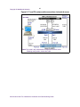
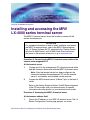
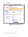
Procedure 5 Accessing the MRV LX terminal server
At the browser address field,
1
Type in the IP address of your MRV LX terminal server. The LX
Series Configuration Console page appears, as shown.
MCS 2-server Sun Fire V100 Solaris Installation and Commissioning Guide
Copyright © 2006 Nortel Networks
34
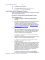
Figure 9 MRV Configuration Console window
2
Make sure you have the Java Plug-in installed.
3
When your browser connects to the terminal server, the Java
Security Warning window appears.
Figure 10 Java Security Warning pop-up window
NN10364-301 MCS 5100 3.5 Standard 6.0 December 2006
Copyright © 2006 Nortel Networks
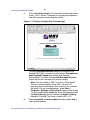
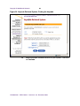
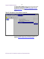
4
35
Click on Grant this session. The Java Security Warning window
closes. The LX Series Configuration Console page reappears,
now with the green console selection visible.
Figure 11 LX Series Configuration Console page
Choosing Encrypted Console means the Graphical User
Interface (GUI) will run slower, but with security. Encrypted and
Not Encrypted Console also require Java Runtime
Environment 1.4 or later. Choosing Not Encrypted Console
means the GUI will run faster, but without security.
Note: The Java cache in JRE 1.4 is set to ON by default.
There is a known problem within JRE 1.4.0 and 1.4.1
regarding cache functionality, which requires you to disable
the cache. On your management pc, select Start->
Programs-> Settings-> Control Panel, open the Java Plugin
1.4.0 icon, and click the Cache tab. At the Cache window, click
theClear Cache button and uncheck the Enable Caching
checkbox. Click OK. This issue is fixed in JRE 1.4.2.
5
Select Encrypted or Not Encrypted and then select Load. A
login window appears.
MCS 2-server Sun Fire V100 Solaris Installation and Commissioning Guide
Copyright © 2006 Nortel Networks
36
Figure 12 Login window
6
Enter your Username and Password, and click Login.
Note: By default, authentication is done against the local user
database. To start, use the known username InReach and
password access.
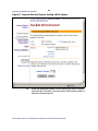
7
If you log in as a user, the following window appears.
NN10364-301 MCS 5100 3.5 Standard 6.0 December 2006
Copyright © 2006 Nortel Networks
37
Figure 13 User login window
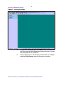
8
To log in as a superuser, click the Admin button on the tool bar
and log in with the default Superuser password system. You can
now configure the unit at the GUI.
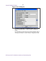
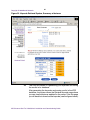
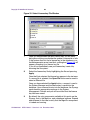
9
Click on the menus on the left side of the window. For example,
selecting Ports: Async opens the Async ports window.
MCS 2-server Sun Fire V100 Solaris Installation and Commissioning Guide
Copyright © 2006 Nortel Networks
38
Figure 14 Example: selecting Ports: Async
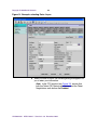
a When you click on a port, the following dialog box appears for
you to enter your information.
Note: In the TCP window (see Figure 15), ensure that
both the Telnet CR Filtering radio button, and the Telnet
Negotiations radio button are Enabled.
NN10364-301 MCS 5100 3.5 Standard 6.0 December 2006
Copyright © 2006 Nortel Networks
39
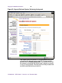
Figure 15 Port 19 dialog box
For details on using the IP Configuration Menu, refer to “Using
the IP Configuration Menu” in the LX-Series Configuration
Guide.
For information on how to boot your unit from defaults, refer to
“Booting from Defaults” in the LX-Series Configuration Guide.
MCS 2-server Sun Fire V100 Solaris Installation and Commissioning Guide
Copyright © 2006 Nortel Networks
40
Procedure 6 Connecting through the server to the MRV LX
terminal server
At the management pc,
1
ATTENTION
MRV Communications recommends that you change the default
password for the user’s MRV LX terminal server before you put
the unit on a network. For more information, refer to Changing the
password defaults on page 40.
Use the following procedure to access the command line
interface port from a dumb terminal attached to an LX Series
serial port, which is set for access local or dynamic:
a Hit the return key several times to autobaud (if autobaud is
enabled) the port and get the login prompt.
b Enter your login name. The default is InReach.
c Enter your password. The default is access.
Procedure 7 Changing the password defaults
At the management pc,
1
The default password for the MRV LX terminal server user is
access. If an unauthorized user knew this username/password
combination, that user could log on to your unit. For this reason,
you should change the user’s password to something other than
access.
The default Superuser password is system. To reduce the risk of
an unauthorized user gaining access to the Superuser
Command Mode, MRV recommends that you change this
password to something other than system.
To change the user-level password, access the Configuration
Command Mode.
2
Access the Subscriber Command Mode for the subscriber by
entering the subscriber command with InReach as the
command argument; for example: Config:0 >>subscriber
InReach
3
Enter the password command at the Subs_InReach >>
prompt.
NN10364-301 MCS 5100 3.5 Standard 6.0 December 2006
Copyright © 2006 Nortel Networks
41
4
Enter a new user password at the Enter your NEW
password: prompt. The password will be displayed as
asterisks.
5
Re-enter the new user password at the Re-Enter your NEW
password: prompt. The password will be displayed as
asterisks.
6
To change the superuser password for the unit, do the following:
a Access the Configuration Command Mode.
b Enter the password command at the Config:0 >> prompt.
c Enter a new superuser password at the Enter your NEW
password: prompt. The password will be displayed as
asterisks.
d Re-enter the new superuser password at the Re-Enter
your NEW password: prompt. The password will be
displayed as asterisks.
Procedure 8 Accessing the MRV LX terminal server
At the management pc,
1
Select Start -> Programs -> Accessories -> Communications
-> HyperTerminal.exe
2
Name the HyperTerminal Session: termserv [Enter]
3
Ensure that the appropriate COM port is set and that the
terminal emulation is set to VT100.
Note 1: You may be asked for the following parameters:
•
9600 baud rate
•
8 data bits / second
•
parity - None
•
stop bit - 1
•
Flow control - None
Note 2: Press Enter until you receive a log-in prompt. You
may need to press Enter several times before the prompt
appears.
4
Log in to the HyperTerminal: access [Enter]
Note: The letters do not appear when you type them. You are
typing them in blind.
5
Enter your username: admin [Enter]
6
To change security at the prompt, type set priv [Enter]
MCS 2-server Sun Fire V100 Solaris Installation and Commissioning Guide
Copyright © 2006 Nortel Networks
42
7
Enter your password: system [Enter]
8
Define server ip address <IP address of the terminal server>
[Enter]
9
Define server ip subnet mask <ip-address of the subnet
mask> [Enter]
10
Define server ip primary gateway address <ip address of the
primary gateway> [Enter]
11
Define port:<select port from range 1-18> telnet newline
filtering cr [Enter]
Note: Type a range [1-18] for every port the Sun Fire V100
server is connected to.
12
Define port for use with SMDI: Define port 19 telnet newline
filtering none
Note: You can verify the ports with the command:show ports
1-19 telnet chara [Enter]
13
Save your changes.
14
Log out.
Note: Using the command define saves the configuration.
15
To kill a session on a port, type: logout port 12 [Enter]
Procedure 9 Connecting a server to the MRV LX terminal server
ATTENTION
The procedures in this document assume that you are using
PuTTY. It is suggested that you download from the web, PuTTY
VT 100 Emulator, a freeware configurator tool to set up sessions.
Download PuTTY from
www.chiark.greenend.org.uk/~sgtatham/putty/
At the management pc,
1
Connect a cat-5 Ethernet cable from the management PC to the
layer-2 switch.
2
Launch PuTTY.
Note: Refer to the customer-specific information datasheet to
enter the MRV LX terminal server IP address and the port
number.
3
In the hostname field, enter <IP address of the MRV LX
terminal server>
NN10364-301 MCS 5100 3.5 Standard 6.0 December 2006
Copyright © 2006 Nortel Networks
4
43
For port, enter <the port number which corresponds to A/LOM
(Serial A) on the V100 and the MRV LX terminal server>.
Note 1: For LOM ports, use terminal server ports 2100-2400
(physical ports 1-4). For Serial ports, use terminal server ports
3100-3400 (physical ports 11-14).
The port number identifies the location of the target host. This
value is based on the following formula: 2000 + (Port number
physically connected on the MRV LX terminal server x 100).
For example, if the target host is connected to port 9 of the
MRV LX terminal server, then the port number would be 2900.
Port 12 is the port on the back of the MRV LX terminal server
that translates to 3200.
Note 2: Once the connection is established to the target host,
the communication between the user and the component is
treated exactly like a console connection.
MCS 2-server Sun Fire V100 Solaris Installation and Commissioning Guide
Copyright © 2006 Nortel Networks
44
NN10364-301 MCS 5100 3.5 Standard 6.0 December 2006
Copyright © 2006 Nortel Networks
Powering on the servers
Procedure 10 Powering on the servers
At the server,
1
ATTENTION
Do not have any bootp servers on the same subnet of the system.
If there is such a server, disconnect the LAN interface cable from
the system subnet.
Turn power on to the server.
2
If the system boots up, log into the server as root.
3
Type init 0 [Enter].
This will bring you to the boot (>ok) prompt. If the system does
not have Solaris installed, it will power up to the >ok prompt. You
may have to send a break to get the >ok prompt. The servers will
more than likely boot up to a Solaris System Identification
screen. Do not answer those questions. Send a break to get to
the >ok prompt so you can then boot from the CD-ROM.
Procedure 11 Power on to get the >ok prompt
At the management pc,
1
If you are using PuTTY, click the program icon in the upper left
PuTTY title bar to access PuTTY’s pull-down menu.
2
Mouse over the telnet command menu item to access additional
drop-down menu options.
3
Select Break to send the break command from the PuTTY
session.
MCS 2-server Sun Fire V100 Solaris Installation and Commissioning Guide
Copyright © 2006 Nortel Networks
4
46
The >ok prompt appears.
ATTENTION
If you do not use PuTTY, use the appropriate key sequence to
send a break to the server to get an >ok prompt.
NN10364-301 MCS 5100 3.5 Standard 6.0 December 2006
Copyright © 2006 Nortel Networks
Installing Disks 1 to 3
ATTENTION
Refer to the customer-specific information datasheet for host
name, IP addresses, subnet masks, and so on.
ATTENTION
For installation on a brand-new machine, connect through the
terminal server to the A/LOM port until after you have installed
CD5. Then log out.
Log back in through the terminal server to B/Serial port for the
rest of the installation.
For installations on machines that have already had a system
installed, just remain on the B/Serial port.
ATTENTION
The first time you connect to a server, it generates a PuTTY
Security Alert. Select Yes from the dialog box that appears. You
will then be asked to log in. Use your nortel account and enter the
password you have set. The passwords are time sensitive and will
expire after the set number of days.
Installing CD1
Approximate time estimate = 45 minutes
Procedure 12 Installing CD1
At the management pc,
1
Place CD1 in the CD-ROM drive.
MCS 2-server Sun Fire V100 Solaris Installation and Commissioning Guide
Copyright © 2006 Nortel Networks
48
2
ATTENTION
Make sure you put spaces before and after the hyphen: boot
[space] cdrom [space] - [space] install.
At the >ok prompt, boot the system: boot cdrom - install
[Enter]
Note 1: For instructions on how to get to the >ok prompt, see
Powering on the servers on page 45.
Note 2: You must wait several minutes before information
begins to appear.
Select a Language
3
To select zero [0] for English,
0 [Enter]
Select a locale
4
To select zero [0] for English,
0 [Enter]
What type of terminal are you using?
5
Select three [3] for DEC VT100,
3 [Enter]
Note: The following message is displayed: The system is
coming up. Please wait.
ATTENTION
Ignore any time zone and syntax errors you receive. You will set
the time zone and additional information in the next procedure.
Solaris Installation Program Page
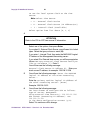
1
Press Esc, then press the number 2 [Esc+2] to continue.
Note: If you are using a direct console connection to the SUN
terminal, use the F2 key.
2
Press Esc+2 to continue.
NN10364-301 MCS 5100 3.5 Standard 6.0 December 2006
Copyright © 2006 Nortel Networks
49
Network Connectivity/Networked
3
Accept the default Yes by pressing Esc+2 to continue.
DHCP/Use DHCP
4
Accept the default No by pressing Esc+2 to continue.
Primary Network Interface /Primary Network Interface
5
Accept the default dmfe0 interface by pressing Esc+2 to
continue.
Host name/Host name
6
Enter the host name of the server, for example: micromgmt
Note 1: Host name cannot start with a number. Host names
must be at least two characters and can contain alphanumeric
characters and minus signs (-).
Note 2: Host names must be unique within your domain.
Creating a duplicate host name will cause problems on the
network after you install Solaris.
Press Esc+2 to continue.
IP Address
7
ATTENTION
Make sure you enter the machine logical IP address for this
system. It must be unique and follow your site’s address
conventions.
Enter the machine logical IP address.
Example: 120.120.13.25
Press Esc+2 to continue.
Subnets/System part of a subnet
8
Accept the default Yes by pressing Esc+2 to continue.
MCS 2-server Sun Fire V100 Solaris Installation and Commissioning Guide
Copyright © 2006 Nortel Networks
50
Netmask/Netmask
9
ATTENTION
Do not accept the default unless you are sure it is correct for your
subnet.
Enter the subnet mask, for example: 255.255.255.0.
Press Esc+2 to continue.
IPv6/Enables IPv6
10
ATTENTION
IPv6 is not supported.
Accept the default No.
Press Esc+2 to continue.
There is a slight delay between screens. Please wait.
Confirm information
11
Ensure all fields are filled correctly. Press Esc+2 to continue.
Press Esc+4 if you need to change anything.
Configure Security Policy
12
Confirm the Kerberos information by accepting the default No.
Press Esc+2 to continue.
Confirm information
13
Ensure all fields are filled correctly. Press Esc+2 to continue.
You will see the message Starting remote procedure
call (RPC) services: sysidnsName Service.
Name Service/Name Service
14
Confirm the name service information by using the down arrow
key to navigate to None. Press the Return key. Press Esc+2 to
continue.
NN10364-301 MCS 5100 3.5 Standard 6.0 December 2006
Copyright © 2006 Nortel Networks
51
Continuing the process
15
Confirm your information. Ensure all fields are filled correctly.
Press Esc+2 to continue.
Press Esc+4 if you need to change anything.
16
At the Regions prompt, select the country where the system is
going to be deployed. Use the arrow keys to navigate to the
required country and press the spacebar to mark your choice.
Ignore time zone syntax errors.
Press Esc+2 to continue.
17
At the Time zones prompt, select the time zone (for example,
Central for the Richardson, Texas, area) where the system is
going to be deployed. Use the arrow keys to navigate to the
required time zone and press the spacebar to mark your choice.
Press Esc+2 to continue. Please wait for the next prompt.
18
At the Date and time prompt, set up the date and time.
Press Esc+2 to continue.
19
Confirm information. Ensure all fields are filled correctly.
Press Esc+2 to continue and wait for the message: System
identification is completed.
20
ATTENTION
Make the following selection very carefully. If you make a mistake
at this point, you will need to start over, beginning with Powering
on the servers on page 45. The selection of the number depends
on the configuration type.
You will see the following message. Select the 2-server Micro
Configuration (1) option, then press Enter:
*********************************************
1) 2-server Micro Configuration
2) 4 or 4+ Standard Configuration
**********************************************
You will see the message Creating disk profile for
standard <number of servers> server system.
MCS 2-server Sun Fire V100 Solaris Installation and Commissioning Guide
Copyright © 2006 Nortel Networks
52
21
ATTENTION
Make the following selection very carefully. If you make a mistake
at this point, you will need to start over, beginning with Powering
on the servers on page 45. The selection of the number depends
on the server type.
You will see the following message:
*********************************************
Choose Application configuration:
1) AppSvr/IPCM/Websvr/WCM
2) Management/Accounting/Oracle/DB
**********************************************
Select your required server type, then press Enter.
Note: Select option 1 for the IPCM, SIP Application Module,
Web Client Manager, Provisioning Module, Web Client
Manager, and H.323 Gatekeeper.
You will see the message Creating disk profile for
<selected server>.
22
The install script will begin executing. The system will reboot
upon completion of the install script. Wait until you receive the
login prompt.
23
You will be prompted to type in the root password twice. The
password will not appear on the screen when you type. If you do
not want a root password, press Enter twice. Press Enter to
continue.
Note: The CD will eject from the CD-ROM. The system then
requests that you insert CD2.
ATTENTION
If you are not prompted for CD2, contact support.
Installing CD2
Approximate time estimate = 15 minutes
NN10364-301 MCS 5100 3.5 Standard 6.0 December 2006
Copyright © 2006 Nortel Networks
53
Procedure 13 Installing CD2
At the management pc,
1
Place CD2 in the CD-ROM drive and press Enter. You will see a
number of messages requiring no specific answer. Press Enter
following each one.
2
You will then see the following message: What type of
installation are you performing? 1=Typical;
2=CustomType 1 and press Enter.
3
You will then see the following message: Ready to Install:
Install Now, Start Over, Exit Installation
Type 1 for Install Now and press Enter.
4
Press Enter several more times to complete the License
Agreement. Enter Y to accept the license.
Note: You will now see a progress bar showing percent of
installation completed.
5
You will then be asked to choose 1 for Live Install or 2 for Done.
Accept the default 2-Done by pressing Enter.
Note 1: CD2 will eject from the CD-ROM drive when
installed.
Note 2: The system will reboot and come up requesting that
you insert MCS Base Platform System Software CD3.
ATTENTION
If you are not prompted for CD3, contact support.
Installing CD3
Approximate time estimate = 90 minutes
MCS 2-server Sun Fire V100 Solaris Installation and Commissioning Guide
Copyright © 2006 Nortel Networks
54
Procedure 14 Installing CD3
At the management pc,
1
ATTENTION
Wait for the login prompt to appear. The script will execute after
you press Enter.
Place CD3 in the CD-ROM drive and press Enter at the prompt.
The installation will continue. Please wait. The system will
prompt you for the next step.
2
Log in as root. [Enter]
3
Enter your <customer-specific password> [Enter]
Note 1: CD 3 will eject from the CD-ROM when installed.
Note 2: You will be prompted to insert CD4.
ATTENTION
If you are not prompted for CD4, contact support.
NN10364-301 MCS 5100 3.5 Standard 6.0 December 2006
Copyright © 2006 Nortel Networks
Installing Disk 4
ATTENTION
The following sections describe installing CD4 according to the
specific server type. Please note that there are some small, but
very important, differences in the installation of the two types of
servers (database/accounting/management or application
server).
Database/Accounting/Management server (DBSvr, AcctMgr,
MgmtSvr)
Approximate time estimate = 30 minutes
Procedure 15 Installing CD4
At the management pc,
1
Place CD4 in the CD-ROM drive and press Enter to continue.
Wait until you see the following statement appear:
”You are now configuring the NTP time source for
this server. The servers which run the
Management and Accounting service will be the
source. You will need to provide the Machine
Logical IP Address of each server. If running
simplex mode, provide the same address twice.”
2
Press Enter to continue.
3
You will see the following message:
The Management server requires an external
clock.
Select External Clock for time source external
to the Management server.
Select Internal Clock for the Managment server
MCS 2-server Sun Fire V100 Solaris Installation and Commissioning Guide
Copyright © 2006 Nortel Networks
56
to use the local system clock as the time
source.
Note: Select Time Source
•
X - External Clock Device
•
E - External Clock Source {IP Address(es)}
•
I - Internal Clock (Unreliable)
Select option from list above [E, I, X]
4
ATTENTION
Refer to the CSI for NTP time source IP information.
Select one of the options, then press Enter.
If you select X - External Clock Source, you will see a list of clock
types. Select the type you have or none (99).
If you enter I - Internal Clock, then enter the MACHINE Logical
IP Address of the Management/Accounting server:
If you select E for External time source, you will be prompted as
follows: How many external clock sources would you
like to reference [1]? Enter 1.
You will then see the following message:
External Clock Source IP Address #1: Enter your
clock source IP address, for example: 120.120.12.220
5
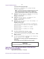
You will see the following message: "Enter the MACHINE
logical IP address of the other Accounting
Server."
Enter the <primary machine logical IP address of
the other accounting server> [Enter]
Example: 120.120.13.22
6
You will see the following message:
You have chosen to configure NTP as follows:
Type of server: Management
Using external Time Source(s): 120.120.12.220
NTP SOURCE (Accounting IP address): <ex:
120.120.13.22>
Is the above configuration correct (y/n):
Select Y to continue or N to change.
NN10364-301 MCS 5100 3.5 Standard 6.0 December 2006
Copyright © 2006 Nortel Networks
57
7
Press Enter to continue.
8
You will see the following statement:
”You are now configuring IPMP (Multipathing)"
”Please have the Database Server Physical IP
addresses and the Machine Logical IP address
ready. Have 6 IP addresses that can be used as
ping buddies." Recommendations for ping buddies
are provided.
9
Press the Enter key to continue.
10
When you see the IP multipathing configuration for Sun Solaris
information appear, press Enter to accept it or type in a preferred
setting. The default failover timeout is set to 1000mSec.
11
Enter the primary machine physical IP address for the dmfe0
interface: <Physical IP address of the dmfe0
interface> [Enter]
Example: 120.120.13.20
12
Enter the secondary machine physical IP address for the dmfe1
interface:
<Physical IP address of the dmfe1 interface>
[Enter]
Example: 120.120.13.21
13
Enter the <machine logical IP addresses of the
servers> that are the ping targets.
Note: Do not enter the IP address of the server you are
working on.
IP Multipathing needs a set of reliable hosts to ping against.
Select a set of three IP addresses in this subnet that belong to
reliable nodes (such as fault tolerant servers). Select the three
nodes from the following list, in order of preference:
For IPMP GROUPS:
•
Machine Logical IP address of the database server
•
Machine Logical IP address of the Management server
•
Machine Logical IP address of the CAM server
•
BPS stack IP address
•
Other optional devices (PRI Gateway host)
Provide between two and six ping targets or each IPMP group
for proper IPMP failover reliability. Enter the address "0.0.0.0" to
indicate list is complete, if entering less than six targets.
MCS 2-server Sun Fire V100 Solaris Installation and Commissioning Guide
Copyright © 2006 Nortel Networks
58
Enter ping target #1: 120.120.13.25
Enter ping target #2: 120.120.13.1
Enter ping target #3: 0.0.0.0
Note: Do NOT use this server's own IP address as a ping
target.
Press Enter after each IP address.
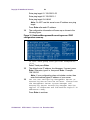
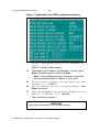
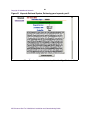
14
The configuration information will come up as shown in the
following figure:
Figure 16 Database/Management/Accounting server IPMP
configuration summary
Is this IPMP group configuration acceptable?
(Y/N)
Select Y and press Enter.
15
The default route IP address should appear. If correct, press
Enter. Otherwise, type it in, then press Enter. Example:
120.120.13.1
Note: If your configuration does not include a router, then
enter the machine logical IP address of your server.
16
You are now configuring Management Server or
Accounting Server Service Failover. Please have
the Management Server System Manager and
Accounting Server Accounting Manager Service
Logical IP addresses and the Machine Logical IP
addresses ready.
Press Enter to continue.
NN10364-301 MCS 5100 3.5 Standard 6.0 December 2006
Copyright © 2006 Nortel Networks
59
You will see the following message:
Obtaining IP Addresses for SysMgr/AcctMgr
Failover Operation
Note: If you don't have plan to configure the failover service,
type in the same primary service logical IP address and
primary machine logical IP address or type 0.0.0.0 instead.
17
Enter the <Machine Logical IP Address of the other
MgmtSvr> (in dot-notation format).
Example: 120.120.13.22
18
Enter the <service logical IP address of the
SysMgr> (in dot-notation format).
Example: 120.120.13.22
19
Enter the <service logical IP of the AcctMgr> (in
dot-notation format).
Example: 120.120.13.22
”You have entered the following IP addresses:
Machine Logical IP Address of the other MgmtSvr:
120.120.13.22
Service Logical IP Address of SysMgr:
120.120.13.22
Service Logical IP Address of AcctMgr:
120.120.13.22
20
Is this information correct? (y/n)
If the information is correct, press Y and Enter.
21
You are now configuring the Syslog daemon. Press
Enter to continue.
22
Is this the Redundant Configuration Accounting
Server Machine [Y/N]? Select N.
The system will now reboot and come up requesting that you
insert CD5.
CD4 will eject from the CD-ROM drive when installed.
ATTENTION
If you are not prompted for CD5, contact support.
Application servers (SIP Application Module, IPCM, Web Client
Manager, Provisioning Module)
Approximate time estimate = 15 minutes
MCS 2-server Sun Fire V100 Solaris Installation and Commissioning Guide
Copyright © 2006 Nortel Networks
60
Procedure 16 Installing CD4
At the management pc,
1
Place CD4 in the CD-ROM drive and press Enter to continue.
WAIT until you see the following statement appear:
”You are now configuring the NTP time source for
this server. The servers which run the
Management and Accounting service will be the
source. You will need to provide the Machine
Logical IP Address of each server. If running
simplex mode, provide the same address twice.”
2
Press Enter to continue.
3
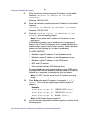
You will see the following message: "NTP Source 1: Enter
the MACHINE Logical IP Address of the Management
Server:
Enter the IP address, for example: 120.120.13.22
4
You will see the following message: "NTP Source 2: Enter
the MACHINE Logical IP Address of the Accounting
Server:
Enter the IP address, for example: 120.120.13.22
5
You will see the following message:
You have chosen to configure NTP as follows:
Type of server: Application
NTP SOURCE (Management IP address):
120.120.13.22
NTP SOURCE (Accounting IP address):
120.120.13.22
Is the above configuration correct (y/n):
Select Y to continue or N to change.
6
Wait until you see the following message:
You are now configuring IPMP (Multipathing)
Please have the Application Servers (Appsvr,
IPCM, WebSvr, WebClientMgr) Physical IP
addresses and the Machine Logical IP address
ready. Have 6 IP addresses that can be used as
ping buddies. Recommendations for ping buddies
are provided.
7
Press Enter to continue.
8
When you see the IP multipathing configuration for Sun Solaris
information appear, press Enter to accept it or type in a preferred
setting. The default failover timeout is set to 1000mSec.
NN10364-301 MCS 5100 3.5 Standard 6.0 December 2006
Copyright © 2006 Nortel Networks
9
61
Enter the primary machine physical IP address for the dmfe0
interface: <Physical IP address of the dmfe0
interface>
Example: 120.120.13.23
10
Enter the secondary machine physical IP address for the dmfe1
interface:
<Physical IP address of the dmfe1 interface>.
Example: 120.120.13.24
11
Enter the <machine logical IP addresses of the
servers> that are the ping targets.
Note: Do not enter the IP address of the server you are
working on.
IP Multipathing needs a set of reliable hosts to ping against.
Select a set of three IP addresses in this subnet that belong to
reliable nodes (such as fault tolerant servers). Select the three
nodes from the following list, in order of preference:
For IPMP GROUPS:
•
Machine Logical IP address of the database server
•
Machine Logical IP address of the Management server
•
Machine Logical IP address of the CAM server
•
BPS stack IP address
•
Other optional devices (PRI Gateway host)
Provide between two and six ping targets or each IPMP group
for proper IPMP failover reliability. Enter the address "0.0.0.0" to
indicate list is complete, if entering less than six targets.
Note: Do NOT use this server's own IP address as a ping
target.
12
Press Enter after each IP address, for example: 0.0.0.0
[Enter] (This is the third ping target machine logical IP
address.).
Example
Enter ping target #1: 120.120.13.22[Enter]
Enter ping target #2: 120.120.13.1[Enter]
Enter ping target #3: 0.0.0.0 [Enter]
Note: 0.0.0.0 ends the ping target list.
13
You will see the configuration summary appear as shown in the
following figure:
MCS 2-server Sun Fire V100 Solaris Installation and Commissioning Guide
Copyright © 2006 Nortel Networks
62
Figure 17 Application server IPMP configuration summary
Is this IPMP group configuration acceptable?
(Y/N)
Select Y to accept or N to change.
14
The default route IP address should appear. If correct, press
Enter. Otherwise, type it in, then press Enter.
Note: If your configuration does not include a router, then
enter the machine logical IP address of your server.
15
Do you intend to deploy the Web Server to this
machine (y,n)? Enter Y.
16
You are now configuring the Syslog Daemon. Press
Enter to continue.
17
Does the Management Server have a SysMgr Service
Logical IP Address [Y/N]? Select N.
The system will now reboot.
ATTENTION
If you are not prompted for CD5, contact support.
NN10364-301 MCS 5100 3.5 Standard 6.0 December 2006
Copyright © 2006 Nortel Networks
Installing Disk 5 (all servers)
Approximate time estimate is 30 minutes.
Procedure 17 Installing CD5
At the management pc,
1
Place CD5 in the CD-ROM drive, on the server, and press Enter
at the prompt.
Note 1: CD5 will eject from the CD-ROM when installed.
Note 2: For Management/Accounting servers, you will be
prompted for CD6. Refer to Installing Disk 6
(MgmtSvr/AcctMgr only) on page 67 for instructions.
Application/IPCM servers (AppSvr/IPCM) will reboot.
2
ATTENTION
On a brand-new machine, only the A/LOM port is available until
after CD5 completes. Once CD5 has completed, log out of the
A/LOM port.
Log back in through the terminal server to the B/Serial port for the
rest of the installation.
For installations on machines that have already had a system
installed, just remain on the B/Serial port.
After the AppSvr/IPCM reboot, log into these servers (using the
B/Serial port) and change the passwords for the sysadmin, root,
and nortel users.
Change the passwords on the MgmtSvr/AcctMgr server after
CD6 (not CD5).
MCS 2-server Sun Fire V100 Solaris Installation and Commissioning Guide
Copyright © 2006 Nortel Networks
64
NN10364-301 MCS 5100 3.5 Standard 6.0 December 2006
Copyright © 2006 Nortel Networks
Enabling or disabling the automatic
mount
Use the following procedure if you need to use the CD-ROM
auto-mount after installation of CD5. Execute this procedure on the
MgmtSvr (Server1).
ATTENTION
Keep this procedure for future use.
Procedure 18 Enabling or disabling the CD-ROM auto-mount
At the management pc,
1
The system disables volmgt by default after CD5 is installed. To
toggle it back on to install additional CDs, follow this step.
Log in as root from the console and type the following command:
/etc/init.d/volmgt start
2
When you finish mounting the additional disk(s), remember to
disable the volume manager for better security. To disable it, use
the following command: /etc/init.d/volmgt stop
MCS 2-server Sun Fire V100 Solaris Installation and Commissioning Guide
Copyright © 2006 Nortel Networks
66
NN10364-301 MCS 5100 3.5 Standard 6.0 December 2006
Copyright © 2006 Nortel Networks
Installing Disk 6 (MgmtSvr/AcctMgr
only)
ATTENTION
CD6 must be installed on the MgmtSvr and on the AcctMgr
machines only. If you do not install CD6, you will not be able to
deploy or start the secondary MgmtSvr or AcctMgr.
Approximate time estimate = 30 minutes
Procedure 19 Installing CD 6
At the management pc,
1
Place CD6 in the CD-ROM drive, on the server, and press Enter
at the prompt.
Note: CD6 will eject from the CD-ROM when installed.
2
After the reboot, log in (using the B/Serial port) and change the
passwords for the sysadmin, root, and nortel users.
MCS 2-server Sun Fire V100 Solaris Installation and Commissioning Guide
Copyright © 2006 Nortel Networks
68
NN10364-301 MCS 5100 3.5 Standard 6.0 December 2006
Copyright © 2006 Nortel Networks
Installing Oracle 9.2.0.4 on the database
server
The procedures to install Oracle 9 on the DBSvr include storing Oracle
9 CDs 1-6 to your local hard drive. Refer to the section that follows.
Approximate time for loading Oracle 9 = 90 minutes
ATTENTION
Refer to the CSI datasheet for such items as the hostname, IP
addresses, and subnet masks.
ATTENTION
Perform these steps on all servers in parallel if multiple CDs are
available.
Installing Oracle 9.2.0.4
Procedure 20 Installing Oracle 9.2.0.4 on the database server
(DBSvr)
At the management pc,
1
Use PuTTY to connect to the database server using Serial port
B, which connects to the LX terminal server.
Log in as root to the database server.
2
Enter your <customer-specific password>.
3
Insert Oracle 9.2.0.4 CD 1 into the CD-ROM drive on the server.
4
cd [ space] /cdrom/cdrom0 [Enter]
MCS 2-server Sun Fire V100 Solaris Installation and Commissioning Guide
Copyright © 2006 Nortel Networks
70
5
ATTENTION
Make sure you put a space before the ending slash (/) in step 5.
cp [ space] Install_CD_to_Disk [ space] / [Enter]
6
cd [ space] / [Enter]
7
./Install_CD_to_Disk [Enter]
8
Storing data from CDs to the /IMS/ora_cds
directory [Y]?: Select Y [Enter]
9
Please insert Oracle Disks [2-6] into the CD-ROM drive [Enter]
Note: You will receive the following prompts for each CD
entered:
Copying files from CDROM to /IMS/ora_cds/Disk
[1-6]
Performing check sum on /IMS/ora_cds/Disk
[1-6]
10
ATTENTION
Contact support if you do not receive the following response:
Check sum Oracle Disk [1-6] passed for each
Oracle CD inserted into the CDROM.
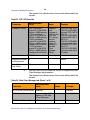
ATTENTION
In step 10 you will enter the hostname twice. The
sec_db_hostname is the same as the pri_db_hostname for a
42-server non-redundant configuration.
NN10364-301 MCS 5100 3.5 Standard 6.0 December 2006
Copyright © 2006 Nortel Networks
71
Refer to this table when entering the following command:
Prompt
Definition
Enter
pri_db_hostname
There is only one
hostname for a
24-server
configuration.
Hostname of the
database server, for
example,
micromgmtDBSvr.
sec_db_hostname
Since there is no
secondary server,
enter again the
pri_db_hostname
(Hostname of the
database server).
Re-enter hostname of
the database server.
cd [space] /IMS/ora_cds/Disk1 [Enter]
./Oracle_Install PRIMARY <primarydb-hostname> [space]
<secondarydb-hostname>[space] | [space] tee [space]
/tmp/oracleinstall.log
11
Enter the password oracle at the Oracle prompt. [Enter]
12
Retype the password: oracle [Enter]
13
Select the database configuration:
1) Enterprise
2) Carrier
Accept the default [1]
[Enter]
14
Is the database replicated [N]? Accept the default [N]
[Enter]
15
You will then see a confirmation screen. If the information on the
screen is correct, type Y. Otherwise, type N and make the
changes.
Note: At this point, the program runs a check sum and untars
the files to the local directory. Approximate time: 30 - 45
minutes.
16
Accept the default of the local bin directory: [/usr/local/bin]:
[Enter]
17
Removing Disk1,Disk2,Disk3,Disk4,Disk5,Disk6
from /IMS/ora_cds [Y]?:
Y [Enter]
MCS 2-server Sun Fire V100 Solaris Installation and Commissioning Guide
Copyright © 2006 Nortel Networks
72
Failing to answer Y will cause the system to raise a disk space
alarm on the SysMgr screen for the DBSvr.
You will see the message: Removing Disk 1, Disk2,
Disk3, Disk4, Disk5, Disk6 from /IMS/ora_cds....
Oracle_Install Complete.
18
At the completion of the script, you will see the message:
Oracle_Install complete
Press Ctrl-C to exit.
19
To check for errors, at the prompt, type cd [space] /tmp
[Enter]
20
View the /tmp/oracleinstall.log to see if there are any errors:
grep[space]-I[space]error[space]oracleinstall.log
Note: To check for errors, look for the word “error” in this log
file.
NN10364-301 MCS 5100 3.5 Standard 6.0 December 2006
Copyright © 2006 Nortel Networks
Deploying the initial database load
Prerequisites
Ensure that the MCS Base Platform Software and Oracle 9i have been
installed on database servers.
ATTENTION
Refer to your CSI datasheet to enter the IP addresses that you
are prompted for in this section.
Deploying the MCS database load (imssipdb)
After performing the steps for installing MCS Base Platform software
and Oracle software, an empty imsdb1 database is all that exists. A
database load must be deployed on the database machine (Server1) to
define all of the MCS schemas and configurations.
Commands are executed on each server using PuTTY SSH into the
machine logical IP address (ex.: 120.120.13.25). The procedure to
install the database load for the first time is command-line driven and
executed from the MgmtSvr.
Example: Open a PuTTY SSH session to Server1 120.120.13.22
Procedure 21 Deploying the initial database load (imssipdb)
At the management pc,
1
Log into the MgmtSvr:
User name: <nortel>
Password: <your new password>
2
Execute the following command: dbdeploy.pl [Enter]
3
Select the correct database load and press Enter.
4
Is this a Replicated Database? Enter N for a
non-redundant system.
MCS 2-server Sun Fire V100 Solaris Installation and Commissioning Guide
Copyright © 2006 Nortel Networks
74
5
You will see the following message:
Select the Type of Deployment:
[1] Initial Deployment
[2] Upgrade of Database
[3] Rollback of Database
[4] Install Files only to
Select 1 for initial deployment, then press Enter.
6
Enter Machine Logical IP Address - Primary DB
[No default]:
Enter the <machine logical IP address of the MgmtSvr>
Example: 120.120.13.22
7
Enter the Machine Logical IP address Management Server:
Enter the <machine logical IP address of the MgmtSvr>.
Example: 120.120.13.22
8
Enter the Service Logical IP address of the
SysMgr:
Example: 120.120.13.22
Note: Information obtained for database deployment appears
on the screen.
9
Is the above data correct? [Y]
Press Y to select the default or N to change.
Note: The imssipdb deployment begins. The installer will
notice the PuTTY window scrolling installation information.
This is the Management/Accounting server sending the
imssipdb data to the database server. Make sure that you
receive the "Successful Install" box at the end of the script
execution.
NN10364-301 MCS 5100 3.5 Standard 6.0 December 2006
Copyright © 2006 Nortel Networks
Deploying and starting the Sysmgr
Prerequisites
The dbdeploy.pl script is successfully deployed on the database.
ATTENTION
Refer to the customer-specific information for hostname, IP
addresses, subnet masks, and so on.
Deploy the Sysmgr for a non-redundant configuration. The operator
logs into the machine logical IP address of the management server. At
the UNIX prompt, the operator the uses the script mgmtdeploy.pl to
deploy and start the Sysmgr. This process is described in the following
section.
Deploying and starting the Sysmgr
Procedure 22 Deploying and starting the Sysmgr
At the management pc,
1
Log into the management / accounting server:
User name: nortel
Password:
<Enter your new password.>
2
At the prompt, type mgmtdeploy.pl
MCS 2-server Sun Fire V100 Solaris Installation and Commissioning Guide
Copyright © 2006 Nortel Networks
76
3
ATTENTION
When selecting the management server load, always select the
load that contains the word "micro" in it. If the non-micro load is
selected, the installer will receive an Out Of Memory error.
The server load names are:
• mgmtsvr_all-mico-ims — for a 2-server installation.
• mgmtsvr_all-small-ims — for a 4-server or an 8-server V100
installation.
• mgmtsvr_all_ims — for an 8-server N240 installation.
Please enter the correct number of the load to
deploy:
Example
[@micromgmt]/export/home/nortel:=>
mgmtdeploy.pl
Obtaining input required to deploy and
configure the mgmtsvr bundle
Please enter all IP addresses in
dot-notation format
==========================================
Querying DSM for available loads
Select a mgmtsvr load from the following list
[1] mgmtsvr_all-micro_ims_3.0_buildxxxx
[2] mgmtsvr_all-small_ims_3.0_buildxxxx
[3] mgmtsvr_all_ims_3.0_buildxxxx
Please enter the number [1] of the load to
deploy: 1
4
Is the database replicated? N [Enter]
5
Enter Machine Logical IP Address - Primary DB:
<machine logical IP address of the database
server>
Example: 120.120.13.22
6
Enter the Machine Logical IP Address - Mgmtsvr:
<machine logical IP address of the management
server>
NN10364-301 MCS 5100 3.5 Standard 6.0 December 2006
77
Copyright © 2006 Nortel Networks
Example: 120.120.13.22
7
Will a Motorola SAM16 server (SIP PriGwy or SIP
Audio Svr) be deployed?
[Y/N]
Always answer N [Enter] even if you have a third-party
gateway.
Note: Information obtained for deploying the Sysmgr
appears.
8
Is the above data correct? [Y]
Answer Y [Enter]
9
Start up the SysMgr and TSS processes? [Y]
Answer Y [Enter]
Note: You must wait until the system returns to prompt since
the system does a sleep message as it starts each service.
There may be a delay.
Sysmgr deployment verification
After completing step 9 above, the screen will display deployment
information. Notice that the script waits 30 seconds between process
executions. The script is starting three processes that must be running
in order to continue MCS load deployment.
The three processes can be verified by opening a PuTTY SSH session
to the management / accounting server.
Example: Open a PuTTY SSH session to 120.120.13.22
Procedure 23 Verifying the Sysmgr deployment
At the management pc,
1
Log into management / accounting server as nortel / <your new
password>.
2
Execute the following command to verify processes:
[@micromgmt] /export/home/nortel:=> meinit -p
Rel3
NTme_pids
mgmtsvr
mgmtsvr.3 xxxx
Rel3
NTme_pids
tsscma
tsscma.5
Rel3
NTme_pids
tssfpma
tssfpma.6 xxxx
xxxx
Note: The numerical value of the PIDs is shown as "xxxx"
because it may vary on each system.
The results of the meinit command should display three
processes along with their process ids.
MCS 2-server Sun Fire V100 Solaris Installation and Commissioning Guide
Copyright © 2006 Nortel Networks
78
NN10364-301 MCS 5100 3.5 Standard 6.0 December 2006
Copyright © 2006 Nortel Networks
Registering your license key
Before installing the license key as described in Procedure 25,
Installing the System Management Console, follow the procedure
below to generate and register your license key.
Procedure 24 Registering the license key
At the management pc,
1
Before you can begin generating keycodes, first “Register” (or
create) your site on the KRS (Keycode Retrieval System)
webpage. The site will normally consist of one or two
Management and Accounting servers (this set is called the
CORE) and one or more Media Application Servers (MAS).
Each server has two (2) MAC addresses. First identify those
MAC addresses since you will need to identify them to the KRS
during the site registration process. The following screen shots
show a simple configuration and generation of one keycode for
the Management and Accounting servers (CORE).
2
Open your browser and go to www.nortel.com (Internet access
is required to carry out this procedure.).
3
From the main page, under Support, click on Keycode Retrieval.
This will take you to the secure login page.
MCS 2-server Sun Fire V100 Solaris Installation and Commissioning Guide
Copyright © 2006 Nortel Networks
80
Figure 18 KRS login screen
4
In step 1 (Location) select a login server that matches your
region, for example, European Login or North American Login.
5
In step 2 (Product Family) select the product you wish to
generate keycodes for; in this case, select Multimedia
Communication Portfolio.
6
Next you will be asked to enter your User ID and Password. The
following screen then appears.
NN10364-301 MCS 5100 3.5 Standard 6.0 December 2006
Copyright © 2006 Nortel Networks
81
Figure 19 Keycode Retrieval System, Creating your site
7
Select Create to register a new system. The following screen
appears.
MCS 2-server Sun Fire V100 Solaris Installation and Commissioning Guide
Copyright © 2006 Nortel Networks
82
Figure 20 Keycode Retrieval System, Entering your site information
8
Fill in the requested information and press the Continue button.
Ensure you choose the correct software version from the
dropdown box. Your screen should look like the one in the
following figure.
NN10364-301 MCS 5100 3.5 Standard 6.0 December 2006
Copyright © 2006 Nortel Networks
83
Figure 21 Keycode Retrieval System, Current Summary
9
Select the server you want to enter MAC addresses for first, then
click on Create.
10
Enter the MAC addresses of the CORE servers and click on
Add.
MCS 2-server Sun Fire V100 Solaris Installation and Commissioning Guide
Copyright © 2006 Nortel Networks
84
Figure 22 Keycode Retrieval System, Adding MAC address
11
Repeat Step 10 for the second MAC address (required). If you
make an error, you can remove one or both and begin again. If
you have a second Core that is going to be installed as a
redundant server enter all four MAC addresses at this time.
12
When finished you will need to select Create again to enter the
Media Application Server's MAC addresses, enter those just as
you did in Step 10.
13
Enter both MAC addresses of the Media Application Server, if
you are installing one, and click Continue. For more information
on the Media Application Server, refer to the Media Application
NN10364-301 MCS 5100 3.5 Standard 6.0 December 2006
Copyright © 2006 Nortel Networks
85
Server Service Guide applicable to your system (see the
Overview chapter for a listing of the service guides).
Note: If you have a second Media Application Server for your
system, you must select Create a second time as only two
MAC addresses can be associated with any one Media
Application Server.
Figure 23 Keycode Retrieval System, Adding a Media Application Server
14
You will see a summary page of your entries. If the information
displayed is correct, click on Save. You will have completed
registering your system. If the information is not correct, click on
Cancel and begin again.
MCS 2-server Sun Fire V100 Solaris Installation and Commissioning Guide
Copyright © 2006 Nortel Networks
86
Figure 24 Keycode Retrieval System, Current Summary
15
To generate keycodes for this site, click on Gen KC with Auth
Code from the side bar, as shown in the following figure.
NN10364-301 MCS 5100 3.5 Standard 6.0 December 2006
Copyright © 2006 Nortel Networks
87
Figure 25 Keycode Retrieval System, Gen KC with Auth Code
16
To generate your keycodes, enter one of the MAC addresses of
the server you want your Auth code applied to. In this case, the
example shows one of the CORE MAC addresses. Select Add.
17
The KRS automatically searches for and pulls up both MAC
addresses associated with the CORE. Click on Continue.
MCS 2-server Sun Fire V100 Solaris Installation and Commissioning Guide
Copyright © 2006 Nortel Networks
88
Figure 26 Keycode Retrieval System, Finding the keycode
18
Select the proper Software Version for your system. Then click
on Continue.
NN10364-301 MCS 5100 3.5 Standard 6.0 December 2006
Copyright © 2006 Nortel Networks
89
Figure 27 Keycode Retrieval System, Adding a MAC address
19
Enter the authcode number for the feature you wish to enable
into the Auth Code box. Use the system Authorization codes to
build your license key file.
MCS 2-server Sun Fire V100 Solaris Installation and Commissioning Guide
Copyright © 2006 Nortel Networks
90
Figure 28 Keycode Retrieval System, Entering the authcode
05006201
20
Select Add to have the KRS accept the authcode.
21
The KRS will validate the authcode and ensure the features
represented are valid for your server type (CORE or MAS). If
validated successfully you will be allowed to enter more
authcodes until you've entered all for your server. When this
process is complete, click on Continue.
22
The following example shows a summary of the features
represented by all the sample authcodes entered. This screen
shows the current features enabled and the new features to be
added to your server. In a new installation there are no features
displayed. If the list is correct, click on Continue.
NN10364-301 MCS 5100 3.5 Standard 6.0 December 2006
Copyright © 2006 Nortel Networks
91
Figure 29 Keycode Retrieval System, Summary of features
Best Customer
23
The KRS will indicate it is generating your keycodes and saving
the results in its database.
After generating the keycodes and saving results in the KRS
database, the system shows the Retrieve Keycode page where
you can view the features enabled for the server. From this page
you will be able to download the keycode (see the figures below).
MCS 2-server Sun Fire V100 Solaris Installation and Commissioning Guide
Copyright © 2006 Nortel Networks
92
Figure 30 Keycode Retrieval System, Retrieving the keycode
Best Customer
The screens show the features of your keycode and the option
to download the keycode to your local PC. To download the
keycode click on Download Keycode. From there you will see
the screens to download the file and save it where you choose
to on your local machine. Note that the file will be provided with
a product-specified naming convention.
NN10364-301 MCS 5100 3.5 Standard 6.0 December 2006
Copyright © 2006 Nortel Networks
93
Figure 31 Keycode Retrieval System, Retrieving your keycode, part 2
24
Download the new license key file to the MgmtSvr hard drive.
MCS 2-server Sun Fire V100 Solaris Installation and Commissioning Guide
Copyright © 2006 Nortel Networks
94
NN10364-301 MCS 5100 3.5 Standard 6.0 December 2006
Copyright © 2006 Nortel Networks
Installing and launching the System
Management Console
Prerequisites
Make sure that
•
The dbdeploy.pl script has been successfully executed.
•
The mgmtdeploy.pl script has been successfully executed.
•
The Sysmgr is started.
•
The license key is registered.
Installing the System Management Console
Procedure 25 Installing the System Management Console
At the management pc,
1
Put the MCS Base Platform System Software CD (MCS
Management Console PC software) into the PC’s CD-ROM.
2
Navigate to the CD-ROM drive and double click on the
executable mcpmc_setup.exe.
3
To install the System Management Console, click Next.
4
To select default program folder, click Next.
5
Enter the <SysMgr service logical IP address>.
Example: 120.120.13.22
6
Click Next.
7
Enter the System Management server port. Keep the default
11111.
8
Click Next.
9
Keep default destination folder.
10
Click Next.
11
Review settings before copying files.
MCS 2-server Sun Fire V100 Solaris Installation and Commissioning Guide
Copyright © 2006 Nortel Networks
96
12
Click Next to begin installation.
13
At the pop-up window that says, Installation
successfully completed, click OK.
Launching the System Management Console
Make sure that the System Management Console application has been
successfully installed on the PC.
Procedure 26 Launching the System Management Console
At the management pc,
1
Click Start ->Programs ->MCP->System Management
Console.
2
Enter the user name and password in the fields provided (case
sensitive). Contact support to obtain this information.
IP addresses and port numbers will default to the machine
logical IP address for the MgmtSvr and the MgmtSvr default port
11111 that you entered the procedure, Installing the System
Management Console on page 95.
3
Click OK to log in.
The system manager will initialize the whole network view; it will
take up to a minute for the system manager screen to appear.
The default base directory where the System Management
Console is installed on the management pc is
C:\Program Files\Nortel Networks\MCP System
Management Console
4
You should have received and stored a license key that you can
navigate to. You can save the license key in the file:
C:\Program Files\Nortel Networks\MCP System
Management Console\<file name>
5
Install the license key.
In MCP 3.0, the initial License Key for Core Applications resides
on the MgmtSvr local disk. The initial License Key allows the
System Manager to start so that a registered License Key can
be installed at the window. The System Manager only permits
deployment of software components after you have entered a
registered License Key into the system. Once the License Key
has been registered in the system, that Key restricts the
deployment of software components.
To update the License Key from the System Management
Console, go to the Administration button and select Update from
NN10364-301 MCS 5100 3.5 Standard 6.0 December 2006
Copyright © 2006 Nortel Networks
97
the License Key->Update dropdown menu (You can also select
the System=>License Key=>Update menu option from the
System tree.) as shown in Figure 32, Management Console
Update License Key. The System item on the file tree must be
highlighted.
Figure 32 Management Console Update License Key
6
After you have selected the Update menu-item, an Update
License key/Select License key File dialog box appears, as
shown in Figure 33, Select License key File Window
MCS 2-server Sun Fire V100 Solaris Installation and Commissioning Guide
Copyright © 2006 Nortel Networks
98
Figure 33 Select License key File Window
7
Once you have entered the new License Key, you will see a
dialog box notifying you whether the update is successful or fails.
If the system does not find a license key in the database or on
the Managements server local disk, a dialog box (Figure 33) will
appear, prompting for a license key file.
If you do not immediately see your license key, locate it by
browsing the file system.
8
Select the license key file by highlighting the file and pressing
Apply.
Once the file is selected, the license key appears in the text area.
If a wrong file is selected, the Open File button can be used to
select a different file.
Once you have selected the Apply button, a request is sent to
the System Manager and the license key is saved into the
database. Upon successful entry into the database, the Sysmgr
sends back an appropriate response to the System
Management Console and you will be notified that the license
key has been saved.
9
By default, the only components available at this point are the
Sysmgr; that is, the Mgmtsvr, and a database instance. Expand
each element in the tree to verify that the MgmtSvr component
is loaded and running.
NN10364-301 MCS 5100 3.5 Standard 6.0 December 2006
Copyright © 2006 Nortel Networks
99
The console screen has the basic look and feel of a Windows
Explorer window with a tree structure on the left, and a general
information area on the right. Each folder on the management
console tree is represented as a Network Element and each has
a different functionality.
MCS 2-server Sun Fire V100 Solaris Installation and Commissioning Guide
Copyright © 2006 Nortel Networks
100
NN10364-301 MCS 5100 3.5 Standard 6.0 December 2006
Copyright © 2006 Nortel Networks
Adding a server
Prerequisites
The System Management Console has been successfully installed and
started.
Adding a server
Use this procedure to add each of your servers.
Note: You should view the content of this chapter as reference
information. When you perform the procedures in the next three
chapters (in this document) you will be asked to return to this chapter.
Procedure 27 Adding a server
At the System Management Console,
1
Select Sites->MgmtSite->Servers.
2
Right click on the Servers folder.
3
Select Add->General.
4
Use the following system server fields to complete the General
server window that appears.
Note: The shaded rows indicate values that must be
addressed by the installer.
System
server field
Customer defines
Example
Server Name The name that will appear from the
management console.
<servername>
Location
Optional field. Describes the physical
location of the server.
default
Latitude
Optional field. Describes the latitudinal
coordinates of the location of this server.
default
MCS 2-server Sun Fire V100 Solaris Installation and Commissioning Guide
Copyright © 2006 Nortel Networks
102
System
server field
Customer defines
Example
Longitude
Optional field. Describes the longitudinal
coordinates of the location of this server.
default
Platform type
Drop-down menu with following choices:
Sun or Linux. Select Sun.
Sun
IP address
The machine logical IP address of the
server.
120.120.13.25
Snmp Port
Request
Leave the default value as is.
default
Polling
interval
240
default
Terminal
Server Type
Drop-down menu with the following choices:
MicroAnnexTerminalServer,
ITouchTerminalServer, EthernetInterface.
MicroAnnexTerminal
Server
Terminal
Server IP
address
The IP address of the terminal server.
120.120.13.3
Terminal
Server Port
Change to the standard terminal server port
number connecting to the A/LOM port of the
server.
2500
5
Click Apply.
NN10364-301 MCS 5100 3.5 Standard 6.0 December 2006
Copyright © 2006 Nortel Networks
Adding and configuring the Accounting
Module
Prerequisites
Make sure that
•
The System Management Console has been successfully installed
and started.
•
A valid license key has been entered and accepted by the
management system.
Procedures
Procedure 28 Adding an Accounting Module component to the
server
At the System Management Console,
1
Select
Sites->MgmtSite->Servers->Add->General->MgmtSvr.
See Adding a server on page 101 for information on how to add
a server before adding the AcctMgr.
2
Click on the plus sign next to the server to which you are adding
the component.
3
Right click on the Components folder.
4
Select Add -> Component.
5
A list of component loads appears in the Load List window.
Select the latest Small load.
6
Click Apply. Wait for the new component and the component
configuration window to appear.
7
Enter a label (maximum six [6] characters) in the Service
Component Name field at the bottom of the configuration
window. The Service Component Name must be unique among
all components.
Example: acct1
MCS 2-server Sun Fire V100 Solaris Installation and Commissioning Guide
Copyright © 2006 Nortel Networks
104
Procedure 29 Configuring the tabs
At the System Management Console,
1
Use the values from the table that follows to complete the
Central Accounting Manager tab parameters.
Note: The shaded row indicates values that must be
addressed by the installer.
Table 1 Central Accounting Manager tab (Sheet 1 of 2)
Parameter
Recommended value
Notes
CAM IP Address
<Name of Server
(accounting server)>
192.168.14.11
120.120.13.22
Primary CAM Port
17667
default
Recovery CAM
Port
17668
default
File Rotation Size
100000
File Rotation Time
20000
default
File Compression
checked
default
Disk Monitor Major
Threshold
50
default
Disk Monitor
Critical Threshold
75
default
TCP/IP Enabled
unchecked
Configurable
based on your
system.
If IM Accounting is
enabled, this box
must be checked in
order to still
maintain 7 days’
worth of
accounting
records. IM
Accounting will
impact
performance of the
SIP Application
Modules and
Accounting
Module.
NN10364-301 MCS 5100 3.5 Standard 6.0 December 2006
Example
default
default
Copyright © 2006 Nortel Networks
105
Table 1 Central Accounting Manager tab (Sheet 2 of 2)
Parameter
Recommended value
TCP/IP Address
0.0.0.0
default
TCP/IP Primary
Host Port
9000
default
TCP/IP Recovery
Host Port
9001
default
FTP Push Enabled
unchecked
default
Primary FTP
Directory
(blank)
default
Recovery FTP
Directory
(blank)
default
Remote FTP Node
ID
0.0.0.0
default
FTP User ID
(blank)
Configurable
based on your
system.
default
FTP USER
Password
(blank)
Configurable
based on your
system.
default
2
Notes
Example
Click Apply.
The component will deploy. Wait until you see the dialog box
indicating successful installation. The component will appear in
the file tree.
MCS 2-server Sun Fire V100 Solaris Installation and Commissioning Guide
Copyright © 2006 Nortel Networks
106
NN10364-301 MCS 5100 3.5 Standard 6.0 December 2006
Copyright © 2006 Nortel Networks
Adding and configuring the SIP
Application Module
Prerequisites
Make sure that
•
The System Management Console has been successfully installed
and started.
•
A valid license key has been entered and accepted by the
management system.
Procedures
Procedure 30 Adding the SIP Application Module component
At the System Management Console,
1
Select Sites->MgmtSite->Servers->Add->General->AppSvr.
See Adding a server on page 101 for information on how to add
a server before adding the SIP Application Module.
2
Click on the plus sign next to the server to which you are adding
the component.
3
Right click on the Components folder.
4
Select Add -> Component.
5
A list of component loads appears in the Load List window.
Select the latest Small load.
6
Click Apply. Wait for the new component and the component
configuration window to appear.
7
Enter a label (maximum six [6] characters) in the Service
Component Name field at the bottom of the configuration
window. The Service Component Name must be unique among
all components.
Example: AppSv1
MCS 2-server Sun Fire V100 Solaris Installation and Commissioning Guide
Copyright © 2006 Nortel Networks
108
Procedure 31 Configuring the SIP Application Module tabs
ATTENTION
Do not click Apply until you have FINISHED configuring all the
tabs.
At the System Management Console,
1
Use the values from the following table to enter into the
Authentication tab parameters.
Table 2 Authentication tab (Sheet 1 of 2)
Parameter
Recommended
value
Authorized SIP Nodes
<IP addresses of
other trusted
application servers,
conference servers,
and gateways this
application module
interacts with. A
trusted relationship
implies that this
endpoint will not be
authenticated by the
application module.
Also, trust can be
applied to nodes
that cannot perform
user authentication,
like conference
servers and
gateways.>
Private Key
MCP
Notes
Example
Enter
addresses
individually.
Enter IPs of any
gateways or
conference servers
being used. Also,
enter the public
machine logical IPs
of any IPCMs being
used.
Note: Do not put in
any WiCM servers,
since they are not
trusted nodes.
NN10364-301 MCS 5100 3.5 Standard 6.0 December 2006
default
109
Copyright © 2006 Nortel Networks
Table 2 Authentication tab (Sheet 2 of 2)
Parameter
Recommended
value
Nonce Interval
600
Authorized Method
Entries: Authorized
Method
register (initial
registration
authorization)
invite (calls
authenticated)
subscribe
(Presence
authenticated)
message (Instant
Message
authenticated)
2
Notes
Example
default
Use the following values to complete the Local Accounting
Manager tab.
The shaded rows indicate values that must be addressed by the
installer.
Table 3 Local Accounting Manager tab (Sheet 1 of 2)
Parameter
Recommended value
Notes
Primary CAM IP Address
<service logical IP
address of accounting
server>
192.168.14.11
120.120.13.22
Primary CAM Port
17667
default
Recovery CAM IP
Address
<service logical IP
address of accounting
server>
192.168.14.11
120.120.13.22
Recovery CAM Port
17667
default
File Rotation Size
100000
default
File Rotation Time
300
default
Disk Monitor Major
Threshold
50
default
MCS 2-server Sun Fire V100 Solaris Installation and Commissioning Guide
Example
110
Copyright © 2006 Nortel Networks
Table 3 Local Accounting Manager tab (Sheet 2 of 2)
Parameter
Recommended value
Disk Monitor Critical
Threshold
75
default
Enable Billing For Instant
Message
unchecked
default
3
Notes
Example
Use the values from the table that follows to complete the Media
Portal tab parameters.
The shaded rows indicate values that must be addressed by the
installer.
Table 4 Media Portal tab
Parameter
Recommended
value
MGCP Port
3903
ignoreMediaPortalInsertionRules
checked
Example
default
Check this if no
RTP Media Portal
is installed
InsertPortalWhenAnyBFW
default
These two are
mutually
exclusive.
LocationBasedInsertionRules
4
Notes
Use the values from the table that follows to complete the Prov
Sync Service tab parameters.
Table 5 Prov Sync Service tab
Parameter
Recommended
value
Sync Time Period
10
5
Notes
Example
default
Use the values from the following table to enter into the
Database Base tab parameters.
NN10364-301 MCS 5100 3.5 Standard 6.0 December 2006
111
Copyright © 2006 Nortel Networks
The shaded rows indicate values that must be addressed by the
installer.
Table 6 Database Base tab
Parameter
Recommended value
Primary Host
<machine logical IP of
database server>
192.168.14.111
120.120.13.22
Connections
8
default
Secondary Host
Not applicable
6
Notes
Example
Use the values from the table that follows to complete the SIP
TCF Base tab parameters.
Table 7 SIP TCF Base tab
Parameter
Recommended value
Notes
Example
Transport Config
UDP=192.168.14.31:506
0:optional:name=sipLsc
Conduit;TCP=192.168.1
4.31:5060:optional:name
=sipLscConduit
This is
the IP
address
of the
App svr
120.120.13.25
Invite Timer
128000
default
Maximum Number of
Redirections
5
default
Initial Maximum Hop Value
20
default
7
Use the values from the following table to complete the In
Memory Database tab parameters.
The shaded rows indicate values that must be addressed by the
installer.
Table 8 In Memory Database tab (Sheet 1 of 2)
Parameter
Recommended
value
Number of domains
500
default
Update interval for domain
information
600
default
Notes
MCS 2-server Sun Fire V100 Solaris Installation and Commissioning Guide
Example
112
Copyright © 2006 Nortel Networks
Table 8 In Memory Database tab (Sheet 2 of 2)
Parameter
Recommended
value
Number of users
2000
Notes
Update interval for presence limits
Example
default
default
86400
Update interval for admin banned
users
900
default
Update interval for user banned
users
900
default
IMAuthNonce table size
5
default
IMAuthNonce generation interval
60
default
Number of call logs
5000
default
IM CallLog DB write interval
60
default
8
Use the values from the table that follows to complete the
Location Service Manager tab parameters.
Note: This tab applies to DNS servers only.
Table 9 Location Service Manager tab
Recommended
value
Parameter
DNS SRV Default
Transport
UDP
DNS SRV URL
dns://0.0.0.0
Use DNS SRV
unchecked
9
Notes
Example
default
If you have a DNS server,
enter the IP address.
default
default
Use the values from the table that follows to complete the
Registrar Service tab parameters.
Table 10 Registrar Service tab
Parameter
Recommended value Notes
Example
Maximum Registration Duration
86400
default
NN10364-301 MCS 5100 3.5 Standard 6.0 December 2006
113
Copyright © 2006 Nortel Networks
10
Use the values from the table that follows to complete the Server
Subscription tab parameters.
Table 11 Server Subscription tab
Parameter
Recommended value
Notes
provServerURL
120.120.13.25:5095:8
0:http
Server name
(App Server)
11
Example
Use the values from the table that follows to complete the
Subscription Processing tab parameters.
Table 12 Subscription Processing tab
Parameter
Recommended
value
maximumExpires
86400
12
Notes
Example
default
Use the values from the table that follows to complete the Long
Call Service tab parameters.
Table 13 Long Call Service tab
Parameter
Recommended
value
Duration
60
13
Notes
Example
default
Use the values from the following table to enter into the Server
Properties tab parameters.
The shaded rows indicate values that must be addressed by the
installer.
Table 14 Server Properties tab (Sheet 1 of 2)
Parameter
Recommended value
Service
Parameter:
Label
Public_Service_Address
Value:
<machine logical IP
address of the application
server>
Notes
Example
default
This value is for the
Public_Service_Address
MCS 2-server Sun Fire V100 Solaris Installation and Commissioning Guide
120.120.13.25
192.168.14.31
114
Copyright © 2006 Nortel Networks
Table 14 Server Properties tab (Sheet 2 of 2)
Parameter
Recommended value
Notes
Example
Service
Parameter:
Label
Private_Service_Address
not applicable
default
Value:
<leave blank>
Service
Parameter:
Label
CallPark.TokenRange
default
Value:
14
Range is 1-80
characters
default
This is the value to enter
if you have the ability to
park a call. For more
information, see the
MCS SIP Application
Module Basics
(NN10259-111)
document.
default
Use the values from the following table to enter into the Overload
Controls tab parameters.
Table 15 Overload Controls tab
Parameter
Recommended
value
Mem Polling Interval (sec)
10
default
Minor Alarm Threshold (%)
80
default
Major Alarm Threshold (%)
85
default
Critical Alarm Threshold (%)
90
default
Call queue high threshold
70
70
Call queue low threshold
40
40
Other queue high threshold
40
default
Other queue low threshold
5
default
Database queue high threshold
40
40
NN10364-301 MCS 5100 3.5 Standard 6.0 December 2006
Notes
Example
115
Copyright © 2006 Nortel Networks
Table 15 Overload Controls tab (Continued)
Parameter
Recommended
value
Database queue low threshold
1
default
Protocols Monitored
sip
default
15
Notes
Example
Use the table that follows to modify the fields for the Transport
Management tab.
The shaded rows indicate values that must be addressed by the
installer. Modify the public fields only. There are no private
addresses.
Table 16 Transport Management tab (Sheet 1 of 3)
Parameter
Recommended value
Notes
Example
Service Name
BBUA
Server ID
<specific to machine>
Standalone Server
checked
Server Parameter:
Label
Public_Static_Address
Server Parameter:
Value:
<machine logical IP of
application server>
HeartBeat Port
40001
default
Sending Interval
250
default
HeartBeat Timeout
3
default
Discovery Period
3
default
Active Pending
Period
4
default
HB Address
Enabled
checked
default
App1 Server ID=1
App2 Server ID=2
default
Enter the machine
logical IP of the
application server
you are working on.
MCS 2-server Sun Fire V100 Solaris Installation and Commissioning Guide
120.120.
13.25
Copyright © 2006 Nortel Networks
116
Table 16 Transport Management tab (Sheet 2 of 3)
Parameter
Recommended value
Notes
Example
Remote Server
Address
<machine logical IP of
other application server>
Only fill PUBLIC
Service Address
field.
120.120.
13.25
Local Server
Address
Public_Static_Address
default
Parameters: NSD
Number
1
default
NSD Enabled
unchecked
Box unchecked.
NSD Enabled: Label Public_Service_Address
default
Value
<service logical IP
address of NSD1>
Parameters: Service
Parameter:
Transport Enabled
checked
Protocol
SIP
default
Transport
UDP
default
Address
Public_Service_Address
default
Port
5060
default
Params
name=sipLscConduit:inte
rface=dmfe0
Change default qfe0
to dmfe0
Parameters: Service
Parameter:
Transport Enabled
checked
Check the first two
Transport Enabled
boxes (for UDP and
TCP) that display.
Uncheck all
subsequent
instances of
Transport Enabled.
Check the first two
Transport Enabled
boxes (for UDP and
TCP) that display.
Uncheck all
subsequent
instances of
Transport Enabled.
NN10364-301 MCS 5100 3.5 Standard 6.0 December 2006
default
dmfe0
Copyright © 2006 Nortel Networks
117
Table 16 Transport Management tab (Sheet 3 of 3)
Parameter
Recommended value
Protocol
SIP
default
Transport
TCP
default
Address
Public_Service_Address
default
Port
5060
default
Params
name=sipLscConduit:inte
rface=dmfe0
16
Notes
Change default qfe0
to dmfe0
Example
dmfe0
Click Apply.
The component will deploy. Wait until you see the dialog box
indicating successful installation. The component will appear in
the file tree.
MCS 2-server Sun Fire V100 Solaris Installation and Commissioning Guide
Copyright © 2006 Nortel Networks
118
NN10364-301 MCS 5100 3.5 Standard 6.0 December 2006
Copyright © 2006 Nortel Networks
Adding and configuring the IP Client
Manager
Prerequisites
Make sure that
•
The System Management Console has been successfully installed
and started.
•
A valid license key has been entered and accepted by the
management system.
Procedures
Procedure 32 Adding the IP Client Manager (Small SharedMicro)
component
At the System Management Console,
1
Select Sites->MgmtSite->Servers->Add->General->AppSvr
See Adding a server on page 101 for information on how to add
a server before adding the AppSvr.
2
Click on the plus sign next to the server to which you are adding
the component.
3
Right click on the Components folder.
4
Select Add -> Component.
5
A list of component loads appears in the Load List window.
Select the latest Small SharedMicro load.
6
Click Apply. Wait for the new component and the component
configuration window to appear.
7
Enter a label (maximum six [6] characters) in the Service
Component Name field at the bottom of the configuration
window. The Service Component Name must be unique among
all components.
Example: IPCM1
MCS 2-server Sun Fire V100 Solaris Installation and Commissioning Guide
Copyright © 2006 Nortel Networks
120
Procedure 33 Configuring the IP Client Manager tabs
ATTENTION
Do not click Apply until you have finished configuring the
component.
At the System Management Console,
1
Use the values from the table that follows to complete the IP
Client Manager tab parameters.
Note: The shaded rows indicate values that must be
addressed by the installer.
Table 17 IP Client Manager tab (Sheet 1 of 2)
Parameter
Recommended Value
Notes
VM Client Contact
voicemail
default
Cluster Name
<customer-specified
IPCM cluster name>
ipcmCluster
IP Address
<machine logical IP of
IPCM Server>
120.120.13.25
192.168.14.41
Locales
en_US
default
Max Number Devices
2000
default
Max Login Duration
2678400
default
Overflow Server
0.0.0.0
default
DB Update Interval
120
default
Auto Provisioning
checked
default
F/W Download
Server
<machine logical IP of
UFTP Server>
The UFTP
BaseSoftware is
usually installed
on the same
machine as the IP
Client Manager,
although these
could be different
machines.
NN10364-301 MCS 5100 3.5 Standard 6.0 December 2006
Example
120.120.13.25
192.168.14.41
Copyright © 2006 Nortel Networks
121
Table 17 IP Client Manager tab (Sheet 2 of 2)
Parameter
Recommended Value
Phase 1 Firmware ID
B60
default
Phase 2 Firmware ID
D61
default
Use UFTP
checked
UFTP Server Port
50020
default
Keep Alive Timer
40
default
KA Phone Timer
90
default
Switch Server Delay
5000
default
Min ReReg Delay
60000
default
Max # Reg Attempts
25
default
Server Recovery
Time Min
1
default
Server Recovery
Time Max
5
default
2
Notes
Box is checked.
Example
default
Use the values from the table that follows to complete the
Database Base tab parameters.
The shaded rows indicate values that must be addressed by the
installer.
Table 18 Database Base tab
Parameter
Recommended value
Primary Host
<machine logical IP address of
the primary database server>
192.168.14.21
120.120.13.22
Connections
5
default
Secondary Host
<blank>
3
Notes
Leave blank
Example
default
Use the values from the table that follows to complete the
UNIStim Base tab parameters.
MCS 2-server Sun Fire V100 Solaris Installation and Commissioning Guide
122
Copyright © 2006 Nortel Networks
The shaded rows indicate values that must be addressed by the
installer.
Table 19 UNISTIM Base tab
Parameter
Recommended value
LocalHost
<machine logical IP address
of the IPCM server>
192.168.14.41
120.120.13.25
Port
5000
default
4
Notes
Example
Use the values from the table that follows to complete the SIP
TCF Base tab parameters.
The shaded rows indicate values that must be addressed by the
installer.
Table 20 SIP TCF Base tab
Parameter
Recommended value
Notes
Example
Transport Config
UDP=<machine logical
IP of IPCM
Server>:5070:optional;
TCP=<machine logical
IP of IPCM
Server>:5070:optional
Replace each
instance of 0.0.0.0
in the UDP and
TCP string with the
machine logical IP
address of the
IPCM server
UDP=192.168
.14.41:5070:o
ptional;TCP=1
92.168.14.41:
5070:optional
120.120.13.25
Invite Timer
128000
default
Maximum Number
of Redirections
5
default
Initial Maximum Hop
Value
20
default
5
Use the values from the table that follows to complete the
Conference Service tab parameters.
The shaded rows indicate values that must be addressed by the
installer.
Table 21 Conference Service tab
Parameter
Recommended
Value
Conf Server URL
sip:conference
Notes
NN10364-301 MCS 5100 3.5 Standard 6.0 December 2006
Example
default
123
Copyright © 2006 Nortel Networks
6
Use the values from the following table to enter into the In
Memory Database tab parameters.
The shaded rows indicate values that must be addressed by the
installer.
Table 22 In Memory Database tab
Parameter
Recommended
value
Number of domains
64
default
Update interval for domain
information
600
default
Number of users
100000
default
Notes
Example
Update interval for presence limits
default
1800
Update interval for admin banned
users
900
default
Update interval for user banned
users
900
default
IMAuthNonce table size
5
default
IIMAuthNonce generation interval
60
default
7
Use the values from the table that follows to complete the Prov
Sync Service tab parameters.
The shaded rows indicate values that must be addressed by the
installer.
Table 23 Prov Sync Service tab
Parameter
Recommended
Value
Sync Time Period
10
8
Notes
Example
default
Click Apply.
The component will deploy. Wait until you see the dialog box
indicating successful installation. The component will appear in
the file tree.
MCS 2-server Sun Fire V100 Solaris Installation and Commissioning Guide
Copyright © 2006 Nortel Networks
124
NN10364-301 MCS 5100 3.5 Standard 6.0 December 2006
Copyright © 2006 Nortel Networks
Installing the UFTP BaseSoftware
You will be installing the UFTP software on the application server.
Prerequisites
The System Management Console has been successfully installed and
started.
Note: This procedure also assumes that the IP Client Manager
(IPCM) component was deployed successfully; the UFTP software
therefore can interact with the IPCM for firmware.
Add the UFTP to the System Management Console
Procedure 34 Adding the UFTP software
At the System Management Console,
1
Select Sites->MgmtSite->AppSvr.
2
Click on the plus sign next to the component to which you are
adding the base software.
3
Right click on the Components folder.
4
Select Add->BaseSoftware.
5
A list of loads appears in the pop-up window. Select the latest
“UFTP” load.
6
Click Apply.
Note: The UFTP BaseSoftware has no configuration items.
Once the installer clicks Apply, the deployment of the UFTP
BaseSoftware occurs immediately. Once the deployment is
complete, UFTP will appear in the System Management
Console file tree.
MCS 2-server Sun Fire V100 Solaris Installation and Commissioning Guide
Copyright © 2006 Nortel Networks
126
NN10364-301 MCS 5100 3.5 Standard 6.0 December 2006
Copyright © 2006 Nortel Networks
Configuring the Provisioning Module
Prerequisites
Make sure the System Management Console has been installed and
started.
Procedures
Procedure 35 Adding the Provisioning Module (Small
SharedMicro)
At the System Management Console,
1
Select Sites->MgmtSite->Servers->AppSvr.
2
Click on the plus sign next to the server to which you are adding
the component.
3
Right click on the Components folder.
4
Select Add->Component.
5
A list of component loads appears in the Load List window.
Select the latest load for the “Provisioning Module (Small
SharedMicro)”.
6
Click Apply. Wait for the new component and the component
configuration window to appear.
7
Enter a label (maximum six [6] characters) in the Service
Component Name field in the dialog box that appears.
Example: Prov
Note: The Provisioning Module will appear under the
IPCMProvWCM components folder.
ATTENTION
Do not click Apply until you have finished configuring the
component.
MCS 2-server Sun Fire V100 Solaris Installation and Commissioning Guide
Copyright © 2006 Nortel Networks
128
Procedure 36 Configuring the Provisioning Module tabs
At the System Management Console,
1
Use the values from the table that follows to complete the SIP
TCF Base tab parameters.
The shaded rows indicate values that must be addressed by the
installer.
Table 24 SIP TCF Base tab
Parameter
Recommended value Notes
Example
Transport Config
UDP=<machine
logical IP of IPCM
Server>:5070:optional
;TCP=<machine
logical IP of IPCM
Server>:5070:optional
UDP=192.168.
14.41
120.120.13.25:
5070:optional;
TCP=192.168.
14.41
120.120.13.25:
5070:optional
192.168.14.41
120.120.13.25
Invite Timer
128000
default
Maximum Number of
Redirections
5
default
Initial Maximum Hop
Value
20
default
2
Replace each
instance of
0.0.0.0 in the
UDP and TCP
string with the
machine logical
IP address of the
IPCM server
Use the values from the table that follows to complete the User
Agent Server tab parameters.
The shaded rows indicate values that must be addressed by the
installer.
Table 25 User Agent Server tab
Parameter
Recommended value Notes
Example
Application Server
Host
<service logical logical
IP address of the
application server>
192.168.14.31
120.120.13.25
NN10364-301 MCS 5100 3.5 Standard 6.0 December 2006
129
Copyright © 2006 Nortel Networks
Table 25 User Agent Server tab (Continued)
Parameter
Recommended value Notes
Example
Application Server
Port
5060
default
Click-to-call
Cancel Delay
18
default
3
Use the values from the table that follows to complete the Web
Client Manager tab parameters.
The shaded rows indicate values that must be addressed by the
installer.
Table 26 Web Client Manager tab (Sheet 1 of 2)
Parameter
Recommended
value
WCM Socket Server Active
checked
checked
WCM Socket Server Host
<machine logical IP
address of the Web
Client Manager>
120.120.12.43
WCM Socket Server Port
3090
default
Audio RTP Port Low
50000
default
Audio RTP Port High
50100
default
Use SSL
checked
default
Keep Alive Ping
checked
default
Ping Time Out Timer
60
default
Ping Interval Timer
120
default
Connection Time Out Timer
360
default
Notes
MCS 2-server Sun Fire V100 Solaris Installation and Commissioning Guide
Example
130
Copyright © 2006 Nortel Networks
Table 26 Web Client Manager tab (Sheet 2 of 2)
Parameter
Recommended
value
Allow Auto Login
checked
Download JRE Version
This field holds the version of the Java Runtime Environment
(JRE) installer that the Web Client applet downloads. For the
latest version of the installer from Sun, leave this field empty. For
the installer provided by the MCS (The MCS currently provides 5
different JRE installers.) , use string "1.4.2_01", "1.4.2_02",
"1.4.2_03", "1.4.2_04", or "1.4.2_05" for the corresponding
installer for JRE version 1.4.2_01, 1.4.2_02, 1.4.2_03, 1.4.2_04,
or 1.4.2_05. You may also provide a different JRE installer
(filename has to be j2re-windows-i586-p.exe) in the JRE installer
directory, which is the /IMS/web/data/web/webapps/pca/data/jar
directory on the server where the Provisioning Module runs. In
this case, use any other version string, such as "1.4.2_06". This
field should not contain white space.
4
Notes
Example
default
Use the values from the table that follows to complete the
Database Base tab parameters.
The shaded rows indicate values that must be addressed by the
installer.
Table 27 Database Base tab
Parameter
Recommended value
Primary Host
<machine logical IP
database server>
192.168.14.21
120.120.13.22
Connections
8
default
Secondary Host
<leave blank>
default
5
Notes
Example
Use the values from the table that follows to complete the SIP
Personal Agent tab parameters.
Table 28 SIP Personal Agent tab
Parameter
Recommended value
Maximum User Picture Size 24
6
Notes
Example
default
Use the values from the table that follows to complete the
Provisioning Client tab parameters.
NN10364-301 MCS 5100 3.5 Standard 6.0 December 2006
131
Copyright © 2006 Nortel Networks
The shaded rows indicate values that must be addressed by the
installer.
Table 29 Provisioning Client tab
Parameter
Recommended value
Provisioning Server Host
<machine logical IP
Address of the
Provisioning Module>
192.168.14.41
120.120.13.25
Provisioning Server Port
8821
default
Provisioning Blocked Wait
Time
10000
default
7
Notes
Example
Use the values from the table that follows to complete the
Conference_Service tab parameters.
Table 30 Conference_Service tab
Parameter
Recommended
value
Conf Server URL
sip:conference
8
Notes
Example
default
Click Apply.
Note: A progress window will display indicating the status of
the deployment.
The component will deploy. Wait until you see the dialog box
indicating successful installation. The component will appear in
the file tree.
MCS 2-server Sun Fire V100 Solaris Installation and Commissioning Guide
Copyright © 2006 Nortel Networks
132
NN10364-301 MCS 5100 3.5 Standard 6.0 December 2006
Copyright © 2006 Nortel Networks
Adding and configuring the Web Client
Manager
Prerequisites
Make sure that
•
The System Management Console has been successfully installed
and started.
•
A valid license key has been entered and accepted by the
management system.
Procedures
Procedure 37 Adding the Web Client Manager (Small
SharedMicro)
At the System Management Console,
1
Select Sites->MgmtSite->Servers->AppSvr.
2
Click on the plus sign next to the server to which you are adding
the component.
3
Right click on the Components folder.
4
Select Add -> Component.
5
A list of component loads appears in the Load List window.
Select the latest Small SharedMicro load.
6
Click Apply. Wait for the new component and the component
configuration window to appear.
7
Enter a label (maximum six [6] characters) in the Service
Component Name field at the bottom of the configuration
window. The Service Component Name must be unique among
all components.
Example: WCM1
MCS 2-server Sun Fire V100 Solaris Installation and Commissioning Guide
Copyright © 2006 Nortel Networks
134
Procedure 38 Configuring the Web Client Manager tabs
ATTENTION
Do not click Apply until you have finished configuring the
component.
At the System Management Console,
1
Use the values from the table that follows to complete the User
Agent Server tab parameters.
The shaded rows indicate values that must be addressed by the
installer.
Table 31 User Agent Server tab
Recommended
Value
Parameter
Notes
Example
Application Server
Host
<service logical IP
address of the
application
server>
192.168.14.31
120.120.13.25
Application Server
Port
5060
default
Click-to-Call
Cancel Delay
18
default
2
Use the values from the table that follows to complete the SIP
TCF Base tab parameters.
NN10364-301 MCS 5100 3.5 Standard 6.0 December 2006
135
Copyright © 2006 Nortel Networks
The shaded rows indicate values that must be addressed by the
installer.
Table 32 SIP TCF Base tab
Recommended
Value
Notes
Example
Transport Config
UDP=<machine
logical IP of the WCM
Server.>:5080:optiona
l;TCP=<machine
logical IP of the WCM
Server.>:5080:optiona
l;UDP=<machine
logical IP of the WCM
Server.>:5085:optiona
l:name=sipLscConduit
;TCP=<machine
logical IP of the WCM
Server.>:5085:optiona
l:name=sipLscConduit
Replace
each
instance of
0.0.0.0 in the
UDP and
TCF strings
with the
machine
logical IP
address of
the Web
Client
Manager
Server
UDP=192.168.14.41
120.120.13.25:5080:
optional;TCP=192.16
8.14.31
120.120.13.25:5080:
optional;UDP=192.1
68.14.41
120.120.13.25:5085:
optional:name=sipLs
cConduit;TCP=192.1
68.14.41
120.120.13.25:5085:
optional:name=sipLs
cConduit
Invite Timer
128000
default
Maximum Number
of Redirections
5
default
Initial Maximum
Hop Value
20
default
Parameter
3
Use the values from the table that follows to complete the Web
Client Manager tab parameters.
The shaded rows indicate values that must be addressed by the
installer.
Table 33 Web Client Manager tab (Sheet 1 of 2)
Parameter
Recommended
value
WCM Socket Server Active
checked
checked
WCM Socket Server Host
<machine logical IP
address of the Web
Client Manager>
120.120.12.43
WCM Socket Server Port
3090
default
Notes
MCS 2-server Sun Fire V100 Solaris Installation and Commissioning Guide
Example
136
Copyright © 2006 Nortel Networks
Table 33 Web Client Manager tab (Sheet 2 of 2)
Parameter
Recommended
value
Audio RTP Port Low
50000
default
Audio RTP Port High
50100
default
Use SSL
checked
default
Keep Alive Ping
checked
default
Ping Time Out Timer
60
default
Ping Interval Timer
120
default
Connection Time Out Timer
360
default
Allow Auto Login
checked
default
Download JRE Version
This field holds the version of the Java Runtime Environment
(JRE) installer that the Web Client applet downloads. For the
latest version of the installer from Sun, leave this field empty. For
the installer provided by the MCS (The MCS currently provides 5
different JRE installers.) , use string "1.4.2_01", "1.4.2_02",
"1.4.2_03", "1.4.2_04", or "1.4.2_05" for the corresponding
installer for JRE version 1.4.2_01, 1.4.2_02, 1.4.2_03, 1.4.2_04,
or 1.4.2_05. You may also provide a different JRE installer
(filename has to be j2re-windows-i586-p.exe) in the JRE installer
directory, which is the /IMS/web/data/web/webapps/pca/data/jar
directory on the server where the Provisioning Module runs. In
this case, use any other version string, such as "1.4.2_06". This
field should not contain white space.
4
Notes
Example
Use the values from the table that follows to complete the
Conference_Service tab parameters.
The shaded rows indicate values that must be addressed by the
installer.
Table 34 Conference_Service tab
Parameter
Recommended
Value
Conf Server URL
sip:conference
5
Notes
Example
default
Use the values from the table that follows to complete the
Database Base tab parameters.
NN10364-301 MCS 5100 3.5 Standard 6.0 December 2006
137
Copyright © 2006 Nortel Networks
The shaded rows indicate values that must be addressed by the
installer.
Table 35 Database Base tab
Parameter
Recommended Value
Notes
Example
Primary Host
<machine logical IP
database server>
192.168.14.21
120.120.13.22
Connections
5
default
Secondary Host
<leave blank>
default
6
Click Apply.
7
The component will deploy. Wait until you see the dialog box
indicating successful installation. The component will appear in
the file tree.
MCS 2-server Sun Fire V100 Solaris Installation and Commissioning Guide
Copyright © 2006 Nortel Networks
138
NN10364-301 MCS 5100 3.5 Standard 6.0 December 2006
Copyright © 2006 Nortel Networks
Installing and configuring the Oracle
Monitor
Prerequisites
Make sure the following are completed successfully:
•
The System Management Console has been installed and started.
•
A server definition has been created for the Oracle Monitor.
Procedures
Procedure 39 Adding the Oracle Monitor (Micro) to the System
Management Console
At the System Management Console,
1
Select Sites->MgmtSite->Servers->MgmtSvr.
2
Click on the plus sign next to the server to which you are adding
the component.
3
Right click on the Components folder.
4
Select Add -> Component.
5
A list of component loads appears in the Load List window.
Select the latest Small load.
6
Click Apply. Wait for the new component and the component
configuration window to appear.
7
Enter a label (maximum six [6] characters) in the Service
Component Name field at the bottom of the configuration
window. The Service Component Name must be unique among
all components.
Example: Oramn1
MCS 2-server Sun Fire V100 Solaris Installation and Commissioning Guide
Copyright © 2006 Nortel Networks
140
Procedure 40 Configuring the Oracle Monitor tabs
ATTENTION
Do not click Apply until you have finished configuring the
component.
At the System Management Console,
1
Use the values from the table that follows to complete the Oracle
Server tab parameters.
The shaded rows indicate values that must be addressed by the
installer.
Table 36 Oracle Server tab
Parameter
Recommended value
SNMP request port
9161
default
SNMP agent IP address
<either the word
"localhost" or the
machine logical IP
address of the database
server that this Oracle
Monitor is running on>
192.168.14.31
120.120.13.22
Oracle Server name
imsdb1
default
Active
checked
default
Monitor functions:
Handler name
GeneralInfo
default
Monitor functions:
Polling interval (min)
1
default
Active
checked
default
Monitor functions:
Handler name
OperationalStatus
default
Monitor functions:
Polling interval (min)
1
default
Active
checked
default
2
Notes
Example
Use the values from the table that follows to complete the IMS
Main Database tab parameters.
NN10364-301 MCS 5100 3.5 Standard 6.0 December 2006
141
Copyright © 2006 Nortel Networks
The shaded rows indicate values that must be addressed by the
installer.
Table 37 IMS Main Database tab (Sheet 1 of 4)
Parameter
Recommended value
Notes
SNMP request port
9161
default
SNMP agent IP address
<either the word
"localhost" or the
machine logical IP
address of the
database server that
this Oracle Monitor is
running on>
192.168.14.21
120.120.13.22
Oracle Server name
imsdb1
default
Oracle Database name
imsdb1
default
Active
checked
default
Component name
TableSpace
default
Polling interval (min)
1
default
Active
checked
default
Gauged Component
Monitoring: Threshold
monitors: Gauge name
percentageUtilization
default
Gauged Component
Monitoring: Threshold
monitors: Upper limit
100
default
Gauged Component
Monitoring: Threshold
monitors: Lower limit
0
default
Gauged Component
Monitoring: Threshold
monitors: Negative going
threshold value
10
default
Gauged Component
Monitoring: Threshold
monitors: Negative going
threshold hysteresis
5
default
MCS 2-server Sun Fire V100 Solaris Installation and Commissioning Guide
Example
142
Copyright © 2006 Nortel Networks
Table 37 IMS Main Database tab (Sheet 2 of 4)
Parameter
Recommended value
Gauged Component
Monitoring: Threshold
monitors: Positive going
threshold value 1
70
default
Gauged Component
Monitoring: Threshold
monitors: Positive going
threshold hysteresis 1
5
default
Gauged Component
Monitoring: Threshold
monitors: Positive going
threshold value 2
85
default
Gauged Component
Monitoring: Threshold
monitors: Positive going
threshold hysteresis 2
5
default
Gauged Component
Monitoring: Threshold
monitors: Capacity or
max value
99
default
Gauged Component
Monitoring: Threshold
monitors: Capacity or
max hysteresis
0
default
Gauged Component
Monitoring: Threshold
monitors: Alarm Severity
on Negative Going
Threshold
NONE
default
Gauged Component
Monitoring: Threshold
monitors: Alarm Severity
on Positive Going
Threshold1
WARNING
default
NN10364-301 MCS 5100 3.5 Standard 6.0 December 2006
Notes
Example
143
Copyright © 2006 Nortel Networks
Table 37 IMS Main Database tab (Sheet 3 of 4)
Parameter
Recommended value
Notes
Gauged Component
Monitoring: Threshold
monitors: Alarm Severity
on Positive Going
Threshold2
MINOR
default
Gauged Component
Monitoring: Threshold
monitors: Alarm Severity
on Maximum Rate
MAJOR
default
Gauged Component
Monitoring: Threshold
monitors: Alarm Severity
on Upper Limit overrun
MAJOR
default
Gauged Component
Monitoring: Threshold
monitors: Alarm Severity
on Lower Limit underrun
MAJOR
default
Gauged Component
Monitoring: Threshold
monitors: Usage state
affected
unchecked
default
Monitor functions:
Component name
BlockGetRate
default
Monitor functions: Polling
interval (min)
1
default
Monitor functions: Active
checked
default
Monitor functions:
Component name
OperationalStatus
default
Monitor functions: Polling
interval (min)
1
default
Monitor functions: Active
checked
default
Monitor functions:
Component name
DataFile
default
MCS 2-server Sun Fire V100 Solaris Installation and Commissioning Guide
Example
144
Copyright © 2006 Nortel Networks
Table 37 IMS Main Database tab (Sheet 4 of 4)
Parameter
Recommended value
Monitor functions: Polling
interval (min)
1
default
Monitor functions: Active
checked
default
Monitor functions:
Component name
CacheHitRatio
default
Monitor functions: Polling
interval (min)
1
default
Monitor functions: Active
checked
default
Trap handlers: Trap
handler name
oracleDBTrapHandler
default
Active
checked
default
3
Notes
Example
Use the values from the table that follows to complete the
Database Base tab parameters.
The shaded rows indicate values that must be addressed by the
installer.
Table 38 Database Base tab
Parameter
Recommended value
Notes
Example
Primary Host
<machine logical IP
address of the
database server>
192.168.14.21
120.120.13.22
Connections
1
default
Secondary Host
<leave blank>
default
Use the values from the table that follows to complete the Oracle
Listeners tab parameters.
NN10364-301 MCS 5100 3.5 Standard 6.0 December 2006
145
Copyright © 2006 Nortel Networks
The shaded rows indicate values that must be addressed by the
installer.
Table 39 Oracle Listeners tab
Parameter
Recommended value
SNMP request port
9161
default
SNMP agent IP address
<either the word
"localhost" or the
machine logical IP
address of the
database server that
this Oracle Monitor is
running on>
192.168.14.21
120.120.13.22
Active
checked
default
Component Monitoring:
Component name
OracleListeners
default
Component Monitoring:
Polling interval (min)
1
default
Active
checked
default
4
Notes
Example
Click Apply.
The component will deploy. Wait until you see the dialog box
indicating successful installation. The component will appear in
the file tree.
MCS 2-server Sun Fire V100 Solaris Installation and Commissioning Guide
Copyright © 2006 Nortel Networks
146
NN10364-301 MCS 5100 3.5 Standard 6.0 December 2006
Copyright © 2006 Nortel Networks
Installing the iPlanet Monitor
Prerequisites
Make sure the System Management Console has been successfully
installed and started.
Procedures
Procedure 41 Adding the iPlanet Monitor
At the System Management Console,
1
Select Sites->MgmtSite->Servers->AppSvr
2
Click on the plus sign next to the server to which you are adding
the component.
3
Right click on the Components folder.
4
Select Add -> Component.
5
A list of component loads appears in the Load List window.
Select the latest Small load.
6
Click Apply. Wait for the new component and the component
configuration window to appear.
7
Enter a label (maximum six [6] characters) in the Service
Component Name field at the bottom of the configuration
window. The Service Component Name must be unique among
all components.
Example: iPIMon
MCS 2-server Sun Fire V100 Solaris Installation and Commissioning Guide
148
Copyright © 2006 Nortel Networks
Procedure 42 Configuring the iPlanet Monitor
At the System Management Console,
1
ATTENTION
Do not click Apply until you have finished configuring the tab.
Use the values from the table that follows to complete the Web
Monitor tab parameters.
Note: The shaded rows indicate values that must be
addressed by the installer.
Table 40 Web Monitor tab (Sheet 1 of 12)
Parameter
Recommended value Notes
Example
SNMP request port
8161
default
SNMP agent IP address
<machine logical IP of
Provisioning Module>
192.168.14.41
120.120.13.25
Active
checked
default
Component Monitoring:
Class name
com.nortelnetworks.i
ms.mw.probe.iplanet.I
planetProcessHandler
default
Component Monitoring:
Component name
Process Stats
default
Component Monitoring:
Polling interval in minutes
1
default
Component Monitoring:
Active for polling
checked
default
Component Monitoring:
Threshold monitors:
Gauge name
percentConnectionQu
eueUsage
default
Component Monitoring:
Threshold monitors:
Upper limit
100
default
NN10364-301 MCS 5100 3.5 Standard 6.0 December 2006
149
Copyright © 2006 Nortel Networks
Table 40 Web Monitor tab (Sheet 2 of 12)
Parameter
Recommended value Notes
Example
Component Monitoring:
Threshold monitors:
Lower Limit
0
default
Component Monitoring:
Threshold monitors:
Negative going threshold
value
10
default
Component Monitoring:
Threshold monitors:
Negative going threshold
hysteresis
5
default
Component Monitoring:
Threshold monitors:
Positive going threshold
value 1
70
default
Component Monitoring:
Threshold monitors:
Positive going threshold
hysteresis 1
5
default
Component Monitoring:
Threshold monitors:
Positive going threshold
value 2
85
default
Component Monitoring:
Threshold monitors:
Positive going threshold
hysteresis 2
5
default
Component Monitoring:
Threshold monitors:
Capacity or max value
99
default
Component Monitoring:
Threshold monitors:
Capacity or max
hysteresis
0
default
MCS 2-server Sun Fire V100 Solaris Installation and Commissioning Guide
150
Copyright © 2006 Nortel Networks
Table 40 Web Monitor tab (Sheet 3 of 12)
Parameter
Recommended value Notes
Example
Component Monitoring:
Threshold monitors:
Alarm Severity on
Negative going threshold
NONE
default
Component Monitoring:
Threshold monitors:
Alarm Severity on Positive
going threshold 1
WARNING
default
Component Monitoring:
Threshold monitors:
Alarm Severity on Positive
going threshold 2
MINOR
default
Component Monitoring:
Threshold monitors:
Alarm Severity on
Maximum Rate
MAJOR
default
Component Monitoring:
Threshold monitors:
Alarm Severity on Upper
Limit OverRun
MAJOR
default
Component Monitoring:
Threshold monitors:
Alarm Severity on Lower
Limit UnderRun
MAJOR
default
Component Monitoring:
Threshold monitors:
Usage state affected
unchecked
default
Component Monitoring:
Threshold monitors:
Gauge name
percentKeepAliveQue
ueUsage
default
Component Monitoring:
Threshold monitors:
Upper limit
100
default
Component Monitoring:
Threshold monitors:
Lower limit
0
default
NN10364-301 MCS 5100 3.5 Standard 6.0 December 2006
151
Copyright © 2006 Nortel Networks
Table 40 Web Monitor tab (Sheet 4 of 12)
Parameter
Recommended value Notes
Example
Component Monitoring:
Threshold monitors:
Negative going threshold
value
10
default
Component Monitoring:
Threshold monitors:
Negative going threshold
hysteresis
5
default
Component Monitoring:
Threshold monitors:
Positive going threshold
value 1
70
default
Component Monitoring:
Threshold monitors:
Positive going threshold
hysteresis 1
5
default
Component Monitoring:
Threshold monitors:
Positive going threshold
value 2
85
default
Component Monitoring:
Threshold monitors:
Positive going threshold
hysteresis 2
5
default
Component Monitoring:
Threshold monitors:
Capacity or max value
99
default
Component Monitoring:
Threshold monitors:
Capacity or max
hysteresis
0
default
Component Monitoring:
Threshold monitors:
Alarm Severity on
Negative going threshold
NONE
default
MCS 2-server Sun Fire V100 Solaris Installation and Commissioning Guide
152
Copyright © 2006 Nortel Networks
Table 40 Web Monitor tab (Sheet 5 of 12)
Parameter
Recommended value Notes
Example
Threshold monitors:
Alarm Severity on Positive
going threshold 1
WARNING
default
Threshold monitors:
Alarm Severity on Positive
going threshold 2
MINOR
default
Component Monitoring:
Threshold monitors:
Alarm Severity on
Maximum Rate
MAJOR
default
Component Monitoring:
Threshold monitors:
Alarm Severity on Upper
Limit OverRun
MAJOR
default
Component Monitoring:
Threshold monitors:
Alarm Severity on Lower
Limit OverRun
MAJOR
default
Component Monitoring:
Threshold monitors:
Usage state affected
unchecked
default
Component Monitoring:
Gauge name
percentSysMemUsag
e
default
Component Monitoring:
Upper limit
100
default
Component Monitoring:
Lower Limit
0
default
Component Monitoring:
Negative going threshold
value
10
default
Component Monitoring:
Negative going threshold
hysteresis
5
default
NN10364-301 MCS 5100 3.5 Standard 6.0 December 2006
153
Copyright © 2006 Nortel Networks
Table 40 Web Monitor tab (Sheet 6 of 12)
Parameter
Recommended value Notes
Example
Component Monitoring:
Positive going threshold
value 1
70
default
Component Monitoring:
Positive going threshold
hysteresis 1
5
default
Component Monitoring:
Positive going threshold
value 2
85
default
Component Monitoring:
Positive going threshold
hysteresis 2
5
default
Component Monitoring:
Capacity or max value
99
default
Component Monitoring:
Capacity or max
hysteresis
0
default
Alarm Severity on
Negative going threshold
NONE
default
Alarm Severity on Positive
going threshold 1
WARNING
default
Alarm Severity on Positive
going threshold 2
MINOR
default
Alarm Severity on
Maximum Rate
MAJOR
default
Alarm Severity on Upper
Limit OverRun
MAJOR
default
Alarm Severity on Lower
Limit UnderRun
MAJOR
default
Usage state affected
unchecked
default
Component Monitoring:
Class name
com.nortelnetworks.i
ms.mw.probe.iplanet.I
planetCpuUtilHandler
default
MCS 2-server Sun Fire V100 Solaris Installation and Commissioning Guide
154
Copyright © 2006 Nortel Networks
Table 40 Web Monitor tab (Sheet 7 of 12)
Parameter
Recommended value Notes
Example
Component Monitoring:
Component name
Cpu Util
default
Component Monitoring:
Polling interval in minutes
1
default
Component Monitoring:
Active for polling
checked
default
Component Monitoring:
Threshold monitors:
Gauge name
cpuUserTime
default
Component Monitoring:
Threshold monitors:
Upper limit
100
default
Component Monitoring:
Threshold monitors:
Lower Limit
0
default
Component Monitoring:
Threshold monitors:
Negative going threshold
value
10
default
Component Monitoring:
Threshold monitors:
Negative going threshold
hysteresis
5
default
Component Monitoring:
Threshold monitors:
Positive going threshold
value 1
70
default
Component Monitoring:
Threshold monitors:
Positive going threshold
hysteresis 1
5
default
Component Monitoring:
Threshold monitors:
Positive going threshold
value 2
85
default
NN10364-301 MCS 5100 3.5 Standard 6.0 December 2006
155
Copyright © 2006 Nortel Networks
Table 40 Web Monitor tab (Sheet 8 of 12)
Parameter
Recommended value Notes
Example
Component Monitoring:
Threshold monitors:
Positive going threshold
hysteresis 2
5
default
Component Monitoring:
Threshold monitors:
Capacity or max value
99
default
Component Monitoring:
Threshold monitors:
Capacity or max
hysteresis
0
default
Component Monitoring:
Threshold monitors:
Alarm Severity on
Negative going threshold
NONE
default
Component Monitoring:
Threshold monitors:
Alarm Severity on Positive
going threshold 1
WARNING
default
Component Monitoring:
Threshold monitors:
Alarm Severity on Positive
going threshold 2
MINOR
default
Component Monitoring:
Threshold monitors:
Alarm Severity on
Maximum Rate
MAJOR
default
Component Monitoring:
Threshold monitors:
Alarm Severity on Upper
Limit OverRun
MAJOR
default
Component Monitoring:
Threshold monitors:
Alarm Severity on Lower
Limit UnderRun
MAJOR
default
MCS 2-server Sun Fire V100 Solaris Installation and Commissioning Guide
156
Copyright © 2006 Nortel Networks
Table 40 Web Monitor tab (Sheet 9 of 12)
Parameter
Recommended value Notes
Example
Component Monitoring:
Threshold monitors:
Usage state affected
unchecked
default
Component Monitoring:
Class name
com.nortelnetworks.i
ms.mw.probe.iplanet.I
planetThreadPoolHan
dler
default
Component Monitoring:
Component name
Thread Pool Stats
default
Component Monitoring:
Polling interval in minutes
1
default
Component Monitoring:
Active for polling
checked
default
Component Monitoring:
Threshold monitors:
Gauge name
percentThreadPoolUs
age
default
Component Monitoring:
Threshold monitors:
Upper limit
100
default
Component Monitoring:
Threshold monitors:
Lower Limit
0
default
Component Monitoring:
Threshold monitors:
Negative going threshold
value
10
default
Component Monitoring:
Threshold monitors:
Negative going threshold
hysteresis
5
default
Component Monitoring:
Threshold monitors:
Positive going threshold
value 1
70
default
NN10364-301 MCS 5100 3.5 Standard 6.0 December 2006
157
Copyright © 2006 Nortel Networks
Table 40 Web Monitor tab (Sheet 10 of 12)
Parameter
Recommended value Notes
Example
Component Monitoring:
Threshold monitors:
Positive going threshold
hysteresis 1
5
default
Component Monitoring:
Threshold monitors:
Positive going threshold
value 2
85
default
Component Monitoring:
Threshold monitors:
Positive going threshold
hysteresis 2
5
default
Component Monitoring:
Threshold monitors:
Capacity or max value
99
default
Component Monitoring:
Threshold monitors:
Capacity or max
hysteresis
0
default
Component Monitoring:
Threshold monitors:
Alarm Severity on
Negative going threshold
NONE
default
Component Monitoring:
Threshold monitors:
Alarm Severity on Positive
going threshold 1
WARNING
default
Component Monitoring:
Threshold monitors:
Alarm Severity on Positive
going threshold 2
MINOR
default
Component Monitoring:
Threshold monitors:
Alarm Severity on
Maximum Rate
MAJOR
default
MCS 2-server Sun Fire V100 Solaris Installation and Commissioning Guide
158
Copyright © 2006 Nortel Networks
Table 40 Web Monitor tab (Sheet 11 of 12)
Parameter
Recommended value Notes
Example
Component Monitoring:
Threshold monitors:
Alarm Severity on Upper
Limit OverRun
MAJOR
default
Component Monitoring:
Threshold monitors:
Alarm Severity on Lower
Limit UnderRun
MAJOR
default
Component Monitoring:
Threshold monitors:
Usage state affected
unchecked
default
Component Monitoring:
Class name
com.nortelnetworks.i
ms.mw.probe.iplanet.I
planetWebServerStat
sHandler
default
Component Monitoring:
Component name
Web Server Stats
default
Component Monitoring:
Polling interval in minutes
1
default
Component Monitoring:
Active for polling
checked
default
Component Monitoring:
Class name
com.nortelnetworks.i
ms.mw.probe.iplanet.I
planetListenSocketHa
ndler
default
Component Monitoring:
Component name
Listen Socket Stats
default
Component Monitoring:
Polling interval in minutes
1
default
Component Monitoring:
Active for polling
checked
default
Trap handlers: Trap
handler class name
com.nortelnetworks.i
ms.mw.probe.iplanet.I
planetOperationTrapH
andler
default
NN10364-301 MCS 5100 3.5 Standard 6.0 December 2006
159
Copyright © 2006 Nortel Networks
Table 40 Web Monitor tab (Sheet 12 of 12)
Parameter
Recommended value Notes
Example
Trap handlers: Trap
handler name
iPlanet Operation Trap
default
Trap handlers: Active
checked
default
2
Click Apply.
Wait for the component to appear in server list. The iPlanet
Monitor is installed on the same server as the Provisioning
Module.
MCS 2-server Sun Fire V100 Solaris Installation and Commissioning Guide
Copyright © 2006 Nortel Networks
160
NN10364-301 MCS 5100 3.5 Standard 6.0 December 2006
Copyright © 2006 Nortel Networks
Verification procedures
Verifying Server1 (DBSvr/MgmtSvr/AcctMgr)
The following commands are executed on the
database/management/accounting Sun Fire V100 server using PuTTY
SSH into the machine logical IP address.
Example: Open a PuTTY SSH session to 120.120.13.22
Procedure 43 Verifying the database server
At the management pc,
1
Log into the server as nortel/<new nortel user password>
2
After the MCS Base Platform System Software installation,
execute the following command to verify IP addressing.
@mcsmicromgmt]/export/home/nortel:=> ifconfig -a
lo0:
flags=1000849<UP,LOOPBACK,RUNNING,MULTICAST,IPv4>
mtu 8232 index 1 inet 127.0.0.1 netmask ff000000
dmfe0:
flags=9040843<UP,BROADCAST,RUNNING,MULTICAST,DEP
RECATED,IPv4,NOFAILOVER> mtu 1500 index 2 inet
120.120.13.20 netmask ffffff00 broadcast 120.120.13.255
groupname imspub
dmfe0:1:
flags=1000843<UP,BROADCAST,RUNNING,MULTICAST,IPv4
> mtu 1500 index 2 inet 120.120.13.22 netmask ffffff00
broadcast 120.120.13.255
dmfe1:
flags=69040843<UP,BROADCAST,RUNNING,MULTICAST,DE
PRECATED,IPv4,NOFAILOVER,STANDBY,INACTIVE> mtu
1500 index 3 inet 120.120.13.21 netmask ffffff00 broadcast
120.120.13.255 groupname imspub
3
Look for the entry that starts with ‘dmfe0.’ The parameters that
follow show the IP address, subnet mask, and whether the
MCS 2-server Sun Fire V100 Solaris Installation and Commissioning Guide
162
Copyright © 2006 Nortel Networks
interface is ‘UP.’ This example output shows that dmfe0 is
assigned to IP address 120.120.13.20, its subnet mask is
ffffff00, which translates to 255.255.255.0, and the interface is
UP (active).
4
Look for the entry which starts with ‘dmfe1.’ The parameters that
follow show the IP address, subnet mask, and whether the
interface is ‘UP.’ This example output shows that dmfe1 is
assigned to IP address 120.120.13.21, its subnet mask is ffffff00
which translates to 255.255.255.0, and the interface is UP
(active).
5
Look for the entry which starts with ‘dmfe0:1.’ This is the
machine logical interface. Notice that the machine logical has
‘attached’ itself to dmfe0 and added a suffix of ‘:1’ creating
dmfe0:1. When a machine logical (or service logical) interface is
created, the V100 will always attempt to ‘attach’ to the first
interface, dmfe0. If dmfe0 were unavailable, or out of service, the
machine logical would then ‘attach’ itself to dmfe1 creating
dmfe1:1. The parameters which follow show the IP address,
subnet mask, and whether the interface is ‘UP.’
This example output shows that dmfe0:1 is assigned to IP
address 120.120.13.22, its subnet mask is ffffff00, which
translates to 255.255.255.0, and the interface is UP (active).
6
Verify that the host file is correct:
[@micromgmt]/export/home/nortel:=> cat /etc/hosts
#
#
Internet
host
table
#
127.0.0.1
localhost
120.120.13.22 micromgmt loghost
120.120.13.20 micromgmtdmfe0
120.120.13.21 micromgmtdmfe1
The first 120 address should reflect your machine logical IP
address in addition to the hostname and the ‘loghost’ tag.
The second 120 address should reflect the dmfe0 interface
followed by the hostname concatenated with ‘dmfe0.’
The third 120 address should reflect the dmfe1 interface followed
by the hostname concatenated with ‘dmfe1.’
7
Verify the defaultroutefile:
[@micromgmt]/export/home/nortel:=> cat /etc/defaultrouter
NN10364-301 MCS 5100 3.5 Standard 6.0 December 2006
Copyright © 2006 Nortel Networks
163
120.120.13.1
The only address in this file defines your default gateway route
(your router). If this file is empty and the machine is rebooted,
then you will not have network access to your other servers.
Verifying Server2 (application server)
The following commands are executed on the application server using
PuTTY SSH into the machine logical IP address.
Example: Open a PuTTY SSH session to 120.120.13.25
Procedure 44 Verifying the application servers
At the management pc,
1
Log into the server as nortel/<new nortel user password>
2
After installing the MCS Base Platform System Software CDs
1-6, execute the following command to verify IP addressing.
[@mcsmicroapp]/export/home/nortel:=> ifconfig -a
lo0:
flags=1000849<UP,LOOPBACK,RUNNING,MULTICAST,IPv4>
mtu 8232 index 1 inet 127.0.0.1 netmask ff000000
dmfe0:
flags=9040843<UP,BROADCAST,RUNNING,MULTICAST,DEP
RECATED,IPv4,NOFAILOVER> mtu 1500 index 2 inet
120.120.13.23 netmask ffffff00 broadcast 120.120.13.255
groupname imspub
dmfe0:1:
flags=1000843<UP,BROADCAST,RUNNING,MULTICAST,IPv4
> mtu 1500 index 2
inet 120.120.13.25 netmask ffffff00
broadcast 120.120.13.255
dmfe1:
flags=69040843<UP,BROADCAST,RUNNING,MULTICAST,DE
PRECATED,IPv4,NOFAILOVER,STANDBY,INACTIVE> mtu
1500 index 3 inet 120.120.13.24 netmask ffffff00 broadcast
120.120.13.255 groupname imspub
3
Look for the entry that starts with ‘dmfe0.’ The parameters that
follow show the IP address, subnet mask, and whether the
interface is ‘UP.’ This example output shows that dmfe0 is
assigned to IP address 120.120.13.23, its subnet mask is ffffff00
which translates to 255.255.255.0, and the interface is UP
(active).
MCS 2-server Sun Fire V100 Solaris Installation and Commissioning Guide
164
Copyright © 2006 Nortel Networks
4
Look for the entry that starts with ‘dmfe1.’ The parameters that
follow show the IP address, subnet mask, and whether the
interface is ‘UP.’ This example output shows that dmfe1 is
assigned to IP address 120.120.13.24, its subnet mask is ffffff00
which translates to 255.255.255.0, and the interface is UP
(active).
5
Look for the entry that starts with ‘dmfe0:1.’ This is the machine
logical interface. Notice that the machine logical has ‘attached’
itself to dmfe0 and added a suffix of ‘:1’ creating dmfe0:1. When
a machine logical (or service logical) interface is created, the
V100 will always attempt to ‘attach’ to the first interface, dmfe0.
If dmfe0 were unavailable, or out of service, the machine logical
would then ‘attach’ itself to dmfe1 creating dmfe1:1. The
parameters that follow show the IP address, subnet mask, and
whether the interface is ‘UP.’
This example output shows that dmfe0:1 is assigned to IP
address 120.120.13.25, its subnet mask is ffffff00, which
translates to 255.255.255.0, and the interface is UP (active).
6
Verify that the hosts file is correct:
[@microapp]/export/home/nortel:=> cat /etc/hosts
#
#
Internet
host
table
#
127.0.0.1
localhost
120.120.13.25 microapp loghost
120.120.13.23 microappdmfe0
120.120.13.24 microappdmfe1
The first 120 address should reflect your machine logical IP
address in addition to the hostname and the ‘loghost’ tag.
The second 120 address should reflect the dmfe0 interface
followed by the hostname concatenated with ‘dmfe0.’
The third 120 address should reflect the dmfe1 interface followed
by the hostname concatenated with ‘dmfe1.’
7
Verify the defaultroute file:
[@microapp]/export/home/nortel:=> cat /etc/defaultrouter
120.120.13.1
NN10364-301 MCS 5100 3.5 Standard 6.0 December 2006
Copyright © 2006 Nortel Networks
165
The only address in this file defines your default gateway route
(your router). If this file is empty and the machine is rebooted,
then you will not have network access to your other servers.
Verifying the database load (imssipdb) deployment
The initial deployment of the imssipdb load is command-line driven from
the MgmtSvr. Updates to the imssipdb load in future loads will be
handled through the System Management Console.
The following section describes the steps to watch the imssipdb
deployment logs as the dbdeploy.pl script executes.
The following commands are executed on the database server using
PuTTY SSH into the machine logical IP address.
Example: Open a PuTTY SSH session to 120.120.13.22
Procedure 45 Verifying the database load (imssipdb) deployment
ATTENTION
If the database deployment has completed, this file will not exist.
At the management pc,
1
Log into the database server as nortel/<new nortel user
password>.
2
Execute the following command to tail (watch) the imssipdb
deploy log.
[@micromgmt] /export/home/nortel:=> tail -f /tmp/*SQL*
As the dbdeploy.pl script executes, a temporary log is created in
the /tmp directory on the database server. Note that the SQL file
in the /tmp directory will not be present until after the dbdeploy.pl
script begins.
3
While ‘tailing’ the SQL temp file, look for errors in the log file.
These errors could include statements such as ‘error’, ‘failed’,
and so on. If any error condition is encountered, do not continue.
Contact support immediately.
4
The imssipdb deployment is successful when the Server1’s
dbdeploy.pl script reports ‘deployed successfully.’
MCS 2-server Sun Fire V100 Solaris Installation and Commissioning Guide
Copyright © 2006 Nortel Networks
166
NN10364-301 MCS 5100 3.5 Standard 6.0 December 2006
Copyright © 2006 Nortel Networks
Appendix A Deploying the PC Client
Along with the initial load, Nortel Networks delivers the following:
•
Java Network Launch Protocol (JNLP) file: pcclient.jnlp
•
Zip file containing latest code resources: pcclientcode.zip
System administrators need to perform the following steps to deploy
Multimedia PC Client loads.
At the management pc,
1
Unzip the zip fle containing the code resources
(pcclientcode.zip) onto any machine connected to the network.
Make sure that you preserve the paths (for example, the
checkbox “Use folder names” in Winzip should be checked).
2
Identify the Provisioning Module server(s) on which to deploy the
load.
3
Customization of the JNLP file (pcclient.jnlp) is possible by
modifying certain attributes. For example, if this update is
considered to be a critical one, the critical value can be checked.
If end users are not prompted for confirmation when updates are
applied, then the confirm value can be assigned as false.
Modification of title and icon for the confirmation dialog is also
possible.
4
Use a secure File Transfer Protocol (sFTP) tool to perform the
following tasks:
a Connect to the server.
b Upload the pcclient.jnlp to
/IMS/web/data/web/webapps/prov/pcclient.jnlp
c Upload the unzipped code resource files to
/IMS/web/data/web/webapps/prov/pcclientclode.
It is possible to perform steps 1 - 4 directly on the Provisioning servers
without FTP.
MCS 2-server Sun Fire V100 Solaris Installation and Commissioning Guide
Copyright © 2006 Nortel Networks
168
NN10364-301 MCS 5100 3.5 Standard 6.0 December 2006
Copyright © 2006 Nortel Networks
Appendix B Reloading IP addresses
after system installation
This process prompts you for the hostname, country, time-zone, and IP
address to enable movement of the system after the system is installed.
You can re-enter the same data that was already in those parameters if
they have not changed. You can change the system identification
parameters and all IP addresses binding to a single interface without
having to reload the OS from a CD. This procedure is for pre-staging a
system. It cannot be used on a running operational system.
The following procedure (Procedure 46, Reloading IP addresses after
system installation) brings the system to the boot prompt. When the
system reboots, it invokes the Solaris system identification process and
then invokes the MCP commissioning script at root login. This is the
same configuration procedure executed during CD installation and
commissioning and is common for all MCP-supported Solaris
platforms.
This procedure, called re-ip in this chapter,
•
requires two system reboots to complete the configuration
•
is valid for Solaris servers only
•
does not modify MCP software configuration data or provisioning
data
You will need the six Solaris installation CDs and the six Oracle CDs to
perform this procedure.
At each configuration step you will see a summary of the configuration
and can accept that configuration or change it. Once the data
configuration is completed, the services will be hardened again and the
system rebooted.
Completely re-install the Solaris CDs in the DBSvr and
MgmtSvr/AcctMgr machines as described earlier in this document.
Then re-install the Oracle CDs as described earlier in this document.
Once you have completed the Oracle installation, you can unconfigure
MCS 2-server Sun Fire V100 Solaris Installation and Commissioning Guide
Copyright © 2006 Nortel Networks
170
the server, which takes about five minutes, and then reload the IP
addresses (see Procedure 46, Reloading IP addresses after system
installation). Reloading the IP addresses on each server takes about 15
minutes.
Procedure 46 Reloading IP addresses after system installation
At the management pc,
1
Log in to the system as root through the console port connection.
You must have the root password to apply this procedure.
/usr/local/bin/unconfig_server
2
You will see the following message: Do you really want to
re-configure all IP addresses and system data of
this machine [N] Answer Y and press the Enter key to
continue. You will then see a warning message: This program
will unconfigure your system. It will cause it
to revert to a "blank" system. It will not have
a name or know about other systems or networks.
This program will also halt the system.
Do you want to continue (y/n)?
The system assumes the answer is Y.
3
The system will reboot and come up to the boot prompt {ok}
4
The system is now ready to re-configure. You can type poweroff
at the ok prompt if you wish to power the machine off.
5
To reconfigure the server at this point, if you are at the boot
prompt {ok}, enter the boot command. If you are not at the boot
prompt, power on the server. To do so, you can press the
power-on button on the server or connect to the LOM port and
type poweron.
6
When the server is back up you will see the following question:
What type of terminal are you using?
1) ANSI Standard CRT
2) DEC VT100
3) PC Console
4) Sun Command Tool
5) Sun Workstation
6) X Terminal Emulator (xterms)
7) Other
NN10364-301 MCS 5100 3.5 Standard 6.0 December 2006
Copyright © 2006 Nortel Networks
171
Type the number of your choice and press Return:
Select 2 and press Enter.
7
See the instructions for installing Disk 1 in this document for
more information on what to enter for the following items:
•
Networked
•
DHCP
•
Primary Network Interface
•
Hostname (You may have to backspace over the word
"unknown" and type in the correct name.)
•
IP Address
•
Subnet
•
Netmask
•
iPV6
•
Confirm
•
Security Policy
•
Confirm
Note: This procedure skips some of the steps for initial
installation of CD1.
•
Regions
•
Time Zone
•
Date & Time
•
Confirm
•
Password
You will then see System identification is completed.
The system reboots. You can log back in as root.
8
At the MgmtSvr, you will see the following message:
You are now configuring the NTP time source for
this server. The servers which run the
Management and Accounting service will be the
source. You will need to provide the Machine
Logical IP Address of each server. If running
simplex mode, provide the same address twice.
Press the Enter Key to Continue --
MCS 2-server Sun Fire V100 Solaris Installation and Commissioning Guide
Copyright © 2006 Nortel Networks
9
172
Follow the instructions for installing Disk 4 in this document.
After step 13 in the instructions for installing the DBSvr1 or
DVSvr2, you will see the following:
Follow the instructions below as shown in this message that
appears on your machine:
Starting Oracle Intelligent Agent....
Agent started
##################################################
#
#
#
Important Notice !!!!!!
#
#
#
# Your data base is replicated
#
# To make the replication work you must execute the
# following steps:
#
#
#
# (1) Log in as oracle to the replicated (other) DB
#
machine
#
#
#
#
# (2) issue the command
#
#
#
configure_replication
#
#
#
# (3) restart the database
#
#
#
##################################################
Press the Enter key to continue ---Note: When you perform this procedure on an
IPCM/WCM/Prov machine, you will not be asked about
deploying a Provisioning Module to that server.
10
Execute the following steps before deploying any components.
To set the SysMgr and AcctMgr Service Logical IP addresses,
a Log in as root to the Management server and type in the
following command:
#/usr/local/bin/Interface.pl add sysmgr
NN10364-301 MCS 5100 3.5 Standard 6.0 December 2006
Copyright © 2006 Nortel Networks
173
b Then log in to the Accounting server and type in the following
command:
#/usr/local/bin/Interface.pl add acctmgr
MCS 2-server Sun Fire V100 Solaris Installation and Commissioning Guide
Copyright © 2006 Nortel Networks
174
NN10364-301 MCS 5100 3.5 Standard 6.0 December 2006
Multimedia Communication Portfolio
Multimedia Communication Server
2-server Sun Fire V100 Solaris Installation and
Commissioning Guide
Copyright © 2006 Nortel Networks. All rights reserved.
The information in this document is subject to change without notice. The
statements, configurations, technical data, and recommendations in this
document are believed to be accurate and reliable, but are presented
without express or implied warranty. Users must take full responsibility for
their applications of any products specified in this document. The
information in this document is proprietary to Nortel Networks.
*Nortel, Nortel (logo), and the Globemark, are trademarks of Nortel
Networks.
*Sun Fire is a trademark of Sun Microsystems, Inc.
*Oracle is a trademark of Oracle Corporation.
Publication number: NN10364-301
Product release: MCS 5100 3.5
Document version: Standard 6.0
Date: December 2006