1
Version 8.0
NN46110-316 03.01
318022-D Rev 01
13 October 2008
Standard
600 Technology Park Drive
Billerica, MA 01821-4130
Nortel VPN Router Installation
— VPN Router 1750
2
Copyright © 2008 Nortel Networks. All rights reserved.
The information in this document is subject to change without notice. The statements, configurations, technical data, and
recommendations in this document are believed to be accurate and reliable, but are presented without express or implied
warranty. Users must take full responsibility for their applications of any products specified in this document. The
information in this document is proprietary to Nortel Networks Inc.
Trademarks
Nortel, the Nortel logo, and the Globemark are trademarks of Nortel Networks.
Adobe and Acrobat Reader are trademarks of Adobe Systems Incorporated.
Hi/fn and LZS are trademarks of Hi/fn, Inc.
HyperTerminal is a trademark of Hilgraeve, Inc.
Intel is a trademark of Intel Corporation.
Microsoft, Windows, and Windows NT are trademarks of Microsoft Corporation.
Netscape and Netscape Navigator are trademarks of Netscape Communications Corporation.
All other trademarks are the property of their respective owners.
Statement of conditions
In the interest of improving internal design, operational function, and/or reliability, Nortel Networks Inc. reserves the
right to make changes to the products described in this document without notice.
Nortel Networks Inc. does not assume any liability that may occur due to the use or application of the product(s) or
circuit layout(s) described herein.
USA requirements only
Federal Communications Commission (FCC) Compliance Notice: Radio Frequency Notice
Note: This equipment has been tested and found to comply with the limits for a Class A digital device, pursuant to
Part 15 of the FCC rules. These limits are designed to provide reasonable protection against harmful interference when
the equipment is operated in a commercial environment. This equipment generates, uses, and can radiate radio frequency
energy. If it is not installed and used in accordance with the instruction manual, it may cause harmful interference to
radio communications. Operation of this equipment in a residential area is likely to cause harmful interference, in which
case users will be required to take whatever measures may be necessary to correct the interference at their own expense.
NN46110-316 03.01
3
European requirements only
EN 55 022 statement
This is to certify that the Nortel Networks VPN Router 1750 is shielded against the generation of radio interference in
accordance with the application of Council Directive 89/336/EEC, Article 4a. Conformity is declared by the application
of EN 55 022 Class A (CISPR 22).
Warning: This is a Class A product. In a domestic environment, this product may cause radio interference, in which
case, the user may be required to take appropriate measures.
Achtung: Dieses ist ein Gerät der Funkstörgrenzwertklasse A. In Wohnbereichen können bei Betrieb dieses Gerätes
Rundfunkstörungen auftreten, in welchen Fällen der Benutzer für entsprechende Gegenmaßnahmen verantwortlich ist.
Attention: Ceci est un produit de Classe A. Dans un environnement domestique, ce produit risque de créer des
interférences radioélectriques, il appartiendra alors à l’utilisateur de prendre les mesures spécifiques appropriées.
EC Declaration of Conformity
This product conforms (or these products conform) to the provisions of the R&TTE Directive 1999/5/EC.
Japan/Nippon requirements only
Denan statement
Voluntary Control Council for Interference (VCCI) statement
Nortel VPN Router Installation — VPN Router 1750
4
Taiwan requirements
Bureau of Standards, Metrology and Inspection (BSMI) statement
Canada requirements only
Canadian Department of Communications Radio Interference Regulations
This digital apparatus (VPN Router 1750) does not exceed the Class A limits for radio-noise emissions from digital
apparatus as set out in the Radio Interference Regulations of the Canadian Department of Communications.
Règlement sur le brouillage radioélectrique du ministère des Communications
Cet appareil numérique (VPN Router 1750) respecte les limites de bruits radioélectriques visant les appareils
numériques de classe A prescrites dans le Règlement sur le brouillage radioélectrique du ministère des Communications
du Canada.
Nortel Networks Inc. software license agreement
This Software License Agreement (“License Agreement”) is between you, the end-user (“Customer”) and Nortel
Networks Corporation and its subsidiaries and affiliates (“Nortel Networks”). PLEASE READ THE FOLLOWING
CAREFULLY. YOU MUST ACCEPT THESE LICENSE TERMS IN ORDER TO DOWNLOAD AND/OR USE THE
SOFTWARE. USE OF THE SOFTWARE CONSTITUTES YOUR ACCEPTANCE OF THIS LICENSE
AGREEMENT. If you do not accept these terms and conditions, return the Software, unused and in the original shipping
container, within 30 days of purchase to obtain a credit for the full purchase price.
“Software” is owned or licensed by Nortel Networks, its parent or one of its subsidiaries or affiliates, and is copyrighted
and licensed, not sold. Software consists of machine-readable instructions, its components, data, audio-visual content
(such as images, text, recordings or pictures) and related licensed materials including all whole or partial copies. Nortel
Networks grants you a license to use the Software only in the country where you acquired the Software. You obtain no
rights other than those granted to you under this License Agreement. You are responsible for the selection of the
Software and for the installation of, use of, and results obtained from the Software.
1. Licensed Use of Software. Nortel Networks grants Customer a nonexclusive license to use a copy of the Software
on only one machine at any one time or to the extent of the activation or authorized usage level, whichever is applicable.
To the extent Software is furnished for use with designated hardware or Customer furnished equipment (“CFE”),
Customer is granted a nonexclusive license to use Software only on such hardware or CFE, as applicable. Software
contains trade secrets and Customer agrees to treat Software as confidential information using the same care and
discretion Customer uses with its own similar information that it does not wish to disclose, publish or disseminate.
Customer will ensure that anyone who uses the Software does so only in compliance with the terms of this Agreement.
Customer shall not a) use, copy, modify, transfer or distribute the Software except as expressly authorized; b) reverse
assemble, reverse compile, reverse engineer or otherwise translate the Software; c) create derivative works or
modifications unless expressly authorized; or d) sublicense, rent or lease the Software. Licensors of intellectual property
to Nortel Networks are beneficiaries of this provision. Upon termination or breach of the license by Customer or in the
NN46110-316 03.01
5
event designated hardware or CFE is no longer in use, Customer will promptly return the Software to Nortel Networks or
certify its destruction. Nortel Networks may audit by remote polling or other reasonable means to determine Customer’s
Software activation or usage levels. If suppliers of third party software included in Software require Nortel Networks to
include additional or different terms, Customer agrees to abide by such terms provided by Nortel Networks with respect
to such third party software.
2. Warranty. Except as may be otherwise expressly agreed to in writing between Nortel Networks and Customer,
Software is provided “AS IS” without any warranties (conditions) of any kind. NORTEL NETWORKS DISCLAIMS
ALL WARRANTIES (CONDITIONS) FOR THE SOFTWARE, EITHER EXPRESS OR IMPLIED, INCLUDING,
BUT NOT LIMITED TO THE IMPLIED WARRANTIES OF MERCHANTABILITY AND FITNESS FOR A
PARTICULAR PURPOSE AND ANY WARRANTY OF NON-INFRINGEMENT. Nortel Networks is not obligated to
provide support of any kind for the Software. Some jurisdictions do not allow exclusion of implied warranties, and, in
such event, the above exclusions may not apply.
3. Limitation of Remedies. IN NO EVENT SHALL NORTEL NETWORKS OR ITS AGENTS OR SUPPLIERS BE
LIABLE FOR ANY OF THE FOLLOWING: a) DAMAGES BASED ON ANY THIRD PARTY CLAIM; b) LOSS OF,
OR DAMAGE TO, CUSTOMER’S RECORDS, FILES OR DATA; OR c) DIRECT, INDIRECT, SPECIAL,
INCIDENTAL, PUNITIVE, OR CONSEQUENTIAL DAMAGES (INCLUDING LOST PROFITS OR SAVINGS),
WHETHER IN CONTRACT, TORT OR OTHERWISE (INCLUDING NEGLIGENCE) ARISING OUT OF YOUR
USE OF THE SOFTWARE, EVEN IF NORTEL NETWORKS, ITS AGENTS OR SUPPLIERS HAVE BEEN
ADVISED OF THEIR POSSIBILITY. The forgoing limitations of remedies also apply to any developer and/or supplier
of the Software. Such developer and/or supplier is an intended beneficiary of this Section. Some jurisdictions do not
allow these limitations or exclusions and, in such event, they may not apply.
4.
General
a.
If Customer is the United States Government, the following paragraph shall apply: All Nortel Networks
Software available under this License Agreement is commercial computer software and commercial computer
software documentation and, in the event Software is licensed for or on behalf of the United States
Government, the respective rights to the software and software documentation are governed by Nortel
Networks standard commercial license in accordance with U.S. Federal Regulations at 48 C.F.R. Sections
12.212 (for non-DoD entities) and 48 C.F.R. 227.7202 (for DoD entities).
b.
Customer may terminate the license at any time. Nortel Networks may terminate the license if Customer fails
to comply with the terms and conditions of this license. In either event, upon termination, Customer must
either return the Software to Nortel Networks or certify its destruction.
c.
Customer is responsible for payment of any taxes, including personal property taxes, resulting from
Customer’s use of the Software. Customer agrees to comply with all applicable laws including all applicable
export and import laws and regulations.
d.
Neither party may bring an action, regardless of form, more than two years after the cause of the action arose.
e.
The terms and conditions of this License Agreement form the complete and exclusive agreement between
Customer and Nortel Networks.
f.
This License Agreement is governed by the laws of the country in which Customer acquires the Software. If
the Software is acquired in the United States, then this License Agreement is governed by the laws of the state
of New York.
Nortel VPN Router Installation — VPN Router 1750
6
NN46110-316 03.01
7
Contents
Preface . . . . . . . . . . . . . . . . . . . . . . . . . . . . . . . . . . . . . . . . . . . . . . . . . . . . . . 11
Before you begin . . . . . . . . . . . . . . . . . . . . . . . . . . . . . . . . . . . . . . . . . . . . . . . . . . . . . 11
Text conventions . . . . . . . . . . . . . . . . . . . . . . . . . . . . . . . . . . . . . . . . . . . . . . . . . . . . . . 12
Related publications . . . . . . . . . . . . . . . . . . . . . . . . . . . . . . . . . . . . . . . . . . . . . . . . . . . 14
Printed technical manuals . . . . . . . . . . . . . . . . . . . . . . . . . . . . . . . . . . . . . . . . . . . . . . 15
How to get help . . . . . . . . . . . . . . . . . . . . . . . . . . . . . . . . . . . . . . . . . . . . . . . . . . . . . . 15
Finding the most recent updates on the Nortel Web site . . . . . . . . . . . . . . . . . . . . 16
Getting help from the Nortel Web site . . . . . . . . . . . . . . . . . . . . . . . . . . . . . . . . . . 17
Getting help over the phone from a Nortel Solutions Center . . . . . . . . . . . . . . . . . 17
Getting help from a specialist by using an Express Routing Code . . . . . . . . . . . . 17
Getting help through a Nortel distributor or reseller . . . . . . . . . . . . . . . . . . . . . . . . 18
New in this release. . . . . . . . . . . . . . . . . . . . . . . . . . . . . . . . . . . . . . . . . . . . . 19
Features . . . . . . . . . . . . . . . . . . . . . . . . . . . . . . . . . . . . . . . . . . . . . . . . . . . . . . . . . . . . 19
Models . . . . . . . . . . . . . . . . . . . . . . . . . . . . . . . . . . . . . . . . . . . . . . . . . . . . . . . . . . 19
Other changes . . . . . . . . . . . . . . . . . . . . . . . . . . . . . . . . . . . . . . . . . . . . . . . . . . . . . . . 19
Document changes . . . . . . . . . . . . . . . . . . . . . . . . . . . . . . . . . . . . . . . . . . . . . . . . 19
Cables and power . . . . . . . . . . . . . . . . . . . . . . . . . . . . . . . . . . . . . . . . . . . . . 21
Connecting communications cables . . . . . . . . . . . . . . . . . . . . . . . . . . . . . . . . . . . . . . . 22
Connecting the power cord . . . . . . . . . . . . . . . . . . . . . . . . . . . . . . . . . . . . . . . . . . . . . 24
Verifying a successful installation . . . . . . . . . . . . . . . . . . . . . . . . . . . . . . . . . . . . . . . . . 25
LEDs . . . . . . . . . . . . . . . . . . . . . . . . . . . . . . . . . . . . . . . . . . . . . . . . . . . . . . . . . . . . . . 26
Front panel LEDs . . . . . . . . . . . . . . . . . . . . . . . . . . . . . . . . . . . . . . . . . . . . . . . . . . 26
LEDs on the system 10/100BASE-TX Ethernet ports . . . . . . . . . . . . . . . . . . . . . . 27
10/100BASE-TX Ethernet interface card LEDs . . . . . . . . . . . . . . . . . . . . . . . . . . . 28
1000BASE-T (1000 GT) Ethernet interface card LEDs . . . . . . . . . . . . . . . . . . . . . 28
1000BASE-T (1000 MT) Ethernet interface card LEDs . . . . . . . . . . . . . . . . . . . . . 29
Nortel VPN Router Installation — VPN Router 1750
8
1000BASE-SX Ethernet interface card LED . . . . . . . . . . . . . . . . . . . . . . . . . . . . . 30
56/64K CSU/DSU WAN interface card LEDs . . . . . . . . . . . . . . . . . . . . . . . . . . . . 31
ADSL WAN interface card LEDs . . . . . . . . . . . . . . . . . . . . . . . . . . . . . . . . . . . . . . 32
T1/E1 CSU/DSU WAN interface card LEDs . . . . . . . . . . . . . . . . . . . . . . . . . . . . . 33
Quad T1/E1 CSU/DSU WAN interface card LEDs . . . . . . . . . . . . . . . . . . . . . . . . 34
Single V.35/X.21 WAN interface card LEDs . . . . . . . . . . . . . . . . . . . . . . . . . . . . . . 35
SSL VPN Module 1000 LEDs . . . . . . . . . . . . . . . . . . . . . . . . . . . . . . . . . . . . . . . . 36
Nortel VPN Router 1750 chassis . . . . . . . . . . . . . . . . . . . . . . . . . . . . . . . . . 37
Description of the Nortel VPN Router 1750 . . . . . . . . . . . . . . . . . . . . . . . . . . . . . . . . . 37
Preparation . . . . . . . . . . . . . . . . . . . . . . . . . . . . . . . . . . . . . . . . . . . . . . . . . . . . . . . . . . 38
Shipment contents . . . . . . . . . . . . . . . . . . . . . . . . . . . . . . . . . . . . . . . . . . . . . . . . . 39
Additional equipment . . . . . . . . . . . . . . . . . . . . . . . . . . . . . . . . . . . . . . . . . . . . . . . 40
Site requirements . . . . . . . . . . . . . . . . . . . . . . . . . . . . . . . . . . . . . . . . . . . . . . . . . 40
Chassis installation . . . . . . . . . . . . . . . . . . . . . . . . . . . . . . . . . . . . . . . . . . . . . . . . . . . 41
Installing the chassis on a flat surface . . . . . . . . . . . . . . . . . . . . . . . . . . . . . . . . . . 41
Installing the chassis in an equipment rack . . . . . . . . . . . . . . . . . . . . . . . . . . . . . . 42
Option card and DIMM installation . . . . . . . . . . . . . . . . . . . . . . . . . . . . . . . . 47
Shutting down the system to add or replace hardware . . . . . . . . . . . . . . . . . . . . . . . . 48
Removing the front bezel and top cover . . . . . . . . . . . . . . . . . . . . . . . . . . . . . . . . . . . . 49
Attaching the antistatic wrist strap . . . . . . . . . . . . . . . . . . . . . . . . . . . . . . . . . . . . . . . . 52
Option card installation and replacement . . . . . . . . . . . . . . . . . . . . . . . . . . . . . . . . . . . 53
Installing the SSL VPN Module 1000 with other option cards . . . . . . . . . . . . . . . . 54
Installing and replacing an option card . . . . . . . . . . . . . . . . . . . . . . . . . . . . . . . . . 55
Installing and replacing DIMMs . . . . . . . . . . . . . . . . . . . . . . . . . . . . . . . . . . . . . . . . . . 57
Management IP interface configuration. . . . . . . . . . . . . . . . . . . . . . . . . . . . 61
Required information . . . . . . . . . . . . . . . . . . . . . . . . . . . . . . . . . . . . . . . . . . . . . . . . . . 62
Configuring the management IP address . . . . . . . . . . . . . . . . . . . . . . . . . . . . . . . . . . 63
Testing the configuration . . . . . . . . . . . . . . . . . . . . . . . . . . . . . . . . . . . . . . . . . . . . . . . 67
Troubleshooting . . . . . . . . . . . . . . . . . . . . . . . . . . . . . . . . . . . . . . . . . . . . . . . . . . . . . . 68
Nortel VPN Router Installation — VPN Router 1750
9
Technical specifications . . . . . . . . . . . . . . . . . . . . . . . . . . . . . . . . . . . . . . . . 69
Chassis specifications . . . . . . . . . . . . . . . . . . . . . . . . . . . . . . . . . . . . . . . . . . . . . . . . . 69
System ports . . . . . . . . . . . . . . . . . . . . . . . . . . . . . . . . . . . . . . . . . . . . . . . . . . . . . . . . 70
10/100BASE-TX Ethernet LAN ports . . . . . . . . . . . . . . . . . . . . . . . . . . . . . . . . . . 70
Serial port . . . . . . . . . . . . . . . . . . . . . . . . . . . . . . . . . . . . . . . . . . . . . . . . . . . . . . . 71
Modem cable specifications . . . . . . . . . . . . . . . . . . . . . . . . . . . . . . . . . . . . . . . . . . 72
Hardware option cards . . . . . . . . . . . . . . . . . . . . . . . . . . . . . . . . . . . . . . . . . . . . . . . . . 73
VPN Router Security Accelerator card . . . . . . . . . . . . . . . . . . . . . . . . . . . . . . . . . 74
SSL VPN Module 1000 . . . . . . . . . . . . . . . . . . . . . . . . . . . . . . . . . . . . . . . . . . . . . 75
10/100BASE-TX Ethernet interface card . . . . . . . . . . . . . . . . . . . . . . . . . . . . . . . . 77
1000BASE-T (1000 GT) Ethernet interface card . . . . . . . . . . . . . . . . . . . . . . . . . . 77
1000BASE-T (1000 MT) Ethernet interface card . . . . . . . . . . . . . . . . . . . . . . . . . . 79
1000BASE-SX Ethernet interface card . . . . . . . . . . . . . . . . . . . . . . . . . . . . . . . . . 81
56/64K CSU/DSU WAN interface card . . . . . . . . . . . . . . . . . . . . . . . . . . . . . . . . . 82
ADSL WAN interface card . . . . . . . . . . . . . . . . . . . . . . . . . . . . . . . . . . . . . . . . . . . 84
ISDN BRI interface card . . . . . . . . . . . . . . . . . . . . . . . . . . . . . . . . . . . . . . . . . . . . 85
T1/E1 CSU/DSU WAN interface card . . . . . . . . . . . . . . . . . . . . . . . . . . . . . . . . . . 87
Quad T1/E1 CSU/DSU WAN interface card . . . . . . . . . . . . . . . . . . . . . . . . . . . . . 89
V.90 modem interface card . . . . . . . . . . . . . . . . . . . . . . . . . . . . . . . . . . . . . . . . . . 90
Single V.35/X.21 WAN interface card . . . . . . . . . . . . . . . . . . . . . . . . . . . . . . . . . . 91
HSSI WAN interface card . . . . . . . . . . . . . . . . . . . . . . . . . . . . . . . . . . . . . . . . . . . 96
Index . . . . . . . . . . . . . . . . . . . . . . . . . . . . . . . . . . . . . . . . . . . . . . . . . . . . . . . . 99
Nortel VPN Router Installation — VPN Router 1750
10
Nortel VPN Router Installation — VPN Router 1750
11
Preface
The Nortel VPN Router 1750 is part of the Nortel VPN Router product family.
The Nortel VPN Routers support secure, reliable IP VPNs in a single, integrated
hardware device. Throughout this document, the VPN Router is also referred to as
the gateway.
This document provides instructions to install the VPN Router 1750 for the first
time and to replace field replaceable units (FRU). This document also provides
some initial configuration information and includes technical specifications for
the VPN Router 1750.
For complete information about how to configure and monitor the VPN Router
1750, see the documentation on the software CD that Nortel shipped with the
router.
Before you begin
This guide is intended for qualified service personnel who install the VPN Router
1750 for the first time or who need to install or replace the following field
replaceable units (FRU):
•
•
•
•
Local Area Network (LAN), Wide Area Network (WAN), and serial interface
cards
VPN Accelerator cards (VPN Router Security Accelerator [CSA] card and
Hardware accelerator card)
Secure Sockets Layer (SSL) VPN Module 1000
dual inline memory modules (DIMM)
Before you install the VPN Router 1750, use standard cable system practices to
install all the network wiring on the premises.
Nortel VPN Router Installation — VPN Router 1750
12
Preface
Text conventions
This guide uses the following text conventions:
angle brackets (< >)
Indicates that you choose the text to enter based on the
description inside the brackets. Do not type the
brackets when entering the command.
Example: If the command syntax is
ping <ip_address>, you enter
ping 192.32.10.12
bold Courier text
Indicates command names, options, and text that you
need to enter.
Example: Use the show health command.
Example: Enter terminal paging {off | on}.
braces ({})
Indicates required elements in syntax descriptions
where more than one option exists. You must choose
only one option. Do not type the braces when you enter
the command.
Example: If the command syntax is ldap-server
source {external | internal}, you must enter
either ldap-server source external or
ldap-server source internal, but not both.
brackets ([ ])
Indicates optional elements in syntax descriptions. Do
not type the brackets when you enter the command.
Example: If the command syntax is
show ntp [associations], you can enter
either show ntp or show ntp associations.
Example: If the command syntax is default rsvp
[token-bucket {depth | rate}], you can enter
default rsvp, default rsvp token-bucket
depth, or default rsvp token-bucket rate.
ellipsis points (. . .)
Indicates that you repeat the last element of the
command as needed.
Example: If the command syntax is
more diskn:<directory>/...<file_name>,
you enter more and the fully qualified name of the file.
NN46110-316 03.01
Preface
13
italic text
Indicates new terms, book titles, and variables in
command syntax descriptions. Where a variable is two
or more words, an underscore connects the words.
Example: If the command syntax is
ping <ip_address>, ip_address is one variable
and you substitute one value for it.
plain Courier
text
Indicates system output, for example, prompts and
system messages.
Example: File not found.
separator (,)
Shows menu paths.
Example: Choose Status, Health Check.
vertical line ( | )
Separates choices for command keywords and
arguments. Enter only one choice. Do not type the
vertical line when you enter the command.
Example: If the command syntax is
terminal paging {off | on}, you enter either
terminal paging off or terminal paging on,
but not both.
Nortel VPN Router Installation — VPN Router 1750
14
Preface
Related publications
For more information about the Nortel VPN Router 1750, see the following
publications:
•
•
•
•
•
•
•
•
•
•
•
NN46110-316 03.01
Release notes provide the most recent information, including brief
descriptions of the new features, problems fixed in this release, and known
problems and workarounds.
Nortel VPN Router 1750 Configuration — Client (NN46110-306) provides
information to install and configure client software for the VPN Router 1750.
Nortel VPN Router 1750 Configuration — TunnelGuard (NN46110-307)
provides information to configure and use the TunnelGuard feature.
Nortel VPN Router Upgrades — Server Software Release 8.0 (NN46110-407)
provides information to upgrade the server software to the most recent release.
Nortel VPN Router Installation and Upgrade — Client Software Release 8.01
(NN46110-409) provides information to upgrade the Nortel VPN Client to the
most recent release.
Nortel VPN Router 1750 Configuration — Basic Features (NN46110-500)
introduces the product and provides information about initial setup and
configuration.
Nortel VPN Router 1750 Configuration — SSL VPN Services (NN46110-501)
provides instructions to configure services on the SSL VPN Module 1000,
including authentication, networks, user groups, and portal links.
Nortel VPN Router Configuration — Advanced Features (NN46110-502)
provides configuration information for advanced features such as the
Point-to-Point Protocol (PPP), Frame Relay, and interoperability with other
vendors.
Nortel VPN Router 1750 Configuration — Tunneling Protocols
(NN46110-503) provides configuration information for the tunneling
protocols IPsec, Layer 2 Tunneling Protocol (L2TP), Point-to-Point
Tunneling Protocol (PPTP), and Layer 2 Forwarding (L2F).
Nortel VPN Router 1750 Configuration — Routing (NN46110-504) provides
instructions to configure the Border Gateway Protocol (BGP), Routing
Information Protocol (RIP), Open Shortest Path First (OSPF), Virtual Router
Redundancy Protocol (VRRP), Equal Cost Multipath (ECMP), routing policy
services, and client address redistribution (CAR).
Nortel VPN Router 1750 Using the Command Line Interface (NN46110-507)
provides syntax, descriptions, and examples for the commands that you can
use from the command line interface (CLI).
Preface
•
•
•
•
•
15
Nortel VPN Router 1750 Configuration — Firewalls, Filters, NAT, and QoS
(NN46110-508) provides instructions to configure the Stateful Firewall and
VPN Router 1750 interface and tunnel filters.
Nortel VPN Router 1750 Security — Servers, Authentication, and Certificates
(NN46110-600) provides instructions to configure authentication services and
digital certificates.
Nortel VPN Router 1750 Troubleshooting — Server (NN46110-602) provides
information about system administrator tasks such as recovery, and
instructions to monitor VPN Router status and performance. This document
provides troubleshooting information and event log messages.
Nortel VPN Router Administration (NN46110-603) provides information
about system administrator tasks such as backups, file management, serial
connections, initial passwords, and general network management functions.
Nortel VPN Router 1750 Troubleshooting — Client (NN46110-700) provides
information to troubleshoot installation and connectivity problems with the
Nortel VPN Client.
Printed technical manuals
To print selected technical manuals and release notes for free, directly from the
Internet, go to www.nortel.com/documentation, find the product for which you
need documentation, and then locate the specific category and model or version
for your hardware or software product. Use Adobe Reader to open the manuals
and release notes, search for the sections you need, and then print them on most
standard printers. Go to the Adobe Systems Web site at www.adobe.com to
download a free copy of the Adobe Reader.
How to get help
This section explains how to get help for Nortel products and services.
Nortel VPN Router Installation — VPN Router 1750
16
Preface
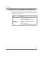
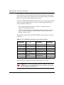
Finding the most recent updates on the Nortel Web site
The content of this documentation is current at the time the product is released. To
check for updates to the most recent documentation and software for VPN Router
1750, click one of the following links.
Link
Web site
Most recent software
Nortel page for VPN Router software located at
support.nortel.com/go/
main.jsp?cscat=SOFTWARE&poid=12325
Most recent
documentation
Nortel page for VPN Router documentation
located at
support.nortel.com/go/
main.jsp?cscat=DOCUMENTATION&poid=12325
NN46110-316 03.01
Preface
17
Getting help from the Nortel Web site
The best way to get technical support for Nortel products is from the Nortel
Technical Support Web site:
www.nortel.com/support
This site provides quick access to software, documentation, bulletins, and tools to
address issues with Nortel products. From this site, you can perform the following
activities:
•
•
•
•
download software, documentation, and product bulletins
search the Technical Support Web site and the Nortel Knowledge Base for
answers to technical issues
sign up for automatic notification of new software and documentation for
Nortel equipment
open and manage technical support cases
Getting help over the phone from a Nortel Solutions Center
If you do not find the information you require on the Nortel Technical Support
Web site, and you have a Nortel support contract, you can also get help over the
phone from a Nortel Solutions Center.
In North America, call 1-800-4NORTEL (1-800-466-7835).
Outside North America, go to the following Web site to obtain the phone number
for your region:
www.nortel.com/callus
Getting help from a specialist by using an Express Routing
Code
To access some Nortel Technical Solutions Centers, you can use an Express
Routing Code (ERC) to quickly route your call to a specialist in your Nortel
product or service. To locate the ERC for your product or service, go to the
following Web site:
Nortel VPN Router Installation — VPN Router 1750
18
Preface
www.nortel.com/erc
Getting help through a Nortel distributor or reseller
If you purchased a service contract for your Nortel product from a distributor or
authorized reseller, contact the technical support staff for that distributor or
reseller.
NN46110-316 03.01
19
New in this release
The following section details what’s new in Nortel VPN Router Installation—
VPN Router 1750 (NN46110-316) for Release 8.0:
•
•
“Features” on page 19
“Other changes” on page 19
Features
See the following section for information about feature changes:
•
“Models” on page 19
Models
Starting with Release 8.0, the Nortel VPN Router 1750 is available in two 128-bit
models. For more information, see “Description of the Nortel VPN Router 1750”
on page 37.
Other changes
For information that is not feature related, see the following section:
•
“Document changes” on page 19
Document changes
This document is changed to comply with Nortel writing conventions.
Nortel VPN Router Installation — VPN Router 1750
20
New in this release
NN46110-316 03.01
21
Chapter 1
Cables and power
This chapter provides information about how to connect communications cables
and the power cord to the VPN Router 1750.
Caution: Before you plug the power cord into the outlet, connect the
cables to the built-in Ethernet ports and to the interfaces on the option
cards installed in the VPN Router 1750.
This chapter contains the following topics:
•
•
•
•
“Connecting communications cables” on page 22
“Connecting the power cord” on page 24
“Verifying a successful installation” on page 25
“LEDs” on page 26
Caution: You must route the cabling for all wide area network (WAN),
local area network (LAN), and serial connections inside the building
environment.
Nortel VPN Router Installation — VPN Router 1750
22 Chapter 1 Cables and power
Connecting communications cables
Gather the cables to attach to the VPN Router 1750.
“Interfaces and cables for the Nortel VPN Router 1750” on page 22 lists the
system ports and the ports on the optional interface cards that you can install in the
VPN Router 1750. The following table also indicates whether you can obtain
cables for the ports from Nortel.
Table 1 Interfaces and cables for the Nortel VPN Router 1750
Cable available from Nortel
Interface
Included
Ordered separately
10/100BASE-TX Ethernet system ports
Serial port
Contact supplier
X
X
10/100BASE-TX Ethernet
X
1000BASE-T (1000 GT) Ethernet
X
1000BASE-T (1000 MT) Ethernet
(copper)
X
1000BASE-SX Ethernet (fiber)
Order either the LC-to-LC
cable or the LC-to-SC
cable.
56/64K Channel Service Unit (CSU)/
Data Service Unit (DSU) WAN
Asymmetric Digital Subscriber Line
(ADSL) WAN
X
X
Integrated Services Digital Network
(ISDN) Basic Rate Interface (BRI)
V.90 modem
X
X
T1/E1 CSU/DSU WAN
X
Quad T1/E1 CSU/DSU WAN
X
Single V.35/X.21 WAN
Order either the V.35
cable or the X.21 cable.
Dual V.35 WAN
X
HSSI WAN
X
NN46110-316 03.01
Chapter 1 Cables and power 23
For information about the connectors and cable pinouts, see Appendix A,
“Technical specifications,” on page 69.
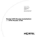
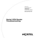
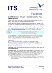
“Rear view of the Nortel VPN Router 1750” on page 23 shows the back of the
VPN Router 1750. All interface cables and the power cord attach to the rear of the
gateway.
Figure 1 Rear view of the Nortel VPN Router 1750
4 PCI slots
VPN Router 1750
100 - 240 V~
5-3A
60 - 50 Hz
LAN0
LAN1
Power
Serial Port
1
AC
Power
receptacle switch
Serial port
2
3
4
10/100
Ethernet
LAN ports
11424EA
Connect the interface cables to the VPN Router 1750 in the following order:
1
Connect the 10/100BASE-TX RJ-45 cables to the built-in 10/100BASE-TX
Ethernet LAN ports on the gateway.
2
If you plan to connect a terminal or PC to the gateway, connect the serial cable
that ships with the VPN Router 1750 to the serial port.
3
Connect all other cables to the ports on the installed interface cards.
If you ordered optional interface cards, connect the cables for these interfaces
to the ports.
Nortel VPN Router Installation — VPN Router 1750
24 Chapter 1 Cables and power
Connecting the power cord
You must order the power cord for the VPN Router 1750 separately.
Caution: Risk of equipment damage
Do not modify or use the AC power cord if it is not the exact type that is
required for your power outlet.
The power cord must meet the requirements described in “Power cord
requirements” on page 24.
Table 2 Power cord requirements
Requirement
Description
Current rating
The power cord must be rated for the available AC voltage and
must have a current rating that is at least 125 percent of the
current rating of the gateway (5 A @ 100 Voltage Alternating
Current (VAC) or 3 A @ 240 VAC).
Certification
The power cord must have certification marks from an
acceptable regional agency.
Cord length and flexibility The power cord must be less than 4.5 meters (14.7 feet) long.
The cord must be a flexible harmonized cord or VDE-certified
cordage to comply with the gateway safety certifications.
Power supply connector
The connector that you plug into the AC receptacle on the
gateway must be an IEC 320, Sheet C13 female.
Wall outlet connector
The power cord must terminate in a male plug with
appropriate grounding.
To connect the power cord and turn on the system power, perform the following
steps:
1
Connect the power cord to the AC receptacle on the back of the gateway, as
shown in “Rear view of the Nortel VPN Router 1750” on page 23.
2
Connect the power cord to the power outlet.
Caution: Risk of equipment damage
Protect the VPN Router 1750 by plugging it into a surge suppressor.
NN46110-316 03.01
Chapter 1 Cables and power 25
3
Press and release the power switch on the rear of the VPN Router 1750, and
wait for the gateway to start.
Verifying a successful installation
After you connect the gateway to the power source and turn it on, you can verify a
successful installation by checking the light emitting diodes (LED) on the front
panel. For more information, see “Front panel LEDs” on page 26.
The following sequence of LEDs occurs:
1
The power LED (the Nortel logo) lights blue.
2
The Alert LED lights red and the Boot/Ready LED lights green.
3
When the gateway begins the boot sequence, the Boot/Ready LED lights
yellow and the Alert LED turns off.
4
After the boot process is complete, the Boot/Ready LED lights green, which
indicates that the gateway is operational.
5
The Alert LED lights yellow because the gateway is not configured.
For a newly installed VPN Router 1750, a yellow Alert LED does not indicate
an alarm condition. After you configure the gateway, the Alert LED turns off.
For more information, see Chapter 4, “Management IP interface
configuration,” on page 61.
If the LEDs on the front panel light in the preceding sequence, the installation is
successful. If the LEDs do not light in the preceding sequence, check that you
correctly installed the bezel on the gateway and that you properly attached the
power cord to the power supply. For more information, see “Connecting the power
cord” on page 24.
If the VPN Router 1750 still does not start, contact your local Nortel Technical
Solutions Center. For more information, see “How to get help” on page 15.
Nortel VPN Router Installation — VPN Router 1750
26 Chapter 1 Cables and power
LEDs
This section describes the LEDs on the front panel of the VPN Router 1750 and
on the interface cards that use LEDs. You can confirm that you properly connect
the LAN and WAN interface cables by examining the LEDs.
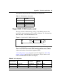
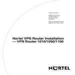
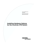
Front panel LEDs
The front panel of the VPN Router 1750 has a lighted Nortel logo and two LEDs
as shown in the following figure. These LEDs indicate the status of the VPN
Router 1750.
Figure 2 Front panel LEDs
Power
Alert
Alert
Boot/Ready
Boot/Ready
CS160013A
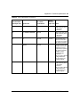
The following table describes the LEDs on the VPN Router 1750 front panel.
Table 3 Front panel LED indicators
LED
Indicator
Description
Power (Nortel
logo)
On
The gateway receives AC power.
Off
The gateway does not receive AC power.
Alert
Yellow
A nonfatal alarm condition exists. The health check
display describes the yellow alert condition.
Red
A serious alarm condition exists that requires attention.
A red alert usually indicates a hardware error. The health
check display describes the red alert condition.
Yellow
The gateway is starting and is in a nonready state.
Green
The boot process is complete, and the gateway is in a
state of readiness.
Boot/Ready
For more information about the health check, event log, and system log, see
Nortel VPN Router Troubleshooting — Server (NN46110-602).
NN46110-316 03.01
Chapter 1 Cables and power 27
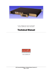
LEDs on the system 10/100BASE-TX Ethernet ports
Each of the 10/100BASE-TX Ethernet ports on the rear of the VPN Router 1750
has two LEDs; see “LEDs on the system 10/100BASE-TX Ethernet ports” on
page 27.
Figure 3 LEDs on the system 10/100BASE-TX Ethernet ports
Yellow
Green
CS260011A
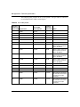
The following table describes the LEDs on the system 10/100BASE-TX Ethernet
ports.
Table 4 LED indicators on the system 10/100BASE-TX Ethernet ports
LED
Indicator
Description
Green
On
The LAN port operates at 100 Megabits per second
(Mb/s).
Off
The LAN port operates at 10 Mb/s.
On
The cable connections between the LAN port and the
hub are good.
Off
The cable connections between the LAN port and the
hub are faulty.
Flashing
The LAN port is sending or receiving network data.
The frequency of the flashes increases with
increased traffic.
Yellow
Nortel VPN Router Installation — VPN Router 1750
28 Chapter 1 Cables and power
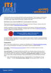
10/100BASE-TX Ethernet interface card LEDs
The following figure shows the LEDs on the 10/100BASE-TX Ethernet interface
card.
Activity/Link
100TX
ACT/LINK
DATA
Figure 4 LEDs on the 10/100BASE-TX Ethernet interface card
10/100 Mb/s
CS260009A
The following table describes the LEDs on the 10/100BASE-TX Ethernet
interface card.
Table 5 LED indicators on the 10/100BASE-TX Ethernet interface card
LED
Indicator
Description
ACT/LINK
Steady green or
flashing green
The card is sending or receiving network data. The
frequency of the flashes increases with increased
traffic.
Off
The card is not sending or receiving data.
Green
The port operates at 100 Mb/s.
Off
The port operates at 10 Mb/s.
10/100TX
1000BASE-T (1000 GT) Ethernet interface card LEDs
The following figure shows the LEDs on the 1000BASE-T (1000 GT) Ethernet
interface card.
Figure 5 LEDs on the 1000BASE-T (1000 GT) Ethernet interface card
NN46110-316 03.01
Chapter 1 Cables and power 29
The following table describes the LEDs on the 1000BASE-T (1000 GT) Ethernet
interface card.
Table 6 LED indicators on the 1000BASE-T (1000 GT) Ethernet interface card
LED
Indicator
Description
ACT/LINK
Steady green
The port connects to a valid link partner.
Flashing green
The card is sending or receiving network data. The
frequency of the flashes increases with increased
traffic.
Off
The card is not sending or receiving data.
Yellow
The port operates at 1000 Mb/s.
Green
The port operates at 100 Mb/s.
Off
The port operates at 10 Mb/s.
10/100/1000
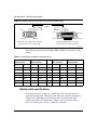
1000BASE-T (1000 MT) Ethernet interface card LEDs
The following figure shows the LEDs on the 1000BASE-T (1000 MT) Ethernet
interface card.
10 = OFF
100 = GRN
1000 = ORG
ACT/LNK
R
Intel PRO
Figure 6 LEDs on the 1000BASE-T (1000 MT) Ethernet interface card
ACT/LNK
10/100/1000
11287EA
The following table describes the LEDs on the 1000BASE-T Ethernet interface
card.
Table 7 LED indicators on the 1000BASE-T (1000 MT) Ethernet interface card
LED
Indicator
Description
ACT/LNK
Steady green
The port connects to a valid link partner.
Flashing green
The LAN port is sending or receiving network data.
Off
The port does not link to a valid partner.
Nortel VPN Router Installation — VPN Router 1750
30 Chapter 1 Cables and power
Table 7 LED indicators on the 1000BASE-T (1000 MT) Ethernet interface card
LED
Indicator
Description
10/100/1000
Off
The LAN port operates at 10 Mb/s.
Green
The LAN port operates at 100 Mb/s.
Orange
The LAN port operates at 1000 Mb/s.
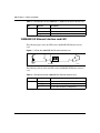
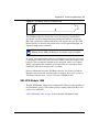
1000BASE-SX Ethernet interface card LED
The following figure shows the LED on the 1000BASE-SX Ethernet interface
card.
ACT/LNK
R
Intel PRO
Figure 7 LED on the 1000BASE-SX Ethernet interface card
ACT/LNK
11288EA
The following table describes the LED on the 1000BASE-SX Ethernet interface
card.
Table 8 LED indicator on the 1000BASE-SX Ethernet interface card
LED
Indicator
Description
ACT/LNK
Steady green
The port connects to a valid link partner.
Flashing green
The LAN port is sending or receiving network data.
Off
The port does not link to a valid partner.
NN46110-316 03.01
Chapter 1 Cables and power 31
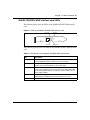
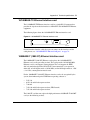
56/64K CSU/DSU WAN interface card LEDs
The following figure shows the LEDs on the 56/64K CSU/DSU WAN interface
card.
Figure 8 LEDs on the 56/64K CSU/DSU WAN interface card
Blue LED
Red LED
56/64K
DDS
Green LED
Yellow LED
The following figure describes the LEDs on the 56/64K CSU/DSU WAN interface
card.
Table 9 LED indicators on the 56/64K CSU/DSU WAN interface card
LED
Description
Blue
The blue alarm LED lights after the interface card detects a digital data
service (DDS) out-of-frame condition on the receive signal.
Red
The red alarm LED lights after the interface card detects a DDS loss-ofsignal or loss-of-frame condition on the receive signal.
Yellow
The yellow alarm LED lights after the interface card detects a DDS
out-of-service condition on the receive signal. This LED indicates that
the far-end equipment detects a local loss of service (LOS) or loss of
frame (LOF) condition.
Green
The green LED lights after the interface card receives valid DDS signal
and framing. This LED indicates normal operation of the card.
All LEDs off
The port is disabled.
Nortel VPN Router Installation — VPN Router 1750
32 Chapter 1 Cables and power
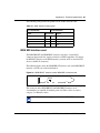
ADSL WAN interface card LEDs
The following figure shows the LEDs on the asymmetric digital subscriber line
(ADSL) WAN interface card.
Figure 9 LEDs on the ADSL WAN interface card
RX/TX LED
RX/TX
ADSL
CONN
CONN LED
The following table describes the LEDs on the ADSL WAN interface card.
Table 10 LED indicators on the ADSL WAN interface card
CONN LED
Tx/Rx LED
Description
Steady green
Steady green
The ADSL interface card is not initialized; the
software driver is not installed.
Off
Off
The ADSL interface card is initialized, but has not
established a link with the ADSL network.
Flashing green
Off
The ADSL interface card is attempting to establish a
link with the ADSL network.
Steady green
Off
The ADSL interface card has established a link with
the ADSL network.
Steady green
Flashing green
The ADSL interface card is sending or receiving
network data. The LED can appear dim.
NN46110-316 03.01
Chapter 1 Cables and power 33
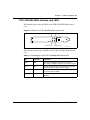
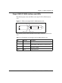
T1/E1 CSU/DSU WAN interface card LEDs
The following figure shows the LEDs on the T1/E1 CSU/DSU WAN interface
card.
Figure 10 LEDs on the T1/E1 CSU/DSU WAN interface card
LED 1, Red
LED 2, Blue
LED 4, Green
LED 3, Yellow
CS160012A
The following table describes the LEDs on the T1/E1 CSU/DSU WAN interface
card.
Table 11 LED indicators on the T1/E1 CSU/DSU WAN interface card
LED
Indicator
Description
LED 1
Red
The red alarm LED lights after a loss-of-signal or
out-of-frame condition is detected on the receive signal.
LED 2
Blue
The blue alarm LED lights after receiving an upstream
failure denoted by an alarm indication signal.
LED 3
Yellow
The yellow alarm LED lights when the far-end equipment
is in the red alarm condition.
LED 4
Green
The green LED lights when the condition is normal
operation.
Nortel VPN Router Installation — VPN Router 1750
34 Chapter 1 Cables and power
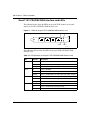
Quad T1/E1 CSU/DSU WAN interface card LEDs
The following figure shows the LEDs on the quad T1/E1 channel service unit/
digital service unit (CSU/DSU) WAN interface card.
Figure 11 LEDs on the quad T1/E1 CSU/DSU WAN interface card
LED 1
LED 2
LED 3
LED 4
CS160012A
The following table describes the LEDs on the quad T1/E1 CSU/DSU WAN
interface card.
Table 12 LED indicators on the quad T1/E1 CSU/DSU WAN interface card
LED
Indicator
Description
LED 1
Off
Port 1 is disabled.
On
Port 1 is enabled and operating normally.
Flashing
Port 1 is enabled and in an alarm state (red, yellow, or blue).
Off
Port 2 is disabled.
On
Port 2 is enabled and operating normally.
Flashing
Port 2 is enabled and in an alarm state (red, yellow, or blue).
Off
Port 3 is disabled.
On
Port 3 is enabled and operating normally.
Flashing
Port 3 is enabled and in an alarm state (red, yellow, or blue).
Off
Port 4 is disabled.
On
Port 4 is enabled and operating normally.
Flashing
Port 4 is enabled and in an alarm state (red, yellow, or blue).
LED 2
LED 3
LED 4
NN46110-316 03.01
Chapter 1 Cables and power 35
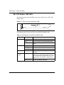
Single V.35/X.21 WAN interface card LEDs
The following figure shows the LEDs on the single V.35/X.21 WAN interface
card.
Figure 12 LEDs on the single V.35/X.21 WAN interface card
LED 1, Red
LED 2, Green
LED 4, Green
LED 3, Green
The following table describes the LEDs on the single V.35/X.21 WAN interface
card.
Table 13 LED indicators on the single V.35/X.21 WAN interface card
LED
Indicator
Description
LED 1
Red
No external transmit clock source is available.
LED 2
Green
The signals CDC and DSR are on between the DSU
and the adapter. LED 2 detects receive link status.
LED 3
Green
The power to the adapter is on and the onboard
microcode is loaded.
LED 4
Green
A cable is detected.
Nortel VPN Router Installation — VPN Router 1750
36 Chapter 1 Cables and power
SSL VPN Module 1000 LEDs
The following figure shows the LEDs on the Secure Sockets Layer (SSL) VPN
Module 1000.
Figure 13 LEDs on the SSL VPN Module 1000
Utilization
1
Online
2 - Activity
11356EA
The following table describes the LEDs on the SSL VPN Module 1000.
Table 14 LED indicators on the SSL VPN Module 1000
LEDs
Indicator
Description
Online
Steady green
The SSL VPN Module 1000 operates normally.
Yellow
A reset occurred on the SSL VPN Module 1000.
Off
The SSL VPN Module 1000 does not receive
power.
Steady green
The SSL VPN Module 1000 operates normally.
Flashing green
Activity occurs on the SSL VPN Module 1000.
Yellow
A reset occurred on the SSL VPN Module 1000.
Activity LED 1
Activity LED 2
Utilization
(4 LEDs)
NN46110-316 03.01
—
Not used. This LED often lights, but it has no
meaning.
Steady green
Together, these four LEDs indicate an approximate
average level of CPU utilization. When one LED
lights, CPU utilization is approximately 25%; when
two LEDs light, CPU utilization is approximately
50%.
Blinking in unison
The SSL VPN Module 1000 is idle.
37
Chapter 2
Nortel VPN Router 1750 chassis
This chapter describes how to install the VPN Router 1750 chassis.
Note: Before you install the chassis, use standard cable system practices
to install all network wiring on the premises.
This chapter contains the following topics
•
•
•
“Description of the Nortel VPN Router 1750” on page 37
“Preparation” on page 38
“Chassis installation” on page 41
Description of the Nortel VPN Router 1750
With the VPN Router 1750, you can supply scalable, secure, and robust Internet
Protocol (IP) virtual private networks (VPN) across the public data network. The
VPN Router 1750 provides routing, firewall, bandwidth management, encryption,
authentication, and data integrity services to ensure secure tunneling across IP
networks and the Internet.
The VPN Router 1750 is available in the following two models:
•
•
VPN Router 1750 with 50 tunnels (128-bit)
VPN Router 1750 with 500 tunnels (128-bit)
Nortel VPN Router Installation — VPN Router 1750
38 Chapter 2 Nortel VPN Router 1750 chassis
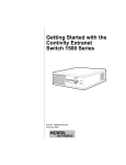
The following figure shows the front view of the Nortel VPN Router 1750.
Figure 14 Front view of the Nortel VPN Router 1750
Alert
Boot/Ready
CS260001D
The VPN Router 1750 chassis provides the following physical features:
•
•
•
•
two 10/100 Ethernet local area network (LAN) ports on the base system
one serial port for out-of-band management of the VPN Router 1750
four expansion peripheral component interconnect (PCI) slots that can contain
interface cards, a VPN Accelerator card (VPN Router Security Accelerator
[CSA] card or Hardware Accelerator card), and the Secure Sockets Layer
(SSL) VPN Module 1000
a memory of 128 Megabytes (MB) that you can upgrade to 256 MB
Preparation
Before you begin the installation, verify the following items:
•
•
•
The shipment is complete and undamaged.
You have the cables, tools, and other equipment that you need.
Your installation site meets the physical, electrical, and environmental
requirements.
The following sections provide information to help you prepare for installation.
NN46110-316 03.01
Chapter 2 Nortel VPN Router 1750 chassis 39
Shipment contents
In addition to the gateway and this guide, the shipping container for the VPN
Router 1750 contains a number of hardware accessories and other items.
Note: Unless you specifically ordered a power cable, Nortel does not
ship one with the VPN Router 1750.
Table 15 Items shipped with the Nortel VPN Router 1750
Quantity
Item
Purpose
1
Rack mount shelf
Supports the chassis in the equipment rack
4
10-32 panhead screws
Secures the rack-mount shelf and the chassis to
the equipment rack
4
10-32 panhead cage nuts
Secures the rack-mount shelf and the chassis if
the equipment rack does not have threaded rail
holes
4
Rubber feet
Installs the chassis on a surface
1
Antistatic wrist strap
Directs the discharge of static electricity from
your body to the chassis to prevent damage to
sensitive electronic components
1
Molded serial cable
DB9/DB25-to-DB9/DB25
Connects the VPN Router 1750 to a PC or to a
local terminal
1
Nortel VPN Router
Installation — VPN Router
1750 (NN46110-316) (this
book)
Provides instructions to install the chassis and
hardware options
1
Recovery diskette
Restores the software image and file system
1
VPN Router software kit
Contains Nortel VPN Router 1750 software and
documentation on a CD
1
VPN client kit
Contains Nortel VPN Client software and
documentation on a CD
1
Sheet of labels
Records the IP address (apply to front bezel)
Inspect all items for shipping damage. If you detect damage, do not install the
VPN Router 1750. Call the Nortel Technical Solutions Center in your area.
Nortel VPN Router Installation — VPN Router 1750
40 Chapter 2 Nortel VPN Router 1750 chassis
Additional equipment
You need items that do not ship in the VPN Router 1750 shipping container.
Before you begin the installation, ensure that you have all the cables, tools, and
other equipment that you need.
Cables
You need cables that do not ship in the VPN Router 1750 shipping container. For
more information about which cables ship and which ones you can order, see
“Connecting communications cables” on page 22. If you do not have the proper
cables, contact your network administrator.
Hardware to mount the chassis in an equipment rack
To install the VPN Router 1750 in an equipment rack, you need a Phillips
screwdriver and an equipment rack that meets the following specifications:
•
•
•
heavy-duty steel construction
width of 19 in. (48.26 cm) and depth of 24 in. (60.96 cm)
Electronic Industries Association (EIA) standard hole-spacing
If the rack does not have threaded rail holes, you must use the cage nuts that ship
with the VPN Router 1750.
Site requirements
The installation site must provide sufficient free space around the VPN Router
1750 to ensure proper ventilation and service access. For information about the
physical, electrical, and environmental requirements for the VPN Router 1750,
see Appendix A, “Technical specifications,” on page 69.
NN46110-316 03.01
Chapter 2 Nortel VPN Router 1750 chassis 41
Chassis installation
To install the VPN Router 1750, perform one of the following procedures:
•
•
Position the chassis on a flat, sturdy, horizontal surface.
Mount the chassis in a standard equipment rack. For more information, see
“Installing the chassis in an equipment rack” on page 42.
Installing the chassis on a flat surface
If you decide to place the VPN Router 1750 on a flat surface, make sure that the
surface is large enough for the gateway, and sturdy enough to support the
combined weight of the VPN Router 1750 and the cables that you attach to it.
The VPN Router 1750 accessory kit includes four rubber feet that you can attach
to the bottom of the gateway. The following figure shows the placement of the
rubber feet.
Figure 15 Placement of rubber feet on the bottom of the chassis
Attach feet (4)
CS160016A
Nortel VPN Router Installation — VPN Router 1750
42 Chapter 2 Nortel VPN Router 1750 chassis
Installing the chassis in an equipment rack
To mount the VPN Router 1750 in an equipment rack, you need the following
equipment:
•
•
•
•
standard 19-inch equipment rack
four screws (supplied with the chassis)
four cage nuts (supplied with the chassis) if the rack does not have threaded
rail holes
a #2 Phillips screwdriver
Rack-mount recommendations
When you mount the chassis in the equipment rack, observe the following
standard recommendations:
•
•
•
•
•
The maximum recommended ambient temperature is 40oC (104oF). Ensure
that the internal temperature of the rack does not exceed 40oC (104oF).
Do not block the power supply vents or otherwise restrict air flow when you
install the chassis in the rack.
Stabilize the rack so that it does not tip over under the weight of the gateway
and other devices.
Before you install and turn on the gateway, ensure that the electrical branch
circuits can handle the VPN Router 1750 and other units in the rack.
Maintain a reliable earth-ground path in the rack system. You must connect
the gateway to an earth ground.
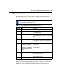
Attaching the shelf in the equipment rack
The VPN Router 1750 ships with a rack-mount shelf to support the chassis in the
equipment rack.
To attach the shelf to the inside of the equipment rack, perform the following
steps:
NN46110-316 03.01
Chapter 2 Nortel VPN Router 1750 chassis 43
1
Attach a cage nut in four locations at the front of the rack, if the holes in the
vertical supports of the rack are not threaded.
Rail
without
threaded
holes
Cage nut
CS260003A
2
Position the rack-mount shelf inside the rack as shown in the following
graphic.
Rack edge
Flange
CS260003A
3
Align the holes in the shelf with holes in the front of the rack.
4
Snap the support flange into place. Ensure that the alignment pin above the
flange fits into the appropriate hole.
5
Insert one of the supplied panhead screws through the top hole on each side of
the shelf into the hole in the rack, and tighten the screws.
Nortel VPN Router Installation — VPN Router 1750
44 Chapter 2 Nortel VPN Router 1750 chassis
Mounting the chassis in the equipment rack
Nortel recommends that two people install the chassis in the rack.
To install the VPN Router 1750 in the equipment rack, perform the following
steps:
1
Set the VPN Router 1750 on the rack-mount shelf.
2
Remove the front bezel from the VPN Router 1750 as shown in the following
figure.
CS260015E
3
Use the Phillips screwdriver to turn each of the two screws on the front bezel a
quarter turn counterclockwise.
4
Grip the two handles, and firmly pull the bezel toward you to unsnap it from
the chassis.
Caution: Risk of equipment damage
Do not use the piece with the Nortel logo and the LEDs as a handle.
The first several times that you remove the front bezel, the bezel can stick
because the ball studs and socket clips are new.
5
NN46110-316 03.01
Insert one of the supplied panhead screws through the bottom hole on each
side of the shelf into the hole in the rack, and tighten the screws.
Chapter 2 Nortel VPN Router 1750 chassis 45
6
Replace the front bezel as shown in the following figure.
Press here
CS260005E
7
Hold the two handles on the bezel, and push it onto the chassis.
8
Use the Phillips screwdriver to tighten the two screws that secure the bezel to
the chassis.
Nortel VPN Router Installation — VPN Router 1750
46 Chapter 2 Nortel VPN Router 1750 chassis
NN46110-316 03.01
47
Chapter 3
Option card and DIMM installation
This chapter provides instructions about how to install and replace the following
field replaceable units (FRU) in the VPN Router 1750:
•
•
•
•
Local Area Network (LAN), Wide Area Network (WAN), and serial interface
cards
Secure Sockets Layer (SSL) VPN Module 1000
VPN Accelerator cards (VPN Router Security Accelerator [CSA] card and
Hardware Accelerator card)
dual inline memory modules (DIMM)
This chapter contains the following topics:
•
•
•
•
•
“Shutting down the system to add or replace hardware” on page 48
“Removing the front bezel and top cover” on page 49
“Attaching the antistatic wrist strap” on page 52
“Option card installation and replacement” on page 53
“Installing and replacing DIMMs” on page 57
Nortel VPN Router Installation — VPN Router 1750
48 Chapter 3 Option card and DIMM installation
Shutting down the system to add or replace hardware
To install or replace an option card or a DIMM, you must first shut down the VPN
Router 1750 and unplug it.
Warning: Risk of electric shock
Before you attempt to add or replace an option card or DIMM, shut
down the VPN Router 1750 as described in this section.
To shut down the VPN Router 1750, perform the following steps:
1
Use the Web graphical user interface (GUI) or the command line interface
(CLI) to shut down the gateway.
•
Web GUI: Choose Admin, Shutdown. Select the option to turn off the
gateway after shutdown.
OR
•
CLI: Use the reload command to shut down the system. For example,
enter reload power-off disable-logins “Upgrade hardware”
For more information about the reload command, see Nortel VPN
Router Using the Command Line Interface (NN46110-507).
2
Wait for the system to shut down.
3
Disconnect the power cord from the power outlet, and then disconnect the
power cord from the VPN Router 1750.
The power receptacle is on the rear of the VPN Router 1750 (see “Rear view
of the Nortel VPN Router 1750” on page 23).
Warning: Risk of electric shock
Make sure to turn off the VPN Router 1750 and unplug the power cord
before you attempt to remove or install an option card or DIMM.
NN46110-316 03.01
Chapter 3 Option card and DIMM installation 49
Removing the front bezel and top cover
To install option cards or DIMMs, you must remove the front bezel and the top
cover from the gateway.
To remove the front bezel, perform the following steps:
1
Shut down the VPN Router 1750 using the Web GUI or the CLI, and then
unplug it as described in “Shutting down the system to add or replace
hardware” on page 48.
Warning: Risk of electric shock
Make sure to turn off the VPN Router 1750 and unplug it before you
attempt to install an option card or DIMM.
2
Use a Phillips screwdriver to turn each of the two screws on the front bezel a
quarter turn counterclockwise as shown in the following figure.
CS260015E
3
Grip the two handles, and firmly pull the bezel toward you to unsnap it from
the chassis.
Caution: Risk of equipment damage
Do not use the piece with the Nortel logo and the LEDs as a handle.
Nortel VPN Router Installation — VPN Router 1750
50 Chapter 3 Option card and DIMM installation
The first several times that you remove the front bezel, the bezel can stick
because the ball studs and socket clips are new.
To remove the top cover, perform the following steps:
1
Remove the router from the rack if it is mounted in an equipment rack.
2
At the front of the chassis, remove the two panhead screws that secure the
bottom of the chassis to the equipment rack.
3
Remove the VPN Router 1750 from the rack-mount shelf, and then set the
router on a sturdy surface.
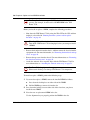
4
Use a Phillips screwdriver to remove the four screws that secure the cover to
the chassis as shown in the following figure.
Remove these 4 screws
Alert
Boot/Ready
Alert
Boot/Ready
Slide cover forward and lift up
CS260006A
5
NN46110-316 03.01
Slide the top cover forward approximately 1/4 inch.
Chapter 3 Option card and DIMM installation 51
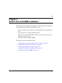
6
Lift the lid 2 or 3 inches, and then pull it off the chassis.
The VPN Router 1750 system board is now exposed. The following figure
shows the location of the option card and DIMM slots on the system board.
DIMMs (1 and 2)
Option card slots
2
1
DIMM
slots
1
2
3
4
PCI
slots
CS160004A
Warning: Risk of injury
Beware of danger if you incorrectly replace the battery. Replace the
battery with the same type or an equivalent battery only as recommended
by the instructions from the manufacturer. In spite of this warning, which
is mandated for regulatory approval, you must not change the battery. If
you suspect that the battery is dead, contact Global Nortel Technical
Support (GNTS).
Nortel VPN Router Installation — VPN Router 1750
52 Chapter 3 Option card and DIMM installation
Attaching the antistatic wrist strap
Nortel ships the VPN Router 1750 with an antistatic wrist strap, which directs the
discharge of static electricity from your body to the chassis of the gateway to
avoid damage to sensitive electronic components.
You must wear an antistatic wrist strap on your arm when you remove, install, or
handle option cards and DIMMs.
Caution: Risk of equipment damage
Electrostatic discharge can damage hardware. Perform the procedure in
this section to protect your equipment from damage.
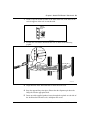
To attach the antistatic wrist strap, perform the following steps:
1
Locate the antistatic wrist strap, and then verify that the cable is attached to it.
2
Place the strap around your wrist, and then adjust the strap to ensure that the
metal buckle inside the strap touches your skin.
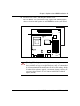
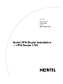
3
Insert the banana plug into the grounding jack at the rear of the chassis as
shown in the following figure.
Figure 16 Location of the grounding jack for the antistatic wrist strap
Grounding jack
VPN Router 1750
100 - 240 V~
5-3A
60 - 50 Hz
LAN0
LAN1
Power
Serial Port
1
2
3
4
11424EA
NN46110-316 03.01
Chapter 3 Option card and DIMM installation 53
Option card installation and replacement
The VPN Router 1750 provides four slots for option cards. This section provides
instructions about how you can add new option cards to the VPN Router 1750 or,
if necessary, replace an existing card.
The following table lists the option cards that you can install in the VPN Router
1750.
Table 16 Supported option cards for the Nortel VPN Router 1750
Option card
SSL VPN Module 1000
Maximum
number
1
VPN Router 1750 Security Accelerator
Restrictions
Install this card in slot 1 only. The VPN Router 1750
must run Version 5.0 or later.
Hardware Accelerator
1
Install one VPN Router 1750 Security Accelerator
card or one Hardware Accelerator card. Do not
install a Hardware Accelerator card in slot 4. The
VPN Router 1750 must run Version 4.90 or later.
10/100BASE-TX Ethernet interface
4
—
1000BASE-T (1000 GT) Ethernet
interface
4
The VPN Router 1750 must run Version 5.05.330,
6.05.140 and later, 7.00.062, 7.05.100 and later, or
7.05.300 and later.
1000BASE-T (1000 MT) interface
(copper)
1000BASE-SX interface (fiber)
2
Install two 1000BASE-T (1000 MT) cards, two
1000BASE-SX cards, or one card of each type. For
more information, see “Installing the SSL VPN
Module 1000 with other option cards” on page 54.
The VPN Router 1750 must run Version 4.90 or
later.
56/64K channel service unit/digital
service unit (CSU/DSU) WAN interface
4
The VPN Router 1750 must run Version 5.0 or later.
ADSL WAN interface
4
The VPN Router 1750 must run Version 4.90 or
later.
Integrated Services Digital Network
(ISDN) BRI S/T or U interface
4
The VPN Router 1750 must run Version 4.80 or
later.
T1CSU/DSU WAN interface (full-height)
4
T1/E1 CSU/DSU WAN interface
(half-height)
4
Quad T1/E1 CSU/DSU WAN interface
3
For E1 support, you must install the half-height
interface card.
The VPN Router 1750 must run Version 4.90 or
later.
Nortel VPN Router Installation — VPN Router 1750
54 Chapter 3 Option card and DIMM installation
Table 16 Supported option cards for the Nortel VPN Router 1750
Maximum
number
Option card
Restrictions
V.90 modem interface
4
If you install an SSL VPN Module 1000 in slot 1, do
not install the V.90 modem interface card in slot 2.
The VPN Router 1750 must run Version 4.80 or
later.
Single V.35/X.21 WAN interface
(full-height)
4
—
Single V.35/X.21 WAN interface
(half-height)
4
The VPN Router 1750 must run Version 4.80 or
later.
HSSI WAN interface
2
Do not install in slot 4; install in slot 3 or 1 if possible.
If you install an SSL VPN Module 1000, you can
install only one HSSI WAN interface card.The
gateway must run Version 4.76 or later, or the
hardware revision must be at least 03.
Installing the SSL VPN Module 1000 with other option cards
If you install an SSL VPN Module 1000 in the VPN Router 1750, the following
restrictions on other option cards apply:
•
•
•
You cannot install a V.90 modem interface card in slot 2.
You can install only one HSSI WAN interface card. Do not install this card in
slot 4; if possible, install it in slot 3.
You can install two 1000BASE-T/1000BASE-SX interface cards only if you
do not install one of the following option cards:
— VPN Router Security Accelerator
— Hardware Accelerator
— HSSI WAN interface
If you install a VPN Router Security Accelerator, Hardware Accelerator, or
HSSI WAN interface card, you can install only one 1000BASE-T or
1000BASE-SX interface card.
NN46110-316 03.01
Chapter 3 Option card and DIMM installation 55
Installing and replacing an option card
Before you install or replace an interface card or Hardware Accelerator card,
complete the following procedures:
•
Shut down the VPN Router 1750 by using the Web GUI or the CLI, and then
unplug it as described in “Shutting down the system to add or replace
hardware” on page 48.
Warning: Risk of electric shock
Turn off the VPN Router 1750 and unplug it before you attempt to install
an option card.
•
•
•
Remove the front bezel from the chassis, and then remove the chassis from the
equipment rack. For more information, see “Removing the front bezel and top
cover” on page 49.
Remove the top cover from the chassis. For more information, see “Removing
the front bezel and top cover” on page 49.
Attach the antistatic wrist strap that ships with the VPN Router 1750. For
more information, see “Attaching the antistatic wrist strap” on page 52.
To install or replace an interface card or a Hardware Accelerator card:
1
Locate the slot where you plan to install the new or replacement option card.
Note: Do not try to install an HSSI WAN interface card or a Hardware
Accelerator card in slot 4.
Nortel VPN Router Installation — VPN Router 1750
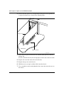
56 Chapter 3 Option card and DIMM installation
2
Remove the filler panel screw, and pull out the filler panel (or the option card
to replace) from the slot as shown in the following figure.
Rear of unit
Filler panel screw
Option card
Motherboard
Option card slots
CS2600017A
3
Lower the new option card into the slot, and then gently press the connector
into the slot.
Seat the card in the slot. If you do not properly seat the card, it does not work.
4
Replace the screw that secures the card to the slot.
5
Replace the top cover on the chassis.
6
Hold the cover at an angle, and then slide it onto the chassis.
7
Use a screwdriver to insert and tighten the four screws that secure the cover to
the chassis.
NN46110-316 03.01
Chapter 3 Option card and DIMM installation 57
8
If you want to install the VPN Router 1750 in an equipment rack, mount it in
the rack.
9
Set the VPN Router 1750 on the rack-mount shelf in the rack.
10 Insert one of the panhead screws through the bottom hole on each side of the
shelf into the hole in the rack, and tighten the screws.
11 Replace the front bezel.
12 Hold the bezel by the two handles, and push it onto the chassis.
13 Use a screwdriver to tighten the two screws that secure the bezel to the
chassis; see the following figure.
Press here
CS260005E
Installing and replacing DIMMs
The VPN Router 1750 has two slots for DIMMs. Unless you order additional
memory, Nortel ships the VPN Router 1750 with one 128 Megabit (MB) DIMM
installed. You can install a second 128 MB DIMM to upgrade memory in the
gateway.
Caution: If you use a memory module not purchased from Nortel, you
can render your warranty or your service contract void.
Nortel VPN Router Installation — VPN Router 1750
58 Chapter 3 Option card and DIMM installation
Caution: Install the same type of DIMM that is installed in your
gateway. For example, do not install a 256 MB DIMM in the VPN
Router 1750.
Before you install or replace a DIMM, complete the following procedures:
•
Shut down the VPN Router 1750 by using the Web GUI or the CLI, and then
unplug it as described in “Shutting down the system to add or replace
hardware” on page 48.
Warning: Risk of electric shock
Turn off the VPN Router 1750 and unplug it before you attempt to install
a DIMM.
•
•
•
Remove the front bezel from the chassis, and then remove the chassis from the
equipment rack. For more information, see “Removing the front bezel and top
cover” on page 49.
Remove the top cover from the chassis. For more information, see “Removing
the front bezel and top cover” on page 49.
Attach the antistatic wrist strap that ships with the VPN Router 1750. For
more information, see “Attaching the antistatic wrist strap” on page 52.
Caution: Risk of equipment damage
Electrostatic discharge can damage VPN Router 1750 components.
To install or replace a DIMM, perform the following steps:
1
If you need to replace a DIMM, remove the installed DIMM as follows:
a
Press down the locking lever on either side of the DIMM.
b
Pull the DIMM up to remove it from the slot.
2
Press down the locking lever on either side of the slot where you plan to
install the new DIMM.
3
Place the new or replacement DIMM in the slot.
Use the alignment keys to properly position the DIMM in the slot.
NN46110-316 03.01
Chapter 3 Option card and DIMM installation 59
4
Press the DIMM firmly into the socket.
5
Pull up the locking lever on either side of the DIMM to snap it into position;
see the following figure.
Alignment keys
To remove DIMMs, pull back
locking levers and pull out DIMM.
To install DIMMs, pull back locking
levers and push in DIMM.
Locking lever
CS260019A
Nortel VPN Router Installation — VPN Router 1750
60 Chapter 3 Option card and DIMM installation
6
Replace the top cover on the chassis.
7
Hold the cover at an angle, and slide it onto the chassis.
8
Insert the four screws that secure the cover to the chassis, and use a
screwdriver to tighten the screws.
9
If you want to install the VPN Router 1750 in an equipment rack, mount it in
the rack.
10 Set the VPN Router 1750 on the rack-mount shelf in the rack.
11 Insert one of the panhead screws through the bottom hole on each side of the
shelf into the hole in the rack, and tighten the screws.
12 Replace the front bezel.
13 Hold the bezel by the two handles, and push it onto the chassis.
14 Use the screwdriver to tighten the two screws that secure the bezel to the
chassis.
NN46110-316 03.01
61
Chapter 4
Management IP interface configuration
This chapter describes how to configure a management Internet Protocol (IP)
address, subnet mask, and default gateway address on a newly installed VPN
Router 1750. After you complete the procedures in this chapter, you can configure
and manage the VPN Router 1750 by using a Web browser from a PC.
To configure the management IP interface, you can use the serial interface
configuration menu. You must connect a PC or terminal to the serial port on the
VPN Router 1750.
This chapter contains the following topics:
•
•
•
•
“Required information” on page 62
“Configuring the management IP address” on page 63
“Testing the configuration” on page 67
“Troubleshooting” on page 68
Nortel VPN Router Installation — VPN Router 1750
62 Chapter 4 Management IP interface configuration
Required information
Before you configure the management interface, collect the following
information:
•
IP address for the management interface
The management IP address must be accessible from one of the private
physical interfaces on the VPN Router 1750. For example, if you plan to
assign IP address 10.2.3.3 with subnet mask 255.255.0.0 to the private
physical interface, the management IP address must reside in the 10.2
network.
•
subnet mask
The subnet mask specifies which IP addresses are directly reachable on the
network and which ones must be routed through a gateway. For example, the
IP address 10.2.3.3 with a subnet mask of 255.255.0.0 indicates that all hosts
with addresses 10.2.n.n are directly reachable.
•
default gateway (optional)
The default gateway routes packets to destinations for which no specific route
exists in the routing table. You can configure a default gateway when you
assign the management IP address, or you can configure it at a later time.
Note: Write down and save the management IP address. You need the IP
address to configure the VPN Router 1750.
NN46110-316 03.01
Chapter 4 Management IP interface configuration 63
Configuring the management IP address
Use the serial interface to assign the VPN Router 1750 a management IP address
and subnet mask so that you can then use a Web browser for management.
To configure the management IP address using the serial interface, perform the
following steps:
1
Turn on the terminal or PC.
2
Configure the terminal or PC with the following specifications:
•
•
•
•
•
9600 baud
eight data bits
one stop bit
no parity
no flow control
3
Connect the serial cable (supplied with the VPN Router 1750) from the serial
port on the gateway to a terminal or to the communications port on a PC.
4
On the PC, start HyperTerminal or another terminal emulation program, and
press Enter.
The Nortel VPN Router window appears with the following message:
Nortel VPN Router
Copyright (c) 1999-2005 Nortel Networks, Inc.
Version:
Creation date:
Unit Serial Number:
V07_0.024
Jul 6 2006, 08:23:16
510649
Please enter the administrator's user name:
5
Enter the default user name and password for the administrator.
The factory default user name is admin, and the default password is setup. The
user name and password are case sensitive; see the following example.
Please enter the administrator's user name: admin
Please enter the administrator's password: *****
Nortel VPN Router Installation — VPN Router 1750
64 Chapter 4 Management IP interface configuration
The serial main menu appears with the following message.
Main Menu: System is currently in NORMAL mode.
0)
1)
2)
3)
4)
5)
6)
7)
8)
9)
B)
P)
C)
L)
R)
E)
Management Address
Interfaces
Administrator
Default Private Route Menu
Default Public Route Menu
Create A User Control Tunnel (IPsec) Profile
Restricted Management Mode
FALSE
Allow HTTP Management
TRUE
Firewall Options
Shutdown
System Boot Options
Configure Serial Port
Controlled Crash
Command Line Interface
Reset System to Factory Defaults
Exit, Save and Invoke Changes
Please select a menu choice (0 - 9,B,P,C,L,R,E):
6
To configure the Interface IP address from the serial menu, type 1, and then
press Enter.
The interface menu appears with the following message.
- Interface Menu
0) Slot 0, Port 2, Public LAN
IP Address =
Subnet Mask = 0.0.0.0
Speed/Duplex = AutoNegotiate
1) Slot 0, Port 1, Private LAN
IP Address =192.167.120.14
Subnet Mask = 255.255.255.0
Speed/Duplex = AutoNegotiate
R) Return to the Main Menu.
Please select a menu choice:
NN46110-316 03.01
Chapter 4 Management IP interface configuration 65
7
Type 0, and then press Enter to configure the IP address.
The IP address prompt appears:
0) Slot 0, Port 2, Public LAN
IP Address =
Subnet Mask = 0.0.0.0
Speed/Duplex = AutoNegotiate
*Type 0.0.0.0 to delete.
*Just type <CR> to skip.
Old IP address =
New IP address =
8
Type a new IP address, and then press Enter.
The subnet mask prompt appears:
Old Subnet Mask = 0.0.0.0
New Subnet Mask =
9
At the New Subnet Mask prompt, type the subnet mask for the management
IP address, and then press Enter.
The Speed/Duplex prompt appears.
10 Press Enter to leave the speed and duplex settings unchanged.
The Interface menu appears again with the changes you make:
0) Slot 0, Port 2, Public LAN
IP Address =
Subnet Mask = 0.0.0.0
Speed/Duplex = AutoNegotiate
1) Slot 0, Port 1, Private LAN
IP Address =192.167.120.14
Subnet Mask = 255.255.255.0
Speed/Duplex = AutoNegotiate
R) Return to the Main Menu.
Please select a menu choice:
Nortel VPN Router Installation — VPN Router 1750
66 Chapter 4 Management IP interface configuration
11 Type R, and then press Enter to return to the serial main menu.
12 To configure the management IP address, type 0, and then press Enter.
The Management IP Address menu appears:
- Management IP Address Menu
M) Management IP Address =
R) Return to the Main Menu
Please select a menu choice (M,R):
13 Type M, and then press Enter.
The Management IP Address prompt appears:
*Type 0.0.0.0 to delete.
*Just type <CR> to skip.
Old management IP address =
New management IP address =
14 Type the new management IP address, and then press Enter to configure the
management IP address.
The new IP management address appears in the Management IP Address
menu:
- Management IP address menu
M) Management IP Address =192.167.120.13
R) Return to the Main Menu
Please select a menu choice (M,R):
15 Type R, and then press Enter to return to the serial main menu.
The serial main menu appears.
16 From the serial main menu, type E, and then press Enter to save the new
management IP address and mask, and to exit the serial menu.
For more information about how to configure and manage the VPN Router 1750,
see the documentation on the VPN Router software CD.
NN46110-316 03.01
Chapter 4 Management IP interface configuration 67
Testing the configuration
After you assign a management IP address to the VPN Router 1750, start a Web
browser to verify that you can access the gateway from a browser.
To manage the VPN Router 1750 by using the GUI, your PC must run one of the
following browsers:
•
•
•
Internet Explorer Version 6.0 or later
Netscape Navigator 4.79 or 6.2
Firefox 2.0 or later
To test the management IP address on the VPN Router 1750, perform the
following steps:
1
Open a Web browser.
2
In the URL field, enter http:// followed by the management IP address that
you assigned to the VPN Router 1750.
For example, if the management IP address is 47.17.248.52, enter
http://47.17.248.52.
If the Welcome window appears, you correctly configured the management IP
address for the VPN Router 1750.
Note: If the Welcome window does not appear, see “Troubleshooting”
on page 68.
For more information about how to configure the router, see Nortel VPN Router
Configuration — Basic Features (NN46110-500).
Nortel VPN Router Installation — VPN Router 1750
68 Chapter 4 Management IP interface configuration
Troubleshooting
If you cannot connect to the VPN Router 1750 by using your browser, check the
following items:
•
•
•
•
•
Ensure that you entered the correct IP address in the browser window.
Type a known URL in the browser window to ensure that your network
connection is good.
Check that the management IP address is on the same subnet as the physical
Local Area Network (LAN) attached to the gateway.
Ensure that your PC runs a supported browser, either Internet Explorer
Version 5.5 or later, or Netscape Navigator 4.79 or 6.2.
Check the physical connections on the VPN Router 1750, especially the LAN
cables and the power cord.
If you still cannot connect to the VPN Router 1750 by using a browser, connect a
terminal or PC to the gateway with the serial cable and check the management IP
address listed in the serial menu. For more information, see “Configuring the
management IP address” on page 63. Reconfigure the management IP address if
necessary.
If you cannot resolve the problem, contact the Nortel Technical Solutions Center
closest to you.
NN46110-316 03.01
69
Appendix A
Technical specifications
This appendix provides technical specifications for the VPN Router 1750 chassis
and the chassis interfaces.
Chassis specifications
The following table lists physical, electrical, and environmental specifications for
the chassis.
Table 17 Physical, electrical, and environmental specifications
Specification
Description
Physical
Height
5.25 in. (13.335 cm)
Width
17 in. (43.18 cm)
Depth
21 in. (53.34 cm)
Weight
28 lbs. (12.7 kg)
Electrical
Voltage
100–240 VAC
Current
5 A @ 100 VAC or 3 A @ 240 VAC
Frequency
50–60 Hz
Environmental
Operating temperature
32–104oF (0–40oC)
Storage temperature
-40–185oF (-40–85oC)
Operating humidity
10–90% noncondensing
Storage humidity
10–95% noncondensing
Nortel VPN Router Installation — VPN Router 1750
70 Appendix A Technical specifications
Table 17 Physical, electrical, and environmental specifications (continued)
Specification
Description
Operating altitude
8202 ft (2500 m) maximum
Storage altitude
40 000 ft (12 192 m) maximum
System ports
This section provides information about the 10/100BASE-TX Ethernet LAN ports
and the serial port on the system board.
The VPN Router 1750 system board provides the following built-in interfaces:
•
•
two 10/100BASE-TX Ethernet local area network (LAN) ports
one serial port
10/100BASE-TX Ethernet LAN ports
The system board provides two 10/100BASE-TX Ethernet LAN interfaces—LAN
0 and LAN 1—on the rear of the chassis. (The LAN 0 interface provides Web
management.) Both built-in LAN interfaces accommodate an RJ-45 straightthrough cable. Depending on whether you use the interfaces for 10BASE-T or
100BASE-TX operation, select cables for the interfaces as follows:
•
100BASE-TX connections require category 5 twisted-pair wire. The
100BASE-TX specification supports 100 Mb/s transmission over two pairs of
category 5 twisted-pair Ethernet wiring: one pair each for transmit and receive
operations.
Nortel recommends that you use a maximum length of 100 meters for the
cable segment between a 100BASE-TX repeater and a workstation (due to
signal timing requirements). This wiring scheme complies with the EIA 568
wiring standard.
•
10BASE-T connections can use category 3, 4, or 5 twisted-pair wiring.
“10/100BASE-TX Ethernet connector” on page 71 shows the 10/100BASE-TX
connector and the connector pinouts.
NN46110-316 03.01
Appendix A Technical specifications 71
Figure 17 10/100BASE-TX Ethernet connector
87654321
RD- RD+ TD-
TD+
CS260010A
The following table provides the 10/100BASE-TX Ethernet port pinouts.
Table 18 10/100BASE-TX Ethernet port pinouts
Pin
Description
1
TD +
2
TD -
3
RD +
6
RD -
Serial port
The system board provides a serial port on the rear of the chassis to enable
out-of-band management. Use the serial port to assign the management IP address
and subnet mask to the newly installed gateway. For more information, see
Chapter 4, “Management IP interface configuration,” on page 61.
The serial cable is a DB9/DB25-to-DB9/DB25 cable. This cable provides a
crossover connection (transmit-to-receive and receive-to-transmit). The DB9
connector connects to the gateway, and the other DB9 or DB25 connector
connects to the workstation. “Modem cable (9-pin D-sub plug to RS-232-C
modem plug)” on page 72 shows the serial cable ends.
Nortel VPN Router Installation — VPN Router 1750
72 Appendix A Technical specifications
Figure 18 Modem cable (9-pin D-sub plug to RS-232-C modem plug)
10 ft
(3.05 m)
Pin 5
Pin 1
Pin 9
Pin 6
Pin 1
Pin 13
Pin 14
Pin 25
9-position D-sub receptacle with screw locks
(ground shield connected to backshell)
25-position D-sub plug with screw locks
(ground shield connected to backshell)
CAB0056A
The following table provides the multiple DB9 and DB25 serial interface cable
pinouts.
Table 19 Multiple DB9 and DB25 connector pinouts
Serial port
DB9 connector
Serial port
DB25 connector
Serial port
DB25 connector
Serial port
DB9 connector
Pinout
Signal
Pinout
Signal
Pinout
Signal
Pinout
Signal
2
RXD
3
TXD
>
2
RXD
3
TXD
3
TXD
2
RXD
>
3
TXD
2
RXD
4
DTR
20
DSR
>
6
DTR
6
DSR
5
Ground
7
Ground
>
7
Ground
5
Ground
6
DSR
6
DTR
>
20
DSR
4
DTR
7
RTS
4
RTS
>
5
CTS
8
CTS
8
CTS
5
CTS
>
4
RTS
7
RTS
Modem cable specifications
If you need to connect a modem to a VPN Router 1750, you must obtain an
appropriate modem cable. The modem cable must have a 9-pin D-sub plug that
connects to the VPN Router 1750 serial port and a 25-pin D-sub plug that
connects to the RS-232-C modem port. “Modem cable (9-pin D-sub plug to
RS-232-C modem plug)” on page 73 shows the cable ends.
NN46110-316 03.01
Appendix A Technical specifications 73
Figure 19 Modem cable (9-pin D-sub plug to RS-232-C modem plug)
10 ft
(3.05 m)
Pin 5
Pin 1
Pin 9
Pin 6
9-position D-sub receptacle with screw locks
(ground shield connected to backshell)
Pin 1
Pin 13
Pin 14
Pin 25
25-position D-sub plug with screw locks
(ground shield connected to backshell)
CAB0056A
The following table provides the modem cable pinouts.
Table 20 Modem cable pinouts
Nortel termination
Modem termination
Signal
Pin # to Pin #
Signal
Data Carrier Detect
1
8
Data Carrier Detect
Transmit Data (TXD)
2
2
Transmit Data (TXD)
Receive Data (RXD)
3
3
Receive Data (RXD)
Data Set Ready
4
6
Data Set Ready
Data Terminal Ready
6
20
Data Terminal Ready
Clear to Send
7
5
Clear to Send
Request to Send
8
4
Request to Send
Hardware option cards
This section provides information about the option cards, including the connector
and the cable pinouts for each supported network interface card.
The VPN Router 1750 provides four peripheral component interconnect (PCI)
slots that support a combination of the following option cards:
•
VPN Router Security Accelerator and Hardware Accelerator cards
Nortel VPN Router Installation — VPN Router 1750
74 Appendix A Technical specifications
•
•
•
•
•
•
•
•
•
•
•
•
•
•
Secure Sockets Layer (SSL) VPN Module 1000
10/100BASE-TX Ethernet interface card
1000BASE-T (1000 GT) Ethernet interface card
1000BASE-T (1000 MT) Ethernet interface card
1000BASE-SX Ethernet interface card
56/64K Digital Service Unit/Channel Service Unit (CSU/DSU) WAN
interface card
Asymmetric Digital Subscriber Line (ADSL) WAN interface card
Integrated Services Digital Network (ISDN) Basic Rate Interface (BRI)
interface card
T1 CSU/DSU WAN interface card (full-height card)
T1/E1 CSU/DSU WAN interface card (half-height card)
Quad T1/E1 CSU/DSU WAN interface card
V.90 modem interface card
Single V.35/X.21 WAN interface card
High Speed Serial Interface (HSSI) WAN interface card
VPN Router Security Accelerator card
Nortel supports the VPN Router Security Accelerator option card that performs
bulk encryption and compression algorithms for IPsec tunnel traffic.
The VPN Router Security Accelerator card uses a single Hifn 7854 chip for
encryption and compression and has 64 MB of onboard RAM. The card supports
Advanced Encryption Standard (AES)-128 cryptography with SHA-1
authentication and Triple Data Encryption Standard (3DES) cryptography with
either Message Digest 5 Algorithm (MD5) or Secure Hash Algorithm (SHA)-1
authentication.
“VPN Router Security Accelerator card” on page 75 shows the VPN Router
Security Accelerator card.
NN46110-316 03.01
Appendix A Technical specifications 75
Figure 20 VPN Router Security Accelerator card
The VPN Router Security Accelerator card is the successor to the Hardware
Accelerator card. Even though Nortel discontinued the Hardware Accelerator
Hifn 7811 card effective January 2006, Nortel still supports this card. The VPN
Router Security Accelerator card provides increased encryption throughput and
improved compression performance.
Note: The VPN Router Security Accelerator card has one green Light
Emitting Diode (LED); the Hardware Accelerator card has no LEDs.
At startup, after you manually enable an accelerator card, or after the accelerator
recovers from a failure, the power-on self-test (POST) verifies the integrity of the
hardware. This test includes validation of the encryption, media access control
(MAC), and compression algorithms against their software counterparts. In the
event POST fails, the accelerator card is set offline.
For more information about the VPN Router Security Accelerator card and the
Hardware Accelerator card, and instructions to configure these cards, see Nortel
VPN Router Configuration — Advanced Features (NN46110-502).
SSL VPN Module 1000
The SSL VPN Module 1000 provides complete SSL VPN processing capability to
the VPN Router gateway. This module provides a unified solution for IPsec and
remote access SSL VPN.
“SSL VPN Module 1000” on page 76 shows the SSL VPN Module 1000.
Nortel VPN Router Installation — VPN Router 1750
76 Appendix A Technical specifications
Figure 21 SSL VPN Module 1000
Utilization
1
Online
2 - Activity
11356EA
The SSL VPN Module 1000 has no external access: all traffic to and from the SSL
VPN Module 1000 card occurs over an internal high-speed link.
The VPN Router 5000, 2700, and 1750 gateways running VPN Router Version 5.0
software support the SSL VPN Module 1000. You must install the SSL VPN
Module 1000 in slot 1 of the VPN Router 5000, 2700, or 1750.
The VPN Router gateway distinguishes between the services that it provides, and
the services that the SSL VPN Module 1000 provides and immediately forwards
the appropriate traffic to the SSL VPN module.
Note: For more information about the SSL VPN Module 1000 and
instructions to configure it, see Nortel VPN Router Configuration — SSL
VPN Services (NN46110-501).
NN46110-316 03.01
Appendix A Technical specifications 77
10/100BASE-TX Ethernet interface card
The 10/100BASE-TX Ethernet interface card has a single RJ-45 connector that
provides the signals needed to interface to 10BASE-T and 100BASE-TX Ethernet
equipment.
The following figure shows the 10/100BASE-TX Ethernet interface card.
100TX
ACT/LINK
DATA
Figure 22 10/100BASE-TX Ethernet interface card
CS260009A
For information about the cables that you can connect to this interface and the
cable pinouts, see “10/100BASE-TX Ethernet LAN ports” on page 70.
1000BASE-T (1000 GT) Ethernet interface card
The 1000BASE-T (1000 GT) Ethernet card replaces the 10/100BASE-TX
Ethernet card (see the preceding section). This card provides 10/100/1000 Mb/s
Ethernet services and supports autonegotiation. The card supports the IEEE
802.3ab standard and provides RJ-45/CAT 5 interconnection; it can operate in
either full- or half-duplex mode at 10/100 Mb/s, and in full-duplex mode at 1 Gb/
s. At 1 Gb/s, autonegotiation must be used.
For the 1000BASE-T (1000 GT) Ethernet interface card to be recognized by the
system, the minimum required VPN Router operating software is:
•
•
•
•
•
5.05.330
6.05.140 and all subsequent versions
7.00.062
7.05.100 and all subsequent versions (FIPS branch)
7.05.300 and all subsequent versions
The 1000 GT card does not replace the high-performance 1000BASE-T 1000 MT
card (see the following section).
Nortel VPN Router Installation — VPN Router 1750
78 Appendix A Technical specifications
The following figure shows the 1000BASE-T (1000 GT) Ethernet interface
full-height card for VPN Router 1750.
Figure 23 1000BASE-T (1000 GT) Ethernet interface card
Select cables for the card as follows, keeping in mind that this card is
autonegotiating and uses the highest possible data rate:
•
For 1000BASE-T operation, use category 5 four-pair Ethernet wiring. The
cable must comply with the TIA 568 wiring specification. Nortel recommends
a maximum length of 100 meters for the cable segment.
For 100BASE-TX operation, use category 5 twisted-pair wiring: one pair each
for transmit and receive operations. The cable must comply with the
EIA 568 wiring specification. Nortel recommends a maximum length of 100
meters for the cable segment.
For 10BASE-T operation, use category 3, 4, or 5 twisted-pair wiring.
•
•
The following table provides the pinouts for the 1000BASE-T (1000 GT) Ethernet
interface card.
Table 21 1000BASE-T (1000 GT) Ethernet pinouts
12345678
CS260010A
NN46110-316 03.01
Pin
Description
1
TP0+
2
TP0-
3
TP1+
4
TP2+
5
TP2-
6
TP1-
7
TP3+
8
TP3-
Appendix A Technical specifications 79
1000BASE-T (1000 MT) Ethernet interface card
Use the 1000BASE-T (1000 MT) Ethernet interface card to connect to Gigabit
Ethernet interfaces on other devices in your network, as well as to provide
increased throughput. This interface card has a single RJ-45 connector.
The following figure shows the 1000BASE-T (1000 MT) Ethernet interface card.
10 = OFF
100 = GRN
1000 = ORG
ACT/LNK
R
Intel PRO
Figure 24 1000BASE-T (1000 MT) Ethernet interface card
11287EA
The port on the 1000BASE-T Ethernet interface card accommodates an RJ-45
straight-through cable. Select cables for this port as follows:
•
•
•
For 1000BASE-T operation, use category 5 four-pair Ethernet wiring. The
cable must comply with the TIA 568 wiring specification. Nortel recommends
a maximum length of 100 meters for the cable segment.
For 100BASE-TX operation, use category 5 twisted-pair wiring: one pair each
for transmit and receive operations. The cable must comply with the
EIA 568 wiring specification. Nortel recommends a maximum length of 100
meters for the cable segment.
For 10BASE-T operation, use category 3, 4, or 5 twisted-pair wiring.
The following table provides the 1000BASE-T (1000 MT) Ethernet port pinouts.
Table 22 1000BASE-T (1000 MT) Ethernet port pinouts
12345678
CS260010A
Pin
Description
1
TP0+
2
TP0-
3
TP1+
4
TP2+
5
TP2-
6
TP1-
Nortel VPN Router Installation — VPN Router 1750
80 Appendix A Technical specifications
Table 22 1000BASE-T (1000 MT) Ethernet port pinouts
NN46110-316 03.01
Pin
Description
7
TP3+
8
TP3-
Appendix A Technical specifications 81
1000BASE-SX Ethernet interface card
The 1000BASE-SX Ethernet interface card implements short-wavelength
(850 nm) laser transmissions. Use this interface card to connect to fiber Gigabit
Ethernet interfaces on other devices in your network, as well as to provide
increased throughput. The 1000BASE-SX Ethernet interface card has a single
type LC fiber connector.
The following figure shows the 1000BASE-SX Ethernet interface card.
ACT/LNK
R
Intel PRO
Figure 25 1000BASE-SX Ethernet interface card
11288EA
The port on the 1000BASE-SX Ethernet interface card accommodates a
multimode fiber (MMF) cable that meets MMF standards. Select fiber cable for
this interface as follows:
•
•
50-micron MMF cable: provides a distance range of 500–550 meters (m)
62.5-micron MMF cable: provides a distance range of 220–275 m
You can order a 10-foot MMF cable from Nortel:
•
•
Order no. DM0011117 provides an LC-to-LC connector
Order no. DM0011118 provides an LC-to-SC connector
Nortel VPN Router Installation — VPN Router 1750
82 Appendix A Technical specifications
56/64K CSU/DSU WAN interface card
The 56/64K CSU/DSU WAN interface card has a single RJ-48 connector that
provides the signals needed to interface to network equipment.
The following figure shows the 56/64K CSU/DSU WAN interface card.
Figure 26 56/64K CSU/DSU WAN interface card
56/64K
DDS
The connector on the 56/64K CSU/DSU WAN interface card accommodates an
8-pin RJ-48 modular patch cord.
Note: Nortel does not supply an interface cable with the
56/64K CSU/DSU WAN interface card.
Use cable that is wired in accordance with ANSI T1.410 wiring style. This wiring
style ensures that a twisted pair inside the patch cord carries the transmit signal
(pins 1 and 2) and the receive signal (pins 7 and 8). Nortel strongly recommends
that you use professionally manufactured patch cords.
Connect the 56/64K CSU/DSU WAN interface card to the service provider
network by using a straight-through cable or a crossover cable, depending on how
the service provider wired the jack.
NN46110-316 03.01
Appendix A Technical specifications 83
The following table provides the 56/64K CSU/DSU cable pinouts for a crossover
connection.
Table 23 56/64K CSU/DSU cable pinouts for crossover connection
Nortel termination
Remote termination
Signal
Pin # to Pin #
Signal
Transmit tip
1
7
Receive tip
Transmit ring
2
8
Receive ring
Not used
3
3
Not used
Not used
4
4
Not used
Not used
5
5
Not used
Not used
6
6
Not used
Receive tip
7
1
Transmit tip
Receive ring
8
2
Transmit ring
The cable operates properly if you do not connect pins 3, 4, 5, and 6.
The following table provides the 56/64K CSU/DSU cable pinouts for a
straight-through connection.
Table 24 56/64K CSU/DSU cable pinouts for straight-through connection
Nortel termination
Remote termination
Signal
Pin # to Pin #
Signal
Transmit tip
1
1
Transmit tip
Transmit ring
2
2
Transmit ring
Not used
3
3
Not used
Not used
4
4
Not used
Not used
5
5
Not used
Not used
6
6
Not used
Receive tip
7
7
Receive tip
Receive ring
8
8
Receive ring
Nortel VPN Router Installation — VPN Router 1750
84 Appendix A Technical specifications
ADSL WAN interface card
The ADSL Annex A and Annex B WAN interface cards have a single RJ-11
connector that provides the signals needed to interface to the ADSL-provisioned
telephone line.
“ADSL WAN interface card” on page 84 shows the ADSL WAN interface card.
Note: The ADSL Annex A and ADSL Annex B cards look identical.
Figure 27 ADSL WAN interface card
ADSL
RX/TX
CONN
Included in the accessory box with the ADSL WAN interface card is a 7-foot
cable to attach to the DSLAM:
•
•
The Annex A cable is an RJ-11 to RJ-11 cable.
The Annex B cable is an RJ-11 to RJ-45 cable.
The following table provides the pinouts for the ADSL Annex A cable.
Table 25 ADSL Annex A cable pinouts
Pin
Function
1
N/C
2
Tip
3
Ring
4
N/C
NN46110-316 03.01
Appendix A Technical specifications 85
The following table provides the pinouts for the ADSL Annex B cable.
Table 26 ADSL Annex B cable pinouts
RJ-11 termination
RJ-45 termination
Signal
Pin # to Pin #
Signal
N/C
1
6
N/C
Tip
2
5
Tip
Ring
3
4
Ring
N/C
4
3
N/C
ISDN BRI interface card
The ISDN BRI S/T and ISDN BRI U interface cards have a single RJ-45
connector that provides the signals to interface to ISDN equipment. (To connect
the ISDN S/T interface to the ISDN network, you must attach an external NT-1
device to the RJ-45 connector.)
The following figure shows the ISDN BRI S/T interface card or the ISDN BRI U
interface card. The two cards look identical.
Figure 28 ISDN BRI S/T interface card or ISDN BRI U interface card
The connector on the ISDN BRI S/T and ISDN BRI U interface cards
accommodates an 8-pin RJ-45 modular patch cord. These cables are sold as
category 5, or Ethernet, cables.
Note: Nortel does not supply a cable with the ISDN BRI interface cards.
Nortel VPN Router Installation — VPN Router 1750
86 Appendix A Technical specifications
The following table provides the ISDN BRI S/T cable pinouts.
Table 27 ISDN BRI S/T cable pinouts
Pin
Function
1
N/C
2
N/C
3
Receive +
4
Transmit +
5
Transmit -
6
Receive -
7
N/C
8
N/C
The following table provides the ISDN BRI U cable pinouts.
Table 28 ISDN BRI U cable pinouts
Pin
Function
1
N/C
2
N/C
3
N/C
4
U interface network connection (tip)
5
U interface network connection (ring)
6
N/C
7
N/C
8
N/C
NN46110-316 03.01
Appendix A Technical specifications 87
T1/E1 CSU/DSU WAN interface card
The T1/E1 CSU/DSU WAN interface card has a single connector that provides the
signals to interface to T1 or E1 equipment. This interface card ships as a
half-height card and as a full-height card.
The following figure shows the T1/E1 CSU/DSU WAN interface card (half-height
card).
Figure 29 T1/E1 CSU/DSU WAN interface card (half-height card)
Note: For E1 service, you must install the half-height version of the
T1/E1 CSU/DSU WAN interface card.
The following figure shows the T1/E1 CSU/DSU WAN interface card (full-height
card).
Figure 30 T1/E1 CSU/DSU WAN interface card (full-height card)
CS160012A
The connector on the T1/E1 CSU/DSU WAN interface accommodates an 8-pin
RJ-48 modular patch cord. These cables are commonly sold as category 5, or
Ethernet, cables.
Note: Nortel does not supply the T1/E1 CSU/DSU WAN interface cable
with the WAN interface card.
Nortel VPN Router Installation — VPN Router 1750
88 Appendix A Technical specifications
Use cable that is wired in accordance with EIA-568-A wiring style. This wiring
style ensures that a twisted pair inside the patch cord carries the transmit signal
(pins 4 and 5) and the receive signal (pins 1 and 2). Nortel strongly recommends
that you use professionally manufactured patch cords.
Connect the T1/E1 CSU/DSU WAN interface card to the service provider network
by using a straight-through cable or a crossover cable, depending on how the
service provider wired the jack:
•
•
For a straight-through connection, you can use a standard category 5
(Ethernet) straight-through cable.
For a crossover connection, you cannot use a standard category 5 crossover
cable. Do not interchange the T1/E1 CSU/DSU crossover cable and the
Ethernet crossover cable.
The following table provides the T1/E1 CSU/DSU cable pinouts for a crossover
connection.
Table 29 T1/E1 CSU/DSU cable pinouts for crossover connection
Standard-wired
end 8-pin male
Signal name
Pair number
and conductor
Special-wired
end 8-pin male
1
RXDA<-TXDA
wht/org pair 2A
5
2
RXDB<-TXDB
orange pair 2B
4
3
Not used
wht/grn pair 3A
3
4
TXDB->RXDB
blue pair 1B
2
5
TXDA->RXDA
wht/blu pair 1A
1
6
Not used
green pair 3B
6
7
Not used
wht/brn pair 4A
7
8
Not used
brown pair 4B
8
The cable operates properly if you do not connect pins 3, 6, 7, and 8.
Caution: For crossover connections, do not use Ethernet cable. If you
use Ethernet cable, the T1/E1 CSU/DSU does not work to specifications,
and this condition can corrupt data.
NN46110-316 03.01
Appendix A Technical specifications 89
The following table provides the T1/E1 CSU/DSU cable pinouts for a
straight-through connection.
Table 30 T1/E1 CSU/DSU cable pinouts for straight-through connection
Nortel termination
Remote termination
Signal
Pin # to Pin #
Signal
Receive A (RXDA)
1
1
Receive A (RXDA)
Receive B (RXDB)
2
2
Receive B (RXDB)
Not used
3
3
Not used
Transmit B (TXDB)
4
4
Transmit B (TXDB)
Transmit A (TXDA)
5
5
Transmit A (TXDA)
Not used
6
6
Not used
Not used
7
7
Not used
Not used
8
8
Not used
Quad T1/E1 CSU/DSU WAN interface card
The quad T1/E1 CSU/DSU WAN interface card has four connectors that provide
the signals to interface to T1 or E1 equipment. The following figure shows the
quad T1/E1 CSU/DSU WAN interface card.
Figure 31 Quad T1/E1 CSU/DSU WAN interface card
CS160012A
Each connector on the quad T1/E1 CSU/DSU WAN interface card accommodates
an 8-pin RJ-48 modular patch cord. These cables are commonly sold as category
5, or Ethernet, cables.
Note: Nortel does not supply cables with the quad T1/E1 CSU/DSU
interface card.
Nortel VPN Router Installation — VPN Router 1750
90 Appendix A Technical specifications
Use cable that is wired in accordance with EIA-568-A wiring style. This wiring
style ensures that a twisted pair inside the patch cord carries the transmit signal
(pins 4 and 5) and the receive signal (pins 1 and 2). nortel strongly recommends
that you use professionally manufactured patch cords.
Connect the quad T1/E1 CSU/DSU WAN interface card to the service provider
network using a straight-through cable or a crossover cable, depending on how the
service provider wired the jack:
•
•
For a straight-through connection, you can use a standard category 5
(Ethernet) straight-through cable.
For a crossover connection, you cannot use a standard category 5 crossover
cable. Do not interchange the T1/E1 CSU/DSU crossover cable and the
Ethernet crossover cable.
For information about the cable pinouts for a crossover connection, see “T1/E1
CSU/DSU cable pinouts for crossover connection” on page 88. For information
about the cable pinouts for a straight-through connection, see “T1/E1 CSU/DSU
cable pinouts for straight-through connection” on page 89.
V.90 modem interface card
The V.90 modem interface card has two RJ-11 connectors that provide the signals
to interface to an incoming telephone line and to telephone equipment. The
following figure shows the V.90 modem interface card.
LINE
PHONE
Figure 32 V.90 modem interface card
Included in the accessory box is a 7-foot RJ-11 cable to attach to a telephone jack.
NN46110-316 03.01
Appendix A Technical specifications 91
The following table provides the V.90 modem port cable pinouts.
Table 31 MV.90 modem cable pinouts
Pin
Function
1
N/C
2
Tip
3
Ring
4
N/C
Single V.35/X.21 WAN interface card
The single V.35/X.21 WAN interface card has a single DB28S connector that
provides the signals to interface to V.35 and X.21 equipment. The following figure
shows the single V.35/X.21 WAN interface card.
Figure 33 Single V.35/X.21 WAN interface card
CS160011A
You need a DSU/CSU between the WAN connection and the gateway. You can
order a V.35 or X.21 cable to attach to the connector. With this cable, the WAN
adapter can function as data terminal equipment (DTE).
“V.35 cable pinouts” on page 91 provides the V.35 cable pinouts. “X.21 cable
pinouts” on page 94 provides the X.21 cable pinouts. (The pair suffix A or B
refers to an individual wire within a twisted pair.)
Table 32 V.35 cable pinouts
Signal name
Pair number
and conductor
Specialwired end
34-pin male Notes
2
TXDA
Pair 1A
P
14
TXDB
Pair 1B
S
Standard-wired
end 28-pin male
Nortel VPN Router Installation — VPN Router 1750
92 Appendix A Technical specifications
Table 32 V.35 cable pinouts (continued)
Signal name
Pair number
and conductor
Specialwired end
34-pin male Notes
3
RXDA
Pair 2A
R
16
RXDB
Pair 2B
T
15
TXCA
Pair 3A
Y
12
TXCB
Pair 3B
AA
17
RXCA
Pair 4A
V
9
RXCB
Pair 4B
X
24
SCTEA
Pair 5A
U
11
SCTEB
Pair 5B
W
4
RTSA
Pair 6A
C
19
RTSB
Pair 6B
No conn
5
CTSA
Pair 7A
D
13
CTSB
Pair 7B
No conn
6
DSRA
Pair 8A
E
22
DSRB
Pair 8B
J
20
DTRA
Pair 9A
H
23
DTRB
Pair 9B
No conn
8
DCDA
Pair 10A
F
10
DCDB
Pair 10B
No conn
18
LL
Pair 11A
L
21
RL
Pair 11B
N
25
TM
Pair 12A
NN
Standard-wired
end 28-pin male
NN46110-316 03.01
The term No conn
means the wire does
not connect to a pin in
the 34-pin connector.
The term No conn
means the wire does
not connect to a pin in
the 34-pin connector.
The term No conn
means the wire does
not connect to a pin in
the 34-pin connector.
The term No conn
means the wire does
not connect to a pin in
the 34-pin connector.
Appendix A Technical specifications 93
Table 32 V.35 cable pinouts (continued)
Signal name
Pair number
and conductor
Specialwired end
34-pin male Notes
26
M0<-SIGNAL GROUND
Pair 12B
B
Wires 12B, 13A, and
14B connect to pin B
in the 34-pin
connector.
27
M1<-SIGNAL GROUND
Pair 13A
B
Wires 12B, 13A, and
14B connect to pin B
in the 34-pin
connector.
28
M2
Pair 13B
No conn
The term No conn
means the wire does
not connect to a pin in
the 34-pin connector.
1
SHIELD
Pair 14A
A
At each end, the cable
shield and connector
shell must connect
respectively to pin A of
the 34-pin connector
and pin 1 of the
standard 28-pin
connector.
Do not connect Shield
to Signal Ground
because these are
separate signals.
7
SIGNAL GROUND
Pair 14B
B
Wires 12B, 13A, and
14B connect to pin B
in the 34-pin
connector.
Do not connect Shield
to Signal Ground
because these are
separate signals.
Standard-wired
end 28-pin male
Nortel VPN Router Installation — VPN Router 1750
94 Appendix A Technical specifications
The following table provides the X.21 cable pinouts. (The pair suffix A or B refers
to an individual wire within a twisted pair.)
Table 33 X.21 cable pinouts
Standardwired end
28-pin male Signal name
Pair number
and conductor
Standardwired end
15-pin male
2
TXDA
Pair 1A
2
14
TXDB
Pair 1B
9
3
RXDA
Pair 2A
4
16
RXDB
Pair 2B
11
15
TXCA
Pair 3A
6
12
TXCB
Pair 3B
13
17
RXCA
Pair 4A
Pair 5A
Wires of pair 4 connect to
wires of pair 5, but not to
pins in the DA-15.
9
RXCB
Pair 4B
Pair 5B
Wires of pair 4 connect to
wires of pair 5, but not to
pins in the DA-15.
24
SCTEA
Pair 5A
Pair 4A
Wires of pair 4 connect to
wires of pair 5, but not to
pins in the DA-15.
11
SCTEB
Pair 5B
Pair 4B
Wires of pair 4 connect to
wires of pair 5, but not to
pins in the DA-15.
4
RTSA
Pair 6A
3
19
RTSB
Pair 6B
10
5
CTSA
Pair 7A
5
13
CTSB
Pair 7B
12
6
DSRA
Pair 8A
No conn
The term No conn means
the wire does not connect
to a pin in the 15-pin
connector.
22
DSRB
Pair 8B
No conn
The term No conn means
the wire does not connect
to a pin in the 15-pin
connector.
NN46110-316 03.01
Notes
Appendix A Technical specifications 95
Table 33 X.21 cable pinouts (continued)
Standardwired end
28-pin male Signal name
Pair number
and conductor
Standardwired end
15-pin male
20
DTRA
Pair 9A
No conn
The term No conn means
the wire does not connect
to a pin in the 15-pin
connector.
23
DTRB
Pair 9B
No conn
The term No conn means
the wire does not connect
to a pin in the 15-pin
connector.
8
DCDA
Pair 10A
No conn
The term No conn means
the wire does not connect
to a pin in the 15-pin
connector.
10
DCDB
Pair 10B
No conn
The term No conn means
the wire does not connect
to a pin in the 15-pin
connector.
18
LL
Pair 11A
No conn
The term No conn means
the wire does not connect
to a pin in the 15-pin
connector.
21
RL
Pair 11B
No conn
The term No conn means
the wire does not connect
to a pin in the 15-pin
connector.
25
TM
Pair 12A
No conn
The term No conn means
the wire does not connect
to a pin in the 15-pin
connector.
26
M0
Pair 12B
No conn
The term No conn means
the wire does not connect
to a pin in the 15-pin
connector.
27
M1
Pair 13A
No conn
The term No conn means
the wire does not connect
to a pin in the 15-pin
connector.
28
M2<-SIGNAL GROUND
Pair 13B
8
Wires 13B and 14B
connect to pin 8 in the
15-pin connector.
Notes
Nortel VPN Router Installation — VPN Router 1750
96 Appendix A Technical specifications
Table 33 X.21 cable pinouts (continued)
Standardwired end
28-pin male Signal name
Pair number
and conductor
Standardwired end
15-pin male
1
SHIELD
Pair 14A
1
At each end, the cable
shield and connector shell
must connect to pin 1 of the
connector.
Do not interconnect Shield
to Signal Ground because
these are separate signals.
7
SIGNAL GROUND
Pair 14B
8
Wires 13B and 14B
connect to pin 8 in the
15-pin connector.
Do not interconnect Shield
to Signal Ground because
these are separate signals.
Notes
HSSI WAN interface card
The HSSI WAN interface card has a 50-pin SCSI II female connector that
provides the signals to interface to a T3 modem or modem eliminator. The
following figure shows the HSSI WAN interface card.
Figure 34 HSSI WAN interface card
CS460003A
Included in the accessory box is a cable that maps the T3 signals out to a 50-pin
SCSI II male connector.
The following table provides the T3 cable pinouts.
Table 34 T3 cable pinouts
50-pin SCSI male
Signal name
50-pin SCSI male
1
GND
1
2
RCB
2
NN46110-316 03.01
Appendix A Technical specifications 97
Table 34 T3 cable pinouts (continued)
50-pin SCSI male
Signal name
50-pin SCSI male
3
CAB
3
4
RDB
4
5
LCB
5
6
STB
6
7
GND
7
8
TAB
8
9
TTB
9
10
LAB
10
11
TDB
11
12
LBB
12
13
GND
13
19
GND
19
24
TESTB
24
25
GND
25
26
GND
26
27
RCA
27
28
CAA
28
29
RDA
29
30
LCA
30
31
STA
31
32
GND
32
33
TAA
33
34
TTA
34
35
LAA
35
36
TDA
36
37
LBA
37
38
GND
38
44
GND
44
49
TESTA
49
50
GND
50
Nortel VPN Router Installation — VPN Router 1750
98 Appendix A Technical specifications
NN46110-316 03.01
99
Index
Numerics
LEDs 31
10/100BASE Ethernet interface card
cable specifications 70
connector 70
installing 53
A
AC power cord
connecting 24
ordering 39
requirements 24
10/100BASE system LAN ports
cable specifications 70
connector 70
accelerator cards, hardware encryption
described 74
installing 53
10/100BASE-TX Ethernet interface card
described 77
LEDs 28
accessories, hardware, shipped with the gateway 39
10/100BASE-TX system LAN ports
LEDs 27
ADSL WAN interface card
cable pinouts, Annex A 84
cable pinouts, Annex B 85
connector 84
described 84
installing 53
LEDs 32
1000BASE-SX Ethernet interface card
cable specifications 81
connector 81
described 81
installing 53
LEDs 30
antistatic wrist strap, attaching 52
1000BASE-T (1000 GT) Ethernet interface card 77
LEDs 28
1000BASE-T (1000 MT) Ethernet interface card
cable specifications 79
connector 79
described 79
LEDs 29
B
bezel, front
removing 44, 49
replacing 45, 57
browsers, supported 67
1000BASE-T Ethernet interface card
installing 53
C
56/64K CSU/DSU WAN interface card
cable pinouts 83, 85
connector 82
described 82
installing 53
cables
available from Nortel 22
connecting to the gateway 23
ordering 22
power. See AC power cord
Nortel VPN Router Installation — VPN Router 1750
100 Index
technical specifications
1000BASE-SX connector 81
1000BASE-T (1000 MT) connector 79
100BASE-TX connector 70
10BASE-T connector 70
56/64K CSU/DSU WAN interface 82
ADSL WAN interface 84
HSSI WAN interface 96
ISDN BRI interface 85
modem 73
quad T1/E1 CSU/DSU WAN interface 90
serial interface 71
single V.35/X.21 WAN interface 91
T1/E1 CSU/DSU WAN interface 87
V.90 modem interface 90
cables, technical specifications
1000BASE-T connector 78
cage nuts, when used 40
Category 5 wiring requirements 70, 78, 79
chassis
installing 41
removing
front bezel 44, 49
top cover 50
replacing
front bezel 45, 57
top cover 56
specifications 69
configuring the management IP address 63
connecting
cables 23
power cord 24
serial cable to the gateway 63
to the gateway using a browser 67
connectors
10/100BASE system LAN port 70
10/100BASE-TX Ethernet interface 77
1000BASE-SX Ethernet interface 81
1000BASE-T (1000 MT) Ethernet interface 79
56/64K CSU/DSU WAN interface 82
ADSL WAN interface 84
HSSI WAN interface 96
NN46110-316 03.01
ISDN BRI S/T interface 85
quad T1/E1 CSU/DSU WAN interface 89
single V.35/X.21 WAN interface 91
T1/E1 CSU/DSU WAN interface 87
V.90 modem interface 90
cover, top
removing 50
replacing 56
D
default gateway, defined 62
DIMMs (dual inline memory modules), installing
57
dual V.35 WAN interface card
installing 53
E
electrical specifications 69
encryption accelerator cards, hardware
described 74
installing 53
environmental specifications 69
equipment rack, specifications 40
Ethernet interface cards
installing 53
specifications
10/100BASE-TX 77
1000BASE-SX 81
1000BASE-T (1000 MT) 79
Ethernet system ports
cable specifications 70
connector 70
LEDs 27
F
field replaceable units (FRUs), installing 47
front bezel
removing 44, 49
replacing 45, 57
Index 101
front panel LEDs 26
IP address for managing the gateway. See
management IP address
G
ISDN BRI S/T interface card
cable pinouts 86
connector 85
installing 53
gateway, default, defined 62
Gigabit Ethernet interface cards
installing 53
specifications
1000BASE-SX 81
1000BASE-T (1000 MT) 79
ISDN BRI U interface card
cable pinouts 86
installing 53
GUI, Web-based 67
L
H
LAN interface cards
installing 53
LEDs
10/100BASE-TX Ethernet 28
1000BASE-SX Ethernet 30
1000BASE-T (1000 GT) Ethernet 28
1000BASE-T (1000 MT) Ethernet 29
specifications
10/100BASE-TX 77
1000BASE-SX 81
1000BASE-T (1000 MT) 79
Hardware Accelerator card
described 74
installing 53
hardware accessories shipped with the gateway 39
hardware option cards
installing 53
specifications 73
See also VPN Router Security Accelerator card,
Ethernet interface cards, Hardware
Accelerator card, serial interface cards, SSL
VPN Module card, WAN interface cards
HSSI WAN interface card
cable pinouts 96
connector 96
installing 53
I
installing DIMMs 57
installing option cards 53
installing the chassis
in an equipment rack 42
on a flat surface 41
prerequisites 38
interfaces, option card, technical specifications 73
interfaces, system, technical specifications 70
Internet Explorer, supported versions 67
LAN ports, system
cable specifications 70
connector 70
LEDs 27
LEDs
10/100BASE-TX Ethernet interface card 28
1000BASE-SX Ethernet interface card 30
1000BASE-T (1000 GT) Ethernet interface card
28
1000BASE-T (1000 MT) Ethernet interface card
29
56/64K CSU/DSU WAN interface card 31
ADSL WAN interface card 32
front panel 26
quad T1/E1 CSU/DSU WAN interface card 34
single V.35/X.21 WAN interface card 35
SSL VPN Module 1000 36
system LAN port 27
T1/E1 CSU/DSU WAN interface card 33
used to verify correct installation 25
Nortel VPN Router Installation — VPN Router 1750
102 Index
M
single V.35 WAN interface 91
single X.21 WAN interface 94
T1/E1 CSU/DSU WAN interface 88
V.90 modem interface 91
main menu, serial interface 64
management IP address
configuring 63
defined 62
troubleshooting configuration of 68
verifying 67
plug, AC power, specifications 24
mask, subnet, defined 62
power cord
connecting 24
ordering 39
requirements 24
memory modules, adding and replacing 57
powering down the gateway 48
modem cable pinouts 73
processor cards, See VPN Router Security
Accelerator card, Hardware Accelerator card,
SSL VPN Module 1000
N
Netscape Navigator, supported versions 67
NT-1 device, required for ISDN BRI S/T 85
O
option cards
installing 53
specifications 73
See also VPN Router Security Accelerator card,
Ethernet interface cards, Hardware
Accelerator card, serial interface cards, SSL
VPN Module card, WAN interface cards
publications
hard copy 15
Q
quad T1/E1 CSU/DSU WAN interface card
cable pinouts 88
connector 89
described 89
installing 53
LEDs 34
R
P
rack, equipment, specifications 40
physical specifications 69
rack-mount considerations 42
pinouts
10/100BASE Ethernet connector 70
1000BASE-SX Ethernet interface 81
1000BASE-T (1000 MT) Ethernet interface 79
56/64K CSU/DSU WAN interface 83, 85
ADSL WAN interface, Annex A 84
ADSL WAN interface, Annex B 85
HSSI WAN interface 96
ISDN BRI S/T interface 86
ISDN BRI U interface 86
modem cable 73
quad T1/E1 CSU/DSU WAN interface 88
serial interface cable 71
rack-mount shelf 42
NN46110-316 03.01
requirements, site 40
RJ-45, pinouts 70, 79
S
serial cable, connecting to the gateway 63
serial interface
cable pinouts 71
described 71
using to configure the management IP address 63
serial interface cards
installing 53
Index 103
specifications
ISDN BRI 85
V.90 modem 90
technical specifications 69
testing connectivity to the gateway 67
shelf for rack-mount installation 42
top cover
removing 50
replacing 56
shipment contents 39
troubleshooting the management IP address 68
shutting down the gateway 48
turning off the gateway 48
serial main menu 64
single V.35/X.21 WAN interface card
connector 91
installing 53
LEDs 35
V.35 pinouts 91
X.21 pinouts 94
site requirements 40
specifications
chassis 69
equipment rack 40
option cards 73
serial port 71
system ports 70
SSL VPN Module 1000
described 75
installing 53
LEDs 36
subnet mask, defined 62
system LAN ports
cable specifications 70
connector 70
LEDs 27
system ports, specifications 70
T
T1/E1 CSU/DSU WAN interface card
cable pinouts 88
connector 87
installing 53
LEDs 33
T3 HSSI WAN interface card. See HSSI WAN
interface card
U
user interface, Web 67
V
V.35 WAN interface card. See dual V.35 WAN
interface card
V.35/X.21 WAN interface card. See single
V.35/X.21 WAN interface card
V.90 modem interface card
cable pinouts 91
connectors 90
installing 53
verifying a successful installation 25
verifying the management IP interface 67
VPN Router 1750
configuring management IP address for 61
connecting cables to 21
connecting power cord 24
description 37
installing option cards and DIMMs 47
installing the chassis 41
shipment contents 39
shutting down 48
technical specifications 69
verifying a successful installation 25
verifying connectivity 67
VPN Router Security Accelerator card
described 74
installing 53
technical publications 15
Nortel VPN Router Installation — VPN Router 1750
104 Index
W
WAN interface cards
installing 53
LEDs
56/64K CSU/DSU 31
ADSL 32
quad T1/E1 CSU/DSU 34
single V.35/X.21 35
T1/E1 CSU/DSU 33
specifications
56/64K CSU/DSU 82
ADSL 84
HSSI 96
quad T1/E1 CSU/DSU 89
single V.35/X.21 91
T1/E1 CSU/DSU 87
Web interface to the gateway 67
wiring requirements, Category 5 70, 78, 79
wrist strap, antistatic, attaching 52
X
X.21 WAN interface card. See single V.35/X.21
WAN interface card
NN46110-316 03.01