1
Version 7.00
Part No. NN46110-602
315900-E Rev 01
February 2007
Document status: Standard
600 Technology Park Drive
Billerica, MA 01821-4130
Nortel VPN Router
Troubleshooting
2
Copyright © 2007 Nortel Networks. All rights reserved.
The information in this document is subject to change without notice. The statements, configurations, technical data, and
recommendations in this document are believed to be accurate and reliable, but are presented without express or implied
warranty. Users must take full responsibility for their applications of any products specified in this document. The
information in this document is proprietary to Nortel Networks.
The software described in this document is furnished under a license agreement and may be used only in accordance
with the terms of that license. The software license agreement is included in this document.
Trademarks
Nortel Networks, the Nortel Networks logo, the Globemark, Unified Networks, and Nortel VPN Router are trademarks
of Nortel Networks.
Adobe, Acrobat, and Acrobat Reader are trademarks of Adobe Systems Incorporated.
Macintosh is a trademark of Apple Computer, Inc.
Cisco and Cisco Systems are trademarks of Cisco Technology, Inc.
SafeNet is a trademark of SafeNet, Inc.
Linux is a trademark of Linus Torvalds.
Microsoft, MS-DOS, Windows, and Windows NT are trademarks of Microsoft Corporation.
Netscape and Netscape Communicator are trademarks of Netscape Communications Corporation.
Network General Sniffer is a trademark of Network Associates, Inc.
NetWare, IPX, NetWare, and Novell are trademarks of Novell, Inc.
RSA and SecurID are trademarks of RSA Security Inc.
Java and JavaScript are trademarks of Sun Microsystems, Inc.
Ethernet is a trademark of Xerox Corporation.
The asterisk after a name denotes a trademarked item.
Restricted rights legend
Use, duplication, or disclosure by the United States Government is subject to restrictions as set forth in subparagraph
(c)(1)(ii) of the Rights in Technical Data and Computer Software clause at DFARS 252.227-7013.
Notwithstanding any other license agreement that may pertain to, or accompany the delivery of, this computer software,
the rights of the United States Government regarding its use, reproduction, and disclosure are as set forth in the
Commercial Computer Software-Restricted Rights clause at FAR 52.227-19.
Statement of conditions
In the interest of improving internal design, operational function, and/or reliability, Nortel Networks Inc. reserves the
right to make changes to the products described in this document without notice.
Nortel Networks Inc. does not assume any liability that may occur due to the use or application of the product(s) or
circuit layout(s) described herein.
NN46110-602
3
Portions of the code in this software product may be Copyright © 1988, Regents of the University of California. All
rights reserved. Redistribution and use in source and binary forms of such portions are permitted, provided that the above
copyright notice and this paragraph are duplicated in all such forms and that any documentation, advertising materials,
and other materials related to such distribution and use acknowledge that such portions of the software were developed
by the University of California, Berkeley. The name of the University may not be used to endorse or promote products
derived from such portions of the software without specific prior written permission.
SUCH PORTIONS OF THE SOFTWARE ARE PROVIDED “AS IS” AND WITHOUT ANY EXPRESS OR IMPLIED
WARRANTIES, INCLUDING, WITHOUT LIMITATION, THE IMPLIED WARRANTIES OF
MERCHANTABILITY AND FITNESS FOR A PARTICULAR PURPOSE.
In addition, the program and information contained herein are licensed only pursuant to a license agreement that contains
restrictions on use and disclosure (that may incorporate by reference certain limitations and notices imposed by third
parties).
Nortel Networks Inc. software license agreement
This Software License Agreement (“License Agreement”) is between you, the end-user (“Customer”) and Nortel
Networks Corporation and its subsidiaries and affiliates (“Nortel Networks”). PLEASE READ THE FOLLOWING
CAREFULLY. YOU MUST ACCEPT THESE LICENSE TERMS IN ORDER TO DOWNLOAD AND/OR USE THE
SOFTWARE. USE OF THE SOFTWARE CONSTITUTES YOUR ACCEPTANCE OF THIS LICENSE
AGREEMENT. If you do not accept these terms and conditions, return the Software, unused and in the original shipping
container, within 30 days of purchase to obtain a credit for the full purchase price.
“Software” is owned or licensed by Nortel Networks, its parent or one of its subsidiaries or affiliates, and is copyrighted
and licensed, not sold. Software consists of machine-readable instructions, its components, data, audio-visual content
(such as images, text, recordings or pictures) and related licensed materials including all whole or partial copies. Nortel
Networks grants you a license to use the Software only in the country where you acquired the Software. You obtain no
rights other than those granted to you under this License Agreement. You are responsible for the selection of the
Software and for the installation of, use of, and results obtained from the Software.
1. Licensed Use of Software. Nortel Networks grants Customer a nonexclusive license to use a copy of the Software
on only one machine at any one time or to the extent of the activation or authorized usage level, whichever is applicable.
To the extent Software is furnished for use with designated hardware or Customer furnished equipment (“CFE”),
Customer is granted a nonexclusive license to use Software only on such hardware or CFE, as applicable. Software
contains trade secrets and Customer agrees to treat Software as confidential information using the same care and
discretion Customer uses with its own similar information that it does not wish to disclose, publish or disseminate.
Customer will ensure that anyone who uses the Software does so only in compliance with the terms of this Agreement.
Customer shall not a) use, copy, modify, transfer or distribute the Software except as expressly authorized; b) reverse
assemble, reverse compile, reverse engineer or otherwise translate the Software; c) create derivative works or
modifications unless expressly authorized; or d) sublicense, rent or lease the Software. Licensors of intellectual property
to Nortel Networks are beneficiaries of this provision. Upon termination or breach of the license by Customer or in the
event designated hardware or CFE is no longer in use, Customer will promptly return the Software to Nortel Networks or
certify its destruction. Nortel Networks may audit by remote polling or other reasonable means to determine Customer’s
Software activation or usage levels. If suppliers of third party software included in Software require Nortel Networks to
include additional or different terms, Customer agrees to abide by such terms provided by Nortel Networks with respect
to such third party software.
2. Warranty. Except as may be otherwise expressly agreed to in writing between Nortel Networks and Customer,
Software is provided “AS IS” without any warranties (conditions) of any kind. NORTEL NETWORKS DISCLAIMS
ALL WARRANTIES (CONDITIONS) FOR THE SOFTWARE, EITHER EXPRESS OR IMPLIED, INCLUDING,
BUT NOT LIMITED TO THE IMPLIED WARRANTIES OF MERCHANTABILITY AND FITNESS FOR A
PARTICULAR PURPOSE AND ANY WARRANTY OF NON-INFRINGEMENT. Nortel Networks is not obligated to
provide support of any kind for the Software. Some jurisdictions do not allow exclusion of implied warranties, and, in
such event, the above exclusions may not apply.
Nortel VPN Router Troubleshooting
4
3. Limitation of Remedies. IN NO EVENT SHALL NORTEL NETWORKS OR ITS AGENTS OR SUPPLIERS BE
LIABLE FOR ANY OF THE FOLLOWING: a) DAMAGES BASED ON ANY THIRD PARTY CLAIM; b) LOSS OF,
OR DAMAGE TO, CUSTOMER’S RECORDS, FILES OR DATA; OR c) DIRECT, INDIRECT, SPECIAL,
INCIDENTAL, PUNITIVE, OR CONSEQUENTIAL DAMAGES (INCLUDING LOST PROFITS OR SAVINGS),
WHETHER IN CONTRACT, TORT OR OTHERWISE (INCLUDING NEGLIGENCE) ARISING OUT OF YOUR
USE OF THE SOFTWARE, EVEN IF NORTEL NETWORKS, ITS AGENTS OR SUPPLIERS HAVE BEEN
ADVISED OF THEIR POSSIBILITY. The forgoing limitations of remedies also apply to any developer and/or supplier
of the Software. Such developer and/or supplier is an intended beneficiary of this Section. Some jurisdictions do not
allow these limitations or exclusions and, in such event, they may not apply.
4.
General
a.
If Customer is the United States Government, the following paragraph shall apply: All Nortel Networks
Software available under this License Agreement is commercial computer software and commercial computer
software documentation and, in the event Software is licensed for or on behalf of the United States
Government, the respective rights to the software and software documentation are governed by Nortel
Networks standard commercial license in accordance with U.S. Federal Regulations at 48 C.F.R. Sections
12.212 (for non-DoD entities) and 48 C.F.R. 227.7202 (for DoD entities).
b.
Customer may terminate the license at any time. Nortel Networks may terminate the license if Customer fails
to comply with the terms and conditions of this license. In either event, upon termination, Customer must
either return the Software to Nortel Networks or certify its destruction.
c.
Customer is responsible for payment of any taxes, including personal property taxes, resulting from
Customer’s use of the Software. Customer agrees to comply with all applicable laws including all applicable
export and import laws and regulations.
d.
Neither party may bring an action, regardless of form, more than two years after the cause of the action arose.
e.
The terms and conditions of this License Agreement form the complete and exclusive agreement between
Customer and Nortel Networks.
f.
This License Agreement is governed by the laws of the country in which Customer acquires the Software. If
the Software is acquired in the United States, then this License Agreement is governed by the laws of the state
of New York.
NN46110-602
5
Contents
Preface . . . . . . . . . . . . . . . . . . . . . . . . . . . . . . . . . . . . . . . . . . . . . . . . . . . . . . 17
Before you begin . . . . . . . . . . . . . . . . . . . . . . . . . . . . . . . . . . . . . . . . . . . . . . . . . . . . . 17
Text conventions . . . . . . . . . . . . . . . . . . . . . . . . . . . . . . . . . . . . . . . . . . . . . . . . . . . . . . 17
Acronyms . . . . . . . . . . . . . . . . . . . . . . . . . . . . . . . . . . . . . . . . . . . . . . . . . . . . . . . . . . . 19
Related publications . . . . . . . . . . . . . . . . . . . . . . . . . . . . . . . . . . . . . . . . . . . . . . . . . . . 21
Hard-copy technical manuals . . . . . . . . . . . . . . . . . . . . . . . . . . . . . . . . . . . . . . . . . . . . 22
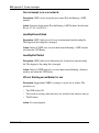
How to get help . . . . . . . . . . . . . . . . . . . . . . . . . . . . . . . . . . . . . . . . . . . . . . . . . . . . . . 22
Finding the latest updates on the Nortel Web site . . . . . . . . . . . . . . . . . . . . . . . . . 22
Getting help from the Nortel Web site . . . . . . . . . . . . . . . . . . . . . . . . . . . . . . . . . . 23
Getting help over the phone from a Nortel Solutions Center . . . . . . . . . . . . . . . . . 23
Getting help from a specialist by using an Express Routing Code . . . . . . . . . . . . 23
Getting help through a Nortel distributor or reseller . . . . . . . . . . . . . . . . . . . . . . . . 24
New in this release. . . . . . . . . . . . . . . . . . . . . . . . . . . . . . . . . . . . . . . . . . . . . 25
Features . . . . . . . . . . . . . . . . . . . . . . . . . . . . . . . . . . . . . . . . . . . . . . . . . . . . . . . . . . . . 25
SNMP traps when an IP address pool reaches the configured threshold . . . . . . . 25
Automatic backups . . . . . . . . . . . . . . . . . . . . . . . . . . . . . . . . . . . . . . . . . . . . . . . . 26
PCAP enhancements . . . . . . . . . . . . . . . . . . . . . . . . . . . . . . . . . . . . . . . . . . . . . . 26
SNMP interface index enhancement . . . . . . . . . . . . . . . . . . . . . . . . . . . . . . . . . . . 26
Chapter 1
VPN Router administration . . . . . . . . . . . . . . . . . . . . . . . . . . . . . . . . . . . . . . 27
Administrator settings . . . . . . . . . . . . . . . . . . . . . . . . . . . . . . . . . . . . . . . . . . . . . . . . . . 27
Lost user name and password—resetting the VPN Router to factory defaults . . . 28
Dynamic password . . . . . . . . . . . . . . . . . . . . . . . . . . . . . . . . . . . . . . . . . . . . . . . . . . . . 29
Tools . . . . . . . . . . . . . . . . . . . . . . . . . . . . . . . . . . . . . . . . . . . . . . . . . . . . . . . . . . . . . . . 29
System configuration . . . . . . . . . . . . . . . . . . . . . . . . . . . . . . . . . . . . . . . . . . . . . . . . . . 30
File management . . . . . . . . . . . . . . . . . . . . . . . . . . . . . . . . . . . . . . . . . . . . . . . . . . . . . 30
Simple Network Management Protocol (SNMP) . . . . . . . . . . . . . . . . . . . . . . . . . . . . . 31
Nortel VPN Router Troubleshooting
6 Contents
Configuring SNMP traps to send notification when an IP address pool reaches the
configured threshold . . . . . . . . . . . . . . . . . . . . . . . . . . . . . . . . . . . . . . . . . . . . . . 32
Chapter 2
Status and logging. . . . . . . . . . . . . . . . . . . . . . . . . . . . . . . . . . . . . . . . . . . . . 35
Sessions . . . . . . . . . . . . . . . . . . . . . . . . . . . . . . . . . . . . . . . . . . . . . . . . . . . . . . . . . . . . 36
Reports . . . . . . . . . . . . . . . . . . . . . . . . . . . . . . . . . . . . . . . . . . . . . . . . . . . . . . . . . . . . 36
System . . . . . . . . . . . . . . . . . . . . . . . . . . . . . . . . . . . . . . . . . . . . . . . . . . . . . . . . . . . . . 37
Health check . . . . . . . . . . . . . . . . . . . . . . . . . . . . . . . . . . . . . . . . . . . . . . . . . . . . . . . . 37
Statistics . . . . . . . . . . . . . . . . . . . . . . . . . . . . . . . . . . . . . . . . . . . . . . . . . . . . . . . . . . . . 37
Accounting . . . . . . . . . . . . . . . . . . . . . . . . . . . . . . . . . . . . . . . . . . . . . . . . . . . . . . . . . . 38
Accounting records . . . . . . . . . . . . . . . . . . . . . . . . . . . . . . . . . . . . . . . . . . . . . . . . 38
RADIUS accounting . . . . . . . . . . . . . . . . . . . . . . . . . . . . . . . . . . . . . . . . . . . . . . . . 39
Data collection task . . . . . . . . . . . . . . . . . . . . . . . . . . . . . . . . . . . . . . . . . . . . . . . . 39
Logs . . . . . . . . . . . . . . . . . . . . . . . . . . . . . . . . . . . . . . . . . . . . . . . . . . . . . . . . . . . . . . . 41
Event log . . . . . . . . . . . . . . . . . . . . . . . . . . . . . . . . . . . . . . . . . . . . . . . . . . . . . . . . 41
System log . . . . . . . . . . . . . . . . . . . . . . . . . . . . . . . . . . . . . . . . . . . . . . . . . . . . . . . 45
Security log . . . . . . . . . . . . . . . . . . . . . . . . . . . . . . . . . . . . . . . . . . . . . . . . . . . . . . 45
Configuration log . . . . . . . . . . . . . . . . . . . . . . . . . . . . . . . . . . . . . . . . . . . . . . . . . . 46
Chapter 3
Administrative tasks . . . . . . . . . . . . . . . . . . . . . . . . . . . . . . . . . . . . . . . . . . . 47
Shutdown . . . . . . . . . . . . . . . . . . . . . . . . . . . . . . . . . . . . . . . . . . . . . . . . . . . . . . . . . . . 47
Recovery . . . . . . . . . . . . . . . . . . . . . . . . . . . . . . . . . . . . . . . . . . . . . . . . . . . . . . . . . . . 48
Accessing the diskette drive . . . . . . . . . . . . . . . . . . . . . . . . . . . . . . . . . . . . . . . . . 48
Using the recovery diskette . . . . . . . . . . . . . . . . . . . . . . . . . . . . . . . . . . . . . . . . . . 48
Automatic backups . . . . . . . . . . . . . . . . . . . . . . . . . . . . . . . . . . . . . . . . . . . . . . . . . . . . 52
Using the GUI for automatic backup . . . . . . . . . . . . . . . . . . . . . . . . . . . . . . . . . . . 53
Transferring backup files through SFTP . . . . . . . . . . . . . . . . . . . . . . . . . . . . . 53
Triggering a backup when a file or directory changes . . . . . . . . . . . . . . . . . . . 53
Using the CLI for automatic backup . . . . . . . . . . . . . . . . . . . . . . . . . . . . . . . . . . . . 57
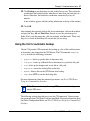
Backing up specific files and directories . . . . . . . . . . . . . . . . . . . . . . . . . . . . . 58
Stopping the backup of specific files and directories . . . . . . . . . . . . . . . . . . . 58
Backing up changes to specific files or directories . . . . . . . . . . . . . . . . . . . . . 58
Stopping the backup of changes to specific files or directories . . . . . . . . . . . . 59
NN46110-602
Contents 7
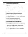
Using SFTP to transfer backup files . . . . . . . . . . . . . . . . . . . . . . . . . . . . . . . . 59
Stopping the transfer of backup files using SFTP . . . . . . . . . . . . . . . . . . . . . . 59
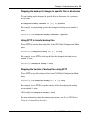
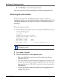
Disabling new logins . . . . . . . . . . . . . . . . . . . . . . . . . . . . . . . . . . . . . . . . . . . . . . . . . . 60
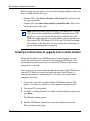
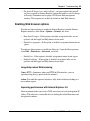
Upgrading the software . . . . . . . . . . . . . . . . . . . . . . . . . . . . . . . . . . . . . . . . . . . . . . . . 60
Checking available disk space . . . . . . . . . . . . . . . . . . . . . . . . . . . . . . . . . . . . . . . . 61
Creating a control tunnel to upgrade from a remote location . . . . . . . . . . . . . . . . . 62
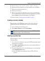
Creating a recovery diskette . . . . . . . . . . . . . . . . . . . . . . . . . . . . . . . . . . . . . . . . . 63
Backing up system files . . . . . . . . . . . . . . . . . . . . . . . . . . . . . . . . . . . . . . . . . . . . . 63
Retrieving the new software . . . . . . . . . . . . . . . . . . . . . . . . . . . . . . . . . . . . . . . . . 64
Before completing the upgrade . . . . . . . . . . . . . . . . . . . . . . . . . . . . . . . . . . . . . . . 66
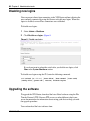
Applying the software . . . . . . . . . . . . . . . . . . . . . . . . . . . . . . . . . . . . . . . . . . . . . . 67
After you upgrade the software . . . . . . . . . . . . . . . . . . . . . . . . . . . . . . . . . . . . . . . 67
Chapter 4
Troubleshooting . . . . . . . . . . . . . . . . . . . . . . . . . . . . . . . . . . . . . . . . . . . . . . . 69
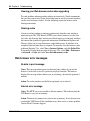
Troubleshooting tools . . . . . . . . . . . . . . . . . . . . . . . . . . . . . . . . . . . . . . . . . . . . . . . . . . 70
Client-based tools . . . . . . . . . . . . . . . . . . . . . . . . . . . . . . . . . . . . . . . . . . . . . . . . . 70
System-based tools . . . . . . . . . . . . . . . . . . . . . . . . . . . . . . . . . . . . . . . . . . . . . . . . 71
Other tools . . . . . . . . . . . . . . . . . . . . . . . . . . . . . . . . . . . . . . . . . . . . . . . . . . . . . . . 71
Solving connectivity problems . . . . . . . . . . . . . . . . . . . . . . . . . . . . . . . . . . . . . . . . . . . 72
Diagnosing client connectivity problems . . . . . . . . . . . . . . . . . . . . . . . . . . . . . . . . 72
Common client connectivity problems . . . . . . . . . . . . . . . . . . . . . . . . . . . . . . . . . . 73
Problems with name resolution using DNS services . . . . . . . . . . . . . . . . . . . . . . . 76
Network browsing problems . . . . . . . . . . . . . . . . . . . . . . . . . . . . . . . . . . . . . . . . . 77
Diagnosing WAN link problems . . . . . . . . . . . . . . . . . . . . . . . . . . . . . . . . . . . . . . . 79
Hardware encryption accelerator connectivity . . . . . . . . . . . . . . . . . . . . . . . . . . . . 82
Solving performance problems . . . . . . . . . . . . . . . . . . . . . . . . . . . . . . . . . . . . . . . . . . 82
Eliminating modem errors . . . . . . . . . . . . . . . . . . . . . . . . . . . . . . . . . . . . . . . . . . . 82
Performance tips for configuring Microsoft networking . . . . . . . . . . . . . . . . . . . . . . . . 82
Additional information . . . . . . . . . . . . . . . . . . . . . . . . . . . . . . . . . . . . . . . . . . . . . . 91
Solving general problems . . . . . . . . . . . . . . . . . . . . . . . . . . . . . . . . . . . . . . . . . . . . . . . 92
Web browser problems and the VPN Client Manager . . . . . . . . . . . . . . . . . . . . . . 92
Enabling Web browser options . . . . . . . . . . . . . . . . . . . . . . . . . . . . . . . . . . . . . . . 93
Web browser error messages . . . . . . . . . . . . . . . . . . . . . . . . . . . . . . . . . . . . . . . . 94
Reporting a problem with a Web browser . . . . . . . . . . . . . . . . . . . . . . . . . . . . . . . 96
Nortel VPN Router Troubleshooting
8 Contents
System problems . . . . . . . . . . . . . . . . . . . . . . . . . . . . . . . . . . . . . . . . . . . . . . . . . . 96
Solving routing problems . . . . . . . . . . . . . . . . . . . . . . . . . . . . . . . . . . . . . . . . . . . . . . . 98
Client address redistribution problems . . . . . . . . . . . . . . . . . . . . . . . . . . . . . . . . . 98
Solving firewall problems . . . . . . . . . . . . . . . . . . . . . . . . . . . . . . . . . . . . . . . . . . . . . . . 99
Chapter 5
Packet capture . . . . . . . . . . . . . . . . . . . . . . . . . . . . . . . . . . . . . . . . . . . . . . . 103
PCAP features . . . . . . . . . . . . . . . . . . . . . . . . . . . . . . . . . . . . . . . . . . . . . . . . . . . 104
Security features . . . . . . . . . . . . . . . . . . . . . . . . . . . . . . . . . . . . . . . . . . . . . . 105
File format . . . . . . . . . . . . . . . . . . . . . . . . . . . . . . . . . . . . . . . . . . . . . . . . . . . . . . 105
Capture types . . . . . . . . . . . . . . . . . . . . . . . . . . . . . . . . . . . . . . . . . . . . . . . . . . . 106
Physical interface captures . . . . . . . . . . . . . . . . . . . . . . . . . . . . . . . . . . . . . . 106
Tunnel captures . . . . . . . . . . . . . . . . . . . . . . . . . . . . . . . . . . . . . . . . . . . . . . . 106
Global IP captures . . . . . . . . . . . . . . . . . . . . . . . . . . . . . . . . . . . . . . . . . . . . . 107
Filters and triggers . . . . . . . . . . . . . . . . . . . . . . . . . . . . . . . . . . . . . . . . . . . . . . . . 108
Capture filters . . . . . . . . . . . . . . . . . . . . . . . . . . . . . . . . . . . . . . . . . . . . . . . . 108
Triggers . . . . . . . . . . . . . . . . . . . . . . . . . . . . . . . . . . . . . . . . . . . . . . . . . . . . . 108
Saving captured data . . . . . . . . . . . . . . . . . . . . . . . . . . . . . . . . . . . . . . . . . . . . . . 109
Memory considerations . . . . . . . . . . . . . . . . . . . . . . . . . . . . . . . . . . . . . . . . . . . . 109
Performance considerations . . . . . . . . . . . . . . . . . . . . . . . . . . . . . . . . . . . . . . . . 110
Enabling packet capture on a VPN Router . . . . . . . . . . . . . . . . . . . . . . . . . . . . . 111
Capturing packets to disk file . . . . . . . . . . . . . . . . . . . . . . . . . . . . . . . . . . . . . . . . 113
Setting the PCAP file path . . . . . . . . . . . . . . . . . . . . . . . . . . . . . . . . . . . . . . . 113
Setting the size of the RAM buffer . . . . . . . . . . . . . . . . . . . . . . . . . . . . . . . . . 114
Setting the size of a disk capture file . . . . . . . . . . . . . . . . . . . . . . . . . . . . . . . 114
Setting the maximum number of disk capture files . . . . . . . . . . . . . . . . . . . . 114
Saving captured data . . . . . . . . . . . . . . . . . . . . . . . . . . . . . . . . . . . . . . . . . . 115
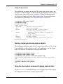
Configuring and running packet capture objects . . . . . . . . . . . . . . . . . . . . . . . . . 115
Creating a capture object . . . . . . . . . . . . . . . . . . . . . . . . . . . . . . . . . . . . . . . 115
Starting, stopping, and saving capture objects . . . . . . . . . . . . . . . . . . . . . . . 119
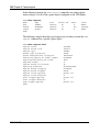
Using the show capture command to display capture status . . . . . . . . . . . . 119
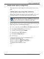
Sample packet capture configurations . . . . . . . . . . . . . . . . . . . . . . . . . . . . . . . . . 121
Interface capture object using a filter and direction . . . . . . . . . . . . . . . . . . . . 121
Interface capture object using triggers . . . . . . . . . . . . . . . . . . . . . . . . . . . . . 122
Tunnel capture object using a remote IP address . . . . . . . . . . . . . . . . . . . . . 124
NN46110-602
Contents 9
Viewing a packet capture output file on a PC . . . . . . . . . . . . . . . . . . . . . . . . . . . 125
Installing Ethereal software . . . . . . . . . . . . . . . . . . . . . . . . . . . . . . . . . . . . . . . . . 125
Saving, downloading, and viewing PCAP files . . . . . . . . . . . . . . . . . . . . . . . . . . 126
Viewing a PCAP file with Sniffer Pro . . . . . . . . . . . . . . . . . . . . . . . . . . . . . . . . . . 127
Deleting capture objects and disabling packet capture . . . . . . . . . . . . . . . . . . . . 128
Appendix A
MIB support . . . . . . . . . . . . . . . . . . . . . . . . . . . . . . . . . . . . . . . . . . . . . . . . . 131
SNMP RFC support . . . . . . . . . . . . . . . . . . . . . . . . . . . . . . . . . . . . . . . . . . . . . . . . . . 131
Novell IPX MIB . . . . . . . . . . . . . . . . . . . . . . . . . . . . . . . . . . . . . . . . . . . . . . . . . . . 131
Novell RIP-SAP MIB . . . . . . . . . . . . . . . . . . . . . . . . . . . . . . . . . . . . . . . . . . . . . . 131
RFC 1850—OSPF Version 2 Management Information Base . . . . . . . . . . . . . . . 131
RFC 1724—RIP Version 2 MIB Extension . . . . . . . . . . . . . . . . . . . . . . . . . . . . . . 132
RFC 1213—Network Management of TCP/IP-Based Internets MIB . . . . . . . . . . 132
RFC 2667—IP Tunnel MIB . . . . . . . . . . . . . . . . . . . . . . . . . . . . . . . . . . . . . . . . . 132
RFC 2787—VRRP MIB . . . . . . . . . . . . . . . . . . . . . . . . . . . . . . . . . . . . . . . . . . . . 133
RFC 2737—Entity MIB . . . . . . . . . . . . . . . . . . . . . . . . . . . . . . . . . . . . . . . . . . . . 133
RFC 1573—IanaIfType MIB . . . . . . . . . . . . . . . . . . . . . . . . . . . . . . . . . . . . . . . . . 134
RFC 2233—If MIB . . . . . . . . . . . . . . . . . . . . . . . . . . . . . . . . . . . . . . . . . . . . . . . . 134
RFC 2571—Snmp-Framework MIB . . . . . . . . . . . . . . . . . . . . . . . . . . . . . . . . . . . 134
RFC2790—Host Resources MIB . . . . . . . . . . . . . . . . . . . . . . . . . . . . . . . . . . . . . 134
RFC2495—DS1 MIB . . . . . . . . . . . . . . . . . . . . . . . . . . . . . . . . . . . . . . . . . . . . . . 135
RFC2863 Interface MIB (64 bit counters support) . . . . . . . . . . . . . . . . . . . . . . . . 136
VPN Router MIB . . . . . . . . . . . . . . . . . . . . . . . . . . . . . . . . . . . . . . . . . . . . . . . . . 136
cestraps.mib—Nortel proprietary MIB . . . . . . . . . . . . . . . . . . . . . . . . . . . . . . . . . . . . 137
newoak.mib . . . . . . . . . . . . . . . . . . . . . . . . . . . . . . . . . . . . . . . . . . . . . . . . . . . . . . . . 139
Hardware-related traps . . . . . . . . . . . . . . . . . . . . . . . . . . . . . . . . . . . . . . . . . . . . 140
Server-related traps . . . . . . . . . . . . . . . . . . . . . . . . . . . . . . . . . . . . . . . . . . . . . . . 144
Software-related traps . . . . . . . . . . . . . . . . . . . . . . . . . . . . . . . . . . . . . . . . . . . . . 146
Login-related traps . . . . . . . . . . . . . . . . . . . . . . . . . . . . . . . . . . . . . . . . . . . . . . . . 146
Intrusion-related traps . . . . . . . . . . . . . . . . . . . . . . . . . . . . . . . . . . . . . . . . . . . . . 147
System-related traps . . . . . . . . . . . . . . . . . . . . . . . . . . . . . . . . . . . . . . . . . . . . . . 147
Information passed with every trap . . . . . . . . . . . . . . . . . . . . . . . . . . . . . . . . . . . 148
Nortel VPN Router Troubleshooting
10 Contents
Appendix B
Using serial PPP . . . . . . . . . . . . . . . . . . . . . . . . . . . . . . . . . . . . . . . . . . . . . 165
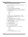
Establishing a serial PPP connection . . . . . . . . . . . . . . . . . . . . . . . . . . . . . . . . . . . . . 165
Setting up a Dial-Up Networking connection . . . . . . . . . . . . . . . . . . . . . . . . . . . . 166
Setting up the modem . . . . . . . . . . . . . . . . . . . . . . . . . . . . . . . . . . . . . . . . . . 167
Setting up the VPN Router . . . . . . . . . . . . . . . . . . . . . . . . . . . . . . . . . . . . . . . . . 167
Dialing in to the VPN Router . . . . . . . . . . . . . . . . . . . . . . . . . . . . . . . . . . . . . . . . 169
Troubleshooting Serial PPP . . . . . . . . . . . . . . . . . . . . . . . . . . . . . . . . . . . . . . . . . . . . 169
PPP option settings . . . . . . . . . . . . . . . . . . . . . . . . . . . . . . . . . . . . . . . . . . . . . . . . . . 171
Appendix C
System messages . . . . . . . . . . . . . . . . . . . . . . . . . . . . . . . . . . . . . . . . . . . . 173
Certificate messages . . . . . . . . . . . . . . . . . . . . . . . . . . . . . . . . . . . . . . . . . . . . . . . . . 173
ISAKMP messages . . . . . . . . . . . . . . . . . . . . . . . . . . . . . . . . . . . . . . . . . . . . . . . . . . 175
Branch office messages . . . . . . . . . . . . . . . . . . . . . . . . . . . . . . . . . . . . . . . . . . . . . . . 178
SSL messages . . . . . . . . . . . . . . . . . . . . . . . . . . . . . . . . . . . . . . . . . . . . . . . . . . . . . . 179
Database messages . . . . . . . . . . . . . . . . . . . . . . . . . . . . . . . . . . . . . . . . . . . . . . . . . 180
Security messages . . . . . . . . . . . . . . . . . . . . . . . . . . . . . . . . . . . . . . . . . . . . . . . . . . . 181
RADIUS accounting messages . . . . . . . . . . . . . . . . . . . . . . . . . . . . . . . . . . . . . . . . . 191
RADIUS authentication messages . . . . . . . . . . . . . . . . . . . . . . . . . . . . . . . . . . . . . . . 194
Routing messages . . . . . . . . . . . . . . . . . . . . . . . . . . . . . . . . . . . . . . . . . . . . . . . . . . . 198
Hardware messages . . . . . . . . . . . . . . . . . . . . . . . . . . . . . . . . . . . . . . . . . . . . . . . . . 204
Appendix D
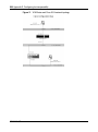
Configuring for interoperability . . . . . . . . . . . . . . . . . . . . . . . . . . . . . . . . . 207
Configuring the Cisco 2514 router, Version 11.3 . . . . . . . . . . . . . . . . . . . . . . . . . . . . 207
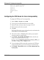
Configuring the VPN Router for Cisco interoperability . . . . . . . . . . . . . . . . . . . . . . . . 210
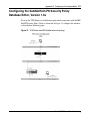
Configuring the SafeNet/Soft-PK Security Policy Database Editor, Version 1.0s . . . . 211
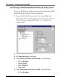
Connecting to IRE SafeNET/Soft-PK Security Policy Client . . . . . . . . . . . . . . . . 212
Configuring the VPN Router for IRE interoperability . . . . . . . . . . . . . . . . . . . . . . . . . 215
Third-party client installation . . . . . . . . . . . . . . . . . . . . . . . . . . . . . . . . . . . . . . . . . . . 216
Considerations for using third-party clients . . . . . . . . . . . . . . . . . . . . . . . . . . . . . 217
Configuring the VPN Router as a branch office tunnel . . . . . . . . . . . . . . . . . . . . 219
Configuring the VPN Router as a user tunnel . . . . . . . . . . . . . . . . . . . . . . . . . . . 220
Configuring IPX . . . . . . . . . . . . . . . . . . . . . . . . . . . . . . . . . . . . . . . . . . . . . . . . . . . . . 222
NN46110-602
Contents 11
IPX client . . . . . . . . . . . . . . . . . . . . . . . . . . . . . . . . . . . . . . . . . . . . . . . . . . . . . . . 223
Windows 95 and Windows 98 . . . . . . . . . . . . . . . . . . . . . . . . . . . . . . . . . . . . 224
Windows NT . . . . . . . . . . . . . . . . . . . . . . . . . . . . . . . . . . . . . . . . . . . . . . . . . 224
IPX group configuration . . . . . . . . . . . . . . . . . . . . . . . . . . . . . . . . . . . . . . . . . . . . 224
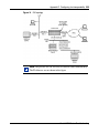
Sample IPX VPN Router topology . . . . . . . . . . . . . . . . . . . . . . . . . . . . . . . . . . . . 224
Index . . . . . . . . . . . . . . . . . . . . . . . . . . . . . . . . . . . . . . . . . . . . . . . . . . . . . . . 227
Nortel VPN Router Troubleshooting
12 Contents
NN46110-602
13
Figures
Figure 1
Admin > SNMP Traps window . . . . . . . . . . . . . . . . . . . . . . . . . . . . . . . . . 33
Figure 2
Event logs . . . . . . . . . . . . . . . . . . . . . . . . . . . . . . . . . . . . . . . . . . . . . . . . . 42
Figure 3
Capture and display filters . . . . . . . . . . . . . . . . . . . . . . . . . . . . . . . . . . . . 43
Figure 4
Configure Display Entity
Figure 5
Recovery Diskette window . . . . . . . . . . . . . . . . . . . . . . . . . . . . . . . . . . . . 49
Figure 6
Automatic backup window . . . . . . . . . . . . . . . . . . . . . . . . . . . . . . . . . . . . 54
Figure 7
Specific Automatic Backup window . . . . . . . . . . . . . . . . . . . . . . . . . . . . . 56
Figure 8
Disable new logins . . . . . . . . . . . . . . . . . . . . . . . . . . . . . . . . . . . . . . . . . . 60
Figure 9
FTP menu example . . . . . . . . . . . . . . . . . . . . . . . . . . . . . . . . . . . . . . . . . 65
Figure 10
FTP menu with subdirectory example . . . . . . . . . . . . . . . . . . . . . . . . . . . 65
Figure 11
VPN Router and Cisco 2514 network topology . . . . . . . . . . . . . . . . . . . 208
Figure 12
VPN Router and IRE SafeNet network topology . . . . . . . . . . . . . . . . . . 211
Figure 13
Split tunneling example . . . . . . . . . . . . . . . . . . . . . . . . . . . . . . . . . . . . . . 221
Figure 14
IPX topology . . . . . . . . . . . . . . . . . . . . . . . . . . . . . . . . . . . . . . . . . . . . . . 225
. . . . . . . . . . . . . . . . . . . . . . . . . . . . . . . . . . . . . 44
Nortel VPN Router Troubleshooting
14 Figures
NN46110-602
15
Tables
Table 1
Field IDs for data collection records . . . . . . . . . . . . . . . . . . . . . . . . . . . . . 40
Table 2
Troubleshooting tools . . . . . . . . . . . . . . . . . . . . . . . . . . . . . . . . . . . . . . . . 71
Table 3
Trap categories . . . . . . . . . . . . . . . . . . . . . . . . . . . . . . . . . . . . . . . . . . . . 149
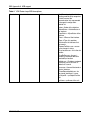
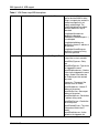
Table 4
VPN Router traps MIB descriptions . . . . . . . . . . . . . . . . . . . . . . . . . . . . 150
Table 5
DIP switch configuration . . . . . . . . . . . . . . . . . . . . . . . . . . . . . . . . . . . . . 167
Nortel VPN Router Troubleshooting
16 Tables
NN46110-602
17
Preface
This guide provides information about how to manage and troubleshoot the Nortel
VPN Router.
Before you begin
This guide is for network managers who monitor and maintain the Nortel VPN
Router. This guide assumes that you have experience with system administration
and familiarity with network management.
Text conventions
This guide uses the following text conventions:
angle brackets (< >)
Indicate that you choose the text to enter based on the
description inside the brackets. Do not type the
brackets when entering the command.
Example: If the command syntax is
ping <ip_address>, you enter
ping 192.32.10.12
bold Courier text
Indicates command names and options and text that
you need to enter.
Example: Use the show health command.
Example: Enter terminal paging {off | on}.
Nortel VPN Router Troubleshooting
18
Preface
braces ({})
Indicate required elements in syntax descriptions where
there is more than one option. You must choose only
one of the options. Do not type the braces when
entering the command.
Example: If the command syntax is ldap-server
source {external | internal}, you must enter
either ldap-server source external or
ldap-server source internal, but not both.
brackets ([ ])
Indicate optional elements in syntax descriptions. Do
not type the brackets when entering the command.
Example: If the command syntax is
show ntp [associations], you can enter
either show ntp or show ntp associations.
Example: If the command syntax is default rsvp
[token-bucket {depth | rate}], you can enter
default rsvp, default rsvp token-bucket
depth, or default rsvp token-bucket rate.
ellipsis points (. . . )
Indicate that you repeat the last element of the
command as needed.
Example: If the command syntax is
more diskn:<directory>/...<file_name>,
you enter more and the fully qualified name of the file.
NN46110-602
italic text
Indicates new terms, book titles, and variables in
command syntax descriptions. Where a variable is two
or more words, the words are connected by an
underscore.
Example: If the command syntax is
ping <ip_address>, ip_address is one variable
and you substitute one value for it.
plain Courier
text
Indicates system output, for example, prompts and
system messages.
Example: File not found.
separator ( > )
Shows menu paths.
Example: Choose Status > Health Check.
Preface 19
vertical line ( | )
Separates choices for command keywords and
arguments. Enter only one of the choices. Do not type
the vertical line when entering the command.
Example: If the command syntax is
terminal paging {off | on}, you enter either
terminal paging off or terminal paging on,
but not both.
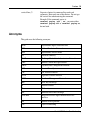
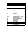
Acronyms
This guide uses the following acronyms:
ADSL
asynchronous digital subscriber line
ARP
Address Resolution Protocol
ATM
asynchronous transfer mode
CA
certificate authority
CHAP
Challenge Handshake Authentication Protocol
CMP
Internet Control Message Protocol
DHCP
Dynamic Host Configuration Protocol
DNS
Domain Name System
FTP
File Transfer Protocol
HTTP
Hypertext Transfer Protocol
ICMP
Certificate Management Protocol
IKE
IPsec Key Exchange
IP
Internet Protocol
IPsec
IP Security
IPX
Internetwork Packet Exchange
ISDN BRI
integrated services digital network basic-rate
interface
ISP
Internet service provider
L2F
Layer 2 Forwarding
Nortel VPN Router Troubleshooting
20
Preface
NN46110-602
L2TP
Layer 2 Tunneling Protocol
LAN
local area network
LDAP
Lightweight Directory Access Protocol
NAT
Network Address Translation
OSI
Open Systems Interconnection
OSPF
Open Shortest Path First
PAP
Password Authentication Protocol
PCAP
packet capture
PDN
public data network
POP
point of presence
PPP
Point-to-Point Protocol
PPTP
Point-to-Point Tunneling Protocol
RADIUS
Remote Authentication Dial-In User Service
RIP
Routing Information Protocol
SNMP
Simple Network Management Protocol
UDP
User Datagram Protocol
URL
uniform resource locator
VPN
virtual private network
VRRP
Virtual Router Redundancy Protocol
WAN
wide area network
XNS
Xerox Networking System
Preface 21
Related publications
For more information about the Nortel VPN Router, see the following
publications:
•
•
•
•
•
•
•
•
•
•
Release notes provide the latest information, including brief descriptions of
the new features, problems fixed in this release, and known problems and
workarounds.
Nortel VPN Router Configuration — Basic Features (NN46110-500)
introduces the product and provides information about initial setup and
configuration.
Nortel VPN Router Configuration — SSL VPN Services (NN46110-501)
provides instructions for configuring services on the SSL VPN Module 1000,
including authentication, networks, user groups, and portal links.
Nortel VPN Router Security — Servers, Authentication, and Certificates
(NN46110-600) provides instructions for configuring authentication services
and digital certificates.
Nortel VPN Router Security — Firewalls, Filters, NAT, and QoS
(NN46110-601) provides instructions for configuring the Stateful Firewall
and VPN Router interface and tunnel filters.
Nortel VPN Router Configuration — Advanced Features (NN46110-502)
provides instructions for configuring advanced LAN and WAN settings, PPP,
frame relay, PPPoE, ADSL and ATM, T1CSU/DSU, dial services and BIS,
DLSw, IPX, and SSL VPN.
Nortel VPN Router Configuration — Tunneling Protocols (NN46110-503)
configuration information for the tunneling protocols IPsec, L2TP, PPTP, and
L2F.
Nortel VPN Router Configuration—Routing (NN46110-504) provides
instructions for configuring RIP, OSPF, and VRRP, as well as instructions for
configuring ECMP, routing policy services, and client address redistribution
(CAR).
Nortel VPN Router Using the Command Line Interface (NN46110-507)
provides syntax, descriptions, and examples for the commands that you can
use from the command line interface.
Nortel VPN Router Configuration — TunnelGuard (NN46110-307) provides
information about configuring and using the TunnelGuard feature.
Nortel VPN Router Troubleshooting
22
Preface
Hard-copy technical manuals
You can print selected technical manuals and release notes free, directly from the
Internet. Go to www.nortelnetworks.com/documentation, find the product for
which you need documentation, then locate the specific category and model or
version for your hardware or software product. Use Adobe Reader to open the
manuals and release notes, search for the sections you need, and print them on
most standard printers. Go to the Adobe Web site at the www.adobe.com to
download a free copy of the Adobe Reader.
How to get help
This section explains how to get help for Nortel products and services.
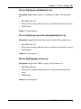
Finding the latest updates on the Nortel Web site
The content of this documentation was current at the time the product was
released. To check for updates to the latest documentation and software for VPN
Router, click one of the following links:
Link to
Takes you directly to the
Latest software
Nortel page for VPN Router software located at:
www130.nortelnetworks.com/cgi-bin/eserv/cs/
main.jsp?cscat=SOFTWARE&resetFilter=1&poid
=12325
Latest documentation
Nortel page for VPN Router documentation
located at:
www130.nortelnetworks.com/cgi-bin/eserv/cs/
main.jsp?cscat=DOCUMENTATION&resetFilter=
1&poid=12325
NN46110-602
Preface 23
Getting help from the Nortel Web site
The best way to get technical support for Nortel products is from the Nortel
Technical Support Web site:
www.nortel.com/support
This site provides quick access to software, documentation, bulletins, and tools to
address issues with Nortel products. From this site, you can:
•
•
•
•
download software, documentation, and product bulletins
search the Technical Support Web site and the Nortel Knowledge Base for
answers to technical issues
sign up for automatic notification of new software and documentation for
Nortel equipment
open and manage technical support cases
Getting help over the phone from a Nortel Solutions Center
If you do not find the information you require on the Nortel Technical Support
Web site, and you have a Nortel support contract, you can also get help over the
phone from a Nortel Solutions Center.
In North America, call 1-800-4NORTEL (1-800-466-7835).
Outside North America, go to the following web site to obtain the phone number
for your region:
www.nortel.com/callus
Getting help from a specialist by using an Express Routing
Code
To access some Nortel Technical Solutions Centers, you can use an Express
Routing Code (ERC) to quickly route your call to a specialist in your Nortel
product or service. To locate the ERC for your product or service, go to:
www.nortel.com/erc
Nortel VPN Router Troubleshooting
24
Preface
Getting help through a Nortel distributor or reseller
If you purchased a service contract for your Nortel product from a distributor or
authorized reseller, contact the technical support staff for that distributor or
reseller.
NN46110-602
25
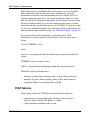
New in this release
The following section details what is new in Nortel VPN Router Troubleshooting
for Release 7.0.
Features
See the following sections for information about feature changes:
•
•
•
•
SNMP traps when an IP address pool reaches the configured threshold
Automatic backups
PCAP enhancements
SNMP interface index enhancement
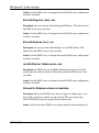
SNMP traps when an IP address pool reaches the
configured threshold
You can configure the VPN Router so that a Simple Network Management
Protocol (SNMP) trap sends a notification about an exhausted pool when a
defined IP address pool reaches a configured limit. The list of IP address pools is
periodically traversed and sends a trap if any pool is over the quota. You can set
the limit and the default is 70%.
For more information about trap notification when the IP pool reaches a certain
capacity, see “Configuring SNMP traps to send notification when an IP address
pool reaches the configured threshold” on page 32.
Nortel VPN Router Troubleshooting
26
New in this release
Automatic backups
You can now back up a file or a directory, as well as trigger a backup, when a file
changes. Previously, you could only back up system, configuration, and log files.
You can use either the graphical user interface (GUI) or the command line
interface (CLI) to configure automated backup.
You can also now use a Secure File Transfer Protocol (SFTP) client as well as File
Transfer Protocol (FTP) to transfer backup files. You can use either the GUI or the
CLI to activate SFTP.
For more information about automatic backups, see “Automatic backups” on
page 52.
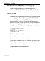
PCAP enhancements
You can now capture packets to disk files. Previously, you could capture packets
to random access memory (RAM) only. There are five new commands for the
command line interface (CLI) of the VPN Router. You must use the CLI to
configure Packet Capture (PCAP).
For more information about PCAP enhancements, see “Capturing packets to disk
file” on page 113.
SNMP interface index enhancement
Third-party network management systems (NMS) rely on interface index
(IfIndex) numbers to monitor and gather statistics for devices through SNMP.
These locally significant numbers are assigned to the physical and virtual
interfaces on the device and enable the NMS to associate statistics with interfaces.
Previously, when a branch office tunnel came up, it was assigned a dynamic
IfIndex number. Only up tunnels were reported; any down tunnels were not
reported.
With the enhancement, each branch office is assigned a static IfIndex, the IfIndex
is saved in LDAP, and tunnels are reported even when they are down.
For more information about the IfIndex enhancement, see “RFC 1213—Network
Management of TCP/IP-Based Internets MIB” on page 132.
NN46110-602
27
Chapter 1
VPN Router administration
This chapter introduces administrator settings, tools, system configuration, and
file management. It also includes information about SNMP traps.
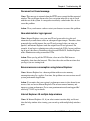
Administrator settings
The VPN Router supports multiple administrators. You can assign different rights
to allow or prevent administrative users from managing or viewing the VPN
Router and user configuration information. You assign administrative privileges
and rights on the Profiles > User > Edit window. The VPN Router also supports a
primary administrator.
You can assign one of the following priviledge levels to the Manage Switch and
Manage Users:
•
•
•
•
None—This user does not have administrator rights to manage the VPN
Router or to manage users; the user cannot view or manage configuration or
user settings.
View—This user has administrator rights to view (monitor) VPN Router
configuration or user rights settings; however, the user cannot manage
(change) them. This is the lowest level of administrator rights.
Manage—This user has administrator rights to view (monitor) and manage
(configure) other VPN Router configuration or user rights settings. This is the
highest level of administrative rights.
Add Subgroups is a check box that gives the user the authority to add and
delete subgroups under the given directory when the user has View only
authority with Manage Switch access rights.
Nortel VPN Router Troubleshooting
28 Chapter 1 VPN Router administration
You use the Administrator Settings window to do the following:
•
•
•
•
change the primary administrator user ID and password
control the Administrator Idle Timeout Setting for all administrators
control the default language
control the serial port settings
There is only one primary administrator. The primary administrator user ID and
password combination do the following:
•
•
provide the user with access to all windows and control settings
allows access to the serial port and the recovery disk
Note: Once you set the primary administrator user ID and password,
you must implement an Admin > Shutdown to save the new settings.
Doing a reset (using the Reset button on the back of the VPN Router)
does not save the settings.
You can change the primary administrator user ID and password on the Admin >
Administrator window.
Lost user name and password—resetting the VPN Router to
factory defaults
You can set the VPN Router back to the factory default configuration even if you
do not know the administrator username and password. To do this:
1
Boot the VPN Router into recovery mode.
2
Open a browser to the management IP address of the VPN Router. You do not
need a user name and password for this step.
3
Reset to factory default. After you reset to factory default, the administrator
user name is admin and the password is setup.
Caution: Resetting to factory default removes all existing configuration
information.
NN46110-602
Chapter 1 VPN Router administration 29
Dynamic password
Two types of administrative users exist on the VPN Router:
•
•
one super-user (Administrator)
as many administrative users as needed
There is dynamic password support for administrative users only. The
Administrator still requires a static password.
RADIUS manages the dynamic password. The external RADIUS service acts as
an intermediary between the VPN Router and the dynamic password
authentication system.
To configure a dynamic password:
1
Select Profiles > Users and click Add User.
2
Under Administration Privileges, select Dynamic Authentication.
When enabled, this forces administrative users to authenticate through
RADIUS, which then forwards authentication credentials to a dynamic
password authentication system, such as SecurID. The privileges associated
with this administrative user are configured as before.
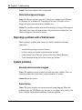
Tools
The VPN Router supports standard IP tools such as ping, Traceroute, and ARP
show and delete. You access these tools through the Admin > Tools window.
The ping command generates an ICMP echo-request message, which any host
can send to test node reachability across a network. The ICMP echo-reply
message indicates that the node is successfully reached.
Nortel VPN Router Troubleshooting
30 Chapter 1 VPN Router administration
The Traceroute tool measures a network round-trip delay. Messages are sent per
hop and the wait occurs between each message. If the address is unreachable, it
uses the following formula to determine how long it takes for the Traceroute to
time out.
maximum hops (30) x the wait timeout (5) x 3 seconds
The Address Resolution Protocol (ARP) dynamically discovers the low-level
physical network hardware address that corresponds to the high-level IP address
for a host. ARP is limited to physical network systems that support broadcast
packets that are heard by all hosts on the network.
System configuration
Use the Admin > Config window to save the current or delete existing system
configuration files. Additionally, you can select one of the previously named
configurations and restore it as the current configuration.
File management
Use the Admin > File System > File System Maintenance window to navigate
through the VPN Router file system. This window lists the devices (drives) and
directories, which provides flexibility in viewing details of a file or directory and
allows you to delete unnecessary files. For example, if you have problems
performing an FTP transfer with a specific file, you can view the file details to
learn its file size and when it was last modified for troubleshooting purposes.
Additionally, you can toggle between hard drives when a backup drive is
available.
NN46110-602
Chapter 1 VPN Router administration 31
Simple Network Management Protocol (SNMP)
Use the Admin > SNMP window to do the following:
•
•
designate the remote SNMP management stations that are authorized to send
SNMP Gets to the VPN Router
enable specific MIBs
Note: A Nortel proprietary MIB is included on the Nortel CD. Click the
CesTraps.mib file to load the MIB. See Appendix A, “MIB support,” for
a description of the CesTraps.mib.
SNMP counters measure packet attributes based on the outer IP header. The inner
IP header does not contribute to the SNMP MIB counters. For example, the outer
packet header can be good and counted, but if the inner packet header is corrupted,
it does not contribute to the drop counter.
You can view the results of SNMP traps on the Health Check window.
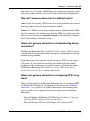
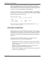
Use the Admin > SNMP Traps window to generate SNMP Version 1 traps, based
on MIB II. From the SNMP Traps window, you can do the following:
•
•
•
designate the remote SNMP trap hosts that can receive traps from the VPN
Router
select the specific traps that you want the SNMP hosts to receive
configure a trap to be sent only once
To enable traps, select one of the following trap groups from the SNMP Traps
window:
•
•
•
•
•
hardware
server
service
standard IETF
attack
Nortel VPN Router Troubleshooting
32 Chapter 1 VPN Router administration
The traps displayed on the group windows—in particular the Hardware Trap
Configuration and the Service Trap Configuration windows—reflect the hardware
and software available on your VPN Router. For example, if you have a VPN
Router with no WAN interface cards, the traps for WAN interfaces do not appear
on the Hardware Trap Configuration window.
Note: The Health Check window reports the results of many of the
selections you make on the SNMP Traps window.
Most of the traps the VPN Router sends to configured trap hosts are also displayed
on the SNMP Traps window. However, the SNMP Traps window does not display
certain traps, including traps related to the status of branch office tunnels, due to
space limitations. For example, when a physical interface status changes, many
traps are sent reporting the failure of all the tunnels using this interface. The VPN
Router sends all traps—whether they appear on the SNMP Traps window—to the
SNMP management application specified as the trap destination.
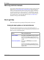
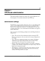
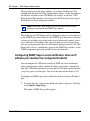
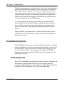
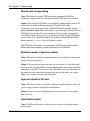
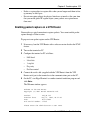
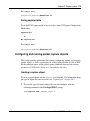
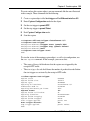
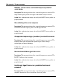
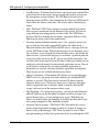
Configuring SNMP traps to send notification when an IP
address pool reaches the configured threshold
You can configure the VPN Router to make an SNMP trap send a notification
about an exhausted pool when a defined IP address pool reaches a configurable
limit. The VPN Router periodically traverses the list of IP address pools and sends
a trap if any pool is over the quota. You can set the limit and the default is 70%.
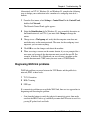
To configure an SNMP trap to send a notification about an exhausted IP address
pool:
1
To capture the traps, you must first define and enable a target host. To do that,
select Admin > Snmp Traps.
The Admin > SNMP Traps window appears.
NN46110-602
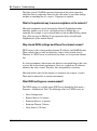
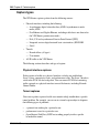
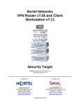
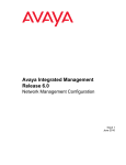
Chapter 1 VPN Router administration 33
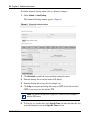
Figure 1
Admin > SNMP Traps window
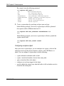
2
Enter a host name or IP address in the Host Name or IP Address text box.
3
Enter a name in the Community Name text box.
4
Click Enable.
5
Click OK.
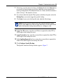
6
Under the Trap Groups section on the SNMP Traps window, click
Configure beside Service.
7
Click OK.
The Service Trap Configuration window appears.
8
Click Enable for User IP Address Pool.
9
Click OK.
The Address Pool window appears.
10 In the Address Pool Exhausted Amount text box, enter the limit of an IP
pool that triggers an SNMP trap. The range is from 50 to 99 and the default is
70.
11 In the Address Pool Blackout Interval, enter in seconds the amount of time
before an address is available for reissue. The default is 10.
12 Click OK.
You can also use the CLI to configure an SNMP trap to send a notification about
an exhausted IP address pool.
To configure the interval:
CES(config)#$enable traps service ip-pool-exhausted interval
<hh:mm:ss> [send-one]
Nortel VPN Router Troubleshooting
34 Chapter 1 VPN Router administration
To configure the amount:
CES(config)#ip local pool exhausted-amount <amount>
NN46110-602
35
Chapter 2
Status and logging
The Status windows show which users are logged on, their traffic demands, and a
summary of the VPN Router’s hardware configuration, including available
memory and disk space.
The status windows include:
•
•
•
•
•
•
Sessions
Reports
System
Health check
Statistics
Accounting
The VPN Router has the following logs that provide different levels of
information:
•
•
•
•
Security log
Config log
System log
Event log
The logs are stored in text files on disk and they indicate what happened, when,
and to which user (IP address and user ID).
The event log captures real-time logging over a relatively short period of time (for
example, the event log can wrap 2000 possible entries in minutes). The system log
captures data over a longer period of time, up to 61 days.
Nortel VPN Router Troubleshooting
36 Chapter 2 Status and logging
Most events are sent to the event log first. Significant events from the event log are
sent to the system log. (Not all data that the system log saves comes from the
event log.) From the system log, the VPN Router filters security entries for the
security log and configuration entries for the configuration log. You can use the
different log options to write specific event levels to the log files and view them,
including:
•
•
•
•
Normal
Urgent
Detailed
All
Sessions
You can monitor which users are tunneled into the VPN Router, when they logged
in, and the number of bytes and packets they transmitted or received. Additionally,
you can see selected session details, and you can log off users.
Once a session is connected, detailed information about the connection is
available from the Status > Sessions window. This window lists all connected
sessions, including administrative sessions. As well as statistics, this information
contains what encryption was negotiated and the SOIs of the security associations.
Click the appropriate buttons beside each session to either log out of the session or
view detailed information about it.
Reports
Use the Status > Reports window to view system and performance data in text or
graphical format. You generate reports in an on-screen tabular format, and you can
import the reports into a spreadsheet or database through the comma-delimited
format.
At midnight (12:00 a.m.), the data collection task performs summary calculations
and rewrites history files, along with other management and cleanup functions. To
perform this task, leave the VPN Router running overnight. The VPN Router must
be running at midnight to generate a historical graph for the day.
NN46110-602
Chapter 2 Status and logging 37
If you have multiple VPN Routers throughout the world, use the Greenwich Mean
Time (GMT) standard to synchronize the various log files so that the timestamps
are directly comparable.
System
The Status > System window shows the VPN Router’s up time, software and
hardware configurations, and the current status of key devices. When there is a
pending shutdown or an Internetwork Packet Exchange (IPX) public network
address change that requires a reboot, the top of this window list these events.
Health check
The Status > Health Check window provides an overall summary of the current
state of the VPN Router’s hardware and software components at a glance. It lists
all aspects of unit operation, with the most critical information to check at the top
of the window. Click the link on the right side of the window to go directly to the
window for configuration of that feature.
Statistics
The Status > Statistics window provides many subwindows with a wealth of
general and diagnostic information about the system hardware, software, and
connections. Much of the information is specifically designed for Nortel
Customer Support personnel to assist them in diagnosing problems. Some
windows, however, such as the LAN Counters, Interfaces, and WAN Status
windows, provide you with traffic information. Use the Status > Statistics window
to see text displays of system-level statistics to resolve lower-level problems with
connections. These displays are similar to command-line output from the
operating system.
In normal operation and routine troubleshooting, it is not necessary to examine
many of these windows. Some of the information, such as routing information, is
also available through other windows, such as System > Routing.
Nortel VPN Router Troubleshooting
38 Chapter 2 Status and logging
Accounting
The accounting log provides information about user sessions. This log provides
last and first names, user ID, tunnel type, session start and end dates, and the
number of packets and bytes transferred. You can use most of these fields to
search the log.
Accounting records
Accounting records are detailed logs that record the various activities performed
by the VPN Router. The logs are directly available from the management
interface and you can export them to other applications for additional processing.
The VPN Router gathers and stores data about the current state of the VPN Router
and the connections. The data is stored in files on the VPN Router’s hard drive.
•
•
Session Status: RADIUS Accounting—the VPN Router stores copies of
RADIUS accounting records. These records, which you can retrieve through
FTP or send to a RADIUS server, contain information about each VPN
session initiated to the VPN Router.
System Data: Data Collection Task—The data collection task runs on the
VPN Router and gathers data about the system’s status. Each minute, the task
captures data and writes it to a data file. You use the information the task
captures to create the graphs and reports available from the Status > Reports
window.
Note: The results of accounting record searches can be incorrect if
another administrator initiates a new search before the first search is
completed. Therefore, ensure that not more than one administrator is
searching accounting records at one time.
NN46110-602
Chapter 2 Status and logging 39
The data collection system stores records in text-based files stored in the system/
dclog subdirectory. The system stores the most recent 60 days of data. The system
stores daily files, summary files, and summary history files. Ongoing
administration tasks include monitoring the configuration files, backing up and
restoring the VPN Router or the LDAP database, and upgrading images and
clients.
Note: The VPN Router does not sort accounting records and displays
them in a random order.
RADIUS accounting
The VPN Router stores copies of RADIUS accounting records and normally
sends these records to a standard RADIUS Accounting server. To configure a
RADIUS accounting server, select Servers > RADIUS Acct.
To view the information in the standard RADIUS accounting records, select
Status > Accounting. The VPN Router creates a file for each day and keeps the
most recent 60 days of data, storing them in the SYSTEM/ACCTLOG directory.
Note: The Status > Accounting window can provide misleading branch
office session information because it displays rekeyed branch office
tunnels as separate entries. The VPN Router does not send RADIUS
accounting records to external servers for branch office connections.
Data collection task
The VPN Router runs the data collection task runs and gathers data about the
system’s status. The task captures data every minute and writes it to a data file.
The VPN Router uses the information this task captures to create the graphs and
reports available from the Status > Reports window and stores this information in
text-based files in the system/dclog directory. The VPN Router creates the
following types of files in the this directory:
•
Daily files that contain interval records gathered every 60 seconds. These
values are interval values and there is a file for each day (for example
20040622.DC).
Nortel VPN Router Troubleshooting
40 Chapter 2 Status and logging
•
•
Summary file that always has exactly five records containing summary data in
a file called summary.dc. These values are used to give historical graphs and
reports about specific values.
Summary history file that contains records representing cumulative daily data
for the most recent 60 days in a file called summs.dc. Each day’s summary is
represented by four records. These records are for the current, total, average,
and maximum values for the day.
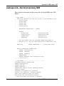
A data collection record consists of 16 pairs of entries for each data collection
object currently being collected. Each value pair consists of a Field ID and an
integer value. The following is a sample data collection record:
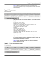
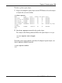
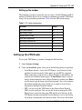
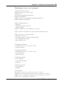
0-930057960,1-3,2-3,3-0,4-0,5-0,6-0,7-0,8-0,9-0,10-56,11-76,12-1,13-11021,1440,15-38,16-0
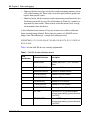
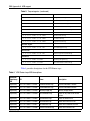
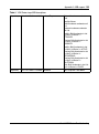
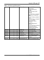
Table 1 lists the field IDs that are currently implemented.
Table 1 Field IDs for data collection records
NN46110-602
Field
identification
Collected field value
Description
0
TIMESTAMP
Seconds since Jan 1, 1970 - 00:00:00
Hours
1
TOTALSESSIONS
Summary of all sessions
2
ADMINSESSIONS
Number of Admin sessions
3
PPTPSESSIONS
Number of PPTP sessions
4
IPSECSESSIONS
Number of IPsec sessions
5
L2FSESSIONS
Number of L2F sessions
6
L2TPSESSIONS
Number of L2TP sessions
7
IPADDRESSUSE
Percentage of total IP addresses in use
8
CPUUSE
Unfiltered CPU usage measurement
{integer representing a percent between
0 and 100}
9
CPUSMOOTH
Filtered CPU usage measurement
{integer representing a percent between
0 and 100}
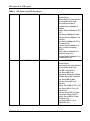
Chapter 2 Status and logging 41
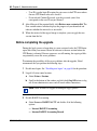
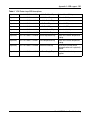
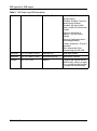
Table 1 Field IDs for data collection records (continued)
Field
identification
Collected field value
Description
10
MEMUSE
Filtered memory usage measurement
{integer representing a percent between
0 and 100}
11
BOXPACKETSIN
Number of Inbound Packets
12
BOXPACKETSOUT
Number of Outbound Packets
13
BOXBYTESIN
Number of Inbound bytes
14
BOXBYTESOUT
Number of Outbound bytes
15
BOXDROPPEDPACK Number of discarded packets
ETS
16
FAILEDAUTHATTE
MPTS
17
LASTFIELDID (this
field is never written to
data record)
Number of failed authentication
attempts
Logs
The VPN Router has several logs that provide different levels of information. The
logs are stored in text files and indicate what happened, when the event occurred,
and the IP address and user ID of the person causing the event.
Event log
The event log is a detailed recording of all events that take place on the system.
These entries are not necessarily written to disk, as with the system log. The event
log retains all system activity in memory, but you must configure the system to
save the event log either automatically or in a specified file.
The event log includes information on tunneling, security, backups, debugging,
hardware, security, daemon processes, software drivers, and interface card driver
events.
Nortel VPN Router Troubleshooting
42 Chapter 2 Status and logging
As the event log adds information, the oldest entries are overwritten. The event log
retains the latest 2000 entries and discards old entries when it is refreshed.
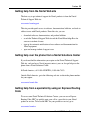
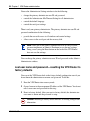
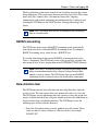
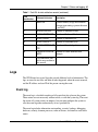
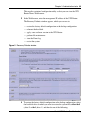
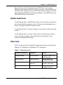
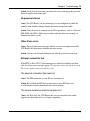
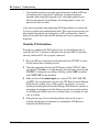
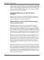
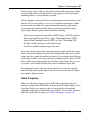
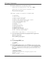
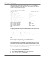
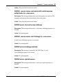
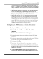
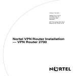
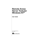
To configure event logging:
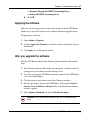
1
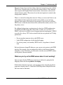
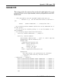
Select Status > Event Log.
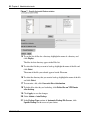
The Event Log window appears. (Figure 2)
Figure 2 Event logs
NN46110-602
2
In the Save Events to section, enter a filename and click Save to manually
save the current event log at any time.
3
In the Auto Save Events to section, select the maximum number of files that
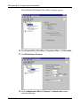
you want to save and click Enabled to automatically save the event log.
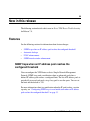
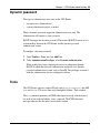
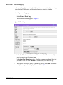
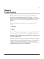
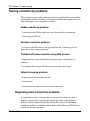
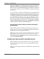
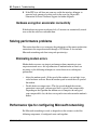
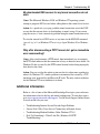
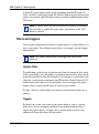
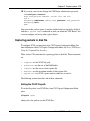
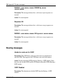
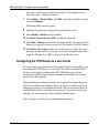
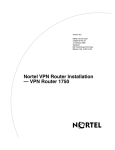
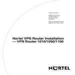
4
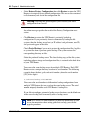
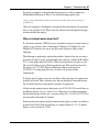
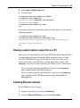
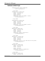
The Capture and Display filters are hidden by default. Click Show to view or
configure the capture and display filter capabilities. (Figure 3)
Chapter 2 Status and logging 43
Figure 3 Capture and display filters
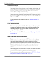
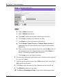
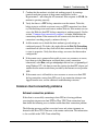
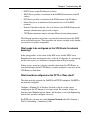
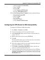
5
You configure the capture filter and display filter using Entity-Subentity or
Severity. To configure the capture filter or display filter:
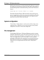
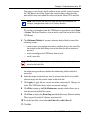
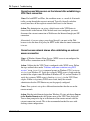
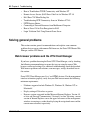
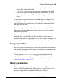
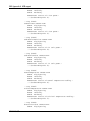
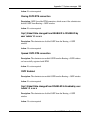
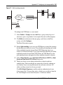
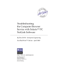
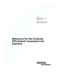
a
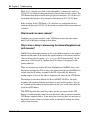
Click Configure Capture Entity or Configure Display Entity. Figure 4
shows the Configure Display Entity window.
Nortel VPN Router Troubleshooting
44 Chapter 2 Status and logging
Figure 4 Configure Display Entity
b
Select an Entity from the list.
c
Select a Subentity from the list.
d
Click Add to add the selected entity-subentity pair to the filter.
e
Click Accept to complete your changes to the filter.
f
Click Remove to delete a selected item from the list.
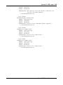
g
Click Configure Capture Severity or Configure Display Severity to
configure the level of severity that you want to display on the window
from the log.
h
Select a severity message from the Severity list and click Add to add it to
the Captured Severity list or Displayed Severity list. Select Remove to
remove a selected item currently in the Severity list.
i
Click Accept to save any changes you make.
6
To sort the log based on key word matches, enter a list of key words, separated
by a space or a comma.
7
Select the type of match you want. Select AND to match all key words. Select
OR to match any key words.
8
Click Clear to clear the entire log. Only Administrators can clear the log.
9
Click Refresh to display new log entries.
10 Click Reverse Chronological Order to log in reverse chronological order.
NN46110-602
Chapter 2 Status and logging 45
System log
The system log contains all system events that are considered significant enough
to be written to disk, including those displayed in the configuration and security
logs. Events that appear in the system log include:
•
•
•
LDAP activity
configuration activity
server authentication and authorization requests
The following is the general format of the log entries:
•
•
•
•
•
•
•
time stamp
task that issued the event (tEvtLgMgr, tObjMgr, tHttpdTask)
number that indicates the CPU that issued the event (0=CPU 0, 1=CPU 1)
software module that issued the event
priority code assignment (number in brackets) (for a description of these
codes, see “Event log” on page 41)
indicates that the packet matched the rule in the listed section
indicates the matching packet source, destination, protocol, and action
configured for that rule
The following example shows a system log:
11:29:31 tEvtLgMgr 0 : CSFW [12] Rule[OVERRIDE 1]Firewall:
[192.32.250.204:1024-10.0.18.12:2048, icmp], action: Allow
Security log
The Security log records all activity about system or user security. It lists all
security events, both failures and successes. The events can include:
•
•
•
•
•
authentication and authorization
tunnel or administration requests
encryption, authentication, or compression
hours of access
number of session violations
Nortel VPN Router Troubleshooting
46 Chapter 2 Status and logging
•
•
•
communications with servers
LDAP
Remote Authentication Dial-In User Service (RADIUS)
Configuration log
The Configuration log records all configuration changes. For example, it tracks
adding, modifying, or deleting the following configuration parameters:
•
•
•
•
•
•
NN46110-602
group or user profiles
LAN or wide area network (WAN) interfaces
filters
system access hours
shutdown or startup policies
file maintenance or backup policies
47
Chapter 3
Administrative tasks
This chapter describes administrative tasks that help you operate the VPN Router.
These tasks provide details on scheduling backups, upgrading the software image,
saving configuration files, performing file maintenance, creating recovery
diskettes, and system shutdown.
Shutdown
You use the Shutdown options to shut down immediately, to wait until current
users are logged off, or to wait until a designated time. A normal shutdown safely
terminates connections so that no data is lost, compared with a spontaneous loss
of power.
Additionally, you can select whether to power off or restart after shutdown and
which configuration file to use upon restarting. To conduct an orderly shutdown,
you can disable new logins, and you can disable logins after the shutdown to
perform system maintenance.
Always use the Admin > Shutdown window to shut down the system rather than
the Power or Reset buttons on the back of the VPN Router. This ensures the
integrity of your file system.
Note: After performing a system shutdown, click Reload/Refresh to
see the latest VPN Router information.
Nortel VPN Router Troubleshooting
48 Chapter 3 Administrative tasks
Recovery
In the unlikely event that there is a hard disk crash, use the Recovery window to
configure a recovery diskette to restore the software image and file system to the
hard drive of the VPN Router. The recovery diskette is included with your VPN
Router. You can also use this window to create additional copies of the recovery
diskette, as well as to reformat a diskette.
Note: The VPN Router 1000, 1010, 1050, and 1100 do not have a
floppy drive in the unit. Although the VPN Router 600 does not have a
floppy drive, the recovery image is stored in a PROM and you can
invoke it by pressing a switch on the back of the unit.
Accessing the diskette drive
If the VPN Router has a front cover, you must remove it to gain access to the
diskette drive. See the installation guide for details on how to remove the front
cover. Booting the VPN Router with the recovery diskette does the following:
•
•
•
•
reformats the hard disk
allows FTP access to the hard disk
restores the previously backed-up software image and file system from a
backup host to the hard disk
downloads a new factory default software image and file system from a file
server to the hard disk
These utilities are accessed throught Hypertext Transfer Protocol (HTTP) after it
is booted from the recovery diskette.
Using the recovery diskette
To use the recovery diskette:
NN46110-602
1
Remove the VPN Router’s front cover.
2
Insert the recovery diskette into the drive and press Reset on the back of the
VPN Router.
Chapter 3 Administrative tasks 49
This supplies a minimal configuration utility so that you can view the VPN
Router from a Web browser.
3
In the Web browser, enter the management IP address of the VPN Router.
The Recovery Diskette window appears, which you can use to:
—
—
—
—
—
—
restore the factory default configuration or the backup configuration
reformat the hard disk
apply a new software version to the VPN Router
perform file maintenance
view the Event log
restart the system
Figure 5 Recovery Diskette window
4
To restore the factory default configuration or the backup configuration, select
the hard disk drive to which you want to restore the system files, either ide0
(drive 0) or ide1 (drive 1), and then do one of the following:
Nortel VPN Router Troubleshooting
50 Chapter 3 Administrative tasks
•
Select Restore Factory Configuration, then click Restore to return the VPN
Router to its original factory default configuration. This erases data contained
in flash memory and also in the configuration file.
Warning: Selecting this option requires you to rebuild your entire
configuration from scratch.
An online message specifies the result of the Factory Configuration reset
action.
•
Click Restore to restore the VPN Router’s previously backed-up
configuration. If you previously chose to automatically backup the file
systems, then the backup server host (or IP address) and path name, user ID,
and password appear in the table.
Check Partial Backup if you want to restore the configuration files, log files
or system files from a previous partial backup. The system restores the
corresponding directory or files.
Select the preferred backup server. The latest backup copy of the file system,
including software image and configuration files, is restored to the hard drive
of your VPN Router.
You can use the same backup server for multiple VPN Routers. Each VPN
Router creates a unique directory based on its serial number. The following
example shows the host, path, and serial number (where the serial number
[SN] is five digits):
C:/software/backup/v101/SN01001
You can use the serial number to differentiate backup configurations from
multiple VPN Routers that are saved on the same backup server. The serial
number uniquely identifies each VPN Router’s backup data.
If you did not configure automatic backup server locations, use the blank row
in the server backup field to manually enter a backup server.
Note: FTP servers are often different, so check for information in your
server documentation about setting paths that can help you with the
upgrade procedure.
NN46110-602
Chapter 3 Administrative tasks 51
You can use a new factory default software image and file system to restore
the VPN Router’s hard disk. Specify the name or address and path of the
network file server onto which the software from the Nortel CD is installed.
Note: This restores the disk to an operable but clean condition (for
example, configuration values are at factory defaults).
To view the serial number when the VPN Router is operational, select Status
> System. The Serial Number is also on the bar code label on the back of the
VPN Router.
5
Click Reformat Diskette if you must reformat the hard disk for one of the
following reasons:
— cannot restore your configuration due to problems that are not caused by
the network or the file/backup server from which the file restoration is
retrieved
— want to reconfigure the VPN Router from scratch
— install a new disk
Caution: Selecting this option completely wipes out anything that was
stored on the hard disk.
An online message indicates whether the reformatting of the hard disk is
successful.
6
Select the image version that you want to activate from the list of available
software image and file systems stored on the hard disk.
7
Click Apply to apply the new version and reboot automatically. Changes are
active. The VPN Router boots to that version until changed.
8
Click Files to bring up the File Maintenance window, which allows you to
view the entire hard disk file system.
9
Click View to display the Event Log beneath the Recovery Diskette window.
This is especially useful if a Restore operation fails.
10 To set the boot disk, select either ide0 (drive 0) or ide1 (drive 1).
11 Click Set.
Nortel VPN Router Troubleshooting
52 Chapter 3 Administrative tasks
12 Click Synchronize to immediately synchronize the primary and secondary
disks. Thereafter, the disks automatically synchronize every hour.
13 From the list, select the drive on which you want to upgrade the system boot
software.
14 If the system boot sector is corrupted, click Upgrade to rewrite the boot
software to the hard disk.
15 To restart the system, remove the diskette and press Reset on the back of the
VPN Router. Reposition your Web browser to the Management IP address,
and select Reload or Refresh from your browser menu to access the
management window of the software running on the hard disk.
Note: You cannot use this procedure for the VPN Router 1000 due to
the lack of a floppy drive in the unit. Although the VPN Router 600 does
not have a floppy drive, the recovery image is stored in a PROM; you
can invoke it by pressing a switch on the back of the unit.
Automatic backups
The VPN Router checks at regular intervals to see whether there are any system
file changes. When system file changes occur, they are written to each of the
backup servers. The VPN Router backs up all of the system files the first time;
thereafter, it backs up only the files that change.
Note: Any changes made to backup parameters while a backup is in
process do not take effect until the currently running backup is complete.
The VPN Router does not begin a backup for at least 5 minutes after rebooting to
allow all resources to start operating. This delay occurs even if you request that a
backup start immediately. Use the Admin > Auto backup window to configure
regular intervals or specific times when your system files are saved to designated
host backup file servers. You can designate up to three backup file servers.
NN46110-602
Chapter 3 Administrative tasks 53
You must create a directory on the File Transfer Protocol (FTP) or Secure File
Transfer Protocol (SFTP) server before running automatic backup. If you specify
a path in the Admin > Auto backup window and the directory does not exist on the
FTP or SFTP server, the automatic backup fails and The host path does not exist
message is logged in the Event log.
Note: Automatic backup does not recognize a path beginning with the
slash (/) character as it did in previous releases.
Using the GUI for automatic backup
You can use the CLI to transfer backup files through SFTP or to trigger a backup
when a file or directory changes.
Transferring backup files through SFTP
You can now use an SFTP client to transfer backup files. Previously, you could
use only FTP.
Note: To transfer backup files using SFTP, you must first configure a
remote Secure Shell (SSH) server.
To transfer backup files using sftp:
1
Select Admin > Auto Backup.
2
In the Automatic Backup File Servers section, click the sftp check box for a
particular server. FTP is the default.
Triggering a backup when a file or directory changes
You can trigger an automatic backup when a new file is created in a particular
directory, or when a file or a directory changes. The VPN Router checks at regular
intervals to see whether changes occur. These changes are written only to the
backup server you specify. You can optionally delete that file after the backup is
complete.
Nortel VPN Router Troubleshooting
54 Chapter 3 Administrative tasks
To enable automatic backup when a file or a directory changes:
1
Select Admin > Auto Backup.
The Automatic Backup window appears. (Figure 6)
Figure 6 Automatic backup window
2
Click Enabled to enable the associated host backup file server.
3
Enter the backup file server host name or IP address.
4
Enter the backup file server path, for example, test.
5
Click sftp to transport the backup files using an SFTP client. Do not select
SFTP if you want to use the default, FTP.
Note: To transfer backup files using SFTP, you must first configure a
remote SSH server.
6
NN46110-602
To back up at a specific time, click Specific Time and enter the time that you
want the backup to occur in the Specific Time text box.
Chapter 3 Administrative tasks 55
7
To back up at certain intervals of time, click Interval and in the Interval text
box specify in hours the time period after which the system automatically
backs up changed files. The minimum interval is 1 hour, and the maximum is
8064 (336 days). The default is 5 hours.
8
If you chose either the Specific Time option or the Interval option, select the
Backup Days you want to trigger the specific backup.
9
Click Auto if you want to back up files only when the files change.
Note: Because the auto trigger works only with the Specific backup
option, select auto if you want to trigger the backup of a file found in the
path of the Specific backup whenever there is a change in a file.
10 In the User ID text box, enter the user ID that is required for either FTP or
SFTP logon to the backup file server.
11 In the Password text box, enter the password that is required for either FTP or
SFTP logon to the backup file server.
12 In the Confirm Password text box, reenter the password that is required for
either FTP or SFTP logon to the backup file server.
13 Click Configure Specific Backup.
The Specific Automatic Backup window appears. (Figure 7)
Nortel VPN Router Troubleshooting
56 Chapter 3 Administrative tasks
Figure 7 Specific Automatic Backup window
14 To see the list of files for a directory, highlight the name of a directory and
click Display.
The files for that directory appear in the Files list.
15 To select the file that you want to back up, highlight the name of the file and
click Select.
The name of the file you selected appears beside File name.
16 To select the directory that you want to back up, highlight the name of the file
and click Select.
17 To overwrite a file, click Overwrite files at destination.
18 To delete files after they are backed up, click Delete files on VPN Router
after backup.
19 Click Apply to save the changes.
20 Select Admin > Auto Backup.
21 In the Backup Types section of Automatic Backup File Servers, click
Specific Backup for the server of your choice.
NN46110-602
Chapter 3 Administrative tasks 57
22 Click Backup to run the backup to each enabled server now. This action also
synchronizes the hard disk drives when there is more than one hard drive in a
device. Otherwise, the hard disks synchronize automatically every 60
minutes.
A new window appears with the backup information at the top of the window.
23 Click OK.
After entering the automatic backup file server information, click on the window
and press the keys Alt and Print Scrn (Screen) to save the screen image to a
buffer. Next, paste the image into a file (for example, into Microsoft* Word) and
keep it as a record of the backup file servers that you are using.
Using the CLI for automatic backup
Version 7.00 provides CLI commands for backing up a list of files and directories,
or directories, that changed on the VPN Router. The CLI command exception
backup includes the following parameters:
•
•
•
•
•
•
specific—backs
up specific files or directories only
file-path—backs up additional files or directories in a particular file path
auto—backs up the changes only to any file in a file path
overwrite—overwrites existing files on the host
delete—deletes files on the VPN Router after backup
sftp—uses SFTP to transfer the backup files
For more information about the command parameters, see Nortel VPN Router
Using the Command Line Interface.
Note: To transfer backup files using SFTP, you must first configure a
remote SSH server.
The following sections describe how to use the CLI commands. You must enter
the commands from CLI Global Configuration Mode. For more information about
the Global Configuration Mode, see Nortel VPN Router Using the Command Line
Interface.
Nortel VPN Router Troubleshooting
58 Chapter 3 Administrative tasks
Backing up specific files and directories
To back up specific files and directories, with the option to delete them after
backup, enter:
exception backup advanced {1 | 2 | 3} {full | partial | specific
[<file-path> ] [overwrite] [delete]}
For example, to set the target of the exception backup to a directory /ideX/system/
log, enter:
CES(config)# exception backup advanced 1 specific /ideX/system/log/
overwrite
Stopping the backup of specific files and directories
To stop the backup of specific files and directories, enter:
no exception backup advanced {1 | 2 | 3} {full | partial |specific
[overwrite] [delete]}
For example, to stop the previous exception backup, enter:
CES(config)# no exception backup advanced 1 specific
Backing up changes to specific files or directories
To back up the changes for specific files or directories on a particular server, use
the auto option. The auto option works only with the specific backup type. Enter:
exception backup {1 | 2 | 3} {<ip-address> | <host-name>}
[<file-path>] auto username <user-name> password <password>
For example, to back up the files that changed on backup server number 1, enter:
CES(config)# exception backup 1 10.2.5.68 auto username admin
password setup
NN46110-602
Chapter 3 Administrative tasks 59
Stopping the backup of changes to specific files or directories
To stop backing up the changes for specific files or directories for a particular
server, enter:
no exception backup advanced {1 | 2 | 3} specific
For example, to stop backing up files that changed in backup server number 1,
enter:
CES(config)# no exception backup advanced 1 specific
Using SFTP to transfer backup files
To use SFTP to transfer the backup files, from CLI Global Configuration Mode,
enter:
CES(config)# exception backup {1 | 2 | 3} sftp
For example, to use SFTP to back up the files that changed in backup server
number 2, enter:
CES(config)# exception backup 2 sftp
Stopping the transfer of backup files using SFTP
To use SFTP to stop the backup of files, from CLI Global Configuration Mode,
enter:
CES(config)# no exception backup {1 | 2 | 3} sftp
For example, to use SFTP to stop the transfer of files that changed in backup
server number 2, enter:
CES(config)# no exception backup 2 sftp
For more information about the command parameters, see Nortel VPN Router
Using the Command Line Interface.
Nortel VPN Router Troubleshooting
60 Chapter 3 Administrative tasks
Disabling new logins
You can prevent clients from connecting to the VPN Router without affecting the
users currently connected by using this feature to disable new logins. When new
logins is disabled, no new IPsec connections are established.
To disable new logins:
1
Select Admin > Shutdown.
2
Click Disable new logins. (Figure 8)
Figure 8 Disable new logins
If you do not want to reboot the switch after you disable new logins, click
None in the System Shutdown section.
To disable new logins using the CLI, enter the following command:
CES# reload [at <hh:mm>] [boot-drive] [boot-normal | boot-safe]
[config-file] [power-off | restart] disable-logins
Upgrading the software
To upgrade the VPN Router, download the latest Nortel software using the File
Transfer Protocol (FTP). Because FTP servers are often different, check your
server documentation for information about setting paths that can help you with
the upgrade procedure.
You can download the latest software from:
NN46110-602
Chapter 3 Administrative tasks 61
•
•
•
Nortel Web site
your own FTP site if you previously downloaded the software from the Nortel
FTP site
Nortel software CD
If an FTP server does not use standard FTP port numbers, you cannot use it to
download FTP servers for Nortel software. For more information, contact Nortel
Customer support.
Note: You cannot upgrade the software through a branch office tunnel
that is translating the management address with dynamic Network
Address Translation (NAT).
If file retrieval fails, the VPN Router retries the transfer. The WU-FTP server does
not support this behavior and can cause the negotiation to fail. Explore
connectivity issues as the first possible level of failure.
Checking available disk space
Nortel recommends that you keep a maximum of four software versions on the
system disk. If four versions already exist on the Admin > Upgrade window, you
must delete one version before you download another version.
To remove a software version:
1
Select Admin > File System.
2
Select the Hard Drive (/ide0/).
3
Click Display.
A list of the versions on the VPN Router appears.
4
Click the version you want to view and click Details. When the window
refreshes, you see the directory that you just selected. Click Delete Directory.
A new window appears verifying this is what you intended to do. If there is
more then one image on the hard drive, follow the above process to delete all
the older image upgrades.
Nortel VPN Router Troubleshooting
62 Chapter 3 Administrative tasks
Before you upgrade your software, use one of the following methods to make sure
there is enough available disk space:
•
•
From the GUI, select Status > Statistics > File System. The last line lists the
free space on the disk.
From the CLI, enter show status statistics system file-system. The last line
lists the free space on the disk.
Note: Some restrictions apply if you have a VPN Router 1010, 1050, or
1100. To export the configuration and LDIF files from the device, FTP
the files to a server and view the file size. If the combined size of the
LDIF and configuration files is less than 1Mbyte, you can upgrade to the
latest version. The VPN Router 1010, 1050, and 1100 allow a maximum
of two images on the flash disk. You must remove the second image (if
present) prior to downloading an upgrade.
Creating a control tunnel to upgrade from a remote location
To upgrade the software on a VPN Router from a remote location, you must
create a user control tunnel at the physical location of the VPN Router. User
control tunnels provide secure access to a remote VPN Router so that you can
manage it over a network.
You can create a user control tunnel through the serial port on the VPN Router or
with the GUI. When you create a user under the group Control Tunnels, it
automatically becomes a control tunnel user. To create a user control tunnel
through the serial port:
1
Connect the serial cable (supplied with the VPN Router) from the VPN
Router’s serial port to a terminal or to the communications port on a PC.
2
Turn on the PC or the terminal.
3
On the PC, start HyperTerminal* or another terminal emulation program and
press Enter.
The Welcome window appears.
4
Enter the VPN Router administrator user name and then the password.
The serial main menu appears.
NN46110-602
Chapter 3 Administrative tasks 63
5
Type 5 (Create A User Control Tunnel (IPsec) Profile).
6
Enter the user ID that you plan to use to log in remotely to the VPN Router.
7
Enter the password that you plan to use.
8
Enter the password again.
9
When you are prompted for an IP address, you can enter a static IP address
that is assigned to the user during the control tunnel connection. If an address
pool is configured, you do not need to enter a static IP address.
Go to the next section, “Creating a recovery diskette” on page 63.
Creating a recovery diskette
Before you upgrade the VPN Router, create a recovery diskette. You must
perform this task on the VPN Router itself. To create a recovery diskette:
1
Insert a blank diskette into the floppy drive.
2
Select Admin > Recovery and click Create Diskette.
Note: If you have a diskless system, for example, a VPN Router 1100,
the recovery image is stored in flash memory.
Backing up system files
Before you upgrade, verify that a recent automatic backup was done in one of the
following methods:
1
If you are located at a remote site, connect to the VPN Router through a tunnel
(branch office or user control).
2
Select Admin > Auto Backup and ensure that a recent automatic backup was
performed to an FTP server.
3
If a recent backup does not exist, use the following steps to create the backup
on the Automatic Backup window:
a
Enter an IP address or host name, path, interval, FTP user ID, and
password.
Nortel VPN Router Troubleshooting
64 Chapter 3 Administrative tasks
b
Click Backup to start the backup immediately.
This saves your entire hard drive, including the LDAP and configuration files.
Retrieving the new software
For Version 4.80 and later, the VPN Router release image is available in a
compressed .zip file so that each individual file does not download separately. The
VPN Router decompresses the image as it retrieves it. You must then apply the
new image.
To use the compressed zip file:
1
Place the zip file (for example, V04_80.114.tar.gz) on the FTP server that you
are using for the upgrade.
D:\ftp>dir
Volume in drive D has no label.
Volume Serial Number is 9B29-6769
Directory of D:\ftp
06/18/2003 01:20p
<DIR>
.
06/18/2003 01:20p
<DIR>
..
06/18/2003 06:53a
31,779,808 V04_80.069.tar.gz
Note: Do not attempt to create your own zip archive. Use the .tar.gz file
distributed by Nortel.
2
Select Admin > Upgrades.
3
Fill in the following fields on the Upgrades window:
•
•
•
NN46110-602
Host: type the IP address or the name of the machine where the new
software is located.
Path: type the directory path location of the new software. The path value
is the relative location of the .gz file from the FTP root in the directory. In
the example below, the V04_80.069.tar.gz file is located at the root of the
FTP directory.
Version: type the exact name of the code that you are upgrading to (for
example, V04_80.114).
Chapter 3 Administrative tasks 65
Figure 9 shows an example upgrade to V04_80.114 from server
192.32.250.64. The file V04_80.114.tar.gz must be located at the root of
the FTP directory.
Figure 9 FTP menu example
When you FTP to the FTP server from another PC, you see the location of
the file.
D:\ftp>ftp 192.32.250.64
Connected to 192.32.250.64.
220 entrust-ca Microsoft FTP Service (Version 2.0).
User (192.32.250.64:(none)): anon
331 Password required for anon.
Password:
230 User anon logged in.
ftp> ls V04_80.069.tar.gz
200 PORT command successful.
150 Opening ASCII mode data connection for file list.
V04_80.069.tar.gz
226 Transfer complete.
ftp: 19 bytes received in 0.62Seconds 0.03Kbytes/sec.
ftp>
If you want to locate the tar file in a subdirectory on the FTP server, you
must prepend the subdirectory to the path.
Figure 10 shows an example with the tar file located in the images
directory under the FTP root.
Figure 10 FTP menu with subdirectory example
Nortel VPN Router Troubleshooting
66 Chapter 3 Administrative tasks
•
•
User ID: type the login ID required to gain access to the FTP server where
the new VPN Router software is located.
Password and Confirm Password: type the password (twice) that
corresponds to the user ID you just entered.
4
After filling in all the required fields, click Retrieve new version to disk. The
New version retrieval window displays the progress of your download and
indicates whether the retrieval was successful.
5
When the retrieval of the zipped image is complete, you can apply the new
version from the list.
Before completing the upgrade
During the Apply process of upgrading to a new version of code, the VPN Router
copies files from your current version of software to the new version before the
VPN Router is rebooted. Because processes are still running, the copying of files
can potentially cause file access problems.
To minimize the possibility of file access problems after the upgrade, Nortel
recommends that you perform the following steps.
1
Disable new logins. See “Disabling new logins” on page 60 for the procedure.
2
Log off all active tunnel sessions.
a
Select Status > Sessions.
b
Scroll to the bottom of the window and click both Log Off buttons to log
off all non-administrative users and all branch office connections.
Note: These sessions are logged off during the Apply process
3
Disable RADIUS accounting.
a
Select Servers > RADIUS ACCT and disable all of the following
options:
— Internal RADIUS Accounting
— Interim RADIUS Accounting Record
NN46110-602
Chapter 3 Administrative tasks 67
— Response Timeout for RADIUS Accounting Server
— External RADIUS Accounting Server
b
Click OK.
Applying the software
After you start the apply process, do not make any queries on the VPN Router.
Queries try to access files and can cause problems during the upgrade process.
To apply the new software:
1
Select Admin > Upgrades.
2
From the Apply New Version list, select the software version that you just
downloaded.
3
Click Apply to start the upgrade process.
After you upgrade the software
After the VPN Router reboots itself with the upgraded software, follow these
steps:
1
Wait 2 minutes after the reboot before you run queries to make sure that all
startup processes had time to read the files they need.
2
If you are managing the VPN Router remotely, connect to the VPN Router
over a user control tunnel.
3
Clear the cache on your browser and close all browser windows.
4
Restart your browser, log on to the VPN Router, and navigate to Status >
System. Check the Software Version field to verify that the new software
version is applied.
5
Select Admin > Shutdown and deselect Disable new logins.
Caution: If you do not follow the next step, the VPN Router shuts
down.
Nortel VPN Router Troubleshooting
68 Chapter 3 Administrative tasks
6
Select a system shutdown type of None and click OK.
You have successfully upgraded your switch.
NN46110-602
69
Chapter 4
Troubleshooting
This chapter introduces the concepts and practices of advanced network
configuration and troubleshooting for the Nortel VPN Router. Its purpose is
two-fold: to provide configuration details to consult when setting up or modifying
the extranet, and to serve as a resource when diagnosing client and network
problems.
Typically, there are three types of problems to address when managing an
extranet:
•
•
•
connectivity
performance
general
As a network administrator, your primary concern is to maintain connectivity. For
extranet access, this means maintaining the secure connections between your
remote users and the private intranet serviced by the VPN Router. Performance is
another area of concern. Paying attention to performance helps you address issues
before they become problems.
Connectivity problems occur when the remote user cannot establish a connection
with areas of their private corporate network. There are several points of failure to
consider when diagnosing connectivity problems. Problems can range from
something as simple as a modem configuration error on the client workstation to a
complex HDLC protocol error on the T1 WAN interface.
Nortel VPN Router Troubleshooting
70 Chapter 4 Troubleshooting
Troubleshooting remote access problems typically starts at the client end when the
remote user cannot establish a connection, loses a connection, or has difficulty
browsing the network or printing. When connectivity problems occur and the
source of the problem is unknown, it is usually best to follow the OSI network
architecture layers. Therefore, start diagnosing the physical environment, the
modem, and the cables before moving up to the network and application layers
(for example, pinging a host and Web browsing).
As with connectivity, there are many places in the extranet network where
network performance is affected. By regularly checking the network statistics,
logs, and health check information, and by informing users of good network
practices, you can often avoid problems and enhance the productivity of the
extranet.
General problems are categorized here as problems other than those related to
connectivity or network performance. For the latest release-specific problems,
check the release notes.
Troubleshooting tools
For the VPN Router administrator, a robust troubleshooting toolbox is filled with
both standard and special tools for diagnosing network problems. Standard tools
like Telnet, PING, Trace Route (tracert.exe), sniffers, and analyzers are a basic
necessity. To this collection, some special tools are added to the VPN Router
manager and remote client applications. These special tools include client- and
VPN Router-based tools.
Client-based tools
IPsec VPN Client Monitor provides network statistics on device, connection, and
network errors that help monitor traffic flow and assess IPsec connection
performance. Statistic counters are updated once a second. For more information
on the IPsec VPN Client Monitor, see the VPN Client online Help.
NN46110-602
Chapter 4 Troubleshooting 71
Microsoft Point-to-Point Tunneling Protocol (PPTP) Dial-Up Networking
Monitor provides network statistics on device, connection, and network protocols
that help monitor traffic flow and assess PPTP connection performance. For more
information on the PPTP Dial-Up Networking Monitor, see the PPTP help or your
Microsoft PPTP client documentation.
System-based tools
Use the Manager Status > Health Check window to view colored status indicators
that evaluate individual component status, and click associated hyperlinks to go
directly to manager windows for corrective action.
Use the Manager Status > Statistics window to view detailed system and network
statistics.
Use the Manager Status > Security, Config, System, and Event Log window to
view various logs recording system and network events that help you trace
problems and determine their origins.
Other tools
Table 2 lists the tools that are helpful for diagnosing connectivity problems from
Windows* 95, Windows 98, and Windows NT* workstations.
Table 2 Troubleshooting tools
Windows 95/Windows 98
Windows NT
Use for...
Winipcfg command
Ipconfig command
Obtaining IP address, DNS,
WINS information
Netstat command
Netstats command
Viewing statistics from
Microsoft TCP/IP stack
Ping and tracert commands
Ping and tracert
commands
Testing connectivity, name
resolution, route tracing
Dial-Up Monitor status
Dial-Up Monitor status
Viewing modem settings,
throughput and errors
Nortel VPN Router Troubleshooting
72 Chapter 4 Troubleshooting
Solving connectivity problems
This section lists many of the common connectivity problems that occur and their
recommended solutions. Problems, and some typical client user responses that can
help with diagnosis, are categorized as follows:
Modem and dial-up problems
“I cannot browse the Web or check my e-mail over my dial-up connection.”
“I cannot ping my ISP site.”
Extranet connection problems
“I can browse the Web over my dial-up connection, but I cannot log in to my
network over the extranet connection.”
Problems with name resolution using DNS services
“I logged into my corporate network, but I get messages saying the host is
unknown.”
“I can ping the host using its IP address, but not using its host name.”
Network browsing problems
“I cannot browse the corporate network.”
“I cannot print.”
“I cannot access the Internet over my extranet connection.”
Diagnosing client connectivity problems
A connection can fail at varying points in an extranet. If remote users have a
problem accessing their corporate network and the source of the problem is
unknown, Nortel recommends that they follow these steps to first determine
whether the problem is with their modem, Point-to-Point Protocol (PPP) dial-up,
or with the extranet connection:
NN46110-602
Chapter 4 Troubleshooting 73
1
Confirm that the modem is attached and working properly by running a
terminal emulation program at their remote workstation, such as,
Hyperterminal*, and issuing the AT command. If the response is AT OK, the
modem is operating correctly.
2
Verify that there is a PPP dial-up connection over the internet. To do this,
before trying to establish an extranet access or PPTP connection, have them
try Web browsing www.nortel.com or another Web site. If the remote user can
access the Web site, their PPP dial-up connection is working properly. See the
section "Common client connectivity problems" to further troubleshoot the
connection problem. If the remote user still cannot verify that their dial-up
connection is working properly, continue with step 3.
3
Ask the remote user to check that their modem type and settings are
configured properly. To do this, they right-click on the Dial-Up Networking
connection icon (the icon they click to dial their connection) on their desktop
to view its properties. Verify that these settings are correct for their modem
configuration.
4
If the remote user is connected but unable to access any resources or servers,
have them go to the Start menu and check their system's connection
information, select Run, and type winipcfg in the text box (or ipconfig if
using Windows NT). Ask them to view the statistics for their PPP adapter and
confirm that the entries match those provided by the Internet service provider
(ISP).
5
If the remote user is still unable to view resources or servers over their PPP
dial-up connection, contact their ISP to see if any connection attempts were
logged from the user, and for additional troubleshooting assistance.
Common client connectivity problems
Extranet connection problems
If the client is successfully connecting to their ISP, but is having problems
accessing their intranet over their PPTP or IPsec VPN Client connection, have
them check the following areas to further troubleshoot their connection problem.
The following messages and their associated cause and action statements are
directed to the IPsec VPN Client user at the remote workstation. This information
is also available in the VPN Client online Help.
Nortel VPN Router Troubleshooting
74 Chapter 4 Troubleshooting
Remote host not responding
Cause: This indicates that the VPN Router never responded to the IPsec
connection attempt or that User Datagram Protocol (UDP) port 500 is blocked.
Action: Verify that the VPN Router is accessible by pinging the host name or IP
address that you filled in the destination field. To ping a host called
extranet.corp.com, for example, open an MS-DOS command prompt and type
ping extranet.corp.com. If you receive a reply message, it indicates that the
VPN Router is accessible but is not responding. If you received a message that
says Request Timed Out from the ping command, it means that the VPN Router
is inaccessible. You can further diagnose the problem using the MS-DOS Trace
Route command (tracert.exe) on Windows systems.
The VPN Router allows only a certain number of PING packets from another
Internet host before requiring a tunnel connection to be established.
Maximum number of sessions reached
Cause: This indicates that the maximum number of users for the account you are
using are currently logged in.
Action: If you are the only user with access to your account, it is possible to get
this error if you restarted an IPsec connection immediately after losing the dial-up
connection to your ISP. This is because the VPN Router takes up to one minute to
determine that your connection is dropped and logs you off from your account.
Simply wait a minute and retry your connection.
Login not allowed at this time
Cause: This indicates that your account is limited to specific hours of access and
you are trying to connect outside of the allowed time.
Action: Contact your network administrator if you are unsure of your specific
hours of access.
Authentication failed
Cause: The IPsec user name is incorrect or the password is invalid for the user
name entered.
NN46110-602
Chapter 4 Troubleshooting 75
Action: Verify that the user name you entered is correct and retype the password
before trying the connection again.
No proposal chosen
Cause: The VPN Router you are connecting to is not configured to handle the
authentication method configured under the current connection profile.
Action: Verify that you are using the correct IPsec parameters, such as a choice of
ESP-3DES with SHA1. Make sure it matches what the client (for example, an
International client) can do.
Other IPsec errors
Cause: Typically other error messages indicate an error in configuration on the
VPN Router that the network administrator must correct.
Action: Contact your Network Administrator with the specific error message.
Extranet connection lost
If the PPTP or IPsec VPN Client connection was initially established and then
fails, one of two error messages appear: The physical connection has been lost or
The secure extranet connection has been lost.
The physical connection has been lost
Cause: The PPP connection to your ISP was disconnected.
Action: Re-establish the PPP dial-up connection to your ISP before you
re-establish the extranet connection to the remote network.
The secure extranet connection has been lost
Cause: For IPsec only, the VPN Router that you are connected to has either
logged your connection off or is no longer responding.
Nortel VPN Router Troubleshooting
76 Chapter 4 Troubleshooting
Action: Click Connect to re-establish the extranet connection. If this works, the
connection was probably lost due to the Idle Timeout configured on the VPN
Router. If no data is transferred through the extranet connection for a long period
of time, normally 15 minutes or more, the VPN Router automatically disconnects
the connection.
If you were unable to successfully re-establish the extranet connection, the dial-up
connection may be preventing data from traveling between the VPN Client and
the VPN Router. Hang up the dial-up connection and reconnect before you try to
re-establish a connection. If you are still unable to connect to the VPN Router,
open an MS-DOS Command Prompt and try pinging the VPN Router using the
host name or address that you specified in the Destination field. If you receive a
Destination Unreachable error message, there is a routing problem at the ISP. If
you receive a Request Timed Out error message, the VPN Router is probably not
available, and you can contact your network administrator.
Auto disconnect closes the dial-up connection during data
transfer activity
Cause: In Windows 95 only, The Microsoft Auto Disconnect feature does not
recognize data activity unless it passes through Internet Explorer. Microsoft has
documented this as a known problem in Windows 95.
Action: At the remote workstation, disable Auto Disconnect if you are not using
Internet Explorer to access data on the remote network. To do this, open the
Control Panel and choose the Internet icon. Select the Connection property sheet
and deselect Disconnect if idle for.
Problems with name resolution using DNS services
DNS misconfiguration is usually the problem if a client can ping a host using an
IP address but not with its host name, or receives messages that the host name
cannot be resolved, .
Cause: You cannot configure a DNS server for PPTP or IPsec connections on the
VPN Router.
NN46110-602
Chapter 4 Troubleshooting 77
Action: Validate that the VPN Client is configured with a DNS entry. For
Windows NT 4.0, open a command prompt and enter ipconfig/all. Verify that
a DNS server entry is listed. For Windows 95, from the Start menu on the task bar,
select Run and enter winipcfg. Select Nortel VPN Router Extranet Access
Adapter from the list of adapters and click More Info. Record the information
displayed under the DNS Server entry and verify it with the network
administrator.
Cause: The hostname being resolved has both a public and a private IP address,
commonly referred to as a split-horizon DNS.
Action: Open a command prompt and ping the host you are trying to reach with a
fully qualified host name (for example, www.nortel.com). If you receive a
response, verify that the IP address returned on the first line (for example,
www.nortel.com [207.87.31.127]) is an IP address from the remote corporate
network. If it is not, notify your network administrator that you need to modify the
internal hostname so that it is not the same as the external hostname.
Cause: The retail release of Windows 95 contained a bug that prevented use of
more than one DNS server. This problem was fixed in OS Release 2.
Action: If you are using a release earlier than OS Release 2 of Windows 95, a
patch is available from Microsoft to upgrade the winsock.dll. This patch is
downloadable from www.microsoft.com.
Network browsing problems
Cannot browse the network (with NetBEUI)
Cause: For both PPTP and IPsec, the VPN Router does not currently support the
NetBEUI protocol.
Action: To browse resources on a remote domain through a connection to a VPN
Router, it is necessary to remove the NetBEUI protocol and to have a WINS
server configured. By removing NetBEUI, the Microsoft Client uses NetBIOS
over TCP/IP to browse network resources. This applies to both the PPTP dial-up
client provided by Microsoft and the VPN Client provided by Nortel.
Nortel VPN Router Troubleshooting
78 Chapter 4 Troubleshooting
Cannot access Web servers on the Internet after establishing a
VPN Client connection
Cause: For both PPTP and IPsec, this condition occurs as a result of all network
traffic passing through the corporate network. Typically, firewalls and other
security measures on the corporate network limit access to the Internet.
Action: The administrator can set up a default route on the VPN Router to
forward traffic to the Internet. If this default route is not configured, you must
disconnect the extranet connection to Web browse the Internet through your ISP
connection.
Alternatively, if you are using a proxy-based firewall, you must set the Web
browser to use the firewall to proxy for HTTP traffic when the tunnel connection
is in use.
Cannot access network shares after establishing an extranet
access connection
Cause: A Windows Internet Name Service (WINS) server is not configured for
PPTP or IPsec connections on the VPN Router.
Action: Validate that the VPN Client is configured with a WINS server. Follow
the steps outlined above under "Problems with name resolution using DNS
services" to run ipconfig at a command prompt on Windows NT 4.0 or to run
winipcfg on Windows 95. Verify that a primary WINS server is listed under the
section for the adapter named IPsecShm on Windows NT 4.0, and on Windows 95
verify that a primary WINS server is listed in winipcfg for the VPN Client
adapter. If there is no primary WINS server listed, notify the network
administrator that the VPN Router may not be properly configured.
Cause: Your system is set up for a different domain other than the one on the
remote network.
Action: Skip the initial domain login when Windows 95 starts and choose Log on
to the Remote Domain under the Options menu of the VPN Client dialog box.
You are then prompted to log in to the domain of the remote network after the
extranet connection is made. This is the recommended method for users with
docking station configurations.
NN46110-602
Chapter 4 Troubleshooting 79
Alternatively, on NT 4.0, Windows 98, and Windows 95, complete the following
steps to change your workstation to be a member of a workgroup instead of a
domain:
1
From the Start menu, select Settings > Control Panel. In the Control Panel,
double-click Network.
The Network Control Panel applet appears.
2
Select the Identification tab. In Windows 95, you can modify the entries on
the Identification tab; on NT 4.0, you must click Change to change the
entries.
3
Change to use a Workgroup and verify that the computer name does not
match the entry on the remote network. The name for the workgroup is not
important; you can enter anything.
4
Click OK to save the changes and reboot the machine.
5
When accessing a resource on the remote domain, if you are prompted for a
user name and password, the domain name must precede the user ID. For
example, if the user ID is JSmith and you are accessing a machine on the
remote domain named CORP, enter your user name as CORP\JSmith.
Diagnosing WAN link problems
WAN link problems can occur between the VPN Router and the public data
network (PDN) at three levels:
1
T1/V.35 interface
2
HDLC framing
3
PPP layer
If a connectivity problem occurs with the WAN link, there are two approaches to
diagnosing and correcting the problem.
•
Start from the bottom to verify that physical connectivity exists, then make
sure that the HDLC link is up, and finally examine the PPP status to see if it is
passing IP packets back and forth.
Nortel VPN Router Troubleshooting
80 Chapter 4 Troubleshooting
•
Start from the top down to go in the opposite direction, looking at PPP first
and working down to the physical connection. An important point to
remember when taking this approach is that at the higher protocol layers,
there are more options to misconfigure, but changing them is easier and
generally involves less effort.
A key point to remember when diagnosing WAN link problems is to involve the
T1 service provider in the troubleshooting effort. This is not only because they can
help diagnose the problem, but also because an ISP can bring down a link if it
detects errors on the line. Notify the ISP administrator if you are planning to work
on the link.
Check the T1/V.35 interface
To diagnose a problem at the WAN physical layer, use the following steps to
verify that the T1/V.35 interface to the public data network (PDN) is operating
correctly, and that the T1 line is properly connected:
NN46110-602
1
Have your ISP run a loopback test from their end to the CSU/DSU to verify
that the external line is working correctly.
2
Check the connections between the VPN Router and the CSU/DSU. Make
sure that the V.35 cable is a straight-through cable and firmly seated, that the
CSU/DSU is configured to use internal clocking, and that NRZ is encoded
with CCITT CRC for the checksum.
3
Make sure that all the control signals are asserted (CTS, DCD, DSR, RTS,
and DTR). You can check these signals on the VPN Router from the Manager
WAN Statistics window. If any of these signals are incorrect, you can try
disabling or enabling the link from the Manager WAN Interfaces window, or
unplugging and plugging in the link. If these steps do not resolve the problem,
try switching ports on the same card, switching cables, or switching to a new
card, if available.
4
If the previous steps fail to resolve the problem, and you still suspect a
problem with the physical connection, try rebooting the VPN Router to
reinitialize the WAN interface.
Chapter 4 Troubleshooting 81
Check the HDLC framing
Assuming that the T1/V.35 interface is operating correctly, use the following steps
to determine whether the HDLC layer is up and running properly, and to provide
information for Nortel Customer Support for further diagnosis:
1
Check that there are no input or output errors reported on the Manager WAN
statistics window. Also look to see if the input and output counters are
incrementing at all. If the input/output counters are not incrementing, or are
incrementing by huge amounts, then there are probably framing or timing
errors on the link. Also, a large percentage of input errors can indicate a
problem with the FCS (Frame Check Sequence) calculation.
2
Examine the Manager Statistics event log with debugging enabled. Any
WAN-related log messages probably indicate some sort of error.
3
Report any of the preceding errors and messages to Nortel Customer Support
for assistance in diagnosing the HDLC framing problem.
Check the PPP layer
If the WAN link is passing frames back and forth, but IP packets are not flowing,
then the problem can be how PPP is configured.
To examine the state of the PPP connection, and to provide information for Nortel
Customer Support for further diagnosis:
1
Check whether the state of the PPP connection is changing at all by
periodically clicking Refresh while viewing the WAN statistics window. If
the state is always Down, PPP may not know that the link is up. If the state
toggles between Dead and LCP Negotiating, PPP is trying to come up but
cannot. This is probably due to a problem with the underlying layers, although
it can also be a bad configuration of the LCP options.
2
If the connection fails during authentication, then try disabling the PPP
Authentication settings. A problem during Network Negotiating is usually
due to misconfigured IPCP options.
3
Verify that all the authentication settings match the ISP-recommended router
configuration.
Nortel VPN Router Troubleshooting
82 Chapter 4 Troubleshooting
4
If the PPP layer still does not come up, enable the interface debugger to
generate large amounts of packet traces in the event log. Report this
information to Nortel Customer Support for further diagnosis.
Hardware encryption accelerator connectivity
If the hardware encryption accelerator fails, all sessions are automatically moved
over so that the software can handle them.
Solving performance problems
This section describes ways to improve the performance of the remote workstation
connection to the corporate network through a VPN Router. It also includes
Microsoft networking and client setup and operation tips.
Eliminating modem errors
Modem hardware errors can impact performance when connecting to your
corporate network over a dial-up connection. If modem hardware errors are
occurring, try the following techniques to correct these errors and improve
performance:
•
•
Adjust the modem speed—If the speed of the modem is set too high, it can
cause hardware overruns. Reset the modem speed to match the real speed of
the modem.
Disable hardware compression—The data passed through the extranet
connection is encrypted, and encrypted data is typically not compressible.
Depending on the algorithm the modem uses to compress the encrypted
(non-compressible) data, the data can expand in size and overrun the modem's
buffers.
Performance tips for configuring Microsoft networking
For Microsoft networking to work as designed over the extranet, each of the
following components, if configured, must work together:
NN46110-602
Chapter 4 Troubleshooting 83
•
•
•
•
•
•
DHCP Server assigns IP addresses to clients
WINS Server provides a translation of the NetBIOS domain name to the IP
address
DNS Server provides a translation of the IP Host name to the IP address
Master Browser is an elected host that maintains lists of all NetBIOS
resources
Domain Controller maintains a list of all clients in the NetBIOS domain and
manages administrative requests such as logins
VPN Router terminates tunnels and routes Microsoft networking requests
The following questions and answers are particularly directed toward the WINS
server and browsing issues. These questions and answers can help verify whether
you correctly set up these components.
What needs to be configured on the VPN Router for network
browsing?
In the group profiles, set the values of the DNS server and the WINS server.
Remember that these are inherited values, so that if all subgroups of a given group
use the same servers, it is sufficient to configure them in the parent group.
If these servers are not on a directly reachable subnet from the VPN Router, or
accessible through a default VPN Router, you must configure a static route on the
VPN Router to reach them.
What should be configured on the PPTP or IPsec client?
The client needs the protocols for NetBIOS and TCP/IP configured. NetBEUI is
not normally configured.
Configure a Windows 95 or Windows 98 client so that it is in the correct
workgroup for the NT domains it is trying to reach. For example, if there are
domains named Engineering and Admin, and the client is to use the Engineering
domain, then you must configure it that way.
For PPTP only, you must also select Log onto Network under My Computer >
Dial Up Networking > Connection_Name.
Nortel VPN Router Troubleshooting
84 Chapter 4 Troubleshooting
The client system’s NetBIOS name must be unique in the private network to
which the client is connecting. Do not use the same name as your office desktop
machine or something like my computer. Uniqueness is required.
What is the preferred way to access neighbors on the network?
Microsoft recommends against browsing the Network Neighborhood when
tunneling. Another way to access a network resource is through the run
command. For example, to access shared folders on the machine HotDog, choose
Start > Run and type in \\HotDog. If you experience delays using Network
Neighborhood, try this method instead.
Why should WINS settings be different for extranet access?
WINS servers cache a correspondence between IP addresses and NetBIOS names.
These cached values are only invalidated by a timer, not by network activity.
Therefore, if a WINS server is used heavily by clients, set its expiration timeouts
low.
In a static environment, where names and addresses correspond forever, this is not
an issue. But in the extranet environment, clients are assigned new IP addresses
whenever they form a tunnel. Therefore, the correspondence is transitory.
Microsoft default values for the timeouts are enormous (for example, 3 weeks).
These must be reduced for an extranet environment.
What WINS settings are recommended?
The WINS settings are available on the WINS server through the Start menu >
Programs > Administrator Tools. The following values for a WINS server are:
•
•
•
•
•
NN46110-602
Server Configuration
Renewal Interval: 41 minutes
Extinction Interval: 41 minutes
Extinction Timeout: 24 hours
Verify Interval: 576 hours
Chapter 4 Troubleshooting 85
The renewal interval governs how often a client must reregister its name with the
WINS server. It begins trying at one-half of the renewal interval. The extinction
interval governs the length of time between when a client name is released and
when it becomes extinct. These intervals are the most important to control when
using dynamic addresses.
There is a trade-off in setting these intervals. If they are set too small, there is too
much additional client registration network activity. If they are set too large,
transient client entries do not time out soon enough. If you also have secondary
WINS servers, make the renewal interval the same on the secondary servers as on
the primary server.
For additional information on setting interval values for a WINS configuration,
see the Microsoft Knowledge Base article Min. and Max. Interval Values for
WINS Configuration available at www://support.microsoft.com/support. A WINS
server that has a heavy CPU load or network load does not perform well. To help
performance:
•
•
•
Do not run other intensive tasks on the WINS server.
In the WINS configuration, disable detailed logging.
If you have primary and secondary WINS servers, assign them a balanced
load.
For hosts that never change IP addresses, you can give static entries in the WINS
database. For example, you can configure the address of the Primary Domain
Controller as static. To do this, you also need a statically reserved DHCP address
for the primary domain controller.
What can you try on the WINS server when it is not working?
You can request that the WINS server clean up its database by going into the
Mappings menu and selecting Initiate Scavenging.
If the database becomes very large, you can compact it by using the jetpack.exe
program in \winnt\system32. Consult the WINS Help before doing this because
the server must be shut down.
Nortel VPN Router Troubleshooting
86 Chapter 4 Troubleshooting
In the WINS mappings entry, enter a show database command. Note the entry
for -__MSBROWSE__. This is the machine that is actually the elected master
browser, and it changes frequently. If this entry is pointing to an invalid machine,
it can cause problems.
Can I control which machine is the master browser?
When you start a computer running Windows NT Workstation or Windows NT
Server, the browser service looks in the registry for the configuration parameter
MaintainServerList to determine whether a computer becomes a browser. This
parameter is under:
\HKEY_LOCAL_MACHINE\System\CurrentControlSet\Services\Browser\
Parameters
For Windows 95, this parameter is under:
HKEY_LOCAL_MACHINE\System\CurrentControlSet\Services\VNETSUP\
MaintainServerList
MaintainServerList parameter values are:
•
•
•
No—this computer can never participate as a browser.
Yes—this computer can become a browser.
Auto—this computer, referred to as a potential browser, can or cannot become
a browser, depending on the number of currently active browsers.
The registry parameter IsDomainMasterBrowser impacts which servers become
master browsers and backup browsers. The registry path for this parameter is:
\HKEY_LOCAL_MACHINE\System\CurrentControlSet\Services\Browser\
Parameters.
Setting the IsDomainMasterBrowser parameter entry to True or Yes makes the
computer a preferred master browser.
When the browser service is started on the preferred master browser computer, the
browser service forces an election. Preferred master browsers are given priority in
elections, which means that if no other condition prevents it, the preferred master
browser always wins the election. This gives an administrator the ability to
configure a specific computer as the master browser.
NN46110-602
Chapter 4 Troubleshooting 87
To specify a computer as the preferred master browser, set the parameter for
IsDomainMasterBrowser to True or Yes in the following registry path:
\HKEY_LOCAL_MACHINE\System\CurrentControlSet\Services\Browser\
Parameters
Unless the computer is configured as the preferred master browser, the parameter
entry is always False or No. There is no user interface for making these changes;
you must modify the registry.
Why are subnet masks important?
If a client does not have a WINS server or is unable to contact it, it must broadcast
a query to try to locate a host. Unfortunately, Windows 95, Windows 98, and
Windows NT clients do not always use the correct broadcast address when
tunneling.
The following example helps explain this problem. Suppose that you are using a
private net 10 address space. Assume further that you have a client with IP address
10.1.2.3 and subnet mask 255.255.0.0. This means that the net 10 space is used
like a class B address space, which is perfectly legal. The correct broadcast for
this client is 10.1.255.255. However, Microsoft clients can broadcast to
10.255.255.255, using the natural class A for net 10, in spite of their
configuration.
If all hosts that the client is trying to reach lie on the same physical segment, this
probably will work. This is because every host on the physical network receives
the all subnets broadcast and probably responds, if appropriate.
All hosts on the segment receive the broadcast to 10.255.255.255, even if they are
on different subnets (10.1.x.x. and 10.2.x.x). However, in a routed environment
the situation changes. In this case, a broadcast from 10.1.2.3 to 10.255.255.255 is
not forwarded to the other 10.2 subnet.
In the extranet environment, make the remote client appear as much as possible to
be on the local LAN. If the extranet host is assigned address 10.1.2.3, it should
behave as if it is on the 10.1 LAN.
Nortel VPN Router Troubleshooting
88 Chapter 4 Troubleshooting
When 10.1.2.3 broadcasts to find a network neighbor, it (incorrectly) sends to
10.255.255.255. Normal routing functionality does not forward such a packet. The
VPN Router finds the best match among its physical interfaces (10.1 in this case)
and modifies the broadcast to be correct for that interface (10.1.255.255 here).
In this example, if the VPN Router’s 10.1 interface was configured with any
subnet mask other than 255.255.0.0, the broadcast would not have been converted
as desired.
What should I do about subnets?
Configure every private interface on the VPN Router to have the same subnet
mask as all of the clients residing on that subnet.
Why is there a delay in discovering the Network Neighborhood
(with tunnels)?
NetBIOS treats the modem interface as if it is two different interfaces: the original
modem and the tunnel. It designates the original modem as the primary interface.
(You can observe this by typing route print in a DOS command shell.) If you
tunnel over a LAN instead of a modem, the LAN adapter is designated as the
primary interface.
When first instructed to seek the Network Neighborhood, NetBIOS always tries
the primary interface first. This is always the wrong choice because NetBIOS tries
to send using the IP address assigned by the ISP (or possibly the address of
another adapter) instead of the address assigned to the tunnel by the VPN Router.
The outcome is somewhat different for IPsec and PPTP. For IPsec, the client
recognizes this incorrect behavior and refuses to even send the packets. You can
see a counter of the number of invalid packets of this type on the client under the
status Invalid IP address.
With PPTP, the client does send the packets, but they are rejected at the VPN
Router as invalid tunneled packets because the source address does not match the
VPN Router-assigned address. If you inspect the event log, there are messages of
the form Bad source address in tunnel and the session/details counter for source
address drops increases.
NN46110-602
Chapter 4 Troubleshooting 89
After about 10 to 15 seconds, NetBIOS gives up on the primary interface, moves
to the correct tunnel interface, and starts to browse the Network Neighborhood.
Why can't I browse another client in a different tunnel?
Cause: If you are not using a WINS server, this is not possible because network
browsing requires broadcasts from one tunnel to another.
Action: Use a WINS server to browse another client in a different tunnel. When
the clients tunnel in, they should register with the WINS server. Be sure that the
client you want to browse has Log onto Network enabled under My Computer >
Dial Up Networking > Connection_Name.
Where can I get more information on troubleshooting dial-up
connections?
The Microsoft Knowledge Base article Dial-Up Networking 1.2 Dun12.doc file,
available from www.support.microsoft.com/support, contains help for resolving
common dial-up problems.
Depending on the service provider, a point of presence (POP) may not support
LCP options. If your connection constantly gets declined after the modems
synchronize, and you know your password is correct, try disabling this option.
The Microsoft Knowledge Base article Service Pack 2 May Cause Loss of
Connectivity in Remote Access contains more details.
Where can I get more information on configuring PPTP on my
client?
There are many articles in the Microsoft Knowledge Base on configuring PPTP
for Windows NT, Windows 98, and Windows 95. See the section "Additional
information"” for a partial list. In addition, Microsoft has the following white
papers available at www.support.microsoft.com/support that contain helpful
information:
•
•
Microsoft Windows 95/Windows NT White Paper, Installing, Configuring,
and Using PPTP with Microsoft Clients and Servers
Microsoft Windows NT Server White Paper, Understanding PPTP
Nortel VPN Router Troubleshooting
90 Chapter 4 Troubleshooting
You must create a connection definition for your initial Internet link through your
service provider. A separate connection definition is needed for creating the PPTP
tunnel. A common configuration problem experienced during initial PPTP setup is
the failure to select the PPTP VPN adapter (instead of the modem) on the PPTP
connection definition in Dialup Networking.
What DNS and WINS servers do I set for the dial-up
connection?
There is no need to set these servers statically on your dial-up client because
information is dynamically downloaded from the VPN Router for PPTP, IPsec,
and Layer 2 Forwarding (L2F) tunnels at connect time.
Why does DNS resolve hosts to different addresses when a
tunnel connection is active?
Cause: When a tunnel connection is activated, additional DNS servers are
downloaded from the extranet device to your client. In the case of Microsoft
Windows 95, Windows 98, and Windows NT operating systems, the new DNS
servers are added to the list of DNS servers that were assigned by your ISP. This
applies to PPTP as well as IPsec tunnels. In general, the DNS servers downloaded
by the extranet device provide host-name-to-address translation for hosts within a
private network while the ISP-based DNS servers translate public host names.
For Windows 95/98 and Windows NT, when a host name must be translated to an
IP address (for example to browse the Web or get e-mail), all DNS servers are
queried in a shotgun style. The first server to respond with an IP address wins.
This can produce some interesting behavior if a host name resolves to one address
on the private network and another on the public Internet. For example, host
mail.mycompany.com could internally resolve to 10.0.0.282 and externally to
146.113.64.231.
Action: To avoid problems when using a mixture of internal and external DNS
services, it is essential to avoid using names that resolve to different addresses. In
the preceding example, rename the host 10.0.0.282 to pop.mycompany.com. Then
users are informed to use the hostname pop.mycompany.com to retrieve electronic
mail, whether in the office or connected through a tunnel link.The original retail
release of Windows 95 requires the Winsock DNS Update (wsockupd) to properly
function with multiple DNS servers.
NN46110-602
Chapter 4 Troubleshooting 91
My downloaded DNS servers for my tunnel connection do not
work
Cause: The Microsoft Windows 95/98 and Windows NT operating systems
attempt to ping new DNS servers before adding them to the current list of servers.
Action: As a quick test, try to ping (with the tunnel connection active) the DNS
servers that the extranet device is downloading at tunnel startup. If you cannot
ping the servers, a basic connectivity problem using the tunnel connection exists.
To view the current list of DNS servers at any time use the MS-DOS command
ipconfig/all on Windows NT or winipcfg on Windows 95 or Windows
98.
Why, after disconnecting a PPTP tunnel, do I get an immediate
error reconnecting?
Cause: After you disconnect a PPTP tunnel, then immediately try to reconnect,
the PPTP client indicates that the connection is busy or otherwise unavailable. On
Windows 95 this is caused by the PPTP control channel socket being improperly
shut down by the client.
Action: You can wait for the socket to time out, but it is often more expedient to
reboot. On Windows NT a similar problem is encountered, but caused by a TCP
checksum error generated by the Microsoft IP stack. The only current resolution
for the Windows NT error condition is to reboot.
Additional information
Below is a list of some of the Microsoft Knowledge Base topics you can browse
for information related to dial-up and tunnel configuration. To view these topics,
go to www.support.microsoft.com/support. Use the Search Support Online feature
to search on the title you want:
•
•
•
•
Troubleshooting Internet Service Provider Login Problems
Service Pack 2 May Cause Loss of Connectivity in Remote Access
Troubleshooting Modem Problems Under Windows NT 4.0
Dial-Up Networking 1.2 Dun12.doc File (Windows 95 PPTP
Troubleshooting)
Nortel VPN Router Troubleshooting
92 Chapter 4 Troubleshooting
•
•
•
•
•
•
•
•
How to Troubleshoot TCP/IP Connectivity with Windows NT
Remote Access Service (RAS) Error Code List for Windows NT 4.0
RAS Error 720 When Dialing Out
Troubleshooting PPTP Connectivity Issues in Windows NT 4.0
PPTP Registry Entries
Connecting to Network Resources from Multihomed Computer
How to Force 128-bit Data Encryption for RAS
Login Validation Fails Using Domain Name Server
Solving general problems
This section contains general recommendations and explains some common
problems that can occur with common Web browsers, the Nortel VPN Router Web
Manager, and the VPN Router.
Web browser problems and the VPN Client Manager
If you have a problem browsing the Nortel VPN Client Manager, start by checking
the following recommendations to ensure that you are using the correct Web
browser version and settings. For additional troubleshooting, check the described
Web browser problems and solutions, error messages, and tips described later in
this section.
Nortel VPN Client Manager uses Java* and HTML features. For the management
interface to function properly, verify that your Web browser meets the following
minimum requirements:
•
•
•
NN46110-602
Platforms supported include Windows 95, Windows 98, Windows NT, or
Macintosh*.
Display setting of 256 colors or greater.
Browser versions supported include Microsoft Internet Explorer, Version 4.0
or later and Netscape Communicator*,Version 4.0 or later. Not using a recent
version of Internet Explorer causes the upper-left corners of the management
windows to remain gray rather than displaying the navigational menu and the
current menu selection, respectively.
Chapter 4 Troubleshooting 93
•
For ActiveX Scripts, Java, and JavaScript*, you must enable both ActiveX
and Java programs in Internet Explorer, and enable both Java and JavaScript
in Netscape Communicator for proper VPN Router Web management
windows. These options are enabled by default on both Web browsers.
Enabling Web browser options
To make sure these options are enabled in Internet Explorer, from the Internet
Explorer menu bar, select View > Options > Security, and select:
•
•
Run ActiveX scripts—If this option is disabled, navigational titles are not
updated, and the Logoff and Help buttons do not work.
Enable Java programs—If this option is disabled, navigational menus do not
appear.
To make sure these options are enabled in Netscape*, from the Netscape menu,
select Edit > Preferences > Advanced, and select:
•
•
Enable Java – If this option is disabled, navigational menus do not appear.
Enable JavaScript – If this option is disabled, navigational titles are not
updated, and the Logoff and Help buttons do not work.
Long delays when Web browsing
Cause: HTTP—Sometimes when you HTTP the Web interface, you can
experience long delays (greater than five minutes).
Action: Wait until the requested window is fully delivered before clicking on a
new window request.
Improving performance with Internet Explorer 4.0
Nortel recommends that you create a DNS server entry for your management IP
address. This alleviates a noticeable delay in loading the initial Main menu and
navigational windows.
Nortel VPN Router Troubleshooting
94 Chapter 4 Troubleshooting
Clearing your Web browser cache when upgrading
To avoid problems when upgrading software revision levels, Nortel recommends
that you clear your browser cache and exit the browser and all associated windows
(such as mail and news readers). See the following section for browser cache
clearing instructions.
Clearing cache
A browser caches windows to improve performance when the same window is
requested again. The VPN Router’s HTTP server allows browsers to cache Java
class files and all image files, but does not allow browsers to cache body windows
that contain the dynamically generated information. Both Internet Explorer and
Netscape allow you to clear the browser cache which causes all windows to be
rerequested the next time they are required. To manually clear the browser cache
in Internet Explorer V4.x, select View > Internet Options, and click Delete Files.
To manually clear the browser cache in Netscape V4.x, select Edit > Preferences
> Advanced > Cache and click Clear disk and memory cache.
Web browser error messages
No data in post message
Cause: This message often appears on the main body window if you use the
browser’s back arrow to revisit a previously displayed window. The browser
displays this message when it knows you are revisiting a dynamically generated
window.
Action: To see the window, use the left navigational area to select it.
Internal error message
Cause: The HTTP server was unable to allocate memory. This indicates that the
VPN Router is very low on memory.
Action: Terminate any unnecessary tasks to free up memory. It may be necessary
to reboot the VPN Router. If this condition recurs, there can be a serious problem.
Contact Nortel Customer Support.
NN46110-602
Chapter 4 Troubleshooting 95
Document not found message
Cause: This message is returned when the HTTP server cannot find the requested
window. This can happen because the Java navigation index file is out of synch
with the rest of the system. A corrupted or incorrectly cached index file can also
cause this problem.
Action: Clear your browser cache or restart your browser to correct this problem.
New administrator login ignored
Cause: Internet Explorer saves your user ID and password in its cache and
automatically resends those values on subsequent login attempts. Therefore, when
prompted after an idle timeout, the user ID and password value you enter are
ignored, and Internet Explorer sends the original user ID and password. For
example, if you log in as administrator with password abc123De, log out, and then
log in again, this time as DottieDoe with password FGh45678, Internet Explorer
sends Administrator with passwordabc123De.
Action: When you log off the VPN Router, close out of the Web browser
completely (shut down the browser). This clears the cache and the next time that
you log in you are starting fresh.
Excess resource consumption using Internet Explorer
Cause: Internet Explorer has a known problem with excessive memory
consumption using Java applets. Over time, this problem can cause serious overall
system performance degradation.
Action: If you notice that your system's performance seems to slow down for no
reason, close and restart Internet Explorer. This releases unused memory and
improves system performance. Go to www.premium.microsoft.com/support/kb/
articles/q173/1/45.asp for details.
Internet Explorer 4.0 multiple help windows
Cause: In Internet Explorer 4.0, if you select context-sensitive help and do not
close the help window after viewing, you can end up with multiple help windows
open.
Nortel VPN Router Troubleshooting
96 Chapter 4 Troubleshooting
Action: Close help windows after viewing them.
Distorted background images
Cause: In Netscape versions prior to 4.0, where you configured your Windows
95, Windows 98, or Windows NT system for 8-bit color (256 colors or less),
images can appear distorted in the navigational area.
Action: To avoid this situation, increase the color display setting to 256 or greater.
Check with your video card manufacturer's documentation to confirm that your
video card supports 256 colors or greater.
Reporting a problem with a Web browser
When reporting a problem with a browser to Nortel, include the following
information:
•
•
•
•
workstation operating system and version
browser vendor and version (major and minor version)
cache setting (size in Netscape, percent of drive for Internet Explorer)
Vvrify document setting (every time or once per session)
System problems
Excessive active sessions logged
Cause: The number of active sessions can reach more than 4 billion. This is an
erroneous number that results from a negative number of sessions.
Action: Restart the system.
Power failure
Cause: The power supplies can become unseated during shipping. When this
problem occurs, the VPN Router may not start, or a warning can be posted to the
Status > Health Check window indicating a potential problem.
NN46110-602
Chapter 4 Troubleshooting 97
Action: If necessary, remove the front bezel as described in the installation guide,
then push the bottom of the power supply in to reseat it.
Cannot convert from an internal address pool to an external
DHCP server
Cause: You cannot convert IP address distribution from an internal address pool
to an external DHCP server while sessions are active.
Action: Select Admin > Shutdown, and select Disable Logins after Restart.
After everyone has logged off, you can convert from an internal address pool to an
external DHCP server.
Group and user profile settings not saved
Cause: When you use the Save Current Configurations option on the Admin >
Configs window, it saves only the operational parameters in the configuration file,
such as interface IP addresses and subnet masks, backup host IP addresses, DNS
names.
Action: To completely back up the VPN Router configuration, you must also back
up the LDAP database, which contains the group and user profiles, filters, and
backup file names. To do this:
1
Select Servers > LDAP
2
Click Stop Server.
3
Enter a file name in Backup/Restore LDAP Database. Make sure this name
conforms to the MS-DOS naming conventions and append the filename with
LDF (for example, ldapone.ldf). The restore process can take anywhere from
five minutes for a very small LDAP database to several hours for a very large
database.
4
You can view the progress of the restoration from the Admin > Health Check
window.
Restart fails after using recovery and reformatting the hard disk
Cause: When you are using the recovery disk and reformatting the hard disk,
sometimes the system does not restart.
Nortel VPN Router Troubleshooting
98 Chapter 4 Troubleshooting
Action: Power-cycle the system using the green power button on the back of the
VPN Router.
Solving routing problems
The following sections describe routing problems.
Client address redistribution problems
The number of current Utunnel host users can display more
than the configured maximum.
Cause: This is not an error and is the running state of the system. For example, if
you configured a maximum of 200 and have 150 logins, the window displays the
maximum as 200 and the current as 150. If you then modify the maximum to 100,
the window displays the maximum as 100 and the current as 150. As users log out,
the current number is eventually no greater than the maximum.
Action: No action.
Client address redistribution is enabled and the client is logged
in, but the client is not communicating with the private network.
Cause: Client address redistribution is not enabled.
Action: Have the client log in again. Client address redistribution only takes effect
if the client logs in when it is enabled.
NN46110-602
1
Check the Routing > Policy window and make sure Utunnel routes is
enabled.
2
Check that OSPF and Routing Information Protocol (RIP) are properly set
up.
3
Check that you have the correct address ranges if you configured
summarization.
4
Check that you have an Advanced Routing license if you are using OSPF for
client address redistribution.
Chapter 4 Troubleshooting 99
Solving firewall problems
An error occurred while parsing the policy
Description: The policy that you are attempting to view or edit cannot be opened
because it does not conform to the required format. This is caused by an error in
the LDAP database or a problem with the connection to the VPN Router.
Action:
1
Close the Stateful Firewall Manager.
2
Close all instances of the browser used to load the Stateful Firewall Manager.
3
Check that the connection to the VPN Router is established.
4
Check that the LDAP server containing the policy is properly configured and
is active.
5
Restart the browser and navigate to the System > Firewall window.
6
Reload the Stateful Firewall Manager.
An error occurred while communicating with the VPN Router
Description: The Stateful Firewall Manager encountered an error while retrieving
the data from the VPN Router. This can be caused by a network error or the VPN
Router has stopped responding.
Action:
1
Close the Stateful Firewall Manager.
2
Close all instances of the browser used to load the Stateful Firewall Manager.
3
Check that the connection to the VPN Router is established.
4
Restart the browser and navigate to the System > Firewall window.
5
Reload the Stateful Firewall Manager.
Nortel VPN Router Troubleshooting
100 Chapter 4 Troubleshooting
Authorization failed. Please try again.
Description: This error occurs when the wrong authentication credentials are
entered. The user is re-prompted for credentials until they are either correct or the
user clicks Cancel.
Action: No action required.
Unable to communicate with the VPN Router
Description: The Stateful Firewall Manager cannot establish a connection to the
VPN Router. This is caused by a network error, or the VPN Router is not
responding to requests.
Action:
1
Close the Stateful Firewall Manager.
2
Close all instances of the browser used to load the Stateful Firewall Manager.
3
Check that the connection to the VPN Router is established.
4
Restart the browser and navigate to the System > Firewall window.
5
Reload the Stateful Firewall Manager.
The contents of the database may have changed
Description: This error occurred because the LDAP database has changed in such
a way that the current data in the Stateful Firewall Manager may not be valid. This
error is encountered when the following events occur:
•
•
•
•
NN46110-602
Internal LDAP server was shut down and restarted.
External LDAP server in use is switched to the internal LDAP server.
Internal LDAP server in use is switched to an external LDAP server.
External LDAP server’s port or IP address changes.
Chapter 4 Troubleshooting 101
Action:
To ensure that the most current data is loaded:
1
Close the current policy, if opened. Saving is not permitted until this error is
remedied.
2
From the policy selection window, select All from the Refresh menu.
System files were not loaded properly
Description: This error occurred because the files necessary to load the Stateful
Firewall Manager were either not downloaded from the VPN Router properly or
were not initialized properly.
Action:
If this error is encountered:
1
Close the Stateful Firewall Manager.
2
Close all instances of the browser used to load the Stateful Firewall Manager.
3
Restart the browser and navigate to the System > Firewall window.
4
Reload the Stateful Firewall Manager.
If the error continues to occur or if the Stateful Firewall Manager is accessed
through a user tunnel:
1
Open the Java Plug-in Properties.
2
On Windows systems, select Start > Settings > Control Panel > Java
Plug-in. For all other systems, see the Java Plug-in documentation.
3
Deselect Cache JARs in Memory.
4
Click Apply and close the Java Plug-in Properties window.
5
Close the Stateful Firewall Manager.
6
Close all instances of the browser used to load the Stateful Firewall Manager.
7
Restart the browser and navigate to the System > Firewall window.
8
Reload the Stateful Firewall Manager.
Nortel VPN Router Troubleshooting
102 Chapter 4 Troubleshooting
NN46110-602
103
Chapter 5
Packet capture
Packet capture (PCAP) is a troubleshooting tool that network administrators and
customer support personnel use, in conjunction with other tools such as statistics,
logging, network analyzers, and testers, to remotely troubleshoot VPN Router and
network problems. Packet capture is especially useful for troubleshooting the
VPN Router 1010/1050/1100, which is typically located in a small office where
no technical expertise is available. You can only configure PCAP with the
command line interface (CLI).
There are two options when capturing packets:
•
•
No packet loss—captures all packets. If the RAM buffer is full, a forced flush
to disk occurs.
Packet loss—skips some packets. If the RAM buffer is full, the VPN Router
drops packets and inserts a malformed packet in the place where the packets
were not captured. The malformed packet stores the number of dropped
packets.
Note: While capturing packets with packet loss does not affect
forwarding performance, capturing packets with no packet loss can
affect performance.
When capturing packets traversing the VPN Router, you can do one of the
following:
•
•
write them to files in a circular buffer of maximum 999 files
write them to stop when the specified maximum number of files is reached
Nortel VPN Router Troubleshooting
104 Chapter 5 Packet capture
PCAP initially occurs to the RAM buffer. A low priority task writes the RAM
buffer to disk files, called the disk capture files. Although you can set the
maximum size of this file, when the maximum file size is reached, PCAP can
continue writing the captured data. You specify the directory where to save the
files, and you use the automatic backup option (specific backup) to copy or move
the files to another machine. If you use the automatic backup option, you must
specify the path that specific backup uses to save PCAP files. If you want to back
up a file every time the file changes, select auto trigger for the specific backup. For
more information about automatic backup, see “Automatic backups” on page 52.
If you set the size of a disk capture file to a value other than 0, PCAP
automatically saves the capture in a file and creates a new file with a name as
follows:
<prefix>YYMMDD.<extNr>
where:
<prefix> is a two-digit prefix derived from the capture name that identifies the
capture.
YYMMDD is the year, month, and day
<XXX> is a monotonically incrementing number that is the file extension.
The default value for the buffer size is:
•
•
•
minimum 5 packets when capturing packets on disk, with no packet loss
minimum 20 packets when capturing packets on disk, with packet loss
1 megabyte (Mbyte) for capturing packets in RAM
PCAP features
Packet capture enables the VPN Router to perform the following tasks:
•
•
NN46110-602
simultaneously capture network traffic at different sources (physical
interfaces, tunnels, and the VPN Router as a whole)
capture inbound or outbound traffic, or both
Chapter 5 Packet capture 105
•
•
limit the traffic that the filters capture
automatically start and stop packet capture with triggers
Note: The VPN Router does not provide tools for opening and viewing
captured data. You must offload the PCAP files to view them.
Security features
Packet capture on the VPN Router provides the following features to enhance
security:
•
•
•
•
•
Packet capture is disabled by default. You can enable packet capture using the
CLI through the serial port only.
To enable packet capture, you must configure a separate capture password.
When you save a capture buffer to a file on disk, the file is encrypted. You
must enter the capture password to decrypt PCAP files.
To open a capture file, you use a tool called openpcap that is shipped with
VPN Router software. The tool is built for both 128-bit and 56-bit versions
and uses the same cryptographic library that the server code uses. The
openpcap tool prompts you for a password.
Packet capture configuration is not saved in LDAP or in the configuration file.
When you reboot the VPN Router, the packet capture configuration is lost.
File format
Packets are stored in PCAP/TCPDUMP file format. Many tools recognize this file
format. Packets are saved with the following additional information:
•
•
•
timestamp of the packet
length of the portion of the packet present in the PCAP file
length of the entire packet as it was received or sent on the wire
Nortel VPN Router Troubleshooting
106 Chapter 5 Packet capture
Capture types
The VPN Router captures packets from the following sources:
•
•
•
Physical interfaces, including the following:
— Asynchronous digital subscriber line (ADSL)/asynchronous transfer
mode (ATM)
— Fast Ethernet and Gigabit Ethernet, including traffic that is not directed to
the VPN Router (promiscuous mode)
— Dial (V.90 and asynchronous Point-to-Point Protocol [PPP])
— Integrated services digital network basic-rate interface (ISDN BRI)
— Serial
Tunnels
— Branch offices (all types)
— User tunnels
All IP traffic on the VPN Router
The following sections describe each type of capture.
Physical interface captures
Packet capture of traffic on a physical interface can help you troubleshoot
Layer 2 issues, connectivity issues, and performance issues. The Layer 2 header is
saved in the PCAP file for each packet. You can convert PCAP files containing
traffic captured on a physical interface to most file formats, including Network
General Sniffer.
Tunnel captures
You can use packet capture of traffic over tunnels to help troubleshoot a specific
tunnel problem. For example, you can create a tunnel capture object to diagnose
the following types of problems:
•
•
•
NN46110-602
a protocol not working for a particular user
performance issues for a particular user
Open Shortest Path First (OSPF) not working properly inside a specific
branch office tunnel
Chapter 5 Packet capture 107
Tunnel captures saved to disk are encapsulated with raw IP encapsulation. When
you convert these files to file formats that do not support raw IP encapsulation
(including Sniffer), L2 encapsulation is required.
You can configure a capture object for an existing tunnel or for tunnels that are not
initiated. You can also enable persistent mode for tunnel capture objects. When
persistent mode is enabled and a captured tunnel disconnects, packet capture
restarts automatically when another tunnel session that matches the capture
criteria begins. Tunnel capture criteria include the following:
•
•
•
•
Tunnel type: user tunnel, branch office, ABOT initiator, or ABOT responder
Tunnel protocol: IP security (IPsec), Layer 2 Tunneling Protocol (L2TP),
Point-to-Point Tunneling Protocol (PPTP), or Layer 2 Forwarding (L2F)
IP address of the remote peer on the tunnel session
User ID (or another criterion to specify the user)
If you start a tunnel capture object and more than one tunnel matches the capture
criteria, only the first tunnel is captured. If no tunnel matches the criteria, packet
capture waits for a tunnel that matches the criteria. If you configure more than one
capture object with the same criteria, the first matching tunnel uses the first PCAP
object, and the next matching tunnel uses the other capture object. This way you
can capture a set of tunnels with the same criteria in different capture files.
For performance reasons, only one capture object runs at a time for a specific
tunnel. Multiple tunnel capture objects can run at the same time, but each object
must capture a different tunnel.
Global IP captures
Global (raw) IP packet capture captures all IP traffic traversing any physical
interface or tunnel on the VPN Router. Only one global IP capture object can run
at one time. Packets are captured as they are encapsulated or decapsulated
(depending on the capture direction that you configure). To restrict the amount of
traffic that a global IP can capture, see “Filters and triggers” on page 108.
Nortel VPN Router Troubleshooting
108 Chapter 5 Packet capture
A global IP capture object captures packets beginning from the IP header; no
Layer 2 header is saved in the capture file. Because both encrypted and decrypted
packets are captured, global IP packet capture is useful in troubleshooting certain
VPN issues.
Note: If capture objects for physical interfaces or tunnels are running at
the same time as a global IP capture object, performance on the VPN
Router is affected.
Filters and triggers
You can apply existing interface filters to a capture object as a capture filter or as a
start or stop trigger. You configure capture filters, start triggers, and stop triggers
independently.
Note: You cannot configure filters and triggers on ADSL/ATM
interfaces.
Capture filters
To troubleshoot a specific type of problem and to limit the amount of data stored
in the capture buffer, you can configure a predefined interface filter so that non-IP
frames do not match any filter. For example, if you configure a capture object with
a filter for a serial interface configured with PPP, no Link Control Protocol (LCP)
traffic matches filter criteria on a capture object. You can configure the capture
object to always capture non-IP frames or to always discard them.
To apply a filter to a capture object, you must first stop the capture object if it is
running.
Triggers
By default, the system saves frames to the capture buffer as soon as a capture
object starts. You can configure predefined or user-defined interface filters as
triggers for capture objects. A trigger causes a capture object to start or stop
automatically when they receive certain packets.
NN46110-602
Chapter 5 Packet capture 109
•
•
A start trigger causes the system to wait for a specific packet before it starts
saving packets to the capture buffer.
A stop trigger causes the system to stop saving traffic in the capture buffer
after a specific packet matching the stop trigger is encountered. The packet
capture object, however, is not fully stopped. Start trigger can still restart the
capture.
A trigger works only for the direction for which the capture is configured. For
example, if you enable packet capture for outgoing traffic only, and the type of
packet that triggers the capture to start or stop arrives only in incoming packets,
the trigger does not work.
You can use triggers with filters. Like filters, triggers never match non-IP frames.
The packets that triggered the capture object to start or stop are also captured if
they match capture filters.
You can use a start trigger with a stop trigger to capture specific transactionoriented traffic. If you set both a start and a stop trigger, the start trigger can
reenable saving traffic to a capture buffer. You can activate both a start trigger and
a stop trigger on the same packet. In this case, only one packet is captured.
Saving captured data
By default, packet capture stops copying data to the capture buffer when the buffer
becomes full. To configure a capture object to overwrite the data in the buffer with
new data, run the wrapping command.
Use the command capture save to save captured network traffic from the
capture buffer in memory to a file on the VPN Router disk. You must stop packet
capture before you can save the buffer to a file. (See “Starting, stopping, and
saving capture objects” on page 119.)
Memory considerations
The number of packet capture objects that are allocated on a VPN Router depends
on the available contiguous memory. When you create a capture object, you can
specify the capture buffer size (the default buffer size is 1 Mbyte).
Nortel VPN Router Troubleshooting
110 Chapter 5 Packet capture
You can create new capture objects until the maximum block size reaches 25
Mbyte. (The VPN Router does not allow you to reduce the maximum block size to
less than 25 Mbyte.) If you allocate too much memory to packet capture buffers,
you receive an error message suggesting a smaller buffer size.
To check the maximum block size, select Status > Statistics and click Memory
in the Resources section. Scroll to the bottom of the window to find the maximum
block size. The output looks similar to this:
Shared Heap Statistics:
status
bytes
blocks
ave block max block
------ --------- -------- ---------- ---------current
free 40542960
18
2252386 39532912
alloc 64815872
135
480117
-
You can display the same information by entering the command show status
statistics resources memory.
Performance considerations
Running packet capture can affect VPN Router performance. You can run only
one capture object at one time for a specific source (interface or tunnel). Multiple
capture objects can exist for the same source, but only one object is allowed to
start. You can run capture objects for different sources at the same time with no
limitations.
To reduce the effect on VPN Router performance, use packet capture for
troubleshooting only and observe the following guidelines:
•
•
•
NN46110-602
Configure the capture object to capture the least amount of data needed for
troubleshooting: for example, only inbound or outbound traffic, only the first
n bytes of the packet.
Configure a capture object for promiscuous mode only when necessary.
(Promiscuous mode affects VPN Router performance.)
Configure filters and triggers to capture only relevant traffic, in particular if
you need to run the global IP object.
Chapter 5 Packet capture 111
•
•
Delete a capture object or capture files when you no longer need them to free
up memory or disk space.
Do not run capture objects for physical interfaces or tunnels at the same time
that you run the global IP capture object (some packets are captured more
than once).
Enabling packet capture on a VPN Router
You must have a serial connection to capture packets. You cannot enable packet
capture through a Telnet session.
To prepare to run packet capture on the VPN Router:
1
If necessary, boot the VPN Router with a software version that has the PCAP
feature.
2
Turn on the terminal or PC.
3
Configure the terminal or PC as follows:
•
•
•
•
•
9600 baud
8 data bits
1 stop bit
No parity
No flow control
4
Connect the serial cable (supplied with the VPN Router) from the VPN
Router serial port to the terminal or to the communications port on the PC.
5
On the PC, start HyperTerminal* or another terminal emulation program and
click Enter.
The Welcome window appears.
Welcome to the VPN Router
Copyright (c) 2007 Nortel Networks Ltd.
Version:
Creation date:
Date:
Unit Serial Number:
V04_90.185
May 27, 2004, 20:51:06
05/27/2004
317563
Please enter the administrator's user name:
Nortel VPN Router Troubleshooting
112 Chapter 5 Packet capture
6
Enter the administrator’s user name and password.
Please enter the administrator's user name: admin
Please enter the administrator's password: *****
The serial main menu appears.
Main Menu: System is currently in NORMAL mode.
1)
2)
3)
4)
5)
6)
7)
8)
9)
B)
P)
C)
L)
R)
E)
Interfaces
Administrator
Default Private Route Menu
Default Public Route Menu
Create A User Control Tunnel(IPsec) Profile
Restricted Management Mode FALSE
Allow HTTP Management TRUE
Firewall Options
Shutdown
System Boot Options
Configure Serial Port
Controlled Crash
Command Line Interface
Reset System to Factory Defaults
Exit, Save and Invoke Changes
Please select a menu choice (1 - 9,B,P,C,L,R,E): L
7
Access the command line interface by typing the letter L (uppercase or
lowercase) at the prompt.
The User EXEC prompt appears:
CES>
8
Enter Privileged EXEC mode.
CES>enable
Password:*****
9
Enable packet capture globally on the VPN Router and create the capture
password. Use this password to open capture files with the openpcap utility.
Enter at least eight characters for the capture password and include at least
one number.
CES#capture enable
Please specify password for encrypting capture files.
Password: ********
Reenter password: ********
NN46110-602
Chapter 5 Packet capture 113
10 If you want, you can now change the VPN Router administrator password.
CES#configure terminal
Enter configuration commands, one per line. End with
Ctrl/z.
CES(config)#adminname <admin_name> password <new_password>
CES(config)#exit
CES#
After you enable packet capture, it remains enabled until you explicitly disable it
with the no capture enable command or until you reboot the VPN Router. You
can now configure and start packet capture objects.
Capturing packets to disk file
To configure PCAP, you must first enter CLI Capture Configuration Mode. For
more information about CLI Capture Configuration Mode, see Nortel VPN Router
Using the Command Line Interface.
There are five CLI commands for capturing packets to disk file. These commands
are:
•
•
•
•
•
filepath—sets
the PCAP file path
buffersize—sets the size of the RAM buffer
filesize—sets the size of a disk capture file
maxfiles—sets the maximum number of disk capture files
capture-all—sets PCAP capture mode to either loss or no loss
The following sections describe each of these commands.
Setting the PCAP file path
To set the file path to save PCAP files, from CLI Capture Configuration Mode,
enter:
filepath <path>
where path is the path to save the PCAP files.
Nortel VPN Router Troubleshooting
114 Chapter 5 Packet capture
For example, enter:
CES(capture-ethernet)#filepath /ideX/system/log
Note: To back up later using the autobackup functionality, the specified
file path for the PCAP files must be a directory under /ideX/system.
Setting the size of the RAM buffer
To set the RAM buffer size, from CLI Capture Configuration Mode enter:
buffersize <size>
where size is the size of the RAM buffer.
For example, enter:
CES(capture-ethernet)#buffersize 1048576
Setting the size of a disk capture file
To set the size of the disk capture file, from CLI Capture Configuration Mode
enter:
filesize <max_size>
where max_size is the size of the capture file.
For example, enter:
CES(capture-ethernet)#filesize 10485760
Setting the maximum number of disk capture files
To set the maximum number of disk capture files, from CLI Capture
Configuration Mode enter:
maxfiles <max_files>
where max_files is the maximum number of files to save to disk for this capture.
NN46110-602
Chapter 5 Packet capture 115
For example, enter:
CES(capture-ethernet)#maxfiles 99
Saving captured data
To set the PCAP capture mode to loss or no loss, from CLI Capture Configuration
Mode enter:
capture-all
or
No capture-all
For example, enter:
CES(capture-ethernet)#capture-all
Configuring and running packet capture objects
This section provides instructions for creating, configuring, starting, and stopping
capture objects, as well as instructions for saving captured traffic to a file on disk.
For the complete syntax of the packet capture commands shown in this section,
see the Nortel VPN Router Using the Command Line Interface.
Creating a capture object
To create a capture object, use the capture add command. (For information about
the types of object that you can create, see “Capture types” on page 106.)
1
To view the types of capture objects that you can configure, enter the
following command at the Privileged EXEC prompt.
CES# capture add <object_name> ?
Nortel VPN Router Troubleshooting
116 Chapter 5 Packet capture
For example, enter the following command:
CES# capture add test1 ?
atm
ATM interface capture
bri
Bri interface capture
dial
Dial interface capture
FastEthernet
Fast Ethernet interface capture
GigabitEthernet Gigabit Ethernet interface capture
global
Global RAW IP capture
serial
Serial interface capture
tunnel
Tunnel capture
2
Create a capture object by specifying an object name and type.
In the following example, you create a capture object called test_ethernet1
that captures traffic on Ethernet interface 1/2.
CES# capture add test_ethernet1 FastEthernet 1/2
CES#
In the following example, you create a capture object called test_tunnel that
captures tunnel traffic.
CES# capture add test_tunnel tunnel
CES#
Configuring a capture object
After you create a capture object, you can configure it to capture a subset of the
traffic that travels over the physical interface, tunnel, or the VPN Router as a
whole. You can configure a capture object to do the following:
•
•
•
•
•
NN46110-602
capture inbound or outbound traffic or both
capture a non-default number of octets from each packet
apply an interface filter to the object
configure start and stop triggers for the object
specify whether the capture stops when the buffer is full or whether new data
overwrites the existing data
Chapter 5 Packet capture 117
To configure a capture object:
1
Navigate to Capture Configuration mode by entering the capture command
with the object name.
CES#capture ether0
CES(capture-ethernet)#
The resulting prompt shows the type of capture object (physical interface,
tunnel, or global IP).
2
Display all parameters that you can configure for that type of capture object.
CES(capture-ethernet)#?
Packet capture mode
direction
Captures in one direction
exit
Exits capture mode
filter
Applies interface traffic filter to
capture only matching traffic
length
Specifies how many octets to capture for
every packet
no
Disables features and settings
promiscuous
Enables promiscuous mode when capture is
running
trigger
Enables triggers
wrapping
Continues capturing when buffer gets full
CES(capture-ethernet)#
3
Edit one or more parameters as required.
Note: The promiscuous parameter is available for Ethernet capture
objects only.
For the syntax of any command, see the Nortel VPN Router Using the Command
Line Interface (NN46110-507).
Nortel VPN Router Troubleshooting
118 Chapter 5 Packet capture
Tunnel capture parameters
Capture objects for tunnels have several unique parameters. The following
example creates a tunnel object called bot1, navigates to Capture Configuration
mode, and displays the commands for tunnel objects. The commands in bold are
the commands that are available only for tunnel objects. For more information
about tunnel capture objects, see “Tunnel captures” on page 106.
CES#capture add bot1 tunnel
CES#capture bot1
CES(capture-tunnel)#?
Packet capture mode
direction
Captures in one direction
exit
Exits capture mode
filter
Applies interface traffic filter to capture
only matching traffic
length
Specifies how many octets to capture for
every packet
no
Disables features and settings
persistent
remoteip
trigger
type
userid
Restarts capture on session disconnect
Captures sessions from this IP address
Enables triggers
Captures only sessions of specific type
Captures sessions from this user
wrapping
Continues capturing when buffer gets full
CES(capture-tunnel)#
For the syntax of any command, see the Nortel VPN Router Using the Command
Line Interface (NN46110-507).
NN46110-602
Chapter 5 Packet capture 119
Global IP parameters
The configurable parameters for the global IP capture object are the same as the
parameters available for physical interface objects. The following example creates
a global capture object called rawip, navigates to Capture Configuration mode,
and displays the commands for the global capture object. For more information
about global IP capture objects, see “Global IP captures” on page 107.
CES#capture add rawip global
CES#capture rawip
CES(capture-global)#?
Packet capture mode
direction
Captures in one direction
exit
Exits capture mode
filter
Applies interface traffic filter to
capture only matching traffic
length
Specifies how many octets to capture for
every packet
no
Disables features and settings
trigger
Enables triggers
wrapping
Continues capturing when buffer gets full
CES(capture-global)#
Starting, stopping, and saving capture objects
The following example shows how to start a capture object called test_ether1, stop
it, save the buffer to a file (called test_ether1.cap), and finally, clear the capture
buffer. You must run all commands at Privileged EXEC mode.
CES#capture test_ether1 start
CES#capture test_ether1 stop
CES#capture test_ether1 save test_ether1.cap
Saving capture test_ether1 to file /ide0/test_ether1.cap please
wait . . .
220 frames written successfully
CES#clear capture test_ether1
CES#
Using the show capture command to display capture status
Use the show capture command to display a list of capture objects and to display
the configuration and status of a specific capture object.
Nortel VPN Router Troubleshooting
120 Chapter 5 Packet capture
In the following example, the show capture command is run with no object
name to display a list of all the capture objects configured on the VPN Router.
CES# show capture
Name
Type
bot1
TUNNEL
ether0
ETHERNET
rawip1
GLOBAL
CES#
Size
1048576
1048576
1048576
Buffer use
0%
7%
0%
Count
0
984
0
State
EMPTY
STOPPED
EMPTY
The following example shows the type of output you see when you enter the show
capture command for a specific capture object.
CES# show capture bot1
Capture state:
Capture buffer size:
Capture type:
Tunnel type to capture:
Tunnel encapsulation to capture:
Restarting capture on tunnel logoff:
Capturing MAX octets per frame:
Captured frames:
Capture buffer utilization:
Capturing direction:
Capture buffer wrapping:
Capture buffer wrapped:
Capture filter applied:
Capture filter discards:
Start trigger applied:
Start trigger discards:
Stop trigger applied:
CES#
NN46110-602
STOPPED
1048576
TUNNEL
IPSEC
INITIATOR
DISABLED
4096
0
0%
BIDIRECTIONAL
DISABLED
FALSE
permit all
0
permit all
0
permit all
Chapter 5 Packet capture 121
Sample packet capture configurations
This section provides sample configurations and the commands used to create
them.
Interface capture object using a filter and direction
In the following example, you configure a capture object called test-filter-in on
Fast Ethernet interface 0/1. This object captures inbound FTP traffic only.
Note: The filter used in this example is a predefined VPN Router filter.
If you need a filter that is not provided with VPN Router software, you
must create the filter before you configure the capture object.
To create and use this capture object, you run commands like the ones illustrated
in this example. These commands do the following:
1
Create a capture object called test-filter-in on Fast Ethernet interface 0/1.
2
Enter Capture Configuration mode for the object.
3
Set the direction for the capture to inbound.
4
Set the filter to capture FTP traffic only.
5
Exit Capture Configuration mode.
6
Start the capture.
CES#capture add test-filter-in FastEthernet 0/1
CES#capture test-filter-in
CES(capture-ethernet)##direction inbound
CES(capture-ethernet)#filter "permit FTP"
CES(capture-ethernet)#exit
CES#capture test-filter-in start
CES#
Nortel VPN Router Troubleshooting
122 Chapter 5 Packet capture
To view the status of the running capture object, as well as its configuration, use
the show capture command. (In this example, 20 frames are captured in the
buffer.)
CES#show capture test-filter-in
Capture state:
Capture buffer size:
Capture type:
Capturing on interface:
Promiscuous mode is:
Capturing MAX octets per frame:
Captured frames:
Capture buffer utilization:
Capturing direction:
Capture buffer wrapping:
Capture buffer wrapped:
Capture filter applied:
Capturing non-ip frames:
Capture filter discards:
CES#
RUNNING
1048576
ETHERNET
FastEthernet 0/1
DISABLED
4096
20
0%
INBOUND
DISABLED
FALSE
permit FTP
DISABLED
329
To stop the capture and save the buffer contents to a file called test3.cap, enter the
following commands:
CES#capture test-filter-in stop
CES#capture test-filter-in save test3.cap
Saving capture test-filter-in to file /ide0/test3.cap please wait .
. .
20 frames written successfully
CES#
Interface capture object using triggers
In the following example, you configure a capture object called test-trigger on
Fast Ethernet interface 0/1. This object uses FTP traffic as the start trigger and
Telnet traffic as the stop trigger.
Note: The filters used in this example are predefined VPN Router
filters. If you need a filter that the VPN Router software does not
provide, you must create the filter before you configure the capture
object.
NN46110-602
Chapter 5 Packet capture 123
To create and use this capture object, you run commands like the ones illustrated
in this example. These commands do the following:
1
Create a capture object called test-trigger on Fast Ethernet interface 0/1.
2
Enter Capture Configuration mode for the object.
3
Set the start trigger to permit FTP.
4
Set the stop trigger to permit Telnet.
5
Exit Capture Configuration mode.
6
Start the capture.
CES#capture add test-trigger fastethernet 0/1
CES#capture test-trigger
CES(capture-ethernet)#trigger start "permit FTP"
CES(capture-ethernet)#trigger stop "permit Telnet"
CES(capture-ethernet)#exit
CES#capture test-trigger start
CES#
To view the status of the running capture object, as well as its configuration, use
the show capture command. In this example, you can see that:
•
•
The captured frames field indicates that the capture was triggered by the
receipt of FTP traffic.
The start trigger discards field shows the number of packets discarded before
the start trigger was activated by the receipt of FTP traffic.
CES#show capture test-trigger
Capture state:
Capture buffer size:
Capture type:
Capturing on interface:
Promiscuous mode is:
Capturing MAX octets per frame:
Captured frames:
Capture buffer utilization:
Capturing direction:
Capture buffer wrapping:
Capture buffer wrapped:
Start trigger applied:
Start trigger discards:
Stop trigger applied:
CES#
RUNNING
1048576
ETHERNET
FastEthernet 0/1
DISABLED
4096
107
0%
BIDIRECTIONAL
DISABLED
FALSE
permit FTP
362
permit Telnet
Nortel VPN Router Troubleshooting
124 Chapter 5 Packet capture
After Telnet traffic activates the stop trigger, the show capture command
resembles the following example. The Capture state field now shows that the
capture was stopped by the stop trigger.
CES#show capture test-trigger
Capture state:
trigger
Capture buffer size:
Capture type:
Capturing on interface:
Promiscuous mode is:
Capturing MAX octets per frame:
Captured frames:
Capture buffer utilization:
Capturing direction:
Capture buffer wrapping:
Capture buffer wrapped:
Start trigger applied:
Start trigger discards:
Stop trigger applied:
CES#
STOPPED by stop
1048576
ETHERNET
FastEthernet 0/1
DISABLED
4096
188
1%
BIDIRECTIONAL
DISABLED
FALSE
permit FTP
362
permit Telnet
To stop the capture object and save the buffer contents to a file called test4.cap,
enter the following commands:
CES#capture test-trigger stop
CES#capture test-trigger save test4.cap
Saving capture test-trigger to file /ide0/test4.cap please wait . .
.
220 frames written successfully
CES#
Tunnel capture object using a remote IP address
In the following example, you configure a capture object called test-remote-IP
that captures traffic arriving over a tunnel with the specified remote IP address.
To create and use this capture object, you run commands like the ones illustrated
in this example. These commands do the following:
NN46110-602
1
Create a capture object called test-remote-ip.
2
Enter Capture Configuration mode for the capture object.
3
Set the remote IP address to 192.168.100.1.
Chapter 5 Packet capture 125
4
Exit Capture Configuration mode.
5
Start the capture.
CES#capture add test-remote-ip tunnel
CES#capture test-remote-ip
CES(capture-tunnel)#remoteip 192.168.100.1
CES(capture-tunnel)#exit
CES#capture test-remote-ip start
CES#
To stop the capture and save the buffer contents to a file called test6.cap, enter the
following commands:
CES#capture test-remote-ip stop
CES#capture test-remote-ip save test6.cap
Saving capture test-trigger to file /ide0/test6.cap please wait . .
.
10 frames written successfully
CES#
Viewing a packet capture output file on a PC
After you save a capture buffer to a file on the VPN Router disk, download the file
to a workstation and analyze the contents offline using one of many available
tools. The VPN Router does not provide utilities to view and analyze packet
capture data; however, the VPN Router software CD provides a utility called
openpcap that you use to open and decrypt PCAP files on a PC or workstation.
•
•
To view a packet capture file with Ethereal* software, use the openpcap
utility supplied with the VPN Router software.
To view a packet capture file with Sniffer Pro* software, use the openpcap
utility supplied with the VPN Router software along with the Ethereal
editcap utility.
Installing Ethereal software
To install Ethereal (free of charge):
1
Log on to www.ethereal.com and click Download.
2
Locate the Microsoft Windows row and click local archive.
Nortel VPN Router Troubleshooting
126 Chapter 5 Packet capture
3
Click ethereal-setup-n.nn.n.exe.
4
Click a download site and save the executable file on your hard drive.
5
Double-click the executable file to install Ethereal software in the
c:\Program Files\Ethereal directory.
6
After you install the software, click the Ethereal application to open the
Ethereal window.
Saving, downloading, and viewing PCAP files
To save and download a PCAP file and view it using the VPN Router openpcap
utility and Ethereal software:
1
On your PC, create a PCAP directory called c:\pcap.
2
In the c:\pcap\ directory, copy the openpcap.exe file that is provided with the
VPN Router packet capture software.
3
On the VPN Router, stop the packet capture object and save the output to a
file, for example:
CES#capture ethernet1 stop
CES#capture ethernet1 save ethernet.cap
Saving capture ethernet to file /ide0/ethernet.cap
please wait . . 82 frames written successfully.
Note: If you are running PCAP on a VPN Router that has two hard
drives, save the PCAP files to directory /ide1.
4
On the PC, use FTP software to connect to the VPN Router and copy the
ethernet.cap file located in the /ide0/ directory to the c:\pcap directory on the
PC.
5
Open a DOS window and from the c:\pcap directory, open the PCAP file
ethernet.cap by using the openpcap executable. For example, enter this
command (syntax is openpcap <input_file> <output_file>):
openpcap ethernet.cap ether1.cap
You are prompted for a password.
NN46110-602
Chapter 5 Packet capture 127
6
Enter the password that you entered when you enabled packet capture (see
“Enabling packet capture on a VPN Router” on page 111).
Note: If you plan to use Sniffer Pro to view the capture file, go to the
next section, “Viewing a PCAP file with Sniffer Pro” on page 127.
7
From the open Ethereal window, disable Enable network name resolution.
If this parameter is enabled, a large PCAP file takes a long time to open
because every address captured tries to perform name address resolution.
8
Open the packet capture file (for example, ethernet.cap).
Viewing a PCAP file with Sniffer Pro
Because Sniffer Pro is not free shareware, it is assumed that you have already
installed the software on the PC. To view a VPN Router PCAP file with Sniffer
Pro:
1
Install Ethereal software (see “Installing Ethereal software” on page 125).
2
Save the packet capture file and download it to the PC as described in steps
1-6 of “Saving, downloading, and viewing PCAP files” on page 126.
3
Open a new DOS window and change directory to the c:\Program
Files\Ethereal directory to access the editcap command.
4
Run the editcap command so that Sniffer Pro can view the capture. If the
capture was done on an Ethernet interface or on a tunnel, type the extension
.enc; if the capture was on done on WAN interface, type the extension .syc.
Following are sample commands.
Ethernet interface capture:
editcap -F ngsniffer d:\pcap\ether.cap ether1.enc
IPsec tunnel capture:
editcap -T ether -F ngsniffer d:\pcap\ipsec.cap ipsec.enc
Global IP capture:
editcap -T ether -F ngsniffer d:\pcap\rawip.cap rawip.enc
Nortel VPN Router Troubleshooting
128 Chapter 5 Packet capture
T1 frame relay capture:
editcap -F ngsniffer d:\pcap\fr.cap frelay.syc
5
From Sniffer Pro, open the .enc file or the .syc file to view the trace.
For a global IP trace or tunnel trace, you must perform an extra step on
Sniffer Pro because only Layer 3 traffic is recorded in the PCAP capture.
6
Before opening a global IP or tunnel trace, set the Protocol Forcing option in
Sniffer Pro to view the correct Layer 3 information.
a
Click Tools > Options > Protocol Forcing.
b
Click Rule 1 and specify if <Frame Start>, Skip 0 bytes, then Internet
Protocol.
c
Click OK and then open the file.
Deleting capture objects and disabling packet capture
When you no longer need a capture object, delete it to free up memory. You can
also disable packet capture globally to remove all configured capture objects and
free the memory used to store them.
Note: If you disable packet capture globally, you must use the serial port
to re-enable it again (see “Enabling packet capture on a VPN Router” on
page 111).
Any capture data that you saved in a file using the capture save command
remains stored on the disk until you explicitly delete the file.
NN46110-602
Chapter 5 Packet capture 129
To delete a packet capture object:
1
Display all configured capture objects on the VPN Router to locate the object
or objects that you want to delete.
CES#show capture
Name
Type
test-fast
ETHERNET
test-filter-in ETHERNET
test-raw-ip
GLOBAL
test-remote-ip TUNNEL
test-trigger
ETHERNET
trigger
test-user
TUNNEL
CES#
2
Size
Buffer use Count
1048576
0%
10
1048576
0%
20
1048576
0%
33
1048576
0%
9
1048576
1%
188
1048576
0%
56
State
STOPPED
STOPPED
STOPPED
STOPPED
STOPPED by stop
STOPPED
Run the no capture command for the specific object.
For example, the following command deletes the capture object test-trigger.
CES# no capture test-trigger
CES#
To disable packet capture globally and delete all configured capture objects, run
the no capture enable command:
CES#no capture enable
CES#
Nortel VPN Router Troubleshooting
130 Chapter 5 Packet capture
NN46110-602
131
Appendix A
MIB support
The VPN Router supports the management information base (MIB) for use with
network management protocols in TCP/IP-based Internets and TCP/IPX-based
networks. The VPN Router supports SNMP Gets only. It does not support SNMP
Sets.
Nortel also provides proprietary MIBs for the VPN Router’s SNMP trap support.
The MIBs, cestraps.mib and newoak.mib, are available on the VPN Router
distribution CD in the Doc directory.
SNMP RFC support
This section explains the SNMP-related RFCs that the VPN Router supports.
Novell IPX MIB
The VPN Router supports the IPX MIB that is distributed by Novell, Inc.
Novell RIP-SAP MIB
The VPN Router supports the IPX RIP-SAP MIB that Novell, Inc. distributes.
RFC 1850—OSPF Version 2 Management Information Base
The VPN Router supports RFC 1850, OSPF Version 2 Management Information
Base. As stated in the introduction to the RFC, the RFC “defines a portion of the
Management Information Base (MIB) for use with network management
protocols in TCP/IP-based internets. In particular, it defines objects for managing
the Open Shortest Path First Routing Protocol.”
Nortel VPN Router Troubleshooting
132 Appendix A MIB support
RFC 1724—RIP Version 2 MIB Extension
The VPN Router supports RFC 1724, RIP Version 2 MIB Extension. As stated in
the introduction to the RFC, the RFC “defines a portion of the Management
Information Base (MIB) for use with network management protocols in TCP/
IP-based internets. In particular, it defines the objects for managing RIP Version
2.”
RFC 1213—Network Management of TCP/IP-Based Internets
MIB
The VPN Router supports RFC 1213, Management Information Base for Network
Management of TCP/IP-based Internets: MIB II. This RFC provides the
architecture and system for managing TCP/IP-based internets. With the exception
of the EGP Group (Section 6.10) and the Transmission Group (Section 6.11), the
VPN Router provides full support for the RFC.
SNMP interface index (IfIndex) numbers, as defined in RFC 1213, are numbers
that third-party network management systems (NMS) rely on to monitor and
gather statistics for devices through SNMP. The physical and virtual interfaces on
the VPN Router are assigned these locally significant numbers and the NMS can
use them to associate statistics with the devices.
Prior to Release 7.0, an IfIndex number was dynamically assigned to a branch
office tunnel (BOT) when the BOT came up. Only up tunnels were reported. This
enhancement does the following:
•
•
assigns a static number to each branch office tunnel
reports all branch office tunnels, whether they are up or down, in an SNMP
query
RFC 2667—IP Tunnel MIB
The VPN Router supports RFC 2667, IP Tunnel MIB. As stated in the
introduction to the RFC, it “describes a Management Information Base (MIB)
used for managing tunnels of any type over IPv4 networks, including GRE
[16,17], IP-in-IP [18], Minimal Encapsulation [19], L2TP [20], PPTP [21], L2F
[25], UDP (e.g., [26]), ATMP [22], and IPv6-in-IPv4 [27] tunnels.”
NN46110-602
Appendix A MIB support 133
RFC 2787—VRRP MIB
The VPN Router supports RFC 2787, Definitions of Managed Objects for the
Virtual Router Redundancy Protocol. As stated in the introduction, RFC 2787
“defines an extension to the Management Information Base (MIB) for use with
SNMP-based network management. In particular, it defines objects for
configuring, monitoring, and controlling routers that employ the Virtual Router
Redundancy Protocol (VRRP).”
RFC 2737—Entity MIB
This MIB contains five tables two or which are partially implemented.
*entPhysicalTable
entLogicalTable
entLPMappingTable
*entAliasMappingTable
entPhysicalContainsTable
The entPhysicalTable provides a listing of the hardware elements that are present
in the system. For example, each slot is listed and if there is a card in the slot, then
the card and any ports on the card are listed. The exception to this is the hardware
accelerator, which does not appear in the table. The listing shows element
relationships through the columns entPhysicalContainedIn and
entPhysicalParentRelPos. The only columns that are implemented are:
entPhysicalIndex
entPhysicalDescr (although the value is not strictly what the MIB
specifies)
entPhysicalContainedIn
entPhysicalClass
entPhysicalParentRelPos
entPhysicalName
entPhysicalIsFRU
All other columns return an appropriate default value for the object.
The entAliasMappingTable provides a mapping from entPhysicalIndex to
ifTable.ifIndex. By walking this table, a management station can deter the ifIndex
associated with a physical port.
Nortel VPN Router Troubleshooting
134 Appendix A MIB support
RFC 1573—IanaIfType MIB
This MIB contains the enumerations for rfc2233 ifTable.ifType. These
enumerations describe the various types of interfaces that ifTable can support.
RFC 2233—If MIB
This MIB is the latest evolution of rfc1213 Interfaces group, plus several new
objects.
RFC 2571—Snmp-Framework MIB
This MIB provides textual conventions and object definitions used in the SNMP
agent architecture.
RFC2790—Host Resources MIB
The Host Resources MIB defines a uniform set of objects for the managing host
computers. Host computers are independent of the operating system, network
services, or any software application. The Host Resources MIB defines objects
that are common across many computer system architectures.
The VPN Router does not support the following groups or objects:
•
•
hrSystem Group
— hrSystemInitialLoadDevice
— hrSystemInitialLoadParameters
— hrSystemNumUsers
— hrSystemProcesses
— hrSystemMaxProcesses
hrStorage Group
hrStorageAllocationFailures
•
hrDevice Group
— hrDevice Table
hrDeviceErrors
NN46110-602
Appendix A MIB support 135
— hrNetworkTable
— hrPrinterTable
— hrDiskStorageTable
hrDiskStorageCapacity
— hrPartitionTable
hrPartitionSize
— hrFSTable
hrFSLastFullBackupDate
hrFSLastPartialBackupDate
•
hrSWRun Group
hrSWRun
•
hrSWRunPerf Group
hrSWRunPerf
•
•
hrSWRunTable
— hrSWRunIndex
— hrSWRunName
— hrSWRunType
— hrSWRunStatus
— hrSWRunPriority
hrSWRunPerfTable
— hrSWRunPerfCPU
RFC2495—DS1 MIB
These objects are used with a DS1/E1/DS2/E2 interface. At present, this applies to
the ifType variable in the Internet-standard MIB ds1 (18).
This MIB provides an alternative reporting method for monitoring line status on a
T1 line. ANSI reporting is still supported, but the reporting method is either ANSI
or DS1 MIB.
Nortel VPN Router Troubleshooting
136 Appendix A MIB support
RFC2863 Interface MIB (64 bit counters support)
The support for the following entries was added in the interface table:
ifHCInOctets, ifHCInUcastPkts, ifHCOutOctets and ifHCOutUcastPkts. These
counters already existed and were extended from Counter32 to Counter64.
VPN Router MIB
This MIB contains VPN Router proprietary MIB data. For instance the ping MIB
is contained in this file. The ping MIB, through an SNMP GET REQUEST,
causes the VPN Router to ping another device and get statistics based on the
results of the ping. For instance sending a PDU specifying
pingAverageTime.192.32.250.248.4.4076 sends four pings, of 4076 bytes, to
address 192.32.250.248. (It actually sends five pings. One ping is sent by itself so
that if the device being pinged is the other end of a Branch Office tunnel, it
ensures that the tunnel is brought up before trying to send pings through the
tunnel. This ping is not counted in the statistics.) The object returns the values of:
-2 Invalid parameter(indices).
-1 No reply.
0 Less than 16ms average time.
>0 The average time.
The objects and their parameters(indices) are:
pingAverageTime - returns the average ping time for the set of
specified pings.
pingPercentLoss - returns the percentage of loss.
The first index is the IP address to ping. The second index is the number of pings,
if this is not specified or is an invalid value it defaults to 3. The third index is the
size of the ping request. If it is not specified or is an invalid value then it defaults
to 1024.
VPN Router MIB provides trap acknowledgement.
NN46110-602
Appendix A MIB support 137
cestraps.mib—Nortel proprietary MIB
This section lists the contents of the cestraps.mib, the Nortel MIB for the VPN
Router.
-- Trap #5005 ---------------------------------- Each Trap contains the Trap OID as well as the following OIDs:
-SeverityLevel
-System Name
-System Date
-System Time
-System Uptime
-NEWOAKTRAP DEFINITIONS ::= BEGIN
IMPORTS
enterprises
DisplayString
OBJECT-TYPE
TRAP-TYPE
FROM
FROM
FROM
FROM
RFC1155-SMI
RFC1213-MIB
RFC-1212
RFC-1215;
-- This MIB module uses the extended OBJECT-TYPE macro as
-- defined in [9], and the TRAP-TYPE macro as defined in [10].
contivity
OBJECT IDENTIFIER ::= { enterprises 2505 }
ContivitySnmpTraps OBJECT-TYPE
SYNTAX DisplayString
ACCESS read-only
STATUS mandatory
DESCRIPTION
"Nortel Networks Inc's Enterprise trap."
::= {contivity 1}
-- Trap #5006 --------------------------------antiSpoofingStatus OBJECT-TYPE
SYNTAX DisplayString
ACCESS read-only
STATUS mandatory
DESCRIPTION "Status of Anti Spoofing Feature.
Possible Values:
Disabled: Anti-Spoofing is Disabled;
Warning: Anti-Spoofing : Packets Dropped;
Alert: Anti-Spoofing state not known!;
The values have the following meaning:
-- The first means the feature is disabled
Nortel VPN Router Troubleshooting
138 Appendix A MIB support
-- The second means packets were dropped due to a detected spoofed
address
-- The third should never happen, but means the status has been set
to a bogus value.
"
::= {serviceCESTrapInfo 6}
antiSpoofingStatusTrap TRAP-TYPE
ENTERPRISE serviceCESTrapInfo
VARIABLES {
severityLevel, antiSpoofingStatus, systemName,systemDate,
systemTime, systemUpTime
}
DESCRIPTION "Status of Anti Spoofing Feature"
::= 5006
NN46110-602
Appendix A MIB support 139
newoak.mib
This section provides the contents of the newoak.mib, which defines the newoak
enterprise ID, the contivity object identifier, and the sysObjectIDs for each VPN
Router model.
--
This MIB module uses the extended OBJECT-TYPE macro as
-- defined in [9], and the TRAP-TYPE macro as defined in
[10].
newoak
OBJECT IDENTIFIER ::= { enterprises 2505 }
-- The following MODULE-IDENTITY definition can be commented out if
the MIB parser
-- you are using has trouble parsing it. If you do comment it out,
then uncomment
-- the following object identifier definition.
-contivity OBJECT IDENTIFIER ::= {newoak 1}
-contivity MODULE-IDENTITY
LAST-UPDATED "0004252130Z" -- April 25, 2000 7:30pm EST
ORGANIZATION "Nortel Networks,Inc."
CONTACT-INFO
"[email protected]
Postal: Nortel Networks,Inc.
80 Central St.
Boxboro, MA 01719
Tel:
+1 978 264 7100
E-Mail: [email protected]"
DESCRIPTION
"This MIB defines the sysObjectIDs for different
variations ofthe Convitiy Extranet Switch."
::= { newoak 1 }
-- IDENTIFIER ::= {newoak 1}
contivityExtranetSwitch2000 OBJECT IDENTIFIER ::= {newoak
contivityExtranetSwitch1000 OBJECT IDENTIFIER ::= {newoak
contivityExtranetSwitch4500 OBJECT IDENTIFIER ::= {newoak
contivityExtranetSwitch15XX OBJECT IDENTIFIER ::= {newoak
contivityExtranetSwitch2500 OBJECT IDENTIFIER ::= {newoak
contivityExtranetSwitch2600 OBJECT IDENTIFIER ::= {newoak
contivityExtranetSwitch1600 OBJECT IDENTIFIER ::= {newoak
contivityExtranetSwitch4600 OBJECT IDENTIFIER ::= {newoak
2}
3}
4}
5}
6}
7}
8}
9}
END
Nortel VPN Router Troubleshooting
140 Appendix A MIB support
Hardware-related traps
hardwareTrapInfo OBJECT IDENTIFIER
::= {ContivitySnmpTraps 1}
-- Trap #1001
hardDisk1Status OBJECT-TYPE
SYNTAX DisplayString
ACCESS read-only
STATUS mandatory
DESCRIPTION "Hard Disk Number 1 Status."
::= {hardwareTrapInfo 1}
-- Trap #1002
hardDisk0Status OBJECT-TYPE
SYNTAX DisplayString
ACCESS read-only
STATUS mandatory
DESCRIPTION "Hard Disk Number 0 Status."
::= {hardwareTrapInfo 2}
-- Trap #1003
memoryUsage OBJECT-TYPE
SYNTAX DisplayString
ACCESS read-only
STATUS mandatory
DESCRIPTION "Memory Usage Status."
::= {hardwareTrapInfo 3}
-- Trap #1004
LANcardStatus OBJECT-TYPE
SYNTAX DisplayString
ACCESS read-only
STATUS mandatory
DESCRIPTION "Status of any LAN cards on the system."
::= {hardwareTrapInfo 4}
-- Trap #1005
CPUtwoStatus OBJECT-TYPE
SYNTAX DisplayString
ACCESS read-only
STATUS mandatory
DESCRIPTION "Status of second CPU."
::= {hardwareTrapInfo 5}
-- Trap #1006
fanOneStatus OBJECT-TYPE
SYNTAX DisplayString
NN46110-602
Appendix A MIB support 141
ACCESS read-only
STATUS mandatory
DESCRIPTION "Status of the first CPU fan."
::= {hardwareTrapInfo 6}
-- Trap #1007
fanTwoStatus OBJECT-TYPE
SYNTAX DisplayString
ACCESS read-only
STATUS mandatory
DESCRIPTION "Status of the second CPU fan."
::= {hardwareTrapInfo 7}
-- Trap #1008
chassisFanStatus OBJECT-TYPE
SYNTAX DisplayString
ACCESS read-only
STATUS mandatory
DESCRIPTION "Status of the Chassis fan."
::= {hardwareTrapInfo 8}
-- Trap #1009
fiveVoltsPositive OBJECT-TYPE
SYNTAX DisplayString
ACCESS read-only
STATUS mandatory
DESCRIPTION "Status of +5 Volt power."
::= {hardwareTrapInfo 9}
-- Trap #10010
fiveVoltsMinus OBJECT-TYPE
SYNTAX DisplayString
ACCESS read-only
STATUS mandatory
DESCRIPTION "Status of -5 Volt power."
::= {hardwareTrapInfo 10}
-- Trap #10011
threeVoltsPositive OBJECT-TYPE
SYNTAX DisplayString
ACCESS read-only
STATUS mandatory
DESCRIPTION "Status of +3 Volt power."
::= {hardwareTrapInfo 11}
-- Trap #10012
twoDotFiveVA OBJECT-TYPE
SYNTAX DisplayString
Nortel VPN Router Troubleshooting
142 Appendix A MIB support
ACCESS read-only
STATUS mandatory
DESCRIPTION "Status of 2.5VA power."
::= {hardwareTrapInfo 12}
-- Trap #10013
twoDotFiveVB OBJECT-TYPE
SYNTAX DisplayString
ACCESS read-only
STATUS mandatory
DESCRIPTION "Status of 2.5VB power."
::= {hardwareTrapInfo 13}
-- Trap #10014
twelveVoltsPositive OBJECT-TYPE
SYNTAX DisplayString
ACCESS read-only
STATUS mandatory
DESCRIPTION "Status of +12 Volt power."
::= {hardwareTrapInfo 14}
-- Trap #10015
twelveVoltsMinus OBJECT-TYPE
SYNTAX DisplayString
ACCESS read-only
STATUS mandatory
DESCRIPTION "Status of -12 Volt power."
::= {hardwareTrapInfo 15}
-- Trap #10016
normalTemperature OBJECT-TYPE
SYNTAX DisplayString
ACCESS read-only
STATUS mandatory
DESCRIPTION "Status of normal temperature reading."
::= {hardwareTrapInfo 16}
-- Trap #10017
criticalTemperature OBJECT-TYPE
SYNTAX DisplayString
ACCESS read-only
STATUS mandatory
DESCRIPTION "Status of critical temperature reading."
::= {hardwareTrapInfo 17}
-- Trap #10018
chassisIntrusion OBJECT-TYPE
SYNTAX DisplayString
NN46110-602
Appendix A MIB support 143
ACCESS read-only
STATUS mandatory
DESCRIPTION "The chassis intrusion sensor indicates that
the unit has been opened."
::= {hardwareTrapInfo 18}
-- Trap #10019
dualPowerSupply OBJECT-TYPE
SYNTAX DisplayString
ACCESS read-only
STATUS mandatory
DESCRIPTION "Status of the redundant power supplies."
::= {hardwareTrapInfo 19}
-- Trap #10020
t1WANStatus OBJECT-TYPE
SYNTAX DisplayString
ACCESS read-only
STATUS mandatory
DESCRIPTION "Status of T1 WAN card(s)."
::= {hardwareTrapInfo 20}
-- Trap #10021
t3WANStatus OBJECT-TYPE
SYNTAX DisplayString
ACCESS read-only
STATUS mandatory
DESCRIPTION "Status of T3 WAN card(s)."
::= {hardwareTrapInfo 21}
Nortel VPN Router Troubleshooting
144 Appendix A MIB support
Server-related traps
serverTrapInfo OBJECT IDENTIFIER
::= {ContivitySnmpTraps 2}
-- Trap #3001
radiusAcctServer OBJECT-TYPE
SYNTAX DisplayString
ACCESS read-only
STATUS mandatory
DESCRIPTION "Status of External Radius Accounting Server."
::= {serverTrapInfo 1}
-- Trap #3002
backupServer OBJECT-TYPE
SYNTAX DisplayString
ACCESS read-only
STATUS mandatory
DESCRIPTION "Status of External Disk Backup Server."
::= {serverTrapInfo 2}
-- Trap #3003
diskRedundency OBJECT-TYPE
SYNTAX DisplayString
ACCESS read-only
STATUS mandatory
DESCRIPTION "Status of Local Disk Redundancy."
::= {serverTrapInfo 3}
-- Trap #3004
IntLDAPServer OBJECT-TYPE
SYNTAX DisplayString
ACCESS read-only
STATUS mandatory
DESCRIPTION "Status of Internal LDAP Server."
::= {serverTrapInfo 4}
-- Trap #3005
LoadBalancingServer OBJECT-TYPE
SYNTAX DisplayString
ACCESS read-only
STATUS mandatory
DESCRIPTION "Status of Load Balancing Server."
::= {serverTrapInfo 5}
-- Trap #3006
DNSServer OBJECT-TYPE
SYNTAX DisplayString
NN46110-602
Appendix A MIB support 145
ACCESS read-only
STATUS mandatory
DESCRIPTION "Status of DNS Server."
::= {serverTrapInfo 6}
-- Trap #3007
SNMPServer OBJECT-TYPE
SYNTAX DisplayString
ACCESS read-only
STATUS mandatory
DESCRIPTION "Status of SNMP Server."
::= {serverTrapInfo 7}
-- Trap #3008
IPAddressPool OBJECT-TYPE
SYNTAX DisplayString
ACCESS read-only
STATUS mandatory
DESCRIPTION "Status of the IP address pool."
::= {serverTrapInfo 8}
-- Trap #3009
ExtLDAPServer OBJECT-TYPE
SYNTAX DisplayString
ACCESS read-only
STATUS mandatory
DESCRIPTION "Status of External LDAP Server."
::= {serverTrapInfo 9}
-- Trap #30010
radiusAuthServer OBJECT-TYPE
SYNTAX DisplayString
ACCESS read-only
STATUS mandatory
DESCRIPTION "Status of Radius Authentication Server."
::= {serverTrapInfo 10}
-- Trap #30011
certificateServer OBJECT-TYPE
SYNTAX DisplayString
ACCESS read-only
STATUS mandatory
DESCRIPTION "Status of Certificates Validity."
::= {serverCESTrapInfo 11}
Nortel VPN Router Troubleshooting
146 Appendix A MIB support
Software-related traps
softwareTrapInfo OBJECT IDENTIFIER
::= {ContivitySnmpTraps 3}
-- Trap #5001
NetBuffers OBJECT-TYPE
SYNTAX DisplayString
ACCESS read-only
STATUS mandatory
DESCRIPTION "Network buffer usage."
::= {softwareTrapInfo 1}
-- Trap #5002
fireWall OBJECT-TYPE
SYNTAX DisplayString
ACCESS read-only
STATUS mandatory
DESCRIPTION "Status of internal firewall."
::= {softwareTrapInfo 2}
Login-related traps
loginTrapInfo OBJECT IDENTIFIER
::= {ContivitySnmpTraps 4}
-- Trap #101
failedLogin OBJECT-TYPE
SYNTAX DisplayString
ACCESS read-only
STATUS mandatory
DESCRIPTION "Failed Login Attempt."
::= {loginTrapInfo 1}
NN46110-602
Appendix A MIB support 147
Intrusion-related traps
intrusionTrapInfo OBJECT IDENTIFIER
::= {ContivitySnmpTraps 5}
-- Trap #201
securityIntrusion OBJECT-TYPE
SYNTAX DisplayString
ACCESS read-only
STATUS mandatory
DESCRIPTION "Login Security Intrusion."
::= {intrusionTrapInfo 1}
System-related traps
-- Trap #401
powerUpTrap OBJECT-TYPE
SYNTAX DisplayString
ACCESS read-only
STATUS mandatory
DESCRIPTION "Power Up."
::= {ContivitySnmpTraps 6}
-- Trap #601
periodicHeartbeat OBJECT-TYPE
SYNTAX DisplayString
ACCESS read-only
STATUS mandatory
DESCRIPTION "Periodic Heartbeat."
::= {ContivitySnmpTraps 12}
Nortel VPN Router Troubleshooting
148 Appendix A MIB support
Information passed with every trap
SeverityLevel OBJECT-TYPE
SYNTAX INTEGER
{
fatal(1),
major(2),
minor(3),
informational(4),
insignificant(5),
reversal(6)
}
ACCESS read-only
STATUS mandatory
DESCRIPTION "Severity of specific trap."
::= {ContivitySnmpTraps 7}
systemName OBJECT-TYPE
SYNTAX DisplayString
ACCESS read-only
STATUS mandatory
DESCRIPTION "System Name."
::= {ContivitySnmpTraps 8}
systemDate OBJECT-TYPE
SYNTAX DisplayString
ACCESS read-only
STATUS mandatory
DESCRIPTION "System Date."
::= {ContivitySnmpTraps 9}
systemTime OBJECT-TYPE
SYNTAX DisplayString
ACCESS read-only
STATUS mandatory
DESCRIPTION "System Time."
::= {ContivitySnmpTraps 10}
systemUpTime OBJECT-TYPE
SYNTAX DisplayString
ACCESS read-only
STATUS mandatory
DESCRIPTION "System Up Time."
::= {ContivitySnmpTraps 11}
NN46110-602
Appendix A MIB support 149
Table 3 provides trap categories and explanations.
Table 3 Trap categories
Hardware
1.3.6.1.4.1.2505.1.1.0.1001
hardDisk1StatusTrap
1.3.6.1.4.1.2505.1.1.0.1002
hardDisk0StatusTrap
1.3.6.1.4.1.2505.1.1.0.1003
memoryUsageTrap
1.3.6.1.4.1.2505.1.1.0.1004
lanCardStatusTrap
1.3.6.1.4.1.2505.1.1.0.1005
cpuTwoStatusTrap
1.3.6.1.4.1.2505.1.1.0.1006
fanOneStatusTrap
1.3.6.1.4.1.2505.1.1.0.1007
fanTwoStatusTrap
1.3.6.1.4.1.2505.1.1.0.1008
chassisFanStatusTrap
1.3.6.1.4.1.2505.1.1.0.1009
fiveVoltsPosStatusTrap
1.3.6.1.4.1.2505.1.1.0.10010
fiveVoltsMinusTrap
1.3.6.1.4.1.2505.1.1.0.10011
threeVoltsPositiveTrap
1.3.6.1.4.1.2505.1.1.0.10012
twoDotFiveVATrap
1.3.6.1.4.1.2505.1.1.0.10013
twoDotFiveVBTrap
1.3.6.1.4.1.2505.1.1.0.10014
twelveVoltsPositveTrap
1.3.6.1.4.1.2505.1.1.0.10015
twelveVoltsMinsTrap
1.3.6.1.4.1.2505.1.1.0.10016
normalTemperatureTrap
1.3.6.1.4.1.2505.1.1.0.10017
criticalTemperatureTrap
1.3.6.1.4.1.2505.1.1.0.10018
chassisIntrusionTrap
1.3.6.1.4.1.2505.1.1.0.10019
dualPowerSupplyTrap
1.3.6.1.4.1.2505.1.1.0.10020
t1WANStatusTrap
1.3.6.1.4.1.2505.1.1.0.10021
t3WANStatusTrap
1.3.6.1.4.1.2505.1.1.0.10022
hwAccelTrap
Server
1.3.6.1.4.1.2505.1.2.0.3001
radiusAcctServerTrap
1.3.6.1.4.1.2505.1.2.0.3002
backupServerTrap
1.3.6.1.4.1.2505.1.2.0.3003
diskRedundencyTrap
1.3.6.1.4.1.2505.1.2.0.3004
intLDAPServerTrap
1.3.6.1.4.1.2505.1.2.0.3005
loadBalancingServerTrap
1.3.6.1.4.1.2505.1.2.0.3006
dnsServerTrap
Nortel VPN Router Troubleshooting
150 Appendix A MIB support
Table 3 Trap categories (continued)
Server
1.3.6.1.4.1.2505.1.2.0.3007
snmpServerTrap
1.3.6.1.4.1.2505.1.2.0.3008
ipAddressPoolTrap
1.3.6.1.4.1.2505.1.2.0.3009
extLDAPServerTrap
1.3.6.1.4.1.2505.1.2.0.30010
radiusAuthServerTrap
1.3.6.1.4.1.2505.1.2.0.30011
certificateServerTrap
Software
1.3.6.1.4.1.2505.1.3.0.5001
netBuffersTrap
1.3.6.1.4.1.2505.1.3.0.5002
FireWallTrap
1.3.6.1.4.1.2505.1.3.0.5003
FipsStatusTrap
Failed Login
1.3.6.1.4.1.2505.1.4.0.101
FailedLoginTrap
Intrusion
1.3.6.1.4.1.2505.1.5.0.201
SecurityIntrusionTrap
Presence
1.3.6.1.4.1.2505.1.0.401
PowerUpTrapEntry
1.3.6.1.4.1.2505.1.0.601
PeriodicHeartbeatTrap
Table 4 provides descriptions for the VPN Router traps.
Table 4 VPN Router traps MIB descriptions
Standard /
Proprietary
OID
OID
Name
Description
Proprietary
1.3.6.1.4.1.2505.1.1.0.1001
hardDisk1StatusTrap
Hard Disk Number 1 Status.
Proprietary
1.3.6.1.4.1.2505.1.1.0.1002
hardDisk0StatusTrap
Hard Disk Number 0 Status.
Proprietary
1.3.6.1.4.1.2505.1.1.0.1003
memoryUsageTrap
Memory Usage Status.
Proprietary
1.3.6.1.4.1.2505.1.1.0.1004
fanCardStatusTrap
Status of any LAN cards on the
system.
Proprietary
1.3.6.1.4.1.2505.1.1.0.1005
cpuTwoStatusTrap
Status of second CPU.
Proprietary
1.3.6.1.4.1.2505.1.1.0.1006
fanOneStatusTrap
Status of the first CPU fan.
Proprietary
1.3.6.1.4.1.2505.1.1.0.1007
fanTwoStatusTrap
Status of the second CPU fan.
Proprietary
1.3.6.1.4.1.2505.1.1.0.1008
chassisFanStatusTrap
Status of the chassis fan.
NN46110-602
Appendix A MIB support 151
Table 4 VPN Router traps MIB descriptions
Proprietary
1.3.6.1.4.1.2505.1.1.0.1009
fiveVoltsPosStatusTrap
Status of the +5 Volt power.
Proprietary
1.3.6.1.4.1.2505.1.1.0.10010 fiveVoltsMinusTrap
Status of -5 Volt power.
Proprietary
1.3.6.1.4.1.2505.1.1.0.10011 threeVoltsPositiveTrap
Status of +3 Volt power.
Proprietary
1.3.6.1.4.1.2505.1.1.0.10012 twoDotFiveVATrap
Status of 2.5VA power.
Proprietary
1.3.6.1.4.1.2505.1.1.0.10013 twoDotFiveVBTrap
Status of 2.5VB power.
Proprietary
1.3.6.1.4.1.2505.1.1.0.10014 twelveVoltsPositveTrap
Status of +12 Volt power.
Proprietary
1.3.6.1.4.1.2505.1.1.0.10015 twelveVoltsMinsTrap
Status of -12 Volt power.
Proprietary
1.3.6.1.4.1.2505.1.1.0.10016 normalTemperatureTrap
Status of the normal temperature
reading.
Proprietary
1.3.6.1.4.1.2505.1.1.0.10017 criticalTemperatureTrap
Status of the critical temperature
reading.
Proprietary
1.3.6.1.4.1.2505.1.1.0.10018 chassisIntrusionTrap
The chassis intrusion sensor
indicates that the unit is physically
opened.
Proprietary
1.3.6.1.4.1.2505.1.1.0.10019 dualPowerSupplyTrap
Status of the redundant power
supplies.
Nortel VPN Router Troubleshooting
152 Appendix A MIB support
Table 4 VPN Router traps MIB descriptions
Proprietary
1.3.6.1.4.1.2505.1.1.0.10020 t1WANStatusTrap
Status of T1 WAN card(s);
Possible values for Wanic:
Alert: Invalid Device X.
Warning: Device WanicX disabled.
Alert: Device WanicX down.
Warning: Device WanicX not
initialized.
Warning: Device WanicX PPP
negotiating.
Alert: Device WanicX PPP down.
Alert: Device WanicX FR no
support.
Alert: Device WanicX Unknown
DL.
Possible values for T1:
Alert: Invalid Device X.
Warning: Device LMCDTEX
disabled.
Alert: Device LMCDTEX down.
Warning: Device LMCDTEX not
initialized.
Possible values for CSU/DSU:
Alert: Invalid Device X.
Warning: Device LMCCDX
disabled.
Alert: Device LMCCDX down.
Warning: Device LMCCDX not
initialized.
Proprietary
1.3.6.1.4.1.2505.1.1.0.10021 t3WANStatusTrap
Status of T3 WAN card
Possible Values:
Alert: Invalid Index X.
Warning: Device HSSIX disabled.
Alert: Device HSSIX down.
Warning: Device HSSIX not
initialized.
Alert: Device HSSIX PPP down.
Warning: Device HSSIX PP
initializing.
NN46110-602
Appendix A MIB support 153
Table 4 VPN Router traps MIB descriptions
Proprietary
1.3.6.1.4.1.2505.1.1.0.10022 hwAccelTrap
Status of hardware accelerator
card.
Possible Values:
Invalid hardware accelerator unit
%d.
Unknown hardware accelerator
unit %d.
Healthy: Bulk Accelerator in slot
%d: Unit %d Status 1—
ATTACHED.
Warning: Bulk Accelerator in slot
%d: Unit %d Status 2—
DISABLED.
Healthy: Bulk Accelerator in slot
%d: Unit %d Status 3—ACTIVE.
Warning: Bulk Accelerator in slot
%d: Unit %d Status 4—
RECOVERING.
Warning: Bulk Accelerator in slot
%d: Unit %d Status 5—
SHUTDOWN.
Alert: Bulk Accelerator in slot %d:
Unit %d Status 6—FAILED.
Proprietary
1.3.6.1.4.1.2505.1.1.0.10023 heartBeat
This is trap 601—see above.
Nortel VPN Router Troubleshooting
154 Appendix A MIB support
Table 4 VPN Router traps MIB descriptions
Proprietary
1.3.6.1.4.1.2505.1.1.0.10024 v90WANStatusTrap
Status of V.90 Interface card.
Possible Values:
Please note that X corresponds to
the unit number of the card.
Alert: V.90 Invalid index X.
Disabled: Device IntModem-X
disabled.
Healthy: Device IntModem-X: PPP
is UP.
Alert: Device IntModem-X down.
Warning: Device IntModem-X not
initialized.
Alert: Device IntModem-X: Call is
UP. Internal Error.
Warning: Device IntModem-X is
Down. Last dial-out attempt
FAILED.
Healthy: Device IntModem-X is
Down (No Active calls).
Warning: Device IntModem-X is in
an UNKNOWN state.
Proprietary
1.3.6.1.4.1.2505.1.1.0.10025 briWANStatusTrap
Status of ISDN BRI Interface card.
Possible Values:
Please note that X corresponds to
the unit number of the card.
Alert: BRI Invalid index X.
Alert: Device BRI-X not
Responding. Needs Host Reboot.
Disabled: Device BRI-X disabled.
Alert: Device BRI-X down.
Warning: Device BRI-X not
initialized.
Healthy: Device BRI-X: PPP is UP.
Alert: Device BRI-X: Call is UP.
Internal Error.
Warning: Device BRI-X is Down.
Last dial-out attempt FAILED.
Healthy: Device BRI-X is Down
(No Active calls).
Alert: Device BRI-X is in an
UNKNOWN state.
NN46110-602
Appendix A MIB support 155
Table 4 VPN Router traps MIB descriptions
Proprietary
1.3.6.1.4.1.2505.1.1.0.10026 serUartStatusTrap
Status of Serial (COM) port/
interface.
Possible Values:
Please note that X corresponds to
the unit number of the serial
interface.
Alert: COM port Invalid index X
Healthy: Device COMX is set for
Serial Menu.
Disabled: Device COMX disabled
Warning: Device COMX not
initialized.
Healthy: Device COMX: PPP is
UP.
Alert: Device COMX: Call is UP.
Internal Error.
Warning: Device COMX is Down.
Last dial-out attempt FAILED.
Healthy: Device COMX is Down
(No Active calls).
Alert: Device COMX is in an
UNKNOWN state.
Proprietary
1.3.6.1.4.1.2505.1.1.0.10027 adslWANStatusTrap
Status of ADI ADSL card.
Possible Values:
Please note that X corresponds to
the unit number of the serial
interface.
Alert: Invalid index X.
Alert: Device ADIADSLX off line.
Disabled: Device ADIADSLX
disabled.
Alert: Device ADIADSLX down.
Warning: Device ADIADSLX not
initialized.
Healthy: Device ADIADSLX up.
Proprietary
1.3.6.1.4.1.2505.1.2.0.3001
radiusAcctServerTrap
Status of External Radius
Accounting Server.
Proprietary
1.3.6.1.4.1.2505.1.2.0.3002
backupServerTrap
Status of External Disk Backup
Server.
Proprietary
1.3.6.1.4.1.2505.1.2.0.3003
diskRedundencyTrap
Status of Local Disk Redundancy.
Proprietary
1.3.6.1.4.1.2505.1.2.0.3004
intLDAPServerTrap
Status of Internal LDAP Server.
Nortel VPN Router Troubleshooting
156 Appendix A MIB support
Table 4 VPN Router traps MIB descriptions
Proprietary
1.3.6.1.4.1.2505.1.2.0.3005
loadBalancingServerTrap
Status of Load Balancing Server.
Proprietary
1.3.6.1.4.1.2505.1.2.0.3006
dnsServerTrap
Status of DNS Server.
Proprietary
1.3.6.1.4.1.2505.1.2.0.3007
snmpServerTrap
Status of SNMP Server.
Proprietary
1.3.6.1.4.1.2505.1.2.0.3008
ipAddressPoolTrap
Status of the IP address pool.
Proprietary
1.3.6.1.4.1.2505.1.2.0.3009
extLDAPServerTrap
Status of External LDAP Server.
Proprietary
1.3.6.1.4.1.2505.1.2.0.30010 radiusAuthServerTrap
Status of Radius Authentication
Server.
Proprietary
1.3.6.1.4.1.2505.1.2.0.30011 certificateServerTrap
Status of Certificates Validity.
Possible Values:
Healthy: Certificates Validity:
Operational.
Alert: Certificates Validity: All
certificates are going to expire/
expired.
Warning: Certificates Validity: One
more certificate is invalid.
Disabled: Certificates Validity: No
certificate defined.
Proprietary
1.3.6.1.4.1.2505.1.2.0.30012 extLDAPAuthServerTrap
Status of External LDAP
Authentication Server.
Possible Values:
Warning: External LDAP
Authentication Server: Server is
down (indicates at least one server
is not reachable and at least one
server is reachable).
Alert: External LDAP
Authentication Server: Server is
down (indicates all servers are not
reachable).
Proprietary
1.3.6.1.4.1.2505.1.2.0.30013 cmpServerTrap
Status of CMP Server.
Possible Values:
One/more Certificate Requests
error: there is at least one request
error.
One/more Certificate Requests
processing: there is at least one
request in processing.
No Certificate Requests
submitted: there is no request
sent.
NN46110-602
Appendix A MIB support 157
Table 4 VPN Router traps MIB descriptions
Proprietary
1.3.6.1.4.1.2505.1.2.0.30014 dhcpServerTrap
Status of DHCP Server.
Possible Values:
Disabled: DHCP Server is
Disabled.
Alert: DHCP Server is NOT
configured.
Alert: DHCP Server is configured
and operational, Using backup
config.
Alert: No IP Address available for
subnet.
Alert: DHCP Server is configured
and server is DOWN.
Healthy: DHCP Server is
Operational.
Warning: Subnet low on IP
Addresses.
Warning: DHCP Server Initializing.
Warning: DHCP Server is
Enabled, but status Unknown
cannot be determined.
Proprietary
1.3.6.1.4.1.2505.1.3.0.5001
netBuffersTrap
Network buffer usage.
Proprietary
1.3.6.1.4.1.2505.1.3.0.5002
fireWallTrap
Status of internal firewall.
Proprietary
1.3.6.1.4.1.2505.1.3.0.5003
fipsStatusTrap
Status of FIPS.
Proprietary
1.3.6.1.4.1.2505.1.3.0.5004
licensingStatusTrap
Status temporary SW Licenses.
Proprietary
1.3.6.1.4.1.2505.1.3.0.5005
natStatusTrap
Status of Network Address
Translator.
Proprietary
1.3.6.1.4.1.2505.1.3.0.5006
antiSpoofingStatusTrap
Status of Anti Spoofing Feature.
Nortel VPN Router Troubleshooting
158 Appendix A MIB support
Table 4 VPN Router traps MIB descriptions
Proprietary
1.3.6.1.4.1.2505.1.3.0.5007
sslVpnStatusTrap
Status of SSL-VPN Accelerator.
Possible Values:
Disabled: Disabled—The unit is
administratively disabled.
Disabled: HW not installed—
There is no SSL-VPN Accelerator
installed.
Warning: Initialization in
progress—The unit is being
intialized.
Warning: Configuration errors—
See eventlog for details.
Healthy: Operational—The unit is
operational.
Alert: Unreachable: Error
communicating with SSL-VPN.
Proprietary
1.3.6.1.4.1.2505.1.4.0.101
failedLoginTrap
Failed Login Attempt.
Proprietary
1.3.6.1.4.1.2505.1.5.0.201
securityIntrusionTrap
Login Security Intrusion.
Standard
1.3.6.1.2.1.11.0.0
coldStart
A coldStart trap signifies that the
SNMPv2 entity, acting in an agent
role, is re-initializing itself and that
its configuration may be altered.
NN46110-602
Appendix A MIB support 159
Table 4 VPN Router traps MIB descriptions
Standard
1.3.6.1.2.1.11.0.2
linkDown
A linkDown trap signifies that the
sending protocol entity recognizes
a failure in one of the
communication links represented
in the agent's configuration.
Varbind list:
ifIndex—ifIndex of the interface.
ifAdminStatus—ifAdminStatus of
the interface.
ifOperStatus—ifOperStatus of the
interface.
ifDescr—ifDescr of the interface.
ifType—ifType, this provides
discrimination of interfaces that
are tunnels.
ifReasonForStatus-ces—reason
for the change in status.
ifPhysLocation-ces—this is the slot
number.
ifPhysRelPos-ces—the port
number on the board defined in
interfacePhysLocation.
ifIpAddr-ces—IP address assigned
to the phys port or the local IP
address of a tunnel.
ifName-ces—Name of the tunnel
or physical interface.
ifTunnelRemoteIpAddr-ces—for
non-tunnel interfaces it is zero.
sysObjectID—sysObjectID of the
unit.
sysName—sysName of the unit.
Nortel VPN Router Troubleshooting
160 Appendix A MIB support
Table 4 VPN Router traps MIB descriptions
Standard
1.3.6.1.2.1.11.0.3
NN46110-602
linkUp
A linkUp trap signifies that the
sending protocol entity recognizes
that one of the communication
links represented in the agent's
configuration is up.
Varbind list:
ifIndex—ifIndex of the interface.
ifAdminStatus—ifAdminStatus of
the interface.
ifOperStatus—ifOperStatus of the
interface.
ifDescr—ifDescr of the interface.
ifType—ifType, this provides
discrimination of interfaces that
are tunnels.
ifReasonForStatus-ces—reason
for the change in status.
ifPhysLocation-ces—this is the slot
number.
ifPhysRelPos-ces—the port
number on the board defined in
interfacePhysLocation.
ifIpAddr-ces—IP address assigned
to the phys port or the local IP
address of a tunnel.
ifName-ces—Name of the tunnel
or physical interface.
ifTunnelRemoteIpAddr-ces—for
non-tunnel interfaces it is zero.
sysObjectID—sysObjectID of the
unit.
sysName—sysName of the unit.
Appendix A MIB support 161
Table 4 VPN Router traps MIB descriptions
Standard
1.3.6.1.2.1.11.0.5
authenticationFailure
n authenticationFailure trap
signifies that the SNMPv2 entity,
acting in an agent role, received a
protocol message that is not
properly authenticated.
The snmpEnableAuthenTraps
object indicates whether this trap
is generated.
snmpAuthenOperation-ces
identifies the operation( ie.
GetRequest, GetNextRequest,... )
was attempted.
snmpAuthenIpAddress-ces
identifies the source IP address of
the operation.
snmpAuthenCommString-ces
identifies the community string
used in the operation.
Proprietary
1.3.6.1.4.1.2505.1.14.3.0.1
firewallRuleTriggeredTrap
An event sent at the user's request
to signal that a rule is matched.
firewallPolicyType-ces—Policy
type.
firewallRuleType-ces—Type of rule
that triggered this event.
firewallRuleNumber-ces—Number
of the rule that triggered this event.
ifIndex—ifIndex is the index into
the ifTable for port that received
the packet.
ifName-ces—The name of the
interface, same as ifName.
firewallSrcAddr-ces—Source IP
address of the packet.
firewallSrcPort-ces—Source port
address of the packet.
firewallDestAddr-ces—Destination
IP address of the packet.
firewallDestPort-ces—Destination
port of the packet.
firewallProtocolID-ces—The value
of the protocol field in the IP
header.
firewallRuleAction-ces—Action
defined for the triggered rule.
Nortel VPN Router Troubleshooting
162 Appendix A MIB support
Table 4 VPN Router traps MIB descriptions
Standard
1.3.6.1.2.1.11.0.2
NN46110-602
linkDown
A linkDown trap signifies that the
sending protocol entity recognizes
a failure in one of the
communication links represented
in the agent's configuration.
Varbind list:
ifIndex—ifIndex of the interface.
ifAdminStatus—ifAdminStatus of
the interface.
ifOperStatus—ifOperStatus of the
interface.
ifDescr—ifDescr of the interface.
ifType—ifType, this provides
discrimination of interfaces that
are tunnels.
ifReasonForStatus-ces—reason
for the change in status.
ifPhysLocation-ces—this is the slot
number.
ifPhysRelPos-ces—the port
number on the board defined in
interfacePhysLocation.
ifIpAddr-ces—IP address assigned
to the phys port or the local IP
address of a tunnel.
fName-ces—Name of the tunnel or
physical interface.
ifTunnelRemoteIpAddr-ces—for
non-tunnel interfaces it is zero.
sysObjectID—sysObjectID of the
unit.
sysName—sysName of the unit.
Appendix A MIB support 163
Table 4 VPN Router traps MIB descriptions
Standard
1.3.6.1.2.1.11.0.3
linkUp
A linkUp trap signifies that the
sending protocol entity recognizes
that one of the communication
links represented in the agent's
configuration is up.
Varbind list:
ifIndex—ifIndex of the interface
ifAdminStatus—ifAdminStatus of
the interface.
ifOperStatus—ifOperStatus of the
interface.
ifDescr—ifDescr of the interface.
ifType—ifType, this provides
discrimination of interfaces that
are tunnels.
ifReasonForStatus-ces—reason
for the change in status.
ifPhysLocation-ces—this is the slot
number.
ifPhysRelPos-ces—the port
number on the board defined in
interfacePhysLocation.
ifIpAddr-ces—IP address assigned
to the physical port or the local IP
address of a tunnel.
ifName-ces—Name of the tunnel
or physical interface.
ifTunnelRemoteIpAddr-ces—for
non-tunnel interfaces it is zero.
sysObjectID—sysObjectID of the
unit.
sysName—sysName of the unit.
Nortel VPN Router Troubleshooting
164 Appendix A MIB support
Table 4 VPN Router traps MIB descriptions
Standard
1.3.6.1.2.1.11.0.5
authenticationFailure
An authenticationFailure trap
signifies that the SNMPv2 entity,
acting in an agent role, received a
protocol message that is not
properly authenticated. The
snmpEnableAuthenTraps object
indicates whether this trap is
generated.
snmpAuthenOperation-ces
identifies the operation
(GetRequest, GetNextRequest,... )
was attempted.
snmpAuthenIpAddress-ces
identifies the source IP address of
the operation.
snmpAuthenCommString-ces
identifies the community string
used in the operation.
Proprietary
1.3.6.1.4.1.2505.1.14.3.0.1
firewallRuleTriggeredTrap
An event sent at the user's request
to signal that a rule is matched.
firewallPolicyType-ces—Policy
type.
firewallRuleType-ces—Type of rule
that triggered this event.
firewallRuleNumber-ces—Number
of the rule that triggered this event.
ifIndex—ifIndex is the index into
the ifTable for port that received
the packet.
ifName-ces—The name of the
interface, same as ifName.
firewallSrcAddr-ces—Source IP
address of the packet.
firewallSrcPort-ces—Source port
address of the packet.
firewallDestAddr-ces—Destination
IP address of the packet.
firewallDestPort-ces—Destination
port of the packet.
firewallProtocolID-ces—The value
of the protocol field in the IP
header.
firewallRuleAction-ces—Action
defined for the triggered rule.
NN46110-602
165
Appendix B
Using serial PPP
You use Serial Point-to-Point Protocol (PPP) to manage the VPN Router from a
remote location using PPP and the serial interface. If the VPN Router becomes
unreachable over the Internet, you can still dial up and manage it through the
serial interface menu.
With this feature, the serial interface becomes like a private WAN interface. You
can manage through it or even tunnel through it. You can enable Serial PPP
support on the System > Settings window. When configuring Serial PPP, you can
set the VPN Router to Auto Detect, or you can specify that either PPP or the Serial
Menu are the options available through the serial port.
The Password Authentication Protocol (PAP) performs Serial PPP authentication,
which uses a standard user ID and sends a password in the clear. When
authenticated, the serial interface acts like a private WAN interface.
Establishing a serial PPP connection
To enable Serial PPP:
1
Set up a Dial-Up Networking connection.
2
Set up the modem.
3
Set up the VPN Router.
4
Dial into the VPN Router using the Primary Administrator’s user name and
password.
Nortel VPN Router Troubleshooting
166 Appendix B Using serial PPP
Setting up a Dial-Up Networking connection
To establish a Serial PPP connection using a Microsoft Dial-Up Networking
connection from the client system:
1
Double-click My Computer.
2
Double-click the Microsoft Dial-Up Networking icon.
3
Set the COM port baud rate on the client system so that it is compatible with
the VPN Router’s baud rate. It is best to set the rates the same to establish a
connection. Possible rates are:
•
•
•
•
9600 (default)
19200
38400
56000
4
Go to Server Types, and under Type of Dial-Up Server, select PPP:
Internet, Windows NT Server, Windows 95. Make sure that none of the
Advanced options are set.
5
Go to Allowed network protocols, and select TCP/IP.
6
Go to TCP/IP Settings, and specify your IP address. This is the Management
IP address that the VPN Router uses to communicate with the client that is
dialing in through the modem.
7
Click Server Assigned name server addresses.
8
Unclick IP header compression.
9
Click Use default gateway on remote network.
10 Do not configure Scripting and Multilink.
11 Click Configure the client modem, and use the following settings:
•
•
•
•
8 data bits
1 stop bit
No parity
Hardware flow control
Do not choose Log On to Network if the selection appears.
NN46110-602
Appendix B Using serial PPP 167
Setting up the modem
The following procedure assumes that you are using a 3Com/US Robotics 56K x2
modem. It describes how to set up a modem to communicate with the VPN Router
using a dial-up networking connection. Table 5 lists the DIP switch settings.
Table 5 DIP switch configuration
Parameter
Setting
Data Terminal Ready
On
Verbal Result Codes
On
Suppress Result Codes
On
Echo Offline Commands
Off
Auto Answer (must be set)
On
Carrier Detect Normal
On
Load NVRAM Defaults
On
Dumb Mode
Off
Setting up the VPN Router
To set up the VPN Router’s parameters through the Web interface:
1
Select System > Settings.
2
Under the Serial Port option, select one of the following modes of operation :
•
•
Serial Menu (default)—leaves the VPN Router’s serial interface in the
traditional serial menu mode. In this mode, no serial PPP is supported.
When connecting a program such as Hyper Terminal to the interface, the
standard serial interface menu appears. In Auto Detect mode, if you are
using a terminal emulator, such as Hyper Terminal, you must press Enter
several times to get the logon and password prompt. Also, you can ignore
the modem initialization string (which can or cannot be in use) that is
displayed on the Hyper Terminal window.
PPP—you can set up the VPN Router to use Point-to-Point Protocol
(PPP) over the serial port. You can use this feature to manage the VPN
Router from a remote location using PPP and the serial interface. If the
VPN Router becomes unreachable over the Internet, you can still dial up
and manage it through the serial interface menu. You can use this feature
Nortel VPN Router Troubleshooting
168 Appendix B Using serial PPP
•
to access all management services (HTTP, Telnet, FTP, SNMP) through
the Web interface. Once you establish a session through PPP, the serial
interface acts as a private WAN interface with an internal IP address
(0.0.1.35).
Auto detect—automatically detects whether the connected device is using
PPP or serial menu mode at startup. The VPN Router cannot determine
the device’s baud rate, nor can it determine a change from PPP to serial
menu mode, except upon startup. Auto Detect checks the mode each time
the VPN Router is restarted. When performing its Auto Detect check, the
VPN Router sends out AT command set characters to configure a modem
if one is attached.
When the VPN Router is in Auto Detect mode, and if a terminal session
is connected and the terminal baud rate is the same as the VPN Router’s,
the terminal displays the AT command sets on the window. Simply press
Enter several times until a serial menu session starts. It is better to use
Auto Detect Mode than PPP Mode. If you use PPP mode, it can leave the
VPN Router in a state that you can never manage it from the serial
interface menu directly. If this happens, you can still manage the VPN
Router through a PPP application (such as Dial-Up Networking). Directly
connecting a serial cable and running Hyper Terminal does not work
because the interface only recognizes PPP.
3
Select one of the following Baud Rates to match the baud rate of your
terminal. After you select the baud rate, you must click Reset to change the
port to the selected baud rate. This option is necessary for PPP if a modem
initialization string specifies a fixed baud rate.
•
•
•
•
4
57600
38400
19200
9600 (default)
Enter the modem initialization string. See the manufacturer’s documentation
to learn the vendor-specific character initialization string. Preconfiguring the
modem and using the VPN Router’s default initialization string (ATZ)
provides the best results.
A sample 3Com/US Robotics 56K modem initialization string that instructs
the external modem to connect at 19,200 Kb/s is ATZAT&B1AT&N10.
5
NN46110-602
Click Reset to reset the port to the selected baud rate and apply any other
modem changes.
Appendix B Using serial PPP 169
Dialing in to the VPN Router
Use the standard dial-up networking procedure to connect to the VPN Router.
After connecting, you can then manage the VPN Router using either Telnet (for
the command line interface) or the browser-based GUI. Use the VPN Router’s
management IP address for the Telnet session or the browser’s destination URL.
Troubleshooting Serial PPP
When the serial port is set up for PPP only, you can still do inband Web
management.
Cause:
I have a modem connected, but I cannot get a PPP connection.
Actions:
•
•
•
•
•
•
•
Verify that the modem supports the VPN Router’s selected baud rate. Most
connection problems occur because the modem is not operating at the same
baud rate as the VPN Router. For example, a 3Com/US Robotics 56 Kb/s
modem’s default baud rate when attempting to establish a connection to the
VPN Router is 38400, but the VPN Router’s default baud rate is 9600.
Verify that the VPN Router is set up for PPP over the serial port. You can
verify this by checking the settings in the Web interface (System > Settings).
Verify that you clicked Reset from the Web interface when making changes to
the window (System > System Settings). This guarantees the serial port resets
and initializes the modem. This is especially true with a modem connected to
a VPN Router that was restarted.
Check the event log for failures.
Make sure you have the correct dial-up networking settings. See the section,
“Setting up a Dial-Up Networking connection.”
Make sure you have the remote modem set to auto answer and that it is in
smart mode so that it can respond to the AT command set.
Verify that the auto detection did not fail, and that the VPN Router is in serial
menu mode.
Nortel VPN Router Troubleshooting
170 Appendix B Using serial PPP
Cause:
You were dialed in and managing the VPN Router remotely using PPP and you
changed the baud rate and applied it, but now you cannot manage the VPN
Router.
Action:
To manage the VPN Router, disconnect the dial-up connection and try to
re-establish it. This gives the modem a chance to renegotiate the baud rate with
the VPN Router.
Cause:
You are set up to use PPP but want to use the serial port for the serial menu.
Action:
Choose the serial port mode Serial Menu. Press OK using the Web management
interface (System > System Settings) and restart the VPN Router. To use the
Serial Menu, you must install a serial cable in place of the modem. Remember to
power off the VPN Router when plugging in and unplugging the serial port
connection; otherwise, you can damage system components.
Cause:
You are set up to use the Serial Menu but want to use the port for PPP.
Action:
You can change the serial port settings (System > System Settings) or the Serial
Menu itself. For these changes to take effect, restart the VPN Router. For the best
results, connect the modem while the VPN Router is turned off.
Cause:
You are using a dial-up serial PPP connection and you encounter repeated CRC
errors.
NN46110-602
Appendix B Using serial PPP 171
Action:
Make sure that the modem that is connected to the VPN Router has hardware flow
control enabled.
PPP option settings
The following settings describe the VPN Router’s behavior when negotiating
serial PPP.
For IP:
•
•
•
•
•
IP Address negotiation is enabled.
The VPN Router needs the peer’s IP address to make a connection.
The peer should not suggest an IP address for the VPN Router. The VPN
Router uses its management IP address.
The VPN Router rejects VJ compression.
The VPN Router rejects VJ connection ID compression.
For LCP:
•
•
•
•
•
•
The VPN Router does not initiate a connection.
The VPN Router accepts magic number negotiation.
The VPN Router rejects address control field compression.
The VPN Router rejects protocol field compression.
The VPN Router does not allow asynchronous character map to be negotiated.
The VPN Router accepts Maximum Receive Unit (MRU) requests.
For authentication:
•
•
•
•
The VPN Router does not authenticate itself to a peer with PAP upon request.
The VPN Router requires that peers perform PAP authentication using the
administrator’s login and password.
The VPN Router does not authenticate itself to a peer with the Challenge
Handshake Authentication Protocol (CHAP) upon request.
The VPN Router does not require that the peer authenticate itself with CHAP.
Nortel VPN Router Troubleshooting
172 Appendix B Using serial PPP
NN46110-602
173
Appendix C
System messages
System forwarding (syslog) uses the system logging daemon (syslogd) to forward
information from the VPN Router system log to different host machines.
This appendix provides a listing of possible syslog messages that the VPN Router
can write to a remote system. A description and the recommended corrective
action, if any, follows each message.
Certificate messages
Error removing CA certificate file: xxx
Description: The VPN Router is manufactured with a trusted certificate authority
(CA) certificate for use by SSL. The temporary manufacturing file containing the
certificate is removed the first time you boot the VPN Router. This error message
indicates that the VPN Router cannot remove the temporary certificate file. A
general problem with the local file system can cause this error.
Action: Manually delete all files in the /system/cert/ca directory.
Installed new CA certificate from file: xxx
Description: The VPN Router is manufactured with trusted CA certificates for
use by SSL. This informational message indicates a trusted SSL CA certificate
was installed when the VPN Router was manufactured.
Action: No action required.
Nortel VPN Router Troubleshooting
174 Appendix C System messages
tCert: Shutdown complete
Description: This informational message indicates that the task responsible for
certificate maintenance is shut down. This is usually part of the normal system
shutdown.
Action: No action required.
tCert: task creation failed
Description: The task responsible for X.509 certificate maintenance on the VPN
Router failed to start properly. This most likely indicates severe resource
exhaustion on the VPN Router.
Action: Reboot the VPN Router. If the reboot does not fix the problem, contact
Nortel Technical Support.
tCert: X.509 certificates disabled in flash memory
Description: This is an informational message that indicates the use of X.509
certificates by the VPN Router is totally disabled.
Action: No action required.
Warning: System CA certificates may have been tampered with,
please reinstall!
Description: The VPN Router performs a periodic integrity check of the
SSL-related X.509 certificates that are stored on the VPN Router’s local file
system. This message signals a failure during the integrity check. This indicates
that one or more of the SSL-related certificates were tampered with, or that a
certificate is corrupted.
Action:
1
NN46110-602
Delete, then reinstall any SSL-related certificates. You do not need to delete
and reinstall the tunnel-related certificates since they are stored in the LDAP
database stores them and not in the local file system.
Appendix C System messages 175
2
Manually verify the tunnel-related certificate fingerprints. Perform this
procedure any time you suspect tampering.
ISAKMP messages
ISAKMP [13] No proposal chosen in message from xxx (a.b.c.d)
In many cases, a Session:IPsec message precedes the ISAKMP message. If the
Session:IPsec message indicates an error, then the Session message describes the
cause and required action. If there is no Session:IPsec error message, see the
following list of causes and solutions for explanations.
Description: The encryption types proposed by branch office xxx do not match
the encryption types configured locally.
Action: Check the encryption types on both sides to make sure they match. If
necessary, reconfigure the encryption on one system.
Description: The requested authentication method (for example, RSA* Digital
Signature) is not enabled.
Action: Enable all required authentication types. Make sure the unneeded types
are disabled.
Description: One side of the connection is configured to support dynamic routing
while the other side is configured for static routing, where branch office is xxx.
Action: Configure both sides to use the same routing type.
Description: Both sides are configured to support static routing. However, the
local and remote network definitions of the two sides do not match, where branch
office is xxx.
Action: Configure both sides to have matching local and remote network
definitions.
Description: The Perfect Forward Secrecy (PFS) setting of the two sides do not
match. Branch office xxx does not have PFS enabled, while PFS is required by the
local settings.
Nortel VPN Router Troubleshooting
176 Appendix C System messages
Action: Make sure the PFS settings on both sides match. Either enable PFS on the
remote side, or disable PFS locally.
ISAKMP [13] Error notification (No proposal chosen) received
from xxx (a.b.c.d)
Description: The proposal made by the local VPN Router is rejected by a VPN
Client. This usually indicates that the client is using an international version
(56-bit) while the VPN Router has stronger encryption enabled.
Action: The encryption methods used by the client and the VPN Router must
match. Either provide the user with a VPN Client version that supports the
stronger encryption method used by the VPN Router, or enable 56-bit encryption
on the VPN Router.
Description: The proposal made by the local VPN Router is rejected by a remote
branch office VPN Router, or by an IPsec implementation from another vendor.
Action: Check with the administrator of the remote system to determine the cause
of the problem. If the remote system is another VPN Router, the cause is noted in
that system’s log.
ISAKMP [13] Authentication failure in message from xxx
(a.b.c.d)
In many cases, a Session:IPsec message precedes the ISAKMP message. If the
Session:IPsec message indicates an error, the Session message describes the cause
and required action. If there is no Session:IPsec error message, see the following
list of causes and solutions for explanations.
Description: No encryption types are enabled for the account in question.
Action: Enable the desired encryption types.
Description: The requested authentication method (for example, RSA Digital
Signature) is not enabled.
Action: Enable all required authentication types. Make sure the unneeded types
are disabled.
NN46110-602
Appendix C System messages 177
ISAKMP [13] Error notification (Authentication failure) received
from xxx (a.b.c.d)
Description: A VPN Client attempted to connect, but the user supplied the wrong
password.
Action: Make sure that the user and the VPN Router have the same password.
Description: A remote branch office rejected your VPN Router’s attempt to
authenticate.
Action: Contact the administrator of the remote system. If the remote system is a
VPN Router, the cause is noted in that system log.
No response from client—logging out
Description: Your VPN Router has lost network connectivity with the remote
side.
Action: Verify the network connectivity between your VPN Router and the
remote side.
Description: A remote branch office using pre-shared key authentication is using
a key that is different from what is configured on the local VPN Router. Because
the two sides are using a different encryption key, your VPN Router cannot
decrypt the encrypted messages from the other side, and therefore drops the
messages.
Action: Make sure that both systems are using the same pre-shared key.
ISAKMP [13] xxx (a.b.c.d) has exceeded idle timeout—logging
out
Description: The remote system is idle for the amount of time configured in the
Idle Timeout parameter (Profiles > Groups > Connectivity).
Action: If the Idle Timeout value is too low, increase it. To disable idle timeouts
entirely, set the Idle Timeout value to 00:00:00.
Nortel VPN Router Troubleshooting
178 Appendix C System messages
ISAKMP [13] Invalid ID information in message from xxx
(a.b.c.d)
Description: One side of the connection is configured to support dynamic routing
while the other side is configured for static routing. Branch office is xxx.
Action: Configure both sides to use the same routing type.
Description: Both sides are configured to support static routing, however the
local and remote network definitions of the two sides do not match. Branch office
is xxx.
Action: Configure both sides to have matching local and remote network
definitions.
ISAKMP [13] Error notification (Invalid ID information) received
from xxx (a.b.c.d)
Description: One side of the connection is configured to support dynamic routing
while the other side is configured for static routing. Branch office is xxx.
Action: Configure both sides to use the same routing type.
Description: Both sides are configured to support static routing. However, the
local and remote network definitions of the two sides do not match. Branch office
is xxx.
Action: Configure both sides to have matching local and remote network
definitions.
Branch office messages
Couldn't install route for remxxx@xxx
Description: The VPN Router cannot install the route for the remote network
(indicated by remxxx@xxx). This happens when the route collides with an existing
static route.
NN46110-602
Appendix C System messages 179
Action: Remove the existing static route or change the route for the remote
network to be a subset or superset of the static route.
SSL messages
Checking chain: invalid parent cert, xxx
Description: The given certificate in the chain is not valid. This indicates that the
certificate installed at the external LDAP server is expired or is invalid in some
other way.
Action: Verify that the certificate is valid or use a certificate that you know is
valid.
Checking chain: invalid child cert, xxx
Description: The given certificate in the chain is not valid. This might indicate
that the certificate installed at the external LDAP server has expired or is invalid in
some other way.
Action: Verify that the certificate is valid or use a certificate that you know is
valid.
Child cert [xxx] not valid signature by [xxx] - xxx
Description: The given certificate in the chain is not properly signed. This error
indicates that the certificate was incorrectly installed at the external LDAP server.
Action: Reinstall the certificate at the external LDAP server.
Invalid root cert, xxx
Description: One of the root certificates passed to the VPN Router during SSL
negotiations was invalid.
Action: Configure the remote side to pass a valid chain of certificates to the VPN
Router.
Nortel VPN Router Troubleshooting
180 Appendix C System messages
No matching trusted CA certs
Description: None of the certificates in the chain are trusted CA certificates. You
can receive this message if the CA certificate is not installed or is not marked as
trusted on the VPN Router.
Action: Make sure the CA certificate is installed and that the certificate is marked
as trusted on your VPN Router.
Database messages
Configuration file: xxx does not exist
Description: The slapd.cnf file does not exist on the disk, therefore the internal
LDAP server cannot start. This error occurs if the VPN Router disk was modified.
Action: Reinstall the VPN Router software.
Failed to start
Description: The internal LDAP server did not start. This is caused by a missing
configuration file.
Action: Reinstall the VPN Router software.
Index file for attribute xxx from file xxx could not be created
Description: The given attribute index file for the internal LDAP server was not
created. This can indicate that the VPN Router disk is full or that the database
index files are corrupt.
Action: Restore the VPN Router software from an FTP backup or re-import the
database from the LDIF file.
LDIF file: xxx could not back up
Description: The internal LDAP server database cannot be backed up to the
specified LDIF file. This happens if the name of the LDIF file is not in 8.3 format.
NN46110-602
Appendix C System messages 181
Action: Make sure the backup file has an 8.3 file name.
LDIF file: could not restore xxx
Description: The internal LDAP server database cannot be restored from the
specified LDIF file. This indicates that the LDIF file does not exist.
Action: Choose an LDIF file that currently resides on the VPN Router disk.
Security messages
Account: xxx[xxx] uid xxx not found in account
Description: A UID of the remote entity was not found in the account used to
initiate a branch office connection (the UID entry in the message is a UID for
PPTP or Layer 2 Tunneling Protocol (L2TP), and a remote address for IPsec). You
receive this error if the credentials given by the remote side of the branch office
connection do not match the local configuration.
Action: Make sure the Remote Identity information of the IPsec Authentication
Certificates section (Profiles > Branch Office > Edit Connection) is configured
properly.
AuthServer: ldap inconsistent; no server type in entry xxx
Description: An LDAP entry for an authentication server does not contain a
server type. This indicates that the LDAP server is not accessible.
Action: Start the LDAP server, or change the external LDAP server configuration
to make it accessible.
CaAuthServer: failed remove - xxx
Description: An LDAP entry for a CA authentication server was not fully created
and then cannot be removed. This happens if the LDAP server is not accessible.
Action: Start the LDAP server, or change the external LDAP server configuration
to make it accessible.
Nortel VPN Router Troubleshooting
182 Appendix C System messages
CaAuthServerCollection: authenticate xxx cert [xxx] invalid
signature by [xxx] - xxx
Description: The certificate passed in with the authentication request does not
have a valid signature, based on the CA certificate configured on the VPN Router.
This indicates either an incorrect certificate at the remote side (either a client or
branch office), or an incorrect CA certificate installed on the VPN Router.
Action: Make sure that both sides have the correct certificates installed.
CaAuthServerCollection: authenticate xxx[xxx]:xxx bad
certificate - xxx
Description: The certificate passed in with the authentication request is not a
valid X.509 certificate. This error occurs if the certificate configured either at the
client or the other side of the Branch Office is incorrect.
Action: Install the correct certificates.
Conn backlog reached, possible SYN attack
Description: The number of connections on a socket is reaching or has
completely reached the maximum number of queued connections.
Action: The device can be under a syn attack. Notify your IS department.
Security: store new system IP address xxx failed—xxx
Description: The system IP address cannot be stored in the VPN Router
configuration LDAP entry. Possible cause: the LDAP server is not accessible.
Action: Start the LDAP server or change the external LDAP server configuration
to make it accessible.
Security: store new system name xxx failed—xxx
Description: The system name cannot be stored in the VPN Router configuration
LDAP entry. This can indicate that the LDAP server is not accessible.
NN46110-602
Appendix C System messages 183
Action: Start the LDAP server, or change the external LDAP server configuration
to make it accessible.
Security: store new system subnet mask xxx failed—xxx
Description: The system subnet mask cannot be stored in the VPN Router
configuration LDAP entry. This can indicate that the LDAP server is not
accessible.
Action: Start the LDAP server, or change the external LDAP server configuration
to make it accessible.
Entry is referenced [xxx]—xxx
Description: The LDAP entry is being referenced by another LDAP entry (for
example, a filter set being referenced by a User Group or Branch Office
Connection).
Action: Remove all references to the LDAP entry in question, then delete the
entry.
Error copying entry [xxx] to [xxx]—xxx
Description: An error occurred while copying an LDAP entry.
Action: Delete the new copy that caused the error and retry the rename operation.
Error copying subentries of [xxx] to [xxx]—xxx
Description: An error occurred while copying a set of LDAP entries. This is
caused by an unreachable LDAP server.
Action: Start the LDAP server, or change the external LDAP server configuration
to make it accessible.
Error copying tree [xxx] to [xxx]—xxx
Description: An error occurred while copying a tree of LDAP entries. This
indicates that the LDAP server is not accessible.
Nortel VPN Router Troubleshooting
184 Appendix C System messages
Action: Start the LDAP server, or change the external LDAP server configuration
to make it accessible.
Error deleting entry [xxx]—xxx
Description: An error occurred while deleting an LDAP entry. This indicates that
the LDAP server is not accessible.
Action: Start the LDAP server, or change the external LDAP server configuration
to make it accessible.
Error deleting tree [xxx]—xxx
Description: An error occurred while deleting a tree of LDAP entries. This
indicates that the LDAP server is not accessible.
Action: Start the LDAP server, or change the external LDAP server configuration
to make it accessible.
LocalAuthServer: failed remove—xxx
Description: An LDAP entry for an LDAP authentication server was not fully
created and then cannot be removed. This indicates that the LDAP server is not
accessible.
Action: Start the LDAP server, or change the external LDAP server configuration
to make it accessible.
SchemaCls: Database schema not available
Description: The external LDAP server does not support a schema entry so it is
not possible to update its schema over the network. This error occurs if the
external LDAP server does not support the cn=schema entry.
Action: Update the external LDAP server schema manually, then reconnect to it.
NN46110-602
Appendix C System messages 185
xxx xxx being referenced by xxx
Description: The LDAP entry is referenced by another LDAP entry (for example,
a filter set referenced by a User Group or Branch Office Connection).
Action: Remove all references to the LDAP entry in question, then delete the
entry.
Session: xxx uid invalid—authentication failed
Description: The given IPsec hashed UID is not found in the LDAP database.
This occurs if the UID typed in at the client is invalid or the account no longer
exists.
Action: Make sure the correct UID was typed at the client and make sure the
account is valid.
Session: xxx[xxx] invalid uid—authentication failed
Description: The given group UID is not found in the LDAP database, or the UID
is found under a group account and this is not a group login. This error occurs if
the UID is mistyped at the client or the account no longer exists.
Action: Make sure the correct UID was typed at the client and make sure the
account is valid.
Session: xxx[xxx] session rejected—system is initializing
Description: The VPN Router rejected an incoming request because it is still
initializing.
Action: Wait a short time to make sure that the VPN Router is initialized, then try
again.
Session: xxx[xxx] session rejected—system is shutting down
Description: The VPN Router rejected an incoming request because it is shutting
down.
Action: Wait for the VPN Router to restart, then try again.
Nortel VPN Router Troubleshooting
186 Appendix C System messages
Session: xxx[xxx]:xxx xxx auth method not allowed
Description: The authentication method of the incoming request is not allowed in
the group that the session is bound to. The session is bound to a group by one of
the following:
•
•
•
•
the group that the user’s account is in (in LDAP)
RADIUS default group
RADIUS class attribute
CA authentication server's default group
Action: Enable the authentication method for the bound group.
Session: xxx[xxx]:xxx—authentication failed using all
authservers
Description: The incoming request cannot be authenticated by any configured
authentication servers (LDAP, RADIUS, or CA).
Action: Provide the correct credentials. For example, create a new user account.
Session: xxx[xxx]:xxx AddLink failed [xxx] current links xxx
Description: The multilink session cannot be created. This is caused by any of the
following:
•
•
•
•
•
•
New logins are disabled.
The max sessions on the VPN Router is reached.
There is not enough heap on the VPN Router.
The call admission priority slot is full.
The call admission priority slot is outside of access hours.
The max links configured for the group is reached.
Action: Verify the correct settings for each of the possible causes.
NN46110-602
Appendix C System messages 187
Session: xxx[xxx]:xxx IP address assignment failed
Description: An address cannot be assigned to the session. This occurs if the
static address for the session is in use or if the address pool is exhausted.
Action: Expand the number of addresses in the pool, or change the static address
on the account.
Session: xxx[xxx]:xxx L2TP host [xxx] account misconfigured
Description: The L2TP Access Concentrator on the Branch Office Connection
does not exist or does not have a LAC or VPN Router UID.
Action: Recreate the L2TP Access Concentrator entry and make sure this entry is
linked to the Branch Office Connection.
Session: xxx[xxx]:xxx account has max links (xxx)
Description: The maximum number of multilink sessions is reached.
Action: Increase the maximum number of allowed PPP links on the Profiles >
Groups > Edit > Connectivity window.
Session: xxx[xxx]:xxx account has max sessions (xxx)
Description: The maximum number of sessions for the given account has been
reached.
Action: Increase the number of logins on the Profiles > Groups > Edit >
Connectivity window.
Session: xxx[xxx]:xxx account is disabled
Description: The account is not currently enabled. This error occurs if the Branch
Office Connection request is a different tunnel type than the local VPN Router.
Action: Make sure that both sides are configured to support the same tunnel type.
Nortel VPN Router Troubleshooting
188 Appendix C System messages
Session: xxx[xxx]:xxx account not allowed now
Description: The session request is outside the permitted hours of access.
Action: Change the Access Hours setting assigned to the group on the Profiles >
Groups > Edit > Connectivity window.
Session: xxx[xxx]:xxx authentication failed using xxx
Description: The credentials for the session cannot be validated by any of the
authentication servers.
Action:
1
Make sure you are using the correct credentials.
2
Expand the capability of the RADIUS authentication server to handle the
authentication method.
3
Add a new account with the given credentials.
Session: xxx[xxx]:xxx client assigned address [xxx] already in
use
Description: The address given by the tunnel client is currently is use. This
indicates that the address is either being used in a static or dynamic route, or that
the address is assigned to an active tunnel.
Action: Configure the client to use a different address.
Session: xxx[xxx]:xxx connect Qos level xxx full
Description: The VPN Router does not have any more slots for the session's call
admission priority. This indicates that the configured Call Admission Priority for
the group that the request is assigned to is too low.
Action: Increase the Call Admission Priority on the Profiles > Groups > Edit >
Connectivity window.
NN46110-602
Appendix C System messages 189
Session: xxx[xxx]:xxx invalid password—master admin
authentication failed
Description: The primary administrator password is invalid. This results from
using the wrong password or from making a mistake while typing the password.
Action: Make sure you are using the correct password, and make sure you typed it
correctly.
Session: xxx[xxx]:xxx login rejected - new logins disabled
Description: New logins are currently disabled. This occurs if the VPN Router is
shut down with one of the following settings enabled on the Admin > Shutdown
window:
•
•
The Disable new logins checkbox is selected
The Disable logins after restart checkbox is selected
Action: Deselecting the disable login settings on the Admin > Shutdown window
and then restart the VPN Router.
Session: xxx[xxx]:xxx no memory free: xxx threshold: xxx
Description: There is not enough heap memory available to establish the session.
This occurs if the VPN Router consumed a large amount of memory while
processing management requests.
Action: Increase the amount of physical memory on the VPN Router, or wait until
the management requests are complete.
Session: xxx[xxx]:xxx only one session/static address allowed
Description: Only one session can use an address. This error occurs if the VPN
Router receives a second login to an account that has a static address configured.
Action: Change the account to use dynamic addresses from either a static address
pool or DHCP.
Nortel VPN Router Troubleshooting
190 Appendix C System messages
Session: xxx[xxx]:xxx pool address [xxx] already in use
Description: The returned static pool address is currently is use. This error occurs
if another tunnel is using this address through a static address configuration or
another address pool. The error also occurs if a static host route using this address
is added.
Action: No action is necessary. The VPN Router tries to allocate a different
address.
Session: xxx[xxx]:xxx session directed to use server xxx
Description: This is an informational message indicating that load balancing is
enabled and the session is redirected to another VPN Router. This occurs when
the VPN Router is either more heavily CPU-loaded or session-loaded than the
other VPN Router.
Action: No action is necessary.
Session: xxx[xxx]:xxx static address [xxx] already in use
Description: The static address assigned to the account is in use by another tunnel
or through a static host route.
Action: Change the static address.
Session: xxx[xxx]:xxx system has max sessions (xxx)
Description: The VPN Router reached its maximum number of sessions. This
occurs when the VPN Router reaches the maximum number of configurable
tunnels.
Action: Use load balancing with another VPN Router (if you are using IPsec
clients), or upgrade the VPN Router to the next higher model.
NN46110-602
Appendix C System messages 191
RADIUS accounting messages
RADIUS: Cannot send accounting request to <server-name>,
possibly due to DNS translation failure
Description: This message indicates a connection failure. While sending a
request, an error occurred due to a socket creation problem. This usually indicates
a DNS resolution problem.
Action: Verify the following:
•
•
•
DNS host name is correct
DNS server is configured properly
DNS server is available
RADIUS: no reply from server <server-name>(<port number>)
Description: This message indicates a connection failure. The connection timed
out while waiting for a response.
Action: Verify the following:
•
•
•
RADIUS server’s IP address and port number are correct
RADIUS server is available
Shared secret is correct
RADIUS: <server-name> server timed out
Description: This message indicates a connection failure. The connection timed
out while waiting for a response.
Action: Verify the following:
•
•
•
RADIUS server’s IP address and port number are correct
RADIUS server is available
Shared secret is correct
Nortel VPN Router Troubleshooting
192 Appendix C System messages
RADIUS: network socket failure with <server-name>, recvfrom
error: <error>
Description: This message indicates a connection failure. An error occurred
while receiving the response.
Action: Retry authentication attempt and verify that RADIUS server packets are
properly formed.
RADIUS: <server-name> server failed
Description: This message indicates a connection failure. An error occurred
while receiving the response.
Action: Retry authentication attempt and verify that RADIUS server packets are
properly formed.
Indicated packet length too large
Description: This message indicates that an invalid response was received. The
length of the response packet is not equal to the number of bytes received.
Action: Retry authentication attempt and verify that RADIUS server packets are
properly formed.
RADIUS: failure sending <user-name> accounting record to
<server-name>
Description: This message indicates that an invalid response was received. The
length of the response packet is not equal to the number of bytes received.
Action: Retry authentication attempt and verify that RADIUS server packets are
properly formed.
Non-matching ID in server response
Description: This message indicates that an invalid response was received. The
Transaction ID in the response packet is not the expected value.
NN46110-602
Appendix C System messages 193
Action: Retry authentication attempt and verify that RADIUS server packets are
properly formed.
Unsupported response type (<number>) received from server
Description: This message indicates that an invalid response was received. The
response packet type is not one of the expected types: Access-Accept,
Access-Reject, or Access-Challenge.
Action: Retry authentication attempt and verify that RADIUS server packets are
properly formed.
Received bad attribute type from server
Description: This message indicates that an invalid response was received. The
RADIUS Attribute value is incorrect.
Action: Retry authentication attempt and verify that RADIUS server packets are
properly formed.
Response OK
Description: This message indicates that a valid response was received.
Action: No action necessary.
RADIUS: <user-name> accounting record sent to
<server-name> OK
Description: This message indicates that a valid response was received.
Action: No action necessary.
Nortel VPN Router Troubleshooting
194 Appendix C System messages
RADIUS authentication messages
RADIUS: Cannot send request to <server-name>, possibly due
to DNS translation failure
Description: This message indicates a connection failure. While sending a
request, an error occurred due to a socket creation problem. This usually indicates
a DNS resolution problem.
Action: Verify the following:
•
•
•
DNS host name is correct
DNS server is configured properly
DNS server is available
Login failure due to: Server network connection failure
Description: This message is received by the VPN Client, and indicates a
connection failure. While sending a request, an error occurred due to a socket
creation problem. This usually indicates a DNS resolution problem.
Action: Verify the following:
•
•
•
DNS host name is correct
DNS server is configured properly
DNS server is available
RADIUS: no reply from RADIUS server <server-name>(<port
number>)
Description: This message indicates a connection failure. The connection timed
out while waiting for a response.
Action: Verify the following:
•
•
•
NN46110-602
RADIUS server’s IP address and port number are correct
RADIUS server is available
Shared secret is correct
Appendix C System messages 195
RADIUS: <server-name> server timed out authenticating
<user-name>
Description: This message indicates a connection failure. The connection timed
out while waiting for a response.
Action: Verify the following:
•
•
•
RADIUS server’s IP address and port number are correct
RADIUS server is available
Shared secret is correct
RADIUS: network socket failure with <server-name>, recvfrom
error: <error>
Description: This message indicates a connection failure. An error occurred
while receiving the response.
Action: Retry authentication attempt and verify that RADIUS server packets are
properly formed.
RADIUS: <server-name> server error while authenticating
<user-name>
Description: This message indicates a connection failure. An error occurred
while receiving the response.
Action: Retry authentication attempt and verify that RADIUS server packets are
properly formed.
Indicated packet length too large
Description: This message indicates that an invalid response was received. The
length of the response packet is not equal to the number of bytes received.
Action: Retry authentication attempt and verify that RADIUS server packets are
properly formed.
Nortel VPN Router Troubleshooting
196 Appendix C System messages
RADIUS: <server-name> sent invalid response packet for
<user-name>
Description: This message indicates that an invalid response was received. The
length of the response packet is not equal to the number of bytes received.
Action: Retry authentication attempt and verify that RADIUS server packets are
properly formed.
Non-matching id in server response
Description: This message indicates that an invalid response was received. The
Transaction ID in the response packet is not the expected value.
Action: Retry authentication attempt and verify that RADIUS server packets are
properly formed.
Unsupported response type (<number>) received from server
Description: This message indicates that an invalid response was received. The
response packet type is not one of the expected types: Access-Accept,
Access-Reject, or Access-Challenge.
Action: Retry authentication attempt and verify that RADIUS server packets are
properly formed.
Received bad attribute type from server
Description: This message indicates that an invalid response was received. The
RADIUS Attribute value is incorrect.
Action: Retry authentication attempt and verify that RADIUS server packets are
properly formed.
Invalid reply digest from server, possible shared secret
mismatch
Description: This message indicates that an invalid response was received. The
computed authenticator does not match the value in the packet.
NN46110-602
Appendix C System messages 197
Action: Verify that the shared secrets match.
RADIUS: <server-name> sent packet with invalid response
authenticator for <user-name>
Description: This message indicates that an invalid response was received. The
computed authenticator does not match the value in the packet.
Action: Verify that the shared secrets match.
RADIUS server returned access challenge
Description: This message indicates that a valid access-challenge response was
received.
Action: No action required.
RADIUS: <server-name> sent challenge for <user-name>
A valid access-challenge response was received.
Action: No action required.
RADIUS access challenge received
Description: This message is received by the VPN Client. A valid
access-challenge response was received.
Action: No action required.
RADIUS server rejected access
Description: This message indicates that a valid access-reject response was
received.
Action: No action required.
Nortel VPN Router Troubleshooting
198 Appendix C System messages
RADIUS: <user-name> access DENIED by server
<server-name>
Description: This message indicates that a valid access-reject response was
received.
Action: No action required.
Response OK
Description: This message indicates that a valid access-accept response was
received.
Action: No action required.
RADIUS: <user-name> access OK by server <server-name>
Description: This message indicates that a valid access-accept response was
received.
Action: No action required.
Routing messages
Unable to create xxx for OSPF
Description: The VPN Router cannot create the necessary components to
initialize OSPF. This happens if the VPN Router runs out of free memory.
Action: Disable and enable OSPF globally in Routing > OSPF window. If this
does not work, disable OSPF, boot the VPN Router and enable OSPF in Routing >
OSPF window.
OSPF Disabled
Description: The administrator disabled OSPF from the Routing > OSPF
window.
NN46110-602
Appendix C System messages 199
Action: No action required.
Closing OSPF-RTM connection
Description: OSPF closed the RTM connection, which occurs if the administrator
disables OSPF from Routing > OSPF window.
Action: No action required.
Ospf_Global.State changed from ENABLED to DISABLED by
user 'admin' @ x.x.x.x
Description: The administrator disabled OSPF from the Routing > OSPF
window.
Action: No action required.
Opened OSPF-RTM connection
Description: The administrator enabled OSPF from the Routing > OSPF window
and successfully registered with RTM.
Action: No action required.
OSPF Enabled
Description: The administrator enabled OSPF from the Routing > OSPF window.
Action: No action required.
Ospf_Global.State changed from DISABLED to Enabled by user
'admin' @ x.x.x.x
Description: The administrator disabled OSPF from the Routing > OSPF
window.
Action: No action required.
Nortel VPN Router Troubleshooting
200 Appendix C System messages
Can not accept x.x.x.x as router id
Description: OSPF can not accept the given router ID in the Routing > OSPF
window.
Action: You must change router ID in the Routing > OSPF window. Invalid router
IDs are 127.0.0.1 and 0.0.0.0.
LoadOspfAreas Failed
Description: OSPF failed to load all areas of information from the config file.
This happens if the config file is damaged.
Action: Delete all OSPF areas, recreate them from the Routing > OSPF window,
and reboot the VPN Router.
LoadOspfIntf Failed
Description: OSPF failed to load information for all interfaces from the config
file. This happens if the config file is damaged.
Action: Delete all OSPF interfaces, re-create them from the Routing > Interface
window, and reboot the VPN Router.
VR xxx: Starting xxx as Master for xxx
Description: Logged when VRRP is starting as a master for an address. The
parameters are:
•
•
•
The VRID of this VR
The reason for starting, either because it was enabled or the interface went up
The IP address
Action: No action required.
NN46110-602
Appendix C System messages 201
VR xxx: Starting xxx as Backup for xxx
Description: Logged when starting as a backup for an address. The parameters
are:
•
•
•
The VRID of this VR
The reason for starting, either because it was enabled or the interface went up
The IP address
Action: No action required.
VR xxx: Starting xxx as master delayed Backup for xxx
Description: Logged when master delay mode is in effect. The parameters are:
•
•
•
The VRID of this VR
The reason for starting, either because it was enabled or the interface came up
The IP address
Action: No action required.
VR xxx: Shutting down xxx on xxx
Description: Logged when VRRP is stopping. The parameters are:
•
•
•
The VRID of this VR
The reason for stopping, either because it was disabled or the circuit went
down
The IP address
Action: No action required.
Nortel VPN Router Troubleshooting
202 Appendix C System messages
Unable to get configuration for VR xxx
Description: This is an error event that is logged when VRRP is enabled but the
common configuration parameters are missing. These are the items set in the
Routing > VRRP window.
Action: No action required.
RIP xxx: RIP Enabled
Description: Logged when RIP is globally enabled.
Action: No action required.
RIP xxx: RIP Disabled
Description: Logged when RIP is globally disabled.
Action: No action required.
RIP xxx: Can't alloc main node
Description: Logged when there is not enough memory to allocate RIP
parameters.
Action: No action required.
RIP xxx: Circuit xxx created
Description: Logged when the RIP circuit is created. The parameter stands for
circuit ID.
Action: No action required.
NN46110-602
Appendix C System messages 203
RIP xxx: Circuit xxx deleted
Description: Logged when the RIP circuit is deleted. The parameter stands for
circuit ID.
Action: No action required.
RIP xxx: Unable to register with UDP
Description: Logged when you cannot register with UDP protocol.
Action: No action required.
RIP xxx: setsockopt RIP socket xxx SO_RCVBUF xxx failed
Description: Logged when RIP receive buffers are not large enough. This
happens when a large numbers of RIP neighbors send their RIP updates
simultaneously. The first parameter is the socket number and the second
parameter is the maximum receive buffer size.
Action: No action required.
RIP xxx: bind RIP socket xxx failed
Description: Logged when RIP fails to bind the socket.
Action: No action required.
RIP xxx: Unable to spawn Dispatcher task xxx for RIP
Description: Logged when RIP fails to spawn the main task responsible for
receiving RIP packets. The parameter stands for the name of the task.
Action: No action required.
Nortel VPN Router Troubleshooting
204 Appendix C System messages
RIP xxx: Unable to spawn timer task xxx for RIP
Description: Logged when RIP fails to spawn the timer task. The parameter
stands for the name of the task.
Action: No action required.
RIP xxx: cid xxx mismatched auth password from xxx
Description: Logged when RIP authentication fails while receiving RIP packets.
The first parameter is the circuit ID on which it was receiving RIP packets and the
second parameter is the IP address from which it received RIP packets.
Action: No action required.
Hardware messages
The VPN Router software provides informational messages when cards are
removed and replaced. When you exchange two cards with each other, the VPN
Router considers this two simultaneous replacements.
Interface [nnn] not present, deleting from config
Description: This indicates that the configuration file contains an interface [nnn]
entry, but there is no card in the slot. The interface [nnn] entry is deleted from the
configuration.
Action: No action required.
Interface [nnn] replaced, resetting config
Description: This indicates the card type specified in the configuration file does
not match the card type currently in the slot. The configuration information is
reset to defaults then initialized with the current hardware.
Action: No action required.
NN46110-602
Appendix C System messages 205
Interface [nnn] replaced, deleting from config
Description: This indicates the card type specified in the configuration file does
not match the card currently in the slot. The interface is deleted from the
configuration. This applies when the replaced card has more ports than the current
card.
Action: No action required.
HWAccel [nnn] not present, deleting from config
Description: This indicates the configuration file contains a HWAccel [nnn]
entry, but there is no hardware accelerator in the slot. The HWAccel [nnn] entry is
deleted from the configuration.
Action: No action required.
Nortel VPN Router Troubleshooting
206 Appendix C System messages
NN46110-602
207
Appendix D
Configuring for interoperability
This chapter explains the requirements and procedures for setting up different
vendor hardware or software to interoperate with the VPN Router. You can use
these instructions to establish encrypted tunnels to and from the VPN Router with
the noted vendors. These requirements and procedures are subject to change based
on hardware and software changes by the vendors.
Procedures are available for the following products:
•
•
•
•
Cisco* 2514 router, Version 11.3
SafeNet, Inc. (IRE), SafeNet*/Soft-PK Security Policy Database Editor,
Version 1.0
Third-party clients
Internetwork Packet Exchange (IPX)
Configuring the Cisco 2514 router, Version 11.3
To set up the VPN Router to establish encrypted tunnel connections with the
Cisco 2514 router, as shown in Figure 11, configure the Cisco 2514 with the
Show Configuration command.
Nortel VPN Router Troubleshooting
208 Appendix D Configuring for interoperability
Figure 11 VPN Router and Cisco 2514 network topology
NN46110-602
Appendix D Configuring for interoperability 209
The following is a show config command:
Cisco2514# show config
Using 1088 out of 32762 bytes
version 11.3
no service password-encryption
hostname Cisco2514
enable secret 5 $1$aSJB$Xz/o4I4IqCY.FT2RH372/1
enable password password
!
crypto isakmp policy 1
hash md5
authentication pre-share
lifetime 3000
crypto isakmp key test address 8.1.10.42
!
crypto ipsec transform-set esp1 esp-des esp-md5-hmac
!
crypto map bay 11 ipsec-isakmp
set peer 8.1.10.42
set session-key lifetime seconds 3000
set transform-set esp1
match address 132
!
!
interface Ethernet0
ip address 9.1.10.2 255.255.255.0
no mop enabled
!
interface Ethernet1
ip address 8.1.10.2 255.255.255.0
no mop enabled
crypto map bay
!
interface Serial0
no ip address
no ip mroute-cache
shutdown
!
interface Serial1
no ip address
shutdown
!
ip classless
ip route 10.18.0.45 255.255.255.255 8.1.10.42
access-list 132 permit ip host 9.1.10.51 host 10.18.0.45
access-list 132 permit ip host 10.18.0.45 host 9.1.10.51
dialer-list 1 protocol ip permit
Nortel VPN Router Troubleshooting
210 Appendix D Configuring for interoperability
dialer-list 1 protocol ipx permit
snmp-server community public RO
line con 0
line aux 0
line vty 0 4
password terminal
login
end
Configuring the VPN Router for Cisco interoperability
To configure the VPN Router for Cisco interoperability:
1
Select to Profiles > Networks and click Edit.
2
Create any local accessible networks that you want available.
3
Enter the IP address for the new subnet; for example, 10.18.0.45.
4
Enter the subnet mask for the new network.
5
Click Add.
The Networks Edit window appears and shows the newly created subnet in the
Current Subnets list for the named network.
6
Add each local subnet to a Network profile for which you want tunneled
connections coming to or going from the .
7
On the Profiles > Branch Office: Edit GROUP window, verify that your
settings are synchronized with the Cisco router .
For Cisco, to turn off Vendor ID and Perfect Forward Secrecy (PFS), go to
the Profiles > Groups > IPsec: Configure window.
NN46110-602
8
Create and configure the IPsec branch office connection on the VPN Router,
using the network profile you just created for the local accessible network.
9
On the Profiles > Branch Office window, enable IPsec Authentication: Text
Pre-Shared Key.
Appendix D Configuring for interoperability 211
Configuring the SafeNet/Soft-PK Security Policy
Database Editor, Version 1.0s
To set up the VPN Router to establish encrypted tunnel connections with the IRE
Soft-PK Security Policy Client as illustrated in Figure 12, configure the windows
as described on following pages.
Figure 12 VPN Router and IRE SafeNet network topology
Nortel VPN Router Troubleshooting
212 Appendix D Configuring for interoperability
Connecting to IRE SafeNET/Soft-PK Security Policy Client
To set up the VPN Router to establish encrypted tunnel connections with the IRE
SafeNet/Soft-PK Security Policy Client, do the following:
1
Open the SafeNet/Soft-PK Security Policy Client, and click File: New.
The following window configures the network so that any packets going to the
10.18.0.0 subnet goes through the VPN Router’s 8.1.10.42 interface to
establish a tunnel.
2
Click the switch: CES 10.18.x.x.
3
For Connection Security, click Secure.
4
Under Remote Party Identity and Addressing, select the following:
•
•
•
•
5
Under Connect using Secure Gateway Tunnel, select the following:
•
NN46110-602
ID Type: IP Subnet
Subnet: 10.18.0.0.
Mask: 255.255.0.0
Protocol: All
ID Type: IP Address
Appendix D Configuring for interoperability 213
•
8.1.10.42
The SafeNet/Soft PX Security Policy Editor dialog box appears.
6
Click My Identity to configure the SafeNet client, and select the following:
•
•
•
7
Select Certificate: None
ID Type: IP Address
Port: All
Click Pre-Shared Key.
The Pre-Shared Key dialog box appears.
8
In the Pre-Shared Key dialog box, click Enter Key, then enter the preshared
key.
9
Click OK.
Nortel VPN Router Troubleshooting
214 Appendix D Configuring for interoperability
The SafeNet/Soft-PK Security Policy Editor dialog box appears.
10 From Security Policy: Select Phase 1 Negotiation Mode, click Main Mode.
11 Click Enable Replay Detection.
12 On the Authentication (Phase 1), Proposal 1, Authentication window,
enable the following:
NN46110-602
Appendix D Configuring for interoperability 215
•
•
•
•
•
Authentication Method: Pre-Shared key
Encrypt Alg: DES
Hash Alg: MD5
SA Life: Seconds and 3000 (Seconds)
Key Group: Diffie-Hellman Group 1
13 On the Key Exchange (Phase 2), Proposal 1 window, enable the following:
•
•
•
•
•
Encapsulation Protocol (ESP)
Encrypt Alg: DES
Hash Alg: MD5
Encapsulation: Tunnel
SA Life: Seconds and 3000 (Seconds)
Configuring the VPN Router for IRE interoperability
To configure the VPN Router for IRE interoperability:
1
Go to Profiles > Networks and click Edit.
2
Create the network object used for local accessible networks:
3
In the Networks Edit window, enter the IP address for the new subnet; for
example, 10.18.0.45.
4
Enter the subnet mask for the new network: 255.255.0.0.
5
Click Add.
The Networks Edit window reappears and shows the newly created subnet in
the Current Subnets list for the named network.
6
Add each local subnet for which you want tunneled connections coming to or
going from the VPN Router to a network profile.
7
On the Profiles > Branch Office: Edit GROUP window, verify that your
settings are synchronized with the SafeNet client.
8
Create and configure the IPsec Branch Office connection on the VPN Router,
using the network profile you just created for the local accessible network. On
the Profiles > Branch Office window, enable the IPsec Authentication: Text
Pre-Shared Key option.
Nortel VPN Router Troubleshooting
216 Appendix D Configuring for interoperability
9
For some vendors, if you want to turn off Vendor ID and/or Perfect
Forward Secrecy (PFS), do that on the Profiles > Groups > IPsec:
Configure window.
Third-party client installation
The VPN Router supports third-party IPsec clients and includes support for the
following:
•
•
•
Authentication using either pre-shared authentication (using IKE Aggressive
mode) or digital signature certificate authentication (using IKE Main mode)
into a VPN Router’s remote access user’s IPsec account for third-party IPsec
clients.
Client address assignment used within the IPsec tunnel formed as a result of
the Quick Mode negotiation. The client’s external IP address or a
pre-arranged internal IP address is used as the address that is negotiated
during the IKE Quick Mode exchange.
Split tunneling with third-party IPsec clients, such that if you enable split
tunneling on the VPN Router, then the subnet that the client specifies as the
VPN Router’s identity within the tunnel during IKE Quick Mode must be
listed as one of the split tunnel networks for the Quick Mode proposal to be
accepted. If you do not enable split tunneling, then the VPN Router identity
that the client specifies for Quick Mode can be any value that the client
chooses.
Depending on the third-party client that you use, you must configure either a
branch office tunnel or a user tunnel. For example, the VPN Router was
configured and tested with the LINUX* FreeS/WAN client. If you are using the
FreeS/WAN LINUX client, you must configure your user and the VPN Router as
a branch office tunnel. If you are using another client that supports IPsec
Aggressive mode, you can configure your VPN Router as a user tunnel.
NN46110-602
Appendix D Configuring for interoperability 217
Considerations for using third-party clients
There are several considerations regarding the use of third-party clients with VPN
Router:
•
•
Client Dynamic Addressing—Many third-party clients now support the
Aggressive mode method of establishing a security association. The
advantage of Aggressive mode for remote user access is that, unlike Main
mode, the VPN server does not authenticate the security association based on
prior knowledge of the IP address of the user. Therefore, the remote user can
be dynamically assigned an address by their ISP.
Client Address Advertisement—When connecting to the Nortel VPN client,
the VPN Router assigns the client-side inner address of the IPsec tunnel from
the enterprise address space. This is the address that devices on the private
network send data to in response to requests from the client. The VPN Router
captures packets destined for those addresses and sends them through the
public interface encapsulated within IPsec, addressed to the ISP-assigned
outer address of the client.
In the case of third-party clients, the VPN Router does not have a mechanism
to assign the inner address of the client. The inner address of the client tunnel
is normally set the same as the ISP-assigned outer address. Servers in the
enterprise need to find a route back to these clients. You must configure the
VPN Router as the default VPN Router on the network. The VPN Router can
then forward tunneled traffic to served clients and forward other traffic to the
Internet or other default VPN Routers. This option is not always desirable
because of the impact on the customer network infrastructure.
•
•
Authentication—Various authentication services supported with the Nortel
VPN Client are not supported with third-party clients. RADIUS, RSA
SecurID*, and other RADIUS-based services do not work with the VPN
Router, even if the third-party client has the support available. LDAP with
preshared key and unmanaged certificates are the only authentication services
supported by the VPN Router with third-party clients.
Client Customization—This capability allows a service provider to customize
the look of the client with their branding. In addition, it allows the service
provider to preconfigure the service profiles (VPN Router destination and
authentication options) and lock down the client configuration for the
end-user so that they cannot modify or change these attributes.
Nortel VPN Router Troubleshooting
218 Appendix D Configuring for interoperability
•
•
•
•
•
•
NN46110-602
Load Balancing—Traditional load balancers often do not work with the IPsec
protocol because of the security features on individual packets and separate
key management and data channels. The VPN Router has built-in load
balancing features for IPsec client terminations that allow two VPN Router to
load balance and failover connections. This feature works with third-party
clients.
QoS—The Nortel VPN Client is subject to manager-defined QoS policies.
You can reserve connection slots for different classes of user, and you can
assign differing forwarding priorities for their traffic. The VPN Router
preserves Diff-Serv markings for dial tunnels, copying the Diff-Serv Code
Point from the inside packet to the tunnel header.
Advanced attribute definition from the server—On a group-by-group basis,
you can load the client with its tunneled IP address and subnet mask, a
Microsoft domain name, both WINS and DNS servers, a message of the day
and the VPN Router banner. The network manager can also determine access
days and hours, crypto strength, how often the client rekeys, and whether the
client can store a password for the group. It can initiate a password-protected
screen saver if the user leaves the PC, and can log off idle connections. You
can filter traffic in the tunnel based on IP address and/or port number and can
configure to close the tunnel if certain network applications are run. You can
set the tunnel to automatically start when predefined applications or
destinations are accessed, and close when these application are completed.
These features are not available with third-party clients.
Address Assignment—Client-tunneled IP addresses are assigned through a
DHCP server, on a per-group basis from a named pool, through RADIUS
attribute, or statically. The client receives the inner IP address from the
enterprise address space. Third-party remote access clients get their inner
address assigned the same as the outer, which is normally what the ISP
assigns, and is not part of the enterprise address space.
Split Tunneling—On a group-by-group basis, a service provider determines
which IP addresses go into the tunnel and which use the local adapter (for
general Internet access, or local printing/server usage). With third-party
clients, you should enable split tunneling. If disabled, the client must be put
into a group configured to allow undefined networks.
Advanced Security features—The Nortel VPN Client tunnel only accepts
packets originating from the machine on which it is loaded. If attempts are
made to route packets through a VPN Client, the tunnel is closed. When
non-split tunneling is enabled, only packets that have passed through the VPN
Appendix D Configuring for interoperability 219
•
•
(are correctly decrypted, and authenticated) are accepted; other packets are
dropped. If any attempt is made to change the station address of the client, the
tunnel is automatically closed. Third-party clients do not necessarily have this
security.
Tight integration with MS-DUN and IPASS—This allows one-click access
that dials and authorizes the ISP connection and then creates the VPN
connection automatically. This makes it significantly easier for the end user.
Third-party clients typically do not have this ease-of-use feature.
High end PKI integration—The VPN Router integrates software from the
leading certificate vendors, for a high-end managed PKI implementation.
Managed PKI features like automated enrollment and automatic renewal are
critical for large-scale rollouts. Other clients have loose or no integration for
managed PKI and rely on the features of a browser or simple cut-and-paste
methods. This is not available with third-party clients when used with the
VPN Router, even if the client has the support built in.
Configuring the VPN Router as a branch office tunnel
To configure the VPN Router as a branch office tunnel:
1
Select Profiles > Branch Office and click Define Branch Office
Connection.
The Branch Office > Define Connection window appears.
2
For the local endpoint address, select the address of the local VPN Router
from the list.
3
For the remote endpoint address, enter the address of the remote VPN Router
that forms the opposite end of the branch office connection.
4
Set the tunnel type to IPsec.
5
Depending on what your third-party clients support, you can use either
pre-shared key or digital certificate authentication. Click to enable the user
name and password to authenticate user identity. The user name is the user’s
IP address and the password can be any password. Match the preshared secret
with the client shared secret.
6
Click RSA Digital Signature to enable certificate authentication if your
third-party client supports RSA Digital Signature authentication. You must
Nortel VPN Router Troubleshooting
220 Appendix D Configuring for interoperability
then select a default server certificate from the list. You configure servers
from the System > Certificates window.
7
Select Profiles > Branch Office, click Edit, scroll down to the IPsec section
and click Configure.
The Branch Office window appears.
8
Select the encryption type supported by your third-party client.
9
Select Enable or Disable for the VendorID.
10 Set Perfect Forward Secrecy (PFS) to match the client side.
11 In the Rekey Time-out section, enter the amount of time you want to limit the
lifetime of a single key used to encrypt data. The default is 08:00:00 (8 hours).
12 In the Rekey Data Count section, you can choose to set a rekey data count
depending on how much data you expect to transmit through the tunnel with a
single key. The default is 0 KB; a setting of 0 disables this count.
Configuring the VPN Router as a user tunnel
If you have third-party client software that supports Aggressive mode IPsec, you
can configure the VPN Router as a user tunnel. You must use either the LDAP
database or the certificate authentication. The VPN Router supports both
preshared key and RSA digital signature authentication methods and you must
specify one of these methods.
Nortel recommends enabling split tunnels for all groups that support third-party
clients. If you disable split tunneling, third-party clients can connect only if you
configure the group to allow undefined networks. This means that the client can
establish IPsec security associations for all networks. If you do not enable split
tunneling, you must enable the Allow undefined networks option.
Figure 13 shows a network with a split tunneling environment.
NN46110-602
Appendix D Configuring for interoperability 221
Figure 13 Split tunneling example
10.10.0.1
10.2.3.4
10.10.0.5
Public
Data Network
Printer
192.19.2.33
192.168.43.6
Archive
10.2.3.3
10.2.3.2
Mail Server
VPN Router
192.19.2.32
Remote User
192.19.2.31
To configure the VPN Router as a user tunnel:
1
Select Profiles > Groups and click Add. Enter a group name of up to 64
characters (spaces are permitted); for example, Research and Development.
2
Click Edit next to the name of the new group, scroll down to the IPsec
section, and click Configure.
The IPsec Edit window appears.
3
Enable Split tunneling if you want your VPN Router to control the networks
that the third-party client can access. If you disable split tunneling and enable
Allow undefined networks for non-Nortel VPN Clients, the clients can
connect to all internal networks. If you select both Split Tunneling and Allow
undefined networks for non-Nortel VPN Clients, the VPN Router uses the
split tunneling feature and ignores the Allow undefined networks selection.
4
Under Client Selection, select Non-Nortel VPN Clients (LINUX) or Both
Nortel and Non-Nortel VPN Clients from the list.
5
Third-party clients can use either preshared key or digital certificate
authentication. Click to enable the user name and password to authenticate
user identity. If you are using Main mode, the user name is the user’s IP
address and the password can be any password.
Click RSA Digital Signature to enable certificate authentication if your
client supports this. You must then select a default server certificate from the
list. You configure servers from the System > Certificates window.
Nortel VPN Router Troubleshooting
222 Appendix D Configuring for interoperability
6
Selections in the Encryption fields are dependent on the type of encryption
that your third-party client supports.
7
Enable Perfect Forward Secrecy (PFS). PFS ensures that if one key is
compromised, subsequent keys are not compromised.
8
In the Forced Logoff dialog box, specify a time after which all active users
are automatically logged off. The default is 0, which means the option is
turned off. The possible range is 00:00:01 to 23:59:59.
9
Enable compression for IPsec tunneling.
10 In the Rekey Time-out section, enter the time you want to limit the lifetime
of a single key used to encrypt data. The default is 08:00:00 (8 hours).
11 In the Rekey Data Count section, you can choose to set a rekey data count
depending on how much data you expect to transmit through the tunnel with a
single key. The default is 0 KB; a setting of 0 disables this count.
12 Enable or disable IPsec Data Protection, depending on whether you want to
allow it.
Configuring IPX
The Internetwork Packet Exchange (IPX) protocol is the Novell* adaptation of the
Xerox Networking System (XNS) protocol. IPX has the following characteristics:
•
•
It is a connectionless datagram delivery protocol. A datagram is a unit of data
that contains all of the addressing information to deliver it to its destination.
It does not guarantee the delivery of packets. Higher-level protocols assume
the responsibility for reliability.
The VPN Router supports IPX by encapsulating IPX traffic within PPTP client
connections. Note that the VPN Router’s IPX support is not available for the
IPsec tunneling protocol.
IPX is the network-layer routing protocol used in the Novell NetWare*
environment. The primary tasks of IPX are addressing, routing, and switching
information packets from one location to another on a network. In a LAN-based
client, the network interface card (NIC) provides network node addressing; in a
tunneled environment, the VPN Router provides the network node addressing.
NN46110-602
Appendix D Configuring for interoperability 223
Network addresses form the basis of the IPX internetwork addressing scheme for
sending packets between network segments. Every network segment of an
internetwork is assigned a unique network address by which routers forward
packets to their final destination network. On the VPN Router, all public
interfaces are treated as a single network segment with a unique network address.
A network address in the NetWare environment consists of eight hexadecimal
characters. In the example 0xnnnnnnnn, 0x indicates that this is a hexadecimal
number, and n is any hexadecimal character.
Socket numbers are the basis for an IPX intranode address (the address of an
individual entity within a node). They allow a process (for example, IPX Routing
Information Protocol [RIP] and Service Access Points [SAP]) to distinguish itself
to IPX. To communicate on the network, the process must request a socket
number. Any packets IPX receives addressed to that socket are then passed on to
the process within the node.
The VPN Router uses IPX RIP and SAP to dynamically learn and advertise IPX
routes and services. The VPN Router assigns IPX addresses to tunneled clients;
remote users cannot configure the IPX tunnel address for their systems.
The VPN Router does not forward IPX packets from a private nontunneled LAN
to another private nontunneled LAN, nor does it propagate routing or server tables
from a private nontunneled LAN to another private nontunneled LAN.
IPX client
On the PPTP client (for example, Microsoft Dial-Up Networking), you must
enable the dial-up networking IPX option. When you enable IPX, you can tunnel
using IPX, IP, or IPX and IP according to the dial-up networking selections.
Nortel VPN Router Troubleshooting
224 Appendix D Configuring for interoperability
Windows 95 and Windows 98
When running Windows 95 or Windows 98, load the intraNetWare* client, which
is available from the Novell Web site:
http://www.novell.com
Note: The NetWare client for Windows 95 and Windows 98 does not
function properly; therefore, you must use the Novell intraNetWare
client when using IPX with PPTP.
Windows NT
You can use either the NetWare client that is already on Windows NT systems or
the Novell intraNetWare client, which you access from the Novell Web site at
www.novell.com.
IPX group configuration
IPX is disabled on a per-group basis by default. Therefore, you must enable IPX
for group users to access IPX. Enable IPX for group users from the Profiles >
Groups > Edit > Connectivity window.
Sample IPX VPN Router topology
All IPX public interfaces configured on the VPN Router use the same IPX
network address. You must enable the private interfaces that you want to use for
IPX traffic, and for each private interface you must configure the IPX network
address and IPX frame type. The IPX network address that you configure must
match the IPX network address for that LAN, and the IPX frame type must match
the IPX frame type for that LAN. In the following figure, the public interface IPX
network address that the VPN Router provides is 0000A100.
In Figure 14, the private interface network address to the NetWare server is
00000B16 and the Frame Type is 802.3; similarly, the private interface network
address to the Nortel Router is 00000C22 and the Frame Type is SNAP.
NN46110-602
Appendix D Configuring for interoperability 225
Figure 14 IPX topology
Note: The private LAN can also carry IP and IPX traffic simultaneously.
The IP addresses are not shown in this figure.
Nortel VPN Router Troubleshooting
226 Appendix D Configuring for interoperability
NN46110-602
227
Index
A
accounting
data 40
records 38, 39
accounting log 38
active sessions 96
ActiveX Scripts 93
administrator
settings 28
connectivity problems
overview 69
solving 72
conventions, text 17
D
data collection
records 40
data storage 38
administrator privileges 27
database error messages 180
authentication
failed 74
DHCP
server 83
B
dial-up
monitor 71
problems 72
background images 96
Dial-Up Networking 89
backups 52
branch office error messages 178
DNS
server 90, 93
browser error messages 94
docking station configurations 78
browsing delays 93
domain controller 83
dynamic password 29
C
certificate error messages 173
E
cestraps.mib 137
error messages 99
branch office 178
certificates 173
database 180
hardware 204
ISAKMP 175
RADIUS accounting 191
RADIUS authentication 194
security 181
color setting 96
compressed image 64
configuration
log 35, 46
saving current 30
connecting
serial cable to the gateway 62, 111
Nortel VPN Router Troubleshooting
228 Index
SSL 179
event log 35, 41
External
DHCP server 97
extinction
interval 84
timeout 84
Extranet Access
client monitor 70
connection problems 73
ipconfig command 71
IPSec
password 74
username 74
IPX 222
IPX client 223
ISAKMP error messages 175
J
Java 92, 93, 95
F
factory default 49
configuration 50
file management 30
JavaScript 93
jetpack.exe 85
L
LCP options 81
G
general problems
overview 70
solving 92
logging
displays 71
login
ignored 95
not allowed 74
hardware
health check 37
logs
accounting 38
events 41
security 45
system 45
hardware error messages 204
loopback test 80
H
hard drive, reformatting 51
HDLC framing 81
health check 37
display 96
M
main menu, serial interface 62, 112
historical event logging 35
master browser 86
HTTP 93
maximum number of sessions 74
Hyperterminal 73
MIB support 131
I
internal address pool 97
Internet Explorer 95
Internetwork Packet Exchange 222
NN46110-602
Microsoft
auto disconnect feature 76
client troubleshooting tools 71
Internet Explorer 92
Knowledge Base 91
networking tips 82
Index 229
modem hardware errors 82
renewal interval 84
MS-DOS naming convention 97
Reset button 52
multiple Help windows 95
restart failure 97
N
routing error messages
error messages
routing 198
NetBEUI 77, 83
NetBIOS 77, 83, 84, 88
Netscape Communicator 92
netstats command 71
NetWare client 224
Network Neighborhood 84
newoak.mib 139
Nortel Networks MIB 31
Novell intraNetWare client 224
P
Partial Backup 50
performance problems
overview 70
solving 82
S
security error messages 181
security log 35, 45
serial cable, connecting to the gateway 62, 111
serial main menu 62, 112
serial number 50
serial PPP
dial-up networking 166
establishing a connection 165
option settings 171
setting up the switch 167
troubleshooting 169
Service Pack 2 89
sessions 36
ping command 74, 77
SNMP 31
power failure 96
software versions 49
PPTP
white papers 89
split-horizon DNS 77
primary administrator 28
statistics 37
primary WINS server 78
status 35
publications
hard copy 22
system
log 35
shutdown 47
status 37
R
RADIUS
accounting 39
RADIUS accounting error messages 191
RADIUS authentication error messages 194
recovery diskette 48
Recovery screen 48
SSL error messages 179
system log 45
system messages 173
branch office 178
certificate 99, 173
database 180
hardware 204
ISAKMP 175
Nortel VPN Router Troubleshooting
230 Index
RADIUS accounting 191
RADIUS authentication 194
routing 198
security 181
SSL 179
V
verify interval 84
W
T
WAN interfaces
display 80
T1/V.35 interface 80
WAN statistics
manage 81
technical publications 22
text conventions 17
tools
ARP 30
ping 29
traceroute 30
tracert command 71
traps
hardware 140
information for all 147, 148
intrusion-related 147
login-related 146
server-related 144
software-related 146
system-related 147
troubleshooting
client address redistribution 98
client connection problems 73
Extranet Access Manager 92
Internet service provider login problems 91
modem and dial-up problems 72, 91
overview 69
PPTP connectivity 92
routing 98
toolbox 70
WAN link problems 79
U
upgrade 60
compressed image 64
upgrading software 94
NN46110-602
Web browser
problems 92, 96
winipcfg command 71
WINS
secondary servers 85
server 84, 89
settings 84
Winsock DNS Update 90