1
LCD2335WXM
TM
To learn about other special offers, register online at www.necmitsubishi.com/productregistration
Inde
Indexx
Important Information ................................................................................................................................................................ 1
Safety Precautions, Maintenance, & Recommended Use ....................................................................................................... 2
Contents ........................................................................................................................................................................................... 3
Component Names and Functions
Main Unit ........................................................................................................................................................................... 4
Remote Control ................................................................................................................................................................ 5
Installation Instructions
Viewing Angle Adjustment ............................................................................................................................................ 7
Detaching Main Body From Stand ............................................................................................................................... 7
Interface For Arm Applications ................................................................................................................................... 7
Connecting to a Antenna/Cable .................................................................................................................................. 8
Connecting to a Video Components ........................................................................................................................... 9
Connecting to a PC .......................................................................................................................................................... 10
Operating Instructions
Turning Power On and Off .............................................................................................................................................. 11
Volume Adjustment ........................................................................................................................................................ 12
Picture Parameters ......................................................................................................................................................... 13
PC Parameters .................................................................................................................................................................. 14
Channel Setting ............................................................................................................................................................... 15
Aspect ................................................................................................................................................................................ 17
Picture-in-Picture .......................................................................................................................................................... 18
Other Functions ............................................................................................................................................................... 22
Parental Controls ............................................................................................................................................................ 23
General Settings .............................................................................................................................................................. 26
Captions Menu ................................................................................................................................................................. 27
Features ........................................................................................................................................................................................... 28
Troubleshooting .............................................................................................................................................................................. 29
References ....................................................................................................................................................................................... 33
Specifications .................................................................................................................................................................................. 34
Limited Warranty ........................................................................................................................................................................... 35
TCO’99 ............................................................................................................................................................................................. 36
Information importante .............................................................................................................................................................. 39
Consignes de sécurité, entretien et utilisation recommandée ........................................................................................ 40
Contenu ............................................................................................................................................................................................ 41
Noms et fonctions des composants
Appareil principal ........................................................................................................................................................... 42
Télécommande ................................................................................................................................................................ 43
Instructions d’Installation
Ajustement de l’angle de visionnement ................................................................................................................... 45
Dégager lecorps principal du support ...................................................................................................................... 45
Interface pour des applications des bra ................................................................................................................... 45
Brancher le câ ble/antenne ......................................................................................................................................... 46
Brancher le composantes vidéo .................................................................................................................................. 47
Brancher à un PC .............................................................................................................................................................. 48
Instructions de fonctionnement
Mettre sous tension et hors tension .......................................................................................................................... 49
Réglage du volume .......................................................................................................................................................... 50
Paramèters de d’ image ................................................................................................................................................ 51
Paramèters de PC ............................................................................................................................................................. 52
Réglage des canaux ....................................................................................................................................................... 53
Aspect ................................................................................................................................................................................ 54
Image dans image ........................................................................................................................................................... 55
Autres Functions ............................................................................................................................................................. 59
Contrô les parentaux .................................................................................................................................................... 60
Paramètres généraux .................................................................................................................................................... 63
Menu des sous-titres ...................................................................................................................................................... 64
Caractéristiques ............................................................................................................................................................................ 65
Dépannage ....................................................................................................................................................................................... 66
Références ...................................................................................................................................................................................... 70
Caracteristiques ............................................................................................................................................................................ 71
Garantie Limitée ............................................................................................................................................................................ 72
TCO’99 ............................................................................................................................................................................................. 73
Imp
or
ormat
ion
Impor
ortt ant Inf
Informat
ormation
WARNING
TO PREVENT FIRE OR SHOCK HAZARDS, DO NOT EXPOSE THIS UNIT TO RAIN OR MOISTURE. ALSO, DO NOT USE THIS UNIT'S
POLARIZED PLUG WITH AN EXTENSION CORD RECEPTACLE OR OTHER OUTLETS UNLESS THE PRONGS CAN BE FULLY INSERTED.
REFRAIN FROM OPENING THE CABINET AS THERE ARE HIGH VOLTAGE COMPONENTS INSIDE. REFER SERVICING TO QUALIFIED
SERVICE PERSONNEL.
CAUTION
CAUTION:TO REDUCE THE RISK OF ELECTRIC SHOCK, MAKE SURE POWER CORD IS UNPLUGGED FROM WALL SOCKET. TO FULLY
DISENGAGE THE POWER TO THE UNIT, PLEASE DISCONNECT THE POWER CORD FROM THE AC OUTLET. DO NOT REMOVE
COVER (OR BACK). NO USER SERVICEABLE PARTS INSIDE. REFER SERVICING TO QUALIFIED SERVICE PERSONNEL.
This symbol warns user that uninsulated voltage within the unit may have sufficient magnitude to cause electric shock. Therefore, it is
dangerous to make any kind of contact with any part inside this unit.
This symbol alerts the user that important literature concerning the operation and maintenance of this unit has been included. Therefore,
it should be read carefully in order to avoid any problems.
Canadian Department of Communications Compliance Statement
DOC: This Class B digital apparatus meets all requirements of the Canadian Interference-Causing Equipment Regulations.
C-UL: Bears the C-UL Mark and is in compliance with Canadian Safety Regulations according to CAN/CSA C22.2
No. 60950-1.
FCC Information
1.Use the attached specified cables with the MultiSync® LCD2335WXMTM(L234GC) color monitor so as not to interfere with radio
and television reception.
(1) Please use the supplied power cord or equivalent to ensure FCC compliance.
(2) Please use the supplied shielded video signal cable, 15-pin mini D-SUB to 15-pin mini D-SUB.
(3) Please use the supplied AC adapter.
Use of other cables and adapters may cause interference with radio and television reception.
2. This equipment has been tested and found to comply with the limits for a Class B digital device, pursuant to part 15 of the
FCC Rules. These limits are designed to provide reasonable protection against harmful interference in a residential installation.
This equipment generates, uses, and can radiate radio frequency energy, and, if not installed and used in accordance with
the instructions, may cause harmful interference to radio communications. However, there is no guarantee that interference
will not occur in a particular installation. If this equipment does cause harmful interference to radio or television reception, which
can be determined by turning the equipment off and on, the user is encouraged to try to correct the interference by one or more
of the following measures:
• Reorient or relocate the receiving antenna.
• Increase the separation between the equipment and receiver.
• Connect the equipment into an outlet on a circuit different from that to which the receiver is connected.
• Consult your dealer or an experienced radio/TV technician for help.
If necessary, the user should contact the dealer or an experienced radio/television technician for additional suggestions. The
user may find the following booklet, prepared by the Federal Communications Commission, helpful: ”How to Identify and Resolve
Radio-TV Interference Problems.“ This booklet is available from the U.S. Government Printing Office, Washington, D.C., 20402,
Stock No. 004-000-00345-4.
1
S af
e ty P r e c aut
ions
e nance & R
e comafe
autions
ions,, Maint
Mainte
Re
me
nde
d Us
e
mende
nded
Use
Safety P
recautions and Maintenance
Precautions
FOR OPTIMUM PERFORMANCE, PLEASE NOTE THE FOLLOWING
WHEN SETTING UP AND USING THE LCD2335WXM COLOR MONITOR:
• DO NOT OPEN THE MONITOR. There are no user serviceable parts inside and opening or removing covers may expose
you to dangerous shock hazards or other risks. Refer all servicing to qualified service personnel.
• Do not spill any liquids into the cabinet or use your monitor
near water.
• Do not insert objects of any kind into the cabinet slots, as they
may touch dangerous voltage points, which can be harmful or
fatal or may cause electric shock, fire or equipment failure.
• Do not place any heavy objects on the power cord. Damage to
the cord may cause shock or fire.
• Use the supplied AC adapter. Do not place any objects onto the
AC adapter and do not use the AC adapter outdoors.
• Do not place this product on a sloping or unstable cart, stand
or table, as the monitor may fall, causing serious damage to
the monitor.
• When operating the LCD2335WXM monitor with its AC 220240V power supply, use a power supply cord that matches the
power supply voltage of the AC power outlet being used. The
power supply cord you use must have been approved by and
comply with the safety standards of your country. (Type H05VVF 3G 1mm2 should be used in Europe)
• In UK, use a BS-approved power cord with molded plug having a black (13A) fuse installed for use with this monitor. If a
power cord is not supplied with this monitor, please contact
your supplier.
• Do not place any objects onto the monitor and do not use the
monitor outdoors.
• The inside of the fluorescent tube located within the LCD
monitor contains mercury.
• Do not bend the power cord.
• Do not use monitor in high temperature, humid, dusty, or oily
areas.
• If the glass is broken, handle with care.
• Do not cover the vents on monitor.
• If monitor or glass is broken, do not come in contact with the
liquid crystal and handle with care.
• Allow adequate ventilation around the monitor so that heat can
properly dissipate. Do not block ventilated openings or place
the monitor near a radiator or other heat sources. Do not put
anything on top of monitor.
• The power cable connector is the primary means of detaching
the system from the power supply. The monitor should be installed close to a power outlet which is easily accessible.
• Handle with care when transporting. Save the packaging for
transporting.
• Please follow the bylaws or rules of your municipality to
dispose of the tube properly.
• Keep the holes on the back of the LCD clean of dirt and dust.
It is recommended to wipe holes with a soft cloth a minimum of
once per year.
CA
UTION
CAUTION
Immediately unplug your monitor from the wall outlet and refer
servicing to qualified service personnel under the following
conditions:
• When the power supply cord or plug is damaged.
• If liquid has been spilled, or objects have fallen into the
monitor.
2
•
•
•
If the monitor has been exposed to rain or water.
If the monitor has been dropped or the cabinet damaged.
If the monitor does not operate normally by following operating instructions.
Recommended Use
CAUTION
CA
UTION
CORRECT PLACEMENT AND ADJUSTMENT OF THE MONITOR
CAN REDUCE EYE, SHOULDER AND NECK FATIGUE. CHECK
THE FOLLOWING WHEN YOU POSITION THE MONITOR:
• For optimum performance, allow 20 minutes for warm-up.
• Rest your eyes periodically by focusing on an object at least
20 feet away. Blink often.
• Position the monitor at a 90½ angle to windows and other light
sources to minimize glare and reflections.
• Clean the LCD monitor surface with a lint-free, nonabrasive
cloth. Avoid using any cleaning solution or glass cleaner.
• Adjust the monitor’s brightness and contrast controls to enhance readability.
• Avoid displaying fixed patterns on the monitor for long periods of time to avoid image persistence (afterimage effects).
• Get regular eye checkups.
• The lamp of backlight contains mercury. Please handle it appropriately in case of disposal.
Ergonomics
To realize the maximum ergonomics benefits, we recommend the
following:
• Use the preset Size and Position controls with standard
signals
• Use the preset Color Setting
• Use non-interlaced signals with a vertical refresh rate between
58-62Hz
• Do not use primary color blue on a dark background, as it is
difficult to see and may produce eye fatigue to insufficient
contrast
For more detailed information on setting up a healthy work
environment, write the American National Standard for Human
Factors Engineering of Visual Display Terminal Workstations –
ANSI-HFS Standard No. 100-1988 – The Human Factors Society, Inc. P.O. Box 1369, Santa Monica, California 90406.
Cleaning the LCD P
anel
Panel
• When the liquid crystal panel is stained with dust or dirt,
please wipe with soft cloth gently.
• Please do not rub the LCD panel with hard material.
• Please do not apply pressure to the LCD surface.
• Please do not use OA cleaner it will cause deterioration or
discolor on the LCD surface.
Cleaning the Cabinet
• Unplug the power supply
• Gently wipe the cabinet with a soft cloth
• To clean the cabinet, dampen the cloth with a neutral deter
gent and water, wipe the cabinet and follow with a dry cloth.
NO
TE
NOTE
TE:: Many plastics are used on the surface of the cabinet.
DO NOT clean with benzene,
thinner, alkaline detergent, alcoholic system detergent, glass
cleaner, wax, polish cleaner, soap
powder, or insecticide. Do not touch rubber or vinyl to the cabinet for a long time. These types
of fluids and fabrics can cause the paint to deteriorate, crack or
peel.
C ont
ent
onte
ntss
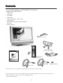
Your new NEC MultiSync® LCD2335WXMTM monitor box*
contains the following items:
•
•
•
•
•
•
•
•
LCD monitor
Power Cord
AC Adapter
Audio Cable
Video Signal Cable – VGA to VGA
User’s Manual
Wireless Remote Control and AA Batteries
RF Cable
• Relay Connector
Power Cord
Video Signal Cable
(D-SUB to D-SUB Cable)
Wireless Remote Control
and AA Batteries
AC Adapter
User’s Manual
RF cable
Relay connector
Audio Cable
*Remember to save your original box and packing material to transport or ship the monitor.
The following optional components are available to use with the LCD2335WXM. To obtain the optional components and
additional information, contact Customer Service at (800) 632-4662.
• Macintosh Cable Adapter
3
C omp
one
nt Name
unc
ompone
onent
Namess and FFunc
uncttions
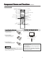
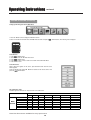
Main Unit
Front view of main body
LED lights Green color --- Power is ON.
LED lights Orange --- Monitor is in "Power Saving Mode".
LED is off --- Power is OFF.
1
Indicator for
Power
2
IR receiver
IR receiver.
3
Power
Turn on or off the main body.
4
Menu
Open or Close the OSD menu.
5
Channel
Select the next lower channel / higher channel (TV/AV mode) ; OSD function for selecting (PC mode).
6
Volume
Lower / Raise the sound volume (TV/AV mode) ; OSD function for adjusting (PC mode).
7
Source
Selection TV, AV-1(COMPOSITE), AV-2(S-VIDEO), AV3(YCbCr / YPbPr), AV4(YCbCr / YPbPr) ,
RGB1 PC or RGB2 DVI.
8
Enter
Enter for adjusting or next page.
Rear view of main body
1
RF in
Please connect to antenna or cable TV signal.
2
VGA input
Please use the 15-pin VGA cable in the package
contents.
3
AV3-in
For component Video input and audio.
4
AV1/2-in
For composite video or S-video input and audio.
5
AV4-in
For component Video input and audio.
6
PC Audio in
Please connect the audio from sound card to PC
Audio in.
7
DC in
Please connect to your 19V power supply.
8
DVI in
Please use the DVI cable for signal input
9
Kensington
Lock hole
It can be locked with Kensington lock.
10
Speaker -R
Connect to Right-speaker
11
Speaker -L
Connect to Left-speaker
12
Audio out
For Audio R/L output & Subwoofer.
4
C omp
one
nt Name
unc
ompone
onent
Namess and FFunc
uncttions continued
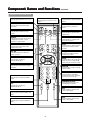
Remote Control
TV TUNER
LED INDICATION
POWER ON/OFF
SOURCE SELECT
SLEEP
CH-LOCK
ZOOM
ASPECT
CCD (Close Caption Display)
PIP
SWAP
STILL
VOLUME UP / DN (ST)
CH UP / DN (ST)
MUTE
MENU
LAST-CH
PROGRAM / ADJUST (WX)
SELECT (ST)
ENTER
DISPLAY
MTS
NUMBER KEYPAD
AV2
AV1
AV3
RGB-1VGA
AV4
RGB-2 DVI
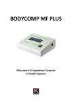
Installing the Batteries
Handling the Remote Control
Use the remote control within about 16 feet from front of the unit’s remotecontrol sensor and within 30 degrees on both sides.
1. Open the battery cover.
Slide back and remove the battery cover in
the direction of the arrow.
z
2. Installing the batteries.
Install two included Size AA batteries
observing the correct polarities(+,-).
z
Within 30 degrees
Within 30 degrees
About 10 feet
About 10 feet
About 16 feet
3. Close the battery cover.
Replace the battery cover in the direction
of the arrow and snap it back into place.
z
ATTENTION
Do not drop the remote control.
To avoid possible failures, do not splash the remote control with water
or put it on a wet object.
zIf leaving the remote control out of use for an extended period of time,
remove the batteries from it.
zIf the remote control does not respond properly, replace the batteries.
zStrong light such as direct sunlight exposed on the photoreceptor of
the remote control can cause operational failure. Position this unit to
avoid direct contact with such light.
z
z
CAUTION
Do not mix new and old batteries together. The batteries could explode or
leak, resulting in fires, physical injury, or stains.
zWhen inserting batteries, observe their correct polarities as marked on the
product. If inserted in the wrong direction, the batteries could explode or leak,
resulting in fires, physical injury, or stains.
z
5
C omp
one
nt Name
unc
ompone
onent
Namess and FFunc
uncttions continued
Remote Control (continued)
POWER
TV
Source
Press this button to turn the TV on or off.
Press this button to choose TV as the
source.
Press this button to select the INPUT
Source.
SLEEP
ZOOM
Press this button to activate the Sleep
Timer menu.
Press this button to change the
picture
CH-LOCK
CCD
Press this button to select the V-chip
function.
Press this button to show the Close
Caption menu.
ASPECT
SWAP
Press this button to selcet how the picture
is displayed on the screen; 4:3,16:9,
Panoramic, or Cinema modes
Press this button to exchange main
picture with PIP picture.
STILL
PIP
Press this button to show the PIP and
change the size of PIP.
Press this button to freeze the picture.
Press it again to return to normal
operation.
VOL ϧϰ
CH ϧϰ
Press these two buttons to adjust the
volume up or down
Press these two buttons to select
the channel up or down.
MENU
MUTE
Press this button to select the
On Screen Display Menu.
Press this button to turn off the sound.
Press it once more or press the S
volume up button to return the sound.
DISPLAY
Press this button to show the input signal
information.
LAST CH
Press this button to return to the last
Channel viewed.
MTS
Press this button to select Multichannel television sound. This button
operates only in the TV mode.
AV2
Press this button to select the S-VIDEO
INPUT.
NUMBERS KEYPAD
Press these buttons to access the
corresponding TV channels.
AV1
Press this button to select the
COMPOSITE INPUT.
AV3
Press this button to select the AV3
YCbCr / YPbPr INPUT.
RGB1
Press this button to select the RGB1 VGA
INPUT.
AV4
Press this button to select the AV4
YCbCr / YPbPr INPUT.
RGB2
Press this button to select the RGB2 DVI
INPUT.
6
Ins
ion Ins
truc
Instt allat
llation
Instruc
tructtions
Viewing Angle Adjustment
This product is designed to allow users to have a comfortable viewing angle.
The viewing angle can be adjusted from -5°to +20°.
Warning: Do not force the LCD Monitor over its maximum viewing angle as stated
above. Attempting this will result in damaging the Monitor and Monitor stand.
Detaching Main Body From Its Stand
Important: Place the monitor on a clean, flat surface that will not scratch the front
or glass surfaces of the display unit.
1. Remove the rear cover from rear stand assembly
2. Remove the 5 screws from the hinge bracket
3. Remove the stand from main body
1
2
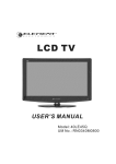
Interface for Arm Applications
Before installing to mounting device, please refer to Fig.1-5.
The rear of this LCD display has four integrated 4 mm, 0.7 pitches threaded nuts,
as well as four 5 mm access holes in the plastic covering as illustrated in Figure 18. These specifications meet the VESA Flat Panel Monitor Physical Mounting
Interface Standard (paragraphs 2.1 and 2.1.3, version 1, dated 13 November
1997).
100mm x 100mm
Screw Mounting Options
100mm
100mm
Note 1: Please using Ø 4mm x 8mm (L) screw for this application.
Note 2: The LCD monitor should only be used with an approved arm (e.g. GS
mark). To meet the safety requirements, the monitor must be mounted to an arm
which guaranties the necessary stability under consideration of the weight of the
monitor.
7
4mm ,0.7pitch threaded holes x4
Ins
ion Ins
truc
Instt allat
llation
Instruc
tructtions continued
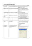
Connecting to a Antenna / Cable
Make sure that the power switch of the LCD MONITOR is turned off and that the unit is disconnected from the AC power source.
Monitor rear panel
Antenna
Precautions when connecting the antenna
Use a coaxial cable which is free from interference. Avoid using a parallel flat wire as interference may occur, causing the reception to become unstable and
noise to appear on the screen.
zAvoid using an indoor antenna as this may be affected by interference and poor reception.
zKeep the power cord as far away from the antenna wire as possible.
zAuto Tuning please refer to page 24
z
VHF(300-Ohm) antenna / UHF antenna
When using a 300-ohm twin lead from an outdoor antenna, connect the VHF or UHF antenna leads to the screws of the VHF or UHF adapter. Plug
the 300-ohm to 75-ohm adapter into the antenna on the LCD MONITOR.
When both VHF and UHF antennas are combined
Attach an optional antenna cable signal combiner to the LCD MONITOR antenna terminal, and connect the cables to the antenna mixer. Consult your
local electronics retailer about available signal combiners.
Reconnect the unit to the AX power source and turn on the power.
Using the Remote Control or User Controls, select the "CHANNEL SETTING MENU". Select the appropriate menu based upon which source (cable
or antenna) is being used.
Refer to pages 15 and 16 for further information on the "CHANNEL SETTING MENU" as well as for information on how to use the "AUTO
PROGRAM" function to program available channels.
8
Ins
ion Ins
truc
Instt allat
llation
Instruc
tructtions continued
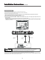
Connecting to a Video Components
1. Make sure that the power switch of the LCD MONITOR is turned off.
2. Make sure that the power switch of the Video component is turned off.
Set-Top Box
DVD/VCR/LD/IRD
Camera
Video game
DVD/VCR/LD/IRD
RCA A/V cable
S-VIDEO cable
Camera
Adapter
Video game
Sound output
from PC
VGA output
from PC
DVI output from PC
Antenna
Cable
Audio Amp
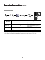
Applicable video signals for each input
nput terminal
termi
(See page 12 for details)
Terminal
Type
AV1
AV2
RCA
Video (Composite)
S-Video
Component
DVI
D-sub
PC/STB
RGB
{
Remarks
Refer to page12
{
Refer to page 12
1080i/720P/480P/480i inputs.
AV3
{
AV4
{
Refer to page 12
1080i/720P/480P/480i inputs.
Refer to page 12
RGB1
{
RGB2
{
Refer to page 12
Refer to page 12
({: Available)
9
Ins
ion Ins
truc
Instt allat
llation
Instruc
tructtions continued
Connecting to a PC
Choose an appropriate site and install the product on a level table where the stand is secure.
Ensure that a power socket is readily accessible near the place where you install the LCD MONITOR.
Make sure that the power switch of this device is turned off.
1. Make sure that the display signal of the personal computer to be used is compatible with the specifications of this device.
See "Product Specifications" concerning the specifications of this device.
2.Make sure that the power switch of the personal computer is turned off.
3.Connect the signal input terminal (RGB 1 or RGB 2) on the rear panel of this device to the display signal output terminal of the
personal computer.
z
z
Use a cable that fits the input terminal of this device and the output terminal of the personal computer.
Depending on the type of personal computer being connected, the use of an optional conversion adapter or the adapter provided with the personal
computer may be necessary in some cases. For details, refer to the instruction manual of the personal computer or ask the personal computer
manufacturer or your local retail.
Audio input
from PC.
Note
15 Pin D-sub
VGA
connector
DVI Connector
PREVENTION OF SCREEN BURN
Continuous on-screen display of fixed (non-moving) images, such as video games, stock market quotations,
computer generated graphics and other patterns can cause permanent damage to the LCD MONITOR.
Such "SCREEN BURN-IN" constitutes misuse and IS NOT COVERED by our Factory Warranty.
Subwoofer Output provides a single un-amplified audio output that passes along the audio signal from the LCD MONITOR.
Note: When using a Home Theater audio system with this LCD MONITOR, please connect the sub woofer (if originally supplied with the audio
system) directly to the Home Theater components subwoofer terminal.
10
Op
erat
ing Ins
truc
Ope
ating
Instruc
tructtions
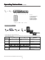
Turning Power On and Off
Power Lamp
To turn the LCD MONITOR power ON/OFF, press the POWER
button or the ON/OFF button on the remote control.
The power lamp will light and turn to green, the LCD MONITOR
will turn on.
Note: During normal use, the main power switch is set in the ON position.
z
Power lamp
Power
lamp
Power
lamp
Off
Off
Lights green
On
Operation
The OFF button on the remote control or
the POWER button is OFF.
When the power switch is ON, and the
ON button on the remote control or the
POWER button is ON.
POWER button
Lights orange
On
When the power switch is ON, and the
PC is in power save mode.
When the indicator lamp lights orange or the message “No cable
connected” or “Going to sleep” appears on the screen, there is
something abnormal about the status of the reception.
See Trouble Shooting.
CAUTION
Avoid repeatedly turning the LCD MONITOR on and off at short time
intervals. Failures might result from doing so.
zIf a power failure occurs while the main unit is running, it will be powered
on upon recovery from the failure. To prevent the power from returning
unexpectedly, possibly causing damage, turn off the main power switch
when after power failure occurs. Unplug the AC power source to the AC
adapter for 30 seconds to reset the unit.
z
POWER
ON/OFF
button
11
Op
erat
ing Ins
truc
Ope
ating
Instruc
tructtions continued
SOURCE button
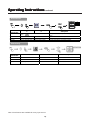
Volume Adjustment
VOLUME buttons
ENTER
TV>AV>PC
CH
The volume can be adjusted by pressing the S and T buttons
of the remote control.
MENU
Volume setting value
Adjustment status guide
TV
z
When
the volume buttons are pressed, the volume adjustment
status guide will be displayed.
zThe volume will increase when the VOL+ (or S) button is pressed while
SOURCE
the guide is being displayed.
The volume will decrease when the VOL- (or T) button is pressed while
the guide is being displayed.
z
VOLUME
control
Audio Mute
MUTE
The audio volume can be temporarily muted by pressing the
MUTE button of the remote control.
When the MUTE button is pressed, the above icon will appear.
AV1, AV2, AV3
RGB1, RGB2,
AV4 buttons
The volume setting can be lowered by pressing the VOL- button while
the audio is muted.
zMuting can be cancelled by pressing the VOL+ button or the MUTE
button while the audio is muted.
z
Selecting AV Inputs
z
Input
can be switched by pressing the AV1, AV2, AV3, AV4,
RGB1, or RGB2 buttons
z
Input can be switched in the sequence TVJAV1 JAV2J AV3
JAV4 J RGB1 VGA J RGB2 DVI by pressing the SOURCE
button and then select the Input with the select keys
STand then press the ENTER
button.To select a TV
station, press the TV button.
TV
AV1
RGB2 DVI
AV2
RGB1 VGA
AV3
AV4
12
Op
e rat
ing Ins
truc
Ope
ating
Instruc
tructtions continued
Main buttons:
1. PICTURE PARAMETERS MENU
2. PC PARAMETERS MENU
3. AUDIO SETTING MENU
4. PICTURE-in-PICTURE MENU
5. CHANNEL SETTING MENU
6. PARENTAL CONTROLS MENU
7. GENERAL SETTING MENU
Picture Parameters
BRIGHTNESS
CONTRAST
COLOR
TINT
COLOR TEMP
FLESHTONE
SHARPNESS
WARM
NORMAL
COOL
USER
USER R
0
USER G
USER B
1. Press the “MENU” button to display the Main Menu screen.
2. Press the ENTER button to confirm then use the S and T SELECT buttons to select the item to be adjusted and then use the W and X ADJUST
buttons to adjust the selected items.
Selected
characters
BRIGHTNESS
CONTRAST
W
Black
is
subdued
for
X
increased
overall Black is set to off for increased overall
darkness.
brightness.
Narrows the gap between light and dark.
Broadens the gap between light and dark.
Setup hint
Adjust as desired.
Adjust for maximum visibility to suit the
ambient brightness.
COLOR
Decrease color level.
Increase color level.
Adjust as desired.
TINT
Enhances red and weakens green.
Enhances green and weakens red.
Adjust as desired.
COLOR TEMP
Normally set to NORMAL .
FLESHTONE
ON
OFF
Set to ON for richer skin color.
SHARPNESS
SOFT
SHARP
Normally set to the “0” position; shift to the
minus (-) side for a softer picture and plus (+)
for a sharper picture.
Note: Not all menus are available for every input source.
13
Op
erat
ing Ins
truc
Ope
ating
Instruc
tructtions continued
PC Parameters
AUTO
CLOCK
YES
NO
PHASE
POSITION
Selected
characters
W
Setup hint
X
AUTO
Press the
light on.
ENTER button to make the word “YES” Normally set to NO mode. Adjust automatically for clock, phase, and
CLOCK
Reduces the dot clock.
Increases the dot clock.
Adjust for maximum character clarity.
PHASE
Slows the dot clock Phase
Advances the dot clock Phase
Adjust for clear character visibility.
POSITION
Press the PROGRAM button to adjust the display position
position.
Adjust the horizontal and vertical display positions.
Audio Setting
Selected
characters
W
X
Setup hint
BASS
Decreases bass.
Increases bass.
Adjust as desired.
TREBLE
Decreases treble.
Increaes treble.
Adjust as desired.
BALANCE
Decreases right volume level.
Increases left volume level.
Adjust as desired.
Note: Not all menus are available for every input source.
14
Op
e rat
ing Ins
truc
Ope
ating
Instruc
tructtions continued
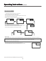
Channel Setting
*Note: The TV must be in TV mode for access to this Menu.
When operating the TV at first time, its TV system is at “default factory mode” and this mode cannot display the image normally on the screen. In
order to watch the TV program without problem, please refer to the follow steps to setup the TV system accordingly for normally display
1.SYSTEM setting: Select between antenna or cable (STD / HRC / IRC) TV system
SYSTEM
ANTENNA
AUTO PROGRAM
CABLE
FINE TUNE
CHANNEL EDIT
TV 12
ANTENNA
CABLE
ANTENNA
STD
CABLE
HRC
STD
STD 12
IRC
HRC
IRC
STD
HRC 12
HRC
IRC
STD
HRC
SELECT:
ENTER:
ADJUST:
IRC
RETURN: MENU
2. Auto Program setting
AUTO PROGRAM:Auto search channels
SYSTEM
AUTO PROGRAM
FINE TUNE
CHANNEL EDIT
SELECT:
ENTER:
ADJUST:
RETURN: MENU
3.FINE TUNE setting
AUTO: Use AUTO function to fine tune screen
SYSTEM
AUTO PROGRAM
FINE TUNE
CHANNEL EDIT
AUTO
MENU
MANUAL: Use MANUAL function to fine tune screen
SYSTEM
AUTO PROGRAM
FINE TUNE
CHANNEL EDIT
Note: Not all menus are available for every input source.
15
AUTO
MENU
IRC 12
Op
e rat
ing Ins
truc
Ope
ating
Instruc
tructtions continued
Channel Setting (Continued)
4.Channel Edit setting
CHANNEL ADD: Change the OSD channel number from Red to Green
SELECT:
ENTER:
ADJUST:
12
12
12
12
RETURN: MENU
CHANNEL DELETE:Change the OSD channel number from Green to Red
SELECT:
ENTER:
ADJUST:
Selected
characters
W
1.
SYSTEM
AUTO PROGRAM
FINE TUNE
CHANNEL EDIT
RETURN: MENU
X
ANTENNA
2. CABLE
1.Antenna or cable TV system selection.
2.If certain CABLE TV channels are poor or notpossible in [STD] mode, select[HRC] or [IRC].
CABLE
STD
Press
Setup hint
HRC
IRC
Auto program is Auto search channel with TV
Enter button to excute.
AUTO
MANUAL
ADD
DELETE
1. Use AUTO function to fine tune screen.
2. Use MANUAL function to fine tune scrceen.
1.Add function is add new channel with TV
2.Delete function is delete commercial channel for TV
Note: Not all menus are available for every input source.
16
Op
e rat
ing Ins
truc
Ope
ating
Instruc
tructtions continued
ASPECT
The ASPECT button will select how the video image appears on the
TV’s screen.
There are 4 selections.
ASPECT
16.9
Display a wide screen image.
4.3
Displays a 4:3 square picture with letterbox bands
PANORAMIC
CINEMA
ZOOM
Stretches the picture to increase the size of
Images in the center of the picture.
Magnifies the image to fill the screen with a picture.
16:9
CINEMA
4:3
PANORAMIC
Note : For RGB1 VGA and RGB 2 DVI, you can select 4:3 and 16:9
aspect mode.
Note : For HDTV 1080i, 720p and 480p inputs (AV3 / AV4) ,you can
select 4:3 and 16:9 aspect mode.
ZOOM
Each time the ZOOM button of the remote control is
Pressed, the image on the screen will be enlarged.
There are 10 selections, Zoom 0 (=Normal size ) to Zoom 9.
Note:ZOOM is available in 4:3 and 16:9 aspect mode.
Note: Not all menus are available for every input source.
17
Op
erat
ing Ins
truc
Ope
ating
Instruc
tructtions continued
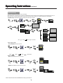
Picture-in-Picture
OFF
PIP
PBP
POP
OFF
OFF
PIP
PIP
SMALL
PBP
PBP
MEDIUM
POP
POP
LARGE
MULTI 1+12
AUDIO SOURCE
AUDIO SOURCE
PIP POSITION
MULTI 1+3
MULTI 1+1
PIP function description
W
Selected
OFF
PIP POSITION
Press
SMALL
X
Enter button to turn off.
MEDIUM
LARGE
Setup hint
Turn off Picture-in-Picture function
PIP POSITION
Change PIP display size & position.
PIP Position:
Use the S T buttons to adjust pictures to the up or down positions.
Use the W X buttons to adjust pictures to the right or left positions.
PBP
Press
POP
(MULTI 1+12) ÅÆ (MULTI 1+3) ÅÆ (MULTI 1+1)
use the S Tbuttons to select the PIP setting.
AUDIO SOURCE
MAIN
Select MAIN or PIP audio function.
Turn on Picture-by-Picture function
Enter button to turn on.
PIP
Note: Not all menus are available for every input source.
18
Op
e rat
ing Ins
truc
Ope
ating
Instruc
tructtions continued
PICTURE IN PICTURE (Continued)
Selecting PIP size
SOURCE
When the PIP button on the remote control is pressed, a black box will
appear on the screen.
PIP
SELECTSandT
Each time the PIP button is pressed, the size of box changes as follows.
SMALL
SMALL
MEDIUM
MEDIUM
LARGE
LARGE
PIP POSITION
PBP
Selecting PIP Source
While a black box appears on the screen, press SOURCE button and PIP SOURCE menu appears.
Picture mode will change in the following sequence, each time the remote button is pressed.
Select the SOURCE by using the T S select keys on the remote control. Then, press the
ENTER button.
Note: Not all menus are available for every input source.
19
PIP-OFF
Op
erat
ing Ins
truc
Ope
ating
Instruc
tructtions continued
PICTUREʳIN PICTURE (Continued)
Setting Up PIP through On Screen Main Menu
1.Press the "MENU" button to display the Main Menu screen.
2.Select " PICTURE IN PICTURE" Menu with W XʳADJUST button and press
ENTER button, then following menu will appear.
OFF
PIP
PBP
POP
AUDIO SOURCE
Select PIP size
1. Press
ENTER button.
2. Select the PIP size withʳS T SELECT button.
3. Press
ENTER button.
4. Press "MENU" button 2 times to return to PICTURE IN PICTURE Main Menu.
5. Press "MENU" to exit.
Select PIP Source
While a black box appears on the screen, press SOURCE button and PIP source
MENU appears.
Select the SOURCE by using theS T SELECT buttons on the remote control. Then
press the
ENTER button.
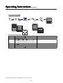
PIP Combination Table
Available signals are limited in PIP mode as shown in the table below.
Sub Source
Main
Source
RGB1 VGA
RGB2 DVI
TV
AV1 COMPOSITE
AV2 S-VIDEO
RGB1 VGA
X
O
O
O
O
O
RGB2 DVI
O
X
O
O
O
O
O
AV1 COMPOSITE
O
O
X
X
X
O
O
AV2 S-VIDEO
O
O
X
X
X
O
O
AV3 COMPONENT 1
O
O
O
O
O
X
X
AV4 COMPONENT 2
O
O
O
O
O
X
X
TV
O
O
X
X
X
O
O
Note: Not all menus are available for every input source.
20
AV3 COMPONENT1 AV4 COMPONENT2
O
Op
e rat
ing Ins
truc
Ope
ating
Instruc
tructtions continued
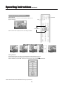
PICTUREIN PICTURE (Continued)
Change PIP Position
PICTURE IN PICTURE
After selecting PIP and PIP Source,
1.
2.
3.
4.
5.
Press the "MENU" button to display on the On Screen Main
Menu.
Select "PICTURE IN PICTURE" Menu withW X ADJUST
button.
Press
ENTER button. The following Menu and a
diagram will appear.
Select “PIP” with S T SELECT button.
Press the
ENTER Key, then select “PIP POSITION”
with S T SELECT button and a white ball appears in the
center of the diagram.
OFF
PIP
SMALL
PBP
MEDIUM
POP
LARGE
AUDIO SOURCE
PIP POSITION
6.
Move the PIP display with S T SELECT and W X ADJUST
buttons.
Press "MENU" button 2 times to return to "PICTURE IN
PICTURE" Menu
Multi PIP
After selecting PIP Size and PIP Source
1. Press the "MENU" button to display on the On Screen Main
Manu.
2. Select "PICTURE IN PICTURE" Menu witht W X ADJUST
button.
3. Press ENTER button. The following Menu and a diagram
will appear.
4. Select ” POP” with S TSELECT button.
5. Press the
ENTER Key, then select “MULTI” with S
T SELECT button
PICTURE IN PICTURE
OFF
PIP
PBP
POP
MULTI 1+12
AUDIO SOURCE
MULTI 1+3
MULTI 1+1
6.
Press "MENU" key 2 times to return to "PICTURE IN
PICTURE" Menu.
MULTI(1+12)
MULTI(1+3)
Note: Not all menus are available for every input source.
21
MULTI(1+1)
Op
erat
ing Ins
truc
Ope
ating
Instruc
tructtions continued
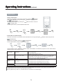
Other Functions
The MTS button is used only when using the TV channel selector.
z
Stereo and SAP (2nd Audio program) sound program
When a bilingual program is received, the sound mode display appears as shown on the right.
Press the MTS button to select the sound to be heard.
Each time the button is pressed, Stereo, SAP or Mono appears on the screen.
TV
CHANNEL:10
TV
SAP
CHANNEL:10
TV
MONO
CHANNEL:10 STEREO
Mono and SAP (2nd Audio program) sound program
TV
When a program is received, the sound mode display will appear as shown on the right,
and you can press the MTS button to select between SAP and mono sound.
CHANNEL:10
SAP
Each time the button is pressed, SAP or Mono will appear on the screen.
TV
CHANNEL:10
TV
SAP
CHANNEL:10
MONO
Monaural sound
When a monaural program is received, the sound mode display will be shown. You can press the MTS button to manually select monaural Sound.
NOTES
If the sound signal is not strong enough, press the MTS button until Mono appears on the screen, to receive a clear mono sound.
If the sound has a hiss noise or keeps switching between stereo and mono mode or SAP and mono mode due to signal strength, press the MTS button until
Mono appears on the screen to receive a clear mono sound.
z
z
Stereo sound
When a stereo program is received, the sound mode display will be shown.
You can press the MTS button to select the sound mode for stereo or mono reception.
Note: Not all menus are available for every input source.
22
MAIN:TV1
PIP:RGB1 VGA
CHANNEL:10 STEREO
Op
e rat
ing Ins
truc
Ope
ating
Instruc
tructtions continued
Parental Controls
Press “MENU” button and select PARENTAL CONTROLS menu with the W X PROGRAM ADJUST buttons, then press the
Enter the V chip Password: the factory preset code is 1111.
ENTER button.
MPAA RATING
ENTER button. Select rating by pressing the T S SELECT buttons. Press the
A second Menu appears. Select MPAA by pressing the
ENTER button to enter the rating. Press “MENU” button twice to return to parental controls. Press “Menu” button to exit screen.
TV PG RATING
1.Press “MENU” button and select PARENTAL CONTROLS menu with the W X PROGRAM ADJUST buttons, then press the
button. Enter the V chip Password: the factory preset code is 1111.
2.A second Menu appears. Select TV PG Rating by pressing the T SELECT button. Press the
ENTER
ENTER button, a third Menu appears.
Press the T S SELECT buttons to select rating, press the
ENTER button to enter the rating.
3.Select the ratings with T SPROGRAM ADJUST buttons. Press the ENTER button to set the rating, a dot will appear next to the rating.
4.To exit the sub menu press “MENU” button.
5.To exit the TV PG Rating menu, press the “MENU” button.
6.To exit Parental Controls Menu, press the “MENU” button a second time.
Note: Not all menus are available for every input source.
23
Op
erat
ing Ins
truc
Ope
ating
Instruc
tructtions continued
Parental Controls (Continued)
PASSWORD
1.Press “MENU” button and select PARENTAL CONTROLS menu with the W X PROGRAM ADJUST buttons, then press the
button. Enter the V chip Password: the factory preset code is 1111.
2.A second Menu appears. Select password by pressing theT SELECT button, press the
the numbers on the TV’s remote control.
ENTER
ENTER button, Enter the new password using
3.Enter the password a second time to continue.
4.A password confirmed window will appear. Press Menu button to exit Parental Controls.
This function will block out the selected channel or video input. The code to enter the LOCKS feature is a four-digit secret code number. Use the
number buttons to select the secret code.
Change Password
Enter Password
The factory preset code is (1111).
Enter NEW Password
This is used to enter a new four digit number you prefer.
NA; G; PG; PG-13; R; NC-17; X
When this is selected, you can block various types of movies and videotapes
MPAA RATING
based on motion picture ratings. Picture-in Picture will also be blocked
automatically.
NONE; TV-Y; TV-Y7 (FV); TV-G; TV-PG (D; L; S; V)
TV PG RATING
When this is selected, various types of television programming based on
parental guide ratings will be blocked. Picture-in-Picture will also be blocked
TV-14 (D; L; S; V); TV-MA (L; S; V)
automatically.
The password prevents viewing of any movie that you feel may be inappropriate due to its content. Use the S or T SELECT buttons to select the MPAA
RATING category that you want to block. Press the OK button to block the MPAA RATING that you have selected. Once the rating is selected, for example
PG-13, all MPAA rated PG-13 and higher (R, NC-17 and X) movies will be blocked.
Press RETURN to return to the previous menu.
Motion Picture Ratings Chart
NA
G
PG
PG-13
R
NC-17
X
Contains no rating. Not Rated and Not Applicable (NA) programs.
Movie has not been rated or ratings do not apply.
General audiences. All ages are permitted to watch.
Parental guidance suggested. Some material may not be suitable for children.
Parents strongly cautioned. Some material may be inappropriate for children under 13.
Restricted. Under 17 requires an accompanying parent or adult guardian.
No one 17 and under are permitted to watch.
Adults only.
24
Op
erat
ing Ins
truc
Ope
ating
Instruc
tructtions continued
TV PG RATING
This is to prevent viewing of any TV program that you feel may be inappropriate due to its content. Use the S or T SELECT buttons to highlight the category
that you want to block. Press the OK button to block the TV PG RATING that you have selected. Press the RETURN button to return to the previous menu.
TV Parental Guide Ratings Chart
TV-Y
TV-Y7
TV-G
TV-PG
TV-14
TV-MA
All children. The themes and elements in this program are specifically designed for a very young audience, including children from ages 26.
Directed to older children. Themes and elements in this program may include mild physical or comic violence, or may frighten children
under the age of 7.
General audience. It contains little or no violence, no strong language, and little or no sexual dialogue or situations.
Parental guidance suggested. The program may contain infrequent coarse language, limited violence, some suggestive sexual dialogue
and situations.
Parents strongly cautioned. This program may contain sophisticated themes, intense sexual situation, more intense violence and
intensely suggestive dialogues.
Mature audience only. This program may contain mature themes, indecent language, graphic violence and explicit sexual content.
㪝㩷㪭㪠㪦㪣㪜㪥㪚㪜
Fantasy Violence 㩷
㪭㪠㪦㪣㪜㪥㪚㪜
Moderate Violence
㪪㪜㪯㪬㪘㪣㩷㪚㪦㪥㪫㪜㪥㪫 Sexual Situations
㪝㪦㪬㪣㩷㪣㪘㪥㪞㪬㪘㪞㪜
Coarse Language
㪪㪬㪞㪞㪜㪪㪫㪠㪭㪜㩷㪛㪠㪘
Suggestive Dialogue
NOTE
If you block TV-14D, you will still permit TV MA programs; if you block TV-14DV, you will automatically block TV-MAV programs, but you will still permit
TV-MALS programs. This means that the TV will block violence in TV-14 and higher (TV-MA), but not language and sex.
25
Op
e rat
ing Ins
truc
Ope
ating
Instruc
tructtions continued
General Setting
OSD POSITION
OSD TIMEOUT
OSD LANGUAGE
OSD MENU LOCK
SLEEP TIMER
I/P INFO
FACTORY RESET
TRANSPARENCY
Selected
characters
T
S
Setup hint
OSD POSITION
Use the S T and W X buttons to adjust the OSD position
OSD TIMEOUT
10SEC--30SEC—1 MIN
Adjusts OSD display and on-screen time
OSD LANGUAGE
English—Japan—Espanol—Francais
OSD MENU LOCK
ON
Sets the language for the OSD.
1. Select “ON” to lock OSD MENU. A message appears
stating that the TV is lock.
2. Press the MENU button and volume increase (on the
keypad) simultaneously. A message appears stating that
the TV is unlocked.
SLEEP TIMER
Use the S T buttons to set the TV off time mode.
INPUT INFO
To display information about the input signal.
FACTORY RESET
YES
TRANSPARENCY
Use the W X buttons to adjust OSD menu transparency
OFF
Adjusts the OSD position
Set the TV off time for each mode (OFF/30MIN/ 60MIN/ 120
MIN)
Displays information about the input signal
NO
Resets all settings to FACTORY defaults.
Adjusts OSD MENU transparency
* Depending on the type of signal displayed, displays may not be optimized through automatic adjustment. Manually adjust to optimize them.
* When operating the TV at first time, its TV system is at “default factory mode” and this mode cannot display the image normally on the screen.In
order to watch the TV program without problem, please refer to the page 25 to setup the TV system accordingly for normally display.
26
Op
erat
ing Ins
truc
Ope
ating
Instruc
tructtions continued
Captions Menu
Setup Closed Caption
Press the CCD button on the remote control then press the
ENTER
button. Select MODE menu by pressing the
SELECT button and press
the
ENTER button.
Select the closed caption by pressing the
SELECT buttons. Press the
ENTER button.
To exit Captions Menu, press the MENU button twice.
To Select Box or Shadow display
Press the CCD button on the remote control and DISPLAY menu by pressing the
SELECT button and press the
ENTER button.
Select BOX or SHADOW. Press the
ENTER button.
To exit Captions Menu, press the MENU button twice.
Closed Captions are the dialogues, narration and/or sound effects of a television program or home video that are
displayed on the LCD Television screen.
Caption Display
Press the CCD button then press
Enter button.
[1]Press the CCD button on the remote control then press the ENTER button to
enter the captions Menu.
[2]Press the MENU button twice to exit.
[Captions] is for the program you are viewing.
Mode
CC1- -CC2- - TEX1---TEXT2
Channel (Captions)
CC1- -CC2
Channel
(Text)
TEX1---TEXT2
[Text] is for additional information such as news reports or a TV program guide.
This information covers the entire screen and viewing the TV program is not
possible. Text may not be available with every [C.C] program.
[1] is used for the primary language (usually English)
[2] is sometimes used for a second language (may very by region).
[3] is sometimes used for a third language (may very by region).
[4] is sometimes used for a fourth language (may very by region).
BOX
[1] is used for the primary language, and has a black back ground.
SHADOW
[1] is used for the primary language, and has a line back ground.
NOTE
CAPTION DISPLAY will not work when viewing a picture via COMPONENT input (AV3/AV4:Y-CbCr/Y-PbPr) or DVI-HDTV inputs.
CAPTION DISPLAY will not work for other Extended Data Services.
When PIP (Multi Picture) mode is on, CAPTION DISPLAY is activated on the selected display.
27
Fe
atu
Featu
aturre s
23” diagonal screen size adds a new option to information display visual offerings.
1280 x 768 resolution allows for crisp text and precise images.
No permanent phosphor image burn-in contributes to optimal screen performance and longer monitor life.
XtraView®technology allows for wide-angle viewing.
User-friendly, efficient design features the currently proposed VESA-standard mounting and an overall lightweight
construction for easy transport and installation.
Speaker Bar delivers an enhanced multimedia experience with amazing sound quality.
Low power consumption and reduced heat emission lead to a lower total cost of ownership.
NEC’s quality and reliability provide peace of mind with a 1-year warranty (including backlight) and 24/7
customer service and technical support.
No Touch Auto Adjust: No Touch Auto Adjust automatically adjusts the monitor to optimal settings upon initial
setup.
Reduced Footprint: Provides the ideal solution for environments requiring superior image quality but with size
and weight limitations. The monitor’s small footprint and low weight allow it to be moved or transported easily
from one location to another.
AccuColor® Control System with allows you to change between the color settings on your display to match
your personal preference.
Plug and Play: The Microsoft® solution with the Windows®95/98/ME/2000/XP operating system facilitates
setup and installation by allowing the monitor to send its capabilities (such as screen size and resolutions supported)
directly to your computer, automatically optimizing display performance.
Intelligent Power Manager (IPM™) System provides innovative power-saving methods, saving two-thirds of your
monitor energy costs.
Multiple Frequency Technology automatically adjusts monitor to the display card’s scanning frequency, thus
displaying the resolution required.
FullScan® Capability allows you to use the entire screen area in most resolutions, significantly expanding image size.
VESA Standard Mounting Interface allows users to connect their LCD monitor to any VESA standard third party
mounting arm or bracket. Allows for the monitor to be mounted on a wall or an arm using any third party compliant device. NEC recommends using mounting interface that comply with UL1678 standard in North America.
DVI-D: The digital-only subset of DVI created by the Digital Display Working Group (DDWG) for digital connections
between computers and displays. As a digital-only connector, analog support is not provided off a DVI-D connector. As a DVI-based digital only connection, only a simple adapter is necessary for compatibility between DVI-D
and other DVI-based digital connectors such as DFP and P&D.
28
Troub
le
sho
ot
ing
ouble
lesho
shoot
oting
No picture
•
•
The signal cable should be completely connected to the display card/computer.
The display card should be completely seated in its slot.
•
Front Power Switch and computer power switch should be in the ON position.
•
Check to make sure that a supported mode has been selected on the display card or system being used. (Please consult display card or
system manual to change graphics mode.)
•
Check the monitor and your display card with respect to compatibility and recommended settings.
•
Check the signal cable connector for bent or pushed-in pins.
Power Button does not respond
•
Unplug the power cord of the monitor from the AC outlet for a minimum of 30 seconds to turn off and reset the monitor.
Image persistence
•
Please be aware that LCD Technology may experience a phenomena known as Image Persistence.
•
Image persistence is when a residual or “ghost” image of a previous image remains visible on the screen. Unlike CRT monitors,
LCD monitors image persistence is not permanent, but constant images being displayed for a long period of time should be
avoided. To alleviate image persistence, turn off the monitor for as long as the previous image was displayed. For example, if an
image was on the monitor for one hour and a residual image remains, the monitor should be turned off for one hour to erase the
image.
NOTE: As with all personal display devices, NEC-Mitsubishi Electronics Display recommends using a moving screen saver at regular
intervals whenever the screen is idle or turning off the monitor when not in use.
Image is unstable, unfocused or swimming is apparent
•
Signal cable should be completely attached to the computer.
•
Use the OSD screen controls to focus and adjust display by increasing or decreasing the clock phase total. When the display
•
mode is changed, the OSD Image Adjust settings may need to be readjusted.
Check the monitor and your display card with respect to compatibility and recommended signal timings.
•
If your text is garbled, change the video mode to non-interlace and use 60Hz refresh rate.
Image of component signal is greenish
•
Check to see if the DVD/HD input connector is selected.
LED on monitor is not lit (no green or red color can be seen)
•
Power Switch should be in the ON position and power cord should be connected.
•
Make certain the computer is not in a power-saving mode (touch the keyboard or mouse).
Display image is not sized properly
•
•
Use the OSDscreen controls to increase or decrease the clock total.
Check to make sure that a supported mode has been selected on the display card or system being used. (Please consult display card or
system manual to change graphics mode.)
Selected resolution is not displayed properly
•
Use OSD information to enter Information menu and confirm that the appropriate resolution has been selected. If not, select
corresponding option.
No Sound
•
Check to see if speaker cable is properly connected.
•
•
Check to see if mute is activated.
Check to see if volume is set at minimum.
Remote Control is not available
•
Test the Remote Control’s batteries for strength/life.
•
•
Check if the batteries are inserted correctly.
Check if the Remote Control is pointed at the monitor’s remote sensor.
29
Troub
le
sho
ot
ing continued
ouble
lesho
shoot
oting
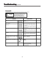
Symptoms
If the solution does not correct the symptoms, please contact your local Service center for assistance.
WARNING
DO NOT OPEN THE MONITOR.
Self servicing can be hazardous. There are no
user serviceable parts inside and opening or
removing covers may expose you to
dangerous shock hazards or other risks.
Refer all servicing to qualified personnel.
Symptom
Point to check
Check to see that the power cable is properly
connected.
There is no picture and the power-indicating lamp
is off.
See Page
11
Press the main switch.
The message “No cable connected” or “Going to
sleep” is displayed.
No sync signal is detected.
There is no picture and the power indicating lamp
lights orange.
Make sure that the computer, imaging equipment,
etc., is turned on.
Check that the signal cable is properly connected.
Make sure the computer is not in power-save mode.
Ensure that the input selection matches the
connection terminal.
The message “Invalid Mode.” is displayed.
An input signal is received abnormally.
32
Ensure that the input signal matches the monitor
specifications.
Check to see that the signal cable is properly
connected.
The power indicating lamp is lit normally but there
is no picture.
Check the contrast and brightness settings
(adjust them for higher contrast and brightness).
13
Check to see that the signal cable is properly
connected.
The display image appears slanted.
Adjust the clock frequency and the phase.
(Adjust the clock frequency first, the dot clock
phase next.) (RGB input)
Text displayed across the screen appears
vertically streaked, with the characters in vertical
columns blurred.
Text displayed across the screen appears blurred.
A fine pattern flickers when displayed on the
screen.
Adjust the clock phase till the desired clarity is
obtained.
(RGB input)
The remote control does not work.
Ensure that the batteries in the remote control are
inserted with the correct polarity.
Check to see that the batteries in the remote
control are functional.
30
14
14
5
Troub
le
sho
ot
ing continued
ouble
lesho
shoot
oting
Symptoms(continued)
Symptom
Point to check
The temperature of the display panel surface is
warm.
The LCD display panel works by lighting phosphors. In some cases, this
may cause the temperature of the panel surface to increase. Please note
that this is not a malfunction.
Points that do not light, points with brightness
different from that of the periphery, points with
color different from that of the periphery, etc.
High-precision technology is used to manufacture the LCD display panel,
However over the life of the LCD panel, a few pixel elements may fail.
This is not to be considered a defect in the panel.
Coarse horizontal stripes appear in FULL display.
Adjusting the Clock Phase will reduce the horizontal stripes. (RGB input)
The screen flickers in the form of horizontal lines
oscillating up and down.
(PC INPUT MODE only)
If the frequency from the computer is below 85Hz, try a higher frequency
(to a maximum limit of 85Hz). There may be a slight attenuation of the
current image.
The top surface of the monitor heats up.
When used for long periods of time, the top surface of the monitor may
heat up. This is not a malfunction.
Text characters
thickness.
are
displayed
with
varying
The display does not seem bright enough.
The thickness of characters and lines may vary when images with a
vertical resolution greater than 720 lines are displayed; however this is
not a malfunction.
The ambient temperature of the monitor may be low. Ambient temperatures
less than about 15° degrees, may cause lower luminance.
The panel protection circuit automatically lowers the luminance, and is
not a malfunction. The luminance will be restored when power is turned
on for a while.
The display does not seem bright enough. (RGB
input)
The setup-frequency setting in RGB input may be set to PC mode. When set
to PC mode, the luminance is lowered by about 10% than when set as Movie
mode. This is not a malfunction. If you do not mind flicker on the display,
please switch to Movie mode.
31
Troub
le
sho
ot
ing continued
ouble
lesho
shoot
oting
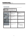
Symptoms(continued)
Make the checks suggested below depending on the symptoms observed. If the symptoms remain unresolved, contact your dealer.
WARNING
Symptom
snowy picture - poor sound
DO NOT OPEN THE MONITOR.
Self servicing can be hazardous. There are
no user serviceable parts inside and opening or
removing covers may expose you to dangerous
shock hazards or other risks.
Refer all servicing to qualified personnel.
Possible reason
Remedy
(1)Connection of antenna/cable lead in wire to
the TV is poor.
(2)Corroded or poor antenna/cable
connections.
(3)Antenna has moved position.
(4)Adverse weather conditions.
(5)Transmitter problems.
(1)Make new connection and/or change
antenna plug.
(2)Make new connections or use new cable.
(3)Re-align the antenna.
(4)None.
(5)Check with the local Operator.
(1)Antenna has moved position.
(2)Adverse weather conditions.
(3)Transmitter problems.
(4)AV Input is not set correctly.
(5)Corroded or poor antenna / cable
connections.
(1)Re-align the antenna.
(2)None.
(3)Check with the local Operator.
(4)Check the external equipment connected.
(5)Make new connections or use new cable.
(1)Interference from electrical or mechanical
motors, fluorescent lights, portable radios
etc.
(2)Corroded or poor antenna/cable
connections.
(1)Check devices for shielding and renew if
necessary or move further from TV.
(2)Make new connections or use new cable.
(1)TV may be in AV mode.
(1)Press the PROGRAM button or the 0 to 9
buttons on your remote control to return to
normal TV mode.
(2)Check picture / sound controls (go to MAIN
MENU).
(3)Press POWER ON / OFF button.
(4)Make new connections or use new cable.
multiple images - sound O.K
intermittent interference
(2)Picture/sound setting is set to minimum.
(3)TV is in standby or power save mode.
(4)Corroded or poor antenna / cable
connections.
no picture or sound
32
Re fe rence
ncess
NEC-Mitsubishi Monitor Customer Service & Support
Customer Service and Technical Support:
(800) 632-4662
Fax:
(800) 695-3044
Parts and Accessories/Macintosh
Cable Adapter:
(888) NEC-MITS [888-632-6487]
Warranty Information:
www.necmitsubishi.com/warranty
OnlineTechnicalSupport
www.necmitsubishi.com/support
Sales and Product Information
Sales Information Line:
Canadian Customers:
Government Sales:
Government Sales email:
(888) NEC-MITS [888-632-6487]
(866) 771-0266, Ext#: 4037
(800) 284-6320
[email protected]
ElectronicChannels
World Wide Web:
Product Registration:
European Operations:
www.necmitsubishi.com
www.necmitsubishi.com/productregistration
www.nec-mitsubishi.com
DriversandDownloads
www.necmitsubishi.com/downloads
33
Sp e c if
ic
at
ions
ific
icat
ations
LCD Module
Diagonal :
Viewable Image Size :
Native Resolution (Pixel Count) :
Input Signal
PC INPUT
Video :
Sync :
Active matrix; thin film transistor (TFT)
liquid crystal display (LCD); 0.390 mm dot
pitch; 500cd/m2 white luminance;
500:1 contrast ratio, typical
ANALOG 0.7 Vp-p/75 Ohms Digital Input: DVI
Separate sync. TTL Level
Horizontal sync. Positive/Negative
Vertical sync. Positive/Negative
VIDEO INPUT
Composite 1.0V p-p Input Impedance 75 Ohm RCA-INPUT
Y/C Y:0.7V p-p C:0.283V p-p Input Impedance 75 Ohm S-TERMINAL-INPUT
2 component 1.0/0.7V p-p Input Impedance 75 Ohm RCA-INPUT
AUDIO INPUT
RCA PIN-JACK L/R 3 INPUT, STEREO Mini Jack 1INPUT
500mV rms Input Impedance 22 Kohm
RCA PIN-JACK L/R 1OUTPUT 500mV rms
RCA PIN-JACK Subwoofer 1 OUTPUT 300mV rms
Over 16,000,000
Dependent on display card used.
85°/85° (CR>10)
85°/85° (CR>10)
31.5 kHz to 60.0 kHz
Automatically
56.0 Hz to 75.0 Hz
Automatically
720 x 400*1 :VGA text
Some systems may not support all modes listed.
640 x 480*1 @ 60 Hz to 75 Hz
800 x 600*1 @ 56 Hz to 75 Hz
1024 x 768*1 @ 60 Hz to 75 Hz
1280 x 768 @ 60 Hz to 75 Hz...................NEC-Mitsubishi Electronics Display cites
1152 x 864*1 @ 60 Hz to 70 Hz
recommended resolution at 60 Hz for
1280 x 960*1 @ 60 Hz to 70 Hz
optimal display performance.
1280 x 1024*1 @ 60 Hz to 70 Hz
AUDIO OUTPUT
Display Colors
Maximum
Viewing Angles
Synchronization
Range
Resolutions Supported
23.0 inch
23.0 inch
1280 x 768
Left/Right :
Up/Down :
Horizontal :
Vertical :
NTSC
HDTV: 480i (60 Hz), 480p (60 Hz), 576i (50 Hz), 720p (50/60 Hz), 1080i (50/60
Hz)
Active Display Area
Horizontal :
Vertical :
Power Supply
Current Rating
Dimensions
Weight
Environmental Considerations
Operating Temperature :
Humidity :
Feet :
Storage Temperature :
Humidity :
Feet :
19.7 inch
11.8 inch
100 – 240 V ~ 50/60 Hz
19V DC 6.3A
580.0 mm (W) x 467.5 mm (H) x 210.0 mm (D)
22.8 inches (W) x 18.4 inches (H) x8.3 inches (D)
10.0 kg
22.0 lbs
5°C to 35°C/41°F to 95°F
30% to 80%
0 to 12,001 Feet
-10°C to 60°C/14°F to 140°F
10% to 85%
0 to 40,000 Feet
*1 Interpolated Resolutions: When resolutions are shown that are lower than the pixel count of the LCD module, text may appear
different. This is normal and necessary for all current flat panel technologies when displaying non-native resolutions full screen. In flat
panel technologies, each dot on the screen is actually one pixel, so to expand resolutions to full screen, an interpolation of the
resolution must be done.
NOTE: Technical specifications are subject to change without notice.
34
Limit
ed W
ar
Limite
War
arrrant
antyy
NEC-Mitsubishi Electronics Display of America, Inc. (hereinafter “NMD-A”) warrants this Product to be free
from defects in material and workmanship and, subject to the conditions set forth below, agrees to repair or
replace (at NMD-A’s sole option) any part of the enclosed unit which proves defective for a period of one (1)
year from the date of first consumer purchase. Spare parts are warranted for ninety (90) days. Replacement
parts or unit may be new or refurbished and will meet specifications of the original parts or unit.
This warranty gives you specific legal rights and you may also have other rights, which vary from state to state.
This warranty is limited to the original purchaser of the Product and is not transferable. This warranty covers
only NMD-A-supplied components. Service required as a result of third party components is not covered under
this warranty. In order to be covered under this warranty, the Product must have been purchased in the U.S.A.
or Canada by the original purchaser. This warranty only covers Product distribution in the U.S.A. or Canada
by NMD-A. No warranty service is provided outside of the U.S.A. or Canada. Proof of Purchase will be
required by NMD-A to substantiate date of purchase. Such proof of purchase must be an original bill of sale
or receipt containing name and address of seller, purchaser, and the serial model number of the product.
It shall be your obligation and expense to have the Product shipped, freight prepaid, or delivered to the
authorized reseller from whom it was purchased or other facility authorized by NMD-A to render the services
provided hereunder in the original package. All Products returned to NMD-A for service MUST have prior
approval, which may be obtained by calling 1-800-632-4662. The Product shall not have been previously
altered, repaired, or serviced by anyone other than a service facility authorized by NMD-A to render such
service, the serial number of the product shall not have been altered or removed. In order to be covered by
this warranty the Product shall not have been subjected to displaying of fixed images for long periods of time
resulting in image persistence (afterimage effects), accident, misuse or abuse or operated contrary to the
instructions contained in the User’s Manual. Any such conditions will void this warranty.
NMD-A SHALL NOT BE LIABLE FOR DIRECT, INDIRECT, INCIDENTAL, CONSEQUENTIAL, OR OTHER TYPES
OF DAMAGES RESULTING FROM THE USE OF ANY NMD-A PRODUCT OTHER THAN THE LIABILITY
STATED ABOVE. THESE WARRANTIES ARE IN LIEU OF ALL OTHER WARRANTIES EXPRESS OR IMPLIED,
INCLUDING, BUT NOT LIMITED TO, THE IMPLIED WARRANTIES OF MERCHANTABILITY OR FITNESS FOR
A PARTICULAR PURPOSE. SOME STATES DO NOT ALLOW THE EXCLUSION OF IMPLIED WARRANTIES
OR THE LIMITATION OR EXCLUSION OF LIABILITY FOR INCIDENTAL OR CONSEQUENTIAL DAMAGES SO
THE ABOVE EXCLUSIONS OR LIMITATIONS MAY NOT APPLY TO YOU.
This Product is warranted in accordance with the terms of this limited warranty. Consumers are cautioned that
Product performance is affected by system configuration, software, the application, customer data, and
operator control of the system, among other factors. While NMD-A Products are considered to be compatible
with many systems, specific functional implementation by the customers of the Product may vary. Therefore,
suitability of a Product for a specific purpose or application must be determined by consumer and is not
warranted by NMD-A.
For the name of your nearest authorized NEC-Mitsubishi Electronics Display service facility, contact NECMitsubishi Electronics Display of America at 1-800-632-4662.
35
TCO’99
Congratulations! You have just purchased a TCO’99 approved and
labelled product! Your choice has provided you with a product developed
for professional use. Your purchase has also contributed to reducing the
burden on the environment and also to the further development of
environmentally adapted electronics products.
Why do we have environmentally labelled computers?
In many countries, environmental labelling has become an established method for encouraging the adaptation of goods and services to the environment. The main problem, as far as
computers and other electronics equipment are concerned, is that environmentally harmful
substances are used both in the products and during the manufacturing. Since it has not been
possible for the majority of electronics equipment to be recycled in a satisfactory way, most
of these potentially damaging substances sooner or later enter Nature.
There are also other characteristics of a computer, such as energy consumption levels, that are
important from the viewpoints of both the work (Internal) and natural (external) environments.
Since all methods of conventional electricity generation have a negative effect on the
environment (acidic and climate-influencing emissions, radioactive waste, etc.), it is vital to
conserve energy. Electronics equipment in offices consume an enormous amount of energy
since they are often left running continuously.
What does labelling involve?
This product meets the requirements for the TCO’99 scheme which provides for international and
environmental labelling of personal computers. The labelling scheme was developed as a joint
effort by the TCO (The Swedish Confederation of Professional Employees), Svenska
Naturskyddsforeningen (The Swedish Society for Nature Conservation) and Statens Energimyndighet
(The Swedish National Energy Administration).
The requirements cover a wide range of issues: environment, ergonomics, usability, emission of
electrical and magnetic fields, energy consumption and electrical and fire safety.
The environmental demands concern restrictions on the presence and use of heavy metals,
brominated and chlorinated flame retardants, CFCs (freons) and chlorinated solvents, among other
things. The product must be prepared for recycling and the manufacturer is obliged to have an
environmental plan which must be adhered to in each country where the company implements its
operational policy. The energy requirements include a demand that the computer and/or display,
after a certain period of inactivity, shall reduce its power consumption to a lower level in one or
more stages. The length of time to reactivate the computer shall be reasonable for the user.
Labelled products must meet strict environmental demands, for example, in respect of the reduction
of electric and magnetic fields, physical and visual ergonomics and good usability.
Environmental Requirements
Flame retardants
Flame retardants are present in printed circuit boards, cables, wires, casings and housings. In turn,
they delay the spread of fire. Up to thirty percent of the plastic in a computer casing can consist of
flame retardant substances. Most flame retardants contain bromine or chloride and these are
related to another group of environmental toxins, PCBs, which are suspected to give rise to severe
health effects, including reproductive damage in fisheating birds and mammals, due to the bio36
TCO’99 –continued
accumulative* processes. Flame retardants have been found in human blood and researchers fear
that disturbances in foetus development may occur.
TCO’99 demand requires that plastic components weighing more than 25 grams must not contain
flame retardants with organically bound chlorine and bromine. Flame retardants are allowed in
the printed circuit boards since no substitutes are available.
Lead**
Lead can be found in picture tubes, display screens, solders and capacitors. Lead damages the
nervous system and in higher doses, causes lead poisoning.
TCO’99 requirement permits the inclusion of lead since no replacement has yet been developed.
Cadmium**
Cadmium is present in rechargeable batteries and in the colourgenerating layers of certain
computer displays. Cadmium damages the nervous system and is toxic in high doses.
TCO’99 requirement states that batteries, the colourgenerating layers of display screens and the
electrical or electronics components must not contain any cadmium.
Mercury**
Mercury is sometimes found in batteries, relays and switches, Mercury damages the nervous system
and is toxic in high doses.
TCO’99 requirement states that batteries may not contain any Mercury. It also demands that no
mercury is present in any of the electrical or electronics components associated with the display unit.
CFCs (freons)
CFCs (freons) are sometimes used for washing printed circuit boards. CFCs break down ozone and
thereby damage the ozone layer in the stratosphere, causing increased reception on Earth of
ultraviolet light with consequent increased risks of skin cancer (malignant melanoma).
The relevant TCO’99 requirement; Neither CFCs nor HCFCs may be used during the manufacturing
and assembly of the product or its packaging.
*Bio-accumulative is defined as substances which accumulate within living organisms.
**Lead, Cadmium and Mercury are heavy metals which are Bio-accumulative.
To obtain complete information on the environmental criteria document, order from:
TCO Development Unit
SE-114 94 Stockholm
SWEDEN
FAX Number: +46 8 782 92 07
E-mail (Internet): [email protected]
You may also obtain current information on TCO’99 approved and labelled products by
visiting their website at: http://www.tcodevelopment.com/
37
Declaration of the Manufacturer
We hereby certify that the color monitors LCD2335WXM is in compliance
with Council Directive 73/23/EEC:
– EN 60950-1
Council Directive 89/336/EEC:
— EN 55022
— EN 61000-3-2
— EN 61000-3-3
— EN 55024
and marked with
NEC-Mitsubishi Electric Visual
Systems Corporation
4-13-23, Shibaura,
Minato-Ku
Tokyo 108-0023, Japan
NEC LCD2335WXM
PROPRIETARY NOTICE AND LIABILITY DISCLAIMER
The information disclosed in this document, including all designs and related materials, is the valuable property of NEC-Mitsubishi
Electronics Display of America and/or its licensors, as appropriate, reserve all patent, copyright and other proprietary rights to this
document, including all design, manufacturing, reproduction, use and sales rights thereto, except to the extent said rights are expressly
granted to others.
The NEC-Mitsubishi Electronics Display of America product(s) discussed in this document are warranted in accordance with the
terms of the Limited Warranty Statement accompanying each product. However, actual performance of each such product is
dependent upon factors such as system configuration, customer data and operator control. Since implementation by customers
of each product may vary, the suitability of specific product configurations and applications must be determined by the customer
and is not warranted by NEC-Mitsubishi Electronics Display of America.
To allow for design and specification improvements, the information in this document is subject to change at any time without
notice. Reproduction of this document or portions thereof without prior approval of NEC-Mitsubishi Electronics Display of
America is prohibited.
DECL
AR
AT ION OF CCONFORMI
ONFORMI
DECLAR
ARA
ONFORMITT Y
This device complies with Part 15 of FCC Rules. Operation is subject to the following two conditions. (1) This device may not cause
harmful interference, and (2) this device must accept any interference received, including interference that may cause undesired
operation.
U.S. Responsible Party:
Address:
Tel. No.:
NEC-Mitsubishi Electronics Display of America, Inc.
1250 North Arlington Heights Road, Suite 500
Itasca, Illinois 60143-1248
(630) 467-3000
Type of Product:
Display Monitor
Equipment Classification:
Class B Peripheral
Model:
MultiSync® LCD2335WXM™ (L234GC)
We hereby declare that the equipment specified above
conforms to the technical standards as specified in the FCC Rules.
Windows is a registered trademark of Microsoft Corporation. NEC is a registered trademark of NEC Corporation. All other brands
and product names are trademarks or registered trademarks of their respective owners.
As an ENERGY STAR® Partner, NEC-Mitsubishi Electronics Display of America has determined that this product meets the ENERGY STAR
guidelines for energy efficiency. The ENERGY STAR emblem does not represent EPA endorsement of any product or service.
PRINTED IN CHINA
P/N: HD67NV23010