1
ND-71548 (E)
ISSUE 2
Installation Manual
AUGUST 2002
NEC Corporation
To view the latest issue of this document go to NEC Knowledgebase @ http://www.kbase.cns.nec.com.au &search for NEC-7128
LIABILITY DISCLAIMER
NEC Corporation reserves the right to change the specifications,
functions, or features, at any time, without notice.
NEC Corporation has prepared this document for use by its employees and customers. The information contained herein is the property
of NEC Corporation and shall not be reproduced without prior written
approval from NEC Corporation.
All brand names and product names on this document are trademarks or registered trademarks of their respective companies.
Copyright 2002
NEC Corporation
PRODUCT LIABILITY
BEFORE THE USE OF THIS MANUAL
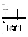
1. FOR SAFETY USE
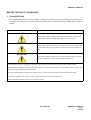
Here explains the safety use for the customer, which prevents danger to the life and damage to the property accidentally. The following are symbols and their meanings. Please read the following carefully before using this
manual.
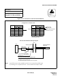
DESCRIPTION
SYMBOLS
DANGER
This symbol indicates danger. You might be involved in a situation that
could cause deadly and bodily injury if you take wrong action.
WARNING
This symbol indicates warning. You might be involved in a situation that
could cause bodily injury and serious system fault if you take wrong action.
ATTENTION
This symbol indicates attention. The system might not acheive its performance or lead to the system stall if you take wrong action.
This telephone system is designed for use in the country NEC provides and can not be used in any other country.
If system-down, malfunction, defects, and external factors (such as electricity failure) cause profit loss indirectly, NEC does
not take any responsibilities for the profit loss.
We pay careful attention to making this manual, however, when you find mistakes on this manual, notify to NEC.
Contact the supplier or the service technician if the system needs repairs and installation.
Please read all the manuals related to your system carefully.
ND-71548 (E)
PRODUCT LIABILITY
PL- 1
Issue 2
PRODUCT LIABILITY
2. NOTICE WHEN USED
2.1 Consideration of PBX, Power-related Equipment and Peripheral Equipment
This item describes the consideration before using PBX, the power-related equipment, and the peripheral equipment (such as console, MDF, DAU, telephone, PC, printer, etc).
Preserve the following:
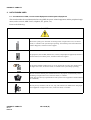
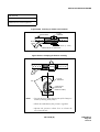
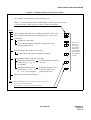
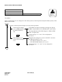
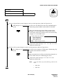
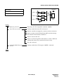
DANGER
When the system gives off smoke or burning smell, it might cause a fire, an electric
shock, or a failure if the system keeps operating. Turn off the power and confirm the
smoke disappears, and then contact supplier.
If equipment (such as PBX, Main Power, cabinet, and peripheral equipment) fall down
and be broken, turn off the power, and then contact the supplier.
PW
R
If the inside of PBX or Main Power is wet by liquid such as water, turn off the power.
It might cause a fire, an electric shock, or a failure if the system keeps operating.
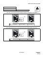
Do not touch the internal parts of Main Power for the purpose of disassembly and remodeling. It might cause a fire, an electric shock, or a failure.
(NEC does not take any responsibilities if the system or the equipment is disassembled
or remodeled.)
Do not put any container (such as vase, cup, and cosmetics) on Main Power and peripheral equipment. It might cause a fire, an electric shock, or a failure.
PRODUCT LIABILITY
PL- 2
Issue 2
ND-71548 (E)
PRODUCT LIABILITY
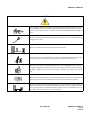
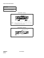
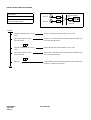
DANGER
Do not damage, remake, forcefully bend, forcefully extract, nor forcefully twist an electric code and a wiring to/from PBX, Main Power and peripheral equipment. It might
cause a fire, an electric shock, or a failure. If the wiring is damaged, ask the supplier to
fix it.
dust
Insert the electric plug into the outlet properly. Confirm no dust is on the blade of plug;
it might cause a fire.
PWR
Do not use other than the power designated when installed.
PWR
Do not try to fix or move Main Power by yourselves without the supplier or service technician’s help. Please ask them when the repair or the movement is necessary.
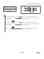
Do not put any metal or combustible object into a vent of PBX, Main Power, and the
peripheral equipment. If the object is in those equipment, turn off the power and ask the
supplier. It might cause a fire, an electric shock, or a failure if the system keeps operating.
Be careful of using the display part which the peripheral equipment has. In the case of
liquid crystal, the liquid is leaked and causes harm to human body and systems.
?
Before connecting customer-provided equipment (such as the other company products)
with NEC products such as PBX and peripheral equipment, ask the supplier and make
sure your equipment is compatible with NEC product. If it is not confirmed, do not connect them. It might cause a fire or an electric shock.
ND-71548 (E)
PRODUCT LIABILITY
PL- 3
Issue 2
PRODUCT LIABILITY
WARNING
Fix the equipment. Do not put any object on PBX and Main Power; it might be dangerous if the object should fall down.
When plugging off a plug, be sure to grip the plug and extract it. If you grip the code
and extract it, it might cause a fire and an electric shock.
If a fault is considered as the lightening cause, ask the supplier.
Other than fulfilling the appropriate humidity and temperature, it is necessary to consider the maintenance operation and the all-time ventilation in non-loading operation during day-off and night. For example, when the height above floor is 1 m (3.281 feet), the
temperature should be from 20 to 25 °C (68 to 77 °F ) and the humidity should be more
or less 50 %.
PRODUCT LIABILITY
PL- 4
Issue 2
ND-71548 (E)
PRODUCT LIABILITY
WARNING
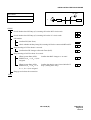
Be careful of using a battery as following:
Rechargeable lead battery is used as the emergency battery of PBX. Check the backup for an electricity failure.
Battery electrolyte is harmful to human body. If the battery electrolyte is put on the
cloth, clean it using enough amount of water.
Do not cause the battery short intentionally. Do not put it near fire or put it into fire.
Do not damage it, such as disassembly, falling, and impact.
The battery life varies depending on the surroundings. The battery life is approximately three years. If the battery is used outside with high temperature, the battery
life is shortened to approximately one year.
If not replacing terminal or dead battery, the PBX system will not work in case such as
power failure. Besides it might cause smoking or fire due to leaking battery electrolyte.
Perform the periodic diagnosis surely. Note that the battery is one of periodic replacement parts whose cost are charged to the customer. We recommend you to make a contract with supplier or service technician about the routine maintenance.
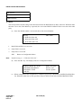
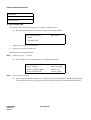
Snd: PWR:
Rcv:
TCP
155
UDP
Connection:
1
2
3
4
5
6
7
8
9
*
0
#
53
13 123
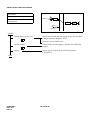
Do not touch the peripheral equipment by wet hand. Do not wet the peripheral equipment.
ENT
Do not touch the ink head and the internal of the printer. When replacing the ink ribbon
or the paper, make sure it is cool enough.
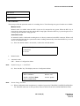
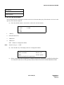
Sn
Rc d:
v: PW
R:
nn TCP
ec UDP
ti
3
on
:
Co
1
2
4
5
7
*
6
8
9
0
#
Pro
toc
ol:
TCP
ENT
155
53
13
123
Do not drop nor impact the peripheral equipment. It might cause a failure.
ND-71548 (E)
PRODUCT LIABILITY
PL- 5
Issue 2
PRODUCT LIABILITY
ATTENTION
Do not use benzine, thinner, and alcohol for cleaning. When it is difficult to clean dust
and dirt, put weaken neutral detergent onto a cloth, and give the cloth a wiring. Clean
dust and dirt with the cloth, and rub them with a dry cloth.
Thinner
Do not place equipment in the following:
Locations which receive direct sunlight
Locations where the moisture exceeds the allowed level
Locations which might be wet with water, oil, and chemicals
Locations which is particularly low in temperature (such as an ice compartment)
Locations which receive the electric wave or the magnetism from TV and (two-way)
radio
Locations which receive the illegal electric wave
Note that the life of PBX and Main Power is shorten if placed in the location affected
by much of hydrogen sulfide or salt, such as seaside area.
PRODUCT LIABILITY
PL- 6
Issue 2
ND-71548 (E)
PRODUCT LIABILITY
2.2 Installation Environment
These items describe the consideration before the installation.
Preserve the following:
2.2.1
Oscillation
WARNING
2.2.2
To prevent the system from moving and falling down which might injure the person, it is
necessary to make the resistance to earthquake. Besides the system is installed in the alwaysoscillation environment such as locations near the motor and the automatic door. Install PBX
with anchor bolts for resistance to earthquake.
Floor, Wall and Ceiling
WARNING
The materials of wall and ceiling must be non-static electrification and heat insulation.
Because the battery life varies depending on the surrounding temperature, the room where
the battery is installed must be with good ventilation, using ventilator and blowhole. Besides,
it should not be installed near the motor or the power transformer.
How to resist to static electrification
The floor around the PBX must be made up with resistance material to Electric Static Discharge (ESD).
2.2.3
Windows
ATTENTION
Please close all the windows if the location is affected by dust, salty wind, or corrosive gas.
Besides, curtains or blinds are necessary to avoid direct sunlight.
2.2.4
Fire Extinguishert
WARNING
Please place the extinguisher for electric fire (such as carbon-gas extinguisher and halon-gas
extinguisher). It is recommend that automatic fire detector be equipped with the room. In
case of smoking and firing, turn off the power for Main Power and backup battery. Then, use
the extinguisher for electric fire to put out the fire. Do not inhale the smorking while extinguishing the fire.
ND-71548 (E)
PRODUCT LIABILITY
PL- 7
Issue 2
2.2.5
Safety Environment
WARNING
2.2.6
Temperature and Humidity
WARNING
2.2.7
Consider countermeasures for disasters (such as firing, flood, and earthquake) and safety for
the operator. It is necessary to keep cleaning the machine room. Also, be careful of spraying
an insecticide not to affect the machinery.
Other than fulfilling the appropriate humidity and temperature, it is necessary to consider the
maintenance operation and the all-time ventilation in non-loading operation during day-off
and night. For example, when the height above floor is 1 m (3.281 feet), the temperature
should be from 20 to 25 ℃ (68 to 77 °F ) and the humidity should be more or less 50 %.
Air Conditioning Facilities
The power and installation of air conditioners must be different from those of PBX.
WARNING
To keep electromagnetic arc from making noise, attach surge limiting capacitor and resistor
on the coil of the electromagnetic switch.
It might be necessary to adjust the ventilation to be air conditioned equally through the
machine room.
In the case of using duct or ceiling air conditions, do not place PBX in the location where the
dew might fall.
If PBX is installed in the location near the ventilation, the PBX might be damaged due to the
air containing humidity and exhaust.
2.3 Notice Regarding Lightenning Strikes
WARNING
It is necessary to take proper procedures to avoid damage to the PBX caused by local lightening strikes
and other electrical surges.
As for grounding conductors, there needs to be two-type grounding conductors; one is below 10 Ω
(Type 1) and the other is below 100 Ω (Type 2). In particular, the Type 1 is used for the electronics
circuit installment, therefore, it must be used as isolated system to keep from electricity difference
caused by lightening strikes.
The Type 1 is used when connecting the FE of PBX, the PE of Main Power, MDF, etc.
Extract the ground terminal (grounding electrode of three terminals) from the earth board same with
that of the main equipment. The ground terminal attached with AC100V plug outlet is used for MAT,
printer, MODEM, and measurement machine for maintenance.
PRODUCT LIABILITY
PL- 8
Issue 2
ND-71548 (E)
PRODUCT LIABILITY
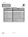
2.4 Periodic Repair Parts and Disposables
ATTENTION
Replace the periodic repair parts such as fan, battery, backup battery, HD, fuse, and display. If not
change the parts and past the periodic term, sudden traffic fault might lead to the whole system failure
and damaging. Replace the disposables such as ink ribbon, FD, recording paper, and headset.
We recommend you to make a contract for the maintenance service.
ND-71548 (E)
PRODUCT LIABILITY
PL- 9
Issue 2
PRODUCT LIABILITY
This page is for your notes.
PRODUCT LIABILITY
PL- 10
Issue 2
ND-71548 (E)
ND-71548 (E)
ISSUE 2
AUGUST, 2002
NEAX2400 IPX
Internet Protocol eXchange
Installation Manual
TABLE OF CONTENTS
CHAPTER 1 INTRODUCTION . . . . . . . . . . . . . . . . . . . . . . . . . . . . . . . . . . . . . . . . . . . . . . . . . . . . . . . . . .
1. GENERAL . . . . . . . . . . . . . . . . . . . . . . . . . . . . . . . . . . . . . . . . . . . . . . . . . . . . . . . . . . . . . . . . . . . . . .
2. HOW TO FOLLOW THE MANUAL . . . . . . . . . . . . . . . . . . . . . . . . . . . . . . . . . . . . . . . . . . . . . . . . . . .
2.1 Outline . . . . . . . . . . . . . . . . . . . . . . . . . . . . . . . . . . . . . . . . . . . . . . . . . . . . . . . . . . . . . . . . . . . . .
2.2 How to Follow NAPs . . . . . . . . . . . . . . . . . . . . . . . . . . . . . . . . . . . . . . . . . . . . . . . . . . . . . . . . . .
2.3 How To Follow Trees . . . . . . . . . . . . . . . . . . . . . . . . . . . . . . . . . . . . . . . . . . . . . . . . . . . . . . . . . .
2.4 Figure and Table Numbers . . . . . . . . . . . . . . . . . . . . . . . . . . . . . . . . . . . . . . . . . . . . . . . . . . . . .
2.5 Essential/Critical Information . . . . . . . . . . . . . . . . . . . . . . . . . . . . . . . . . . . . . . . . . . . . . . . . . . . .
Page
1
1
3
3
3
5
7
7
CHAPTER 2 INSTALLATION DESIGN . . . . . . . . . . . . . . . . . . . . . . . . . . . . . . . . . . . . . . . . . . . . . . . . . . . .
1. GENERAL . . . . . . . . . . . . . . . . . . . . . . . . . . . . . . . . . . . . . . . . . . . . . . . . . . . . . . . . . . . . . . . . . . . . . .
2. ENVIRONMENTAL REQUIREMENTS . . . . . . . . . . . . . . . . . . . . . . . . . . . . . . . . . . . . . . . . . . . . . . . .
2.1 Temperature And Humidity . . . . . . . . . . . . . . . . . . . . . . . . . . . . . . . . . . . . . . . . . . . . . . . . . . . . .
2.2 Heat Generation From Switching Equipment . . . . . . . . . . . . . . . . . . . . . . . . . . . . . . . . . . . . . . .
3. FLOOR SPACE . . . . . . . . . . . . . . . . . . . . . . . . . . . . . . . . . . . . . . . . . . . . . . . . . . . . . . . . . . . . . . . . . .
4. FLOOR LOAD REQUIREMENTS . . . . . . . . . . . . . . . . . . . . . . . . . . . . . . . . . . . . . . . . . . . . . . . . . . . .
5. EQUIPMENT ROOM REQUIREMENTS . . . . . . . . . . . . . . . . . . . . . . . . . . . . . . . . . . . . . . . . . . . . . . .
5.1 Floor Surface . . . . . . . . . . . . . . . . . . . . . . . . . . . . . . . . . . . . . . . . . . . . . . . . . . . . . . . . . . . . . . . .
5.2 Wall . . . . . . . . . . . . . . . . . . . . . . . . . . . . . . . . . . . . . . . . . . . . . . . . . . . . . . . . . . . . . . . . . . . . . . .
5.3 Ceiling . . . . . . . . . . . . . . . . . . . . . . . . . . . . . . . . . . . . . . . . . . . . . . . . . . . . . . . . . . . . . . . . . . . . .
5.4 Lighting Facilities . . . . . . . . . . . . . . . . . . . . . . . . . . . . . . . . . . . . . . . . . . . . . . . . . . . . . . . . . . . . .
6. POWER SUPPLY REQUIREMENTS . . . . . . . . . . . . . . . . . . . . . . . . . . . . . . . . . . . . . . . . . . . . . . . . .
6.1 Main Source Power . . . . . . . . . . . . . . . . . . . . . . . . . . . . . . . . . . . . . . . . . . . . . . . . . . . . . . . . . . .
6.2 Current Consumption . . . . . . . . . . . . . . . . . . . . . . . . . . . . . . . . . . . . . . . . . . . . . . . . . . . . . . . . .
6.3 Power Distribution Box Requirements . . . . . . . . . . . . . . . . . . . . . . . . . . . . . . . . . . . . . . . . . . . . .
6.4 Grounding . . . . . . . . . . . . . . . . . . . . . . . . . . . . . . . . . . . . . . . . . . . . . . . . . . . . . . . . . . . . . . . . . .
7. MDF REQUIREMENTS . . . . . . . . . . . . . . . . . . . . . . . . . . . . . . . . . . . . . . . . . . . . . . . . . . . . . . . . . . .
8. INSTALLATION TOOLS . . . . . . . . . . . . . . . . . . . . . . . . . . . . . . . . . . . . . . . . . . . . . . . . . . . . . . . . . . .
9. SYSTEM ACCOMMODATION . . . . . . . . . . . . . . . . . . . . . . . . . . . . . . . . . . . . . . . . . . . . . . . . . . . . . .
9.1 System Accommodation . . . . . . . . . . . . . . . . . . . . . . . . . . . . . . . . . . . . . . . . . . . . . . . . . . . . . . .
9.2 Circuit Card Locations . . . . . . . . . . . . . . . . . . . . . . . . . . . . . . . . . . . . . . . . . . . . . . . . . . . . . . . . .
9.3 Preparation of Trunking Diagram . . . . . . . . . . . . . . . . . . . . . . . . . . . . . . . . . . . . . . . . . . . . . . . .
9.4 Preparation of Module Group Face Layout And Port Accommodation Diagram . . . . . . . . . . . . .
9.5 Preparation of Circuit Card Switch Setting Sheets . . . . . . . . . . . . . . . . . . . . . . . . . . . . . . . . . . .
10. INSTALLATION CABLES . . . . . . . . . . . . . . . . . . . . . . . . . . . . . . . . . . . . . . . . . . . . . . . . . . . . . . . . . .
10.1 AC Input, DC Power, And Ground Cables . . . . . . . . . . . . . . . . . . . . . . . . . . . . . . . . . . . . . . . . . .
10.2 Cables Between The PBX And MDF . . . . . . . . . . . . . . . . . . . . . . . . . . . . . . . . . . . . . . . . . . . . . .
8
8
8
8
9
10
10
10
10
11
11
11
11
11
12
13
13
13
14
15
15
22
26
26
26
26
27
33
ND-71548 (E)
TABLE OF CONTENTS
Page i
Issue 2
TABLE OF CONTENTS (CONTINUED)
Page
CHAPTER 3 INSTALLATION PROCEDURE . . . . . . . . . . . . . . . . . . . . . . . . . . . . . . . . . . . . . . . . . . . . . . .
35
1. GENERAL . . . . . . . . . . . . . . . . . . . . . . . . . . . . . . . . . . . . . . . . . . . . . . . . . . . . . . . . . . . . . . . . . . . . . .
35
2. PRECAUTIONS BEFORE BEGINNING INSTALLATION . . . . . . . . . . . . . . . . . . . . . . . . . . . . . . . . . .
36
2.1 Outline . . . . . . . . . . . . . . . . . . . . . . . . . . . . . . . . . . . . . . . . . . . . . . . . . . . . . . . . . . . . . . . . . . . . .
36
3. INSTALLATION PROCEDURE . . . . . . . . . . . . . . . . . . . . . . . . . . . . . . . . . . . . . . . . . . . . . . . . . . . . . .
38
NAP-200-001
Installation Preparation . . . . . . . . . . . . . . . . . . . . . . . . . . . . . . . . . . . . . . . . . . . . . .
39
NAP-200-002
Marketing, Leveling, and Drilling . . . . . . . . . . . . . . . . . . . . . . . . . . . . . . . . . . . . . . .
41
1. WHEN SECURING THE PBX DIRECTLY ONTO THE FLOOR . . . . . . . . . . . . . . . . . . . . . . .
42
2. WHEN SECURING THE PBX WITH THE SPECIAL STAND . . . . . . . . . . . . . . . . . . . . . . . . .
45
3. WHEN SECURING PBX WITH FLOOR ELEVATIONS. . . . . . . . . . . . . . . . . . . . . . . . . . . . . .
47
4. MARKING, LEVELING AND DRILLING FOR MDF, POWER EQUIPMENT,
AND PERIPHERAL EQUIPMENT . . . . . . . . . . . . . . . . . . . . . . . . . . . . . . . . . . . . . . . . . . . . . .
48
NAP-200-003
Unpacking and Inspection . . . . . . . . . . . . . . . . . . . . . . . . . . . . . . . . . . . . . . . . . . . .
49
1. UNPACKING . . . . . . . . . . . . . . . . . . . . . . . . . . . . . . . . . . . . . . . . . . . . . . . . . . . . . . . . . . . . . .
49
2. INSPECTION . . . . . . . . . . . . . . . . . . . . . . . . . . . . . . . . . . . . . . . . . . . . . . . . . . . . . . . . . . . . . .
50
NAP-200-004
Installation of the Base Unit . . . . . . . . . . . . . . . . . . . . . . . . . . . . . . . . . . . . . . . . . .
51
1. INSTALLING THE BASE UNIT DIRECTLY ONTO THE FLOOR . . . . . . . . . . . . . . . . . . . . . .
51
2. INSTALLING THE BASE UNIT USING A SPECIAL STAND. . . . . . . . . . . . . . . . . . . . . . . . . .
53
NAP-200-005
Mounting of Units and Modules . . . . . . . . . . . . . . . . . . . . . . . . . . . . . . . . . . . . . . .
54
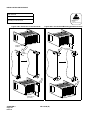
1. MOUNTING OF UNITS AND MODULES . . . . . . . . . . . . . . . . . . . . . . . . . . . . . . . . . . . . . . . .
54
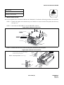
2. INSTALLATION OF FANU. . . . . . . . . . . . . . . . . . . . . . . . . . . . . . . . . . . . . . . . . . . . . . . . . . . .
55
3. PROCEDURE FOR FANU ON THE TOPU . . . . . . . . . . . . . . . . . . . . . . . . . . . . . . . . . . . . . . .
56
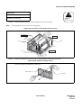
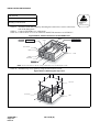
4. PROCEDURE FOR FANU IN THE FAN BOX . . . . . . . . . . . . . . . . . . . . . . . . . . . . . . . . . . . . .
61
5. ATTACHING THE ADDITIONAL NOISE FILTER UNIT (NFILU) TO THE BASEU . . . . . . . . .
67
NAP-200-006
Installation of Power Equipment . . . . . . . . . . . . . . . . . . . . . . . . . . . . . . . . . . . . . . .
70
NAP-200-007
Installation of the MDF . . . . . . . . . . . . . . . . . . . . . . . . . . . . . . . . . . . . . . . . . . . . . .
71
NAP-200-008
Connection of Power and Ground Cables from the Power Equipment . . . . . . . . . .
72
1. CONNECTION OF THE POWER AND GROUND CABLES . . . . . . . . . . . . . . . . . . . . . . . . . .
72
2. CONNECTION OF DC-DC CONVERTER FOR TELEPHONE SETS EQUIPPED
WITH MESSAGE WAITING LAMPS . . . . . . . . . . . . . . . . . . . . . . . . . . . . . . . . . . . . . . . . . . . .
76
3. END JOINTING OF POWER AND GROUND CABLES . . . . . . . . . . . . . . . . . . . . . . . . . . . . .
79
4. BRANCHING OF POWER CABLES . . . . . . . . . . . . . . . . . . . . . . . . . . . . . . . . . . . . . . . . . . . .
81
NAP-200-009
Setting of Switch Positions and Mounting of Circuit Cards . . . . . . . . . . . . . . . . . . .
85
1. PRECAUTIONS . . . . . . . . . . . . . . . . . . . . . . . . . . . . . . . . . . . . . . . . . . . . . . . . . . . . . . . . . . . .
85
2. EXTRACTION OF MOUNTED CIRCUIT CARDS . . . . . . . . . . . . . . . . . . . . . . . . . . . . . . . . . .
86
3. MOUNTING OF CIRCUIT CARDS . . . . . . . . . . . . . . . . . . . . . . . . . . . . . . . . . . . . . . . . . . . . .
88
4. SETTING OF SWITCH POSITIONS ON CIRCUIT CARDS . . . . . . . . . . . . . . . . . . . . . . . . . .
89
5. INSTALLATION OF CPR . . . . . . . . . . . . . . . . . . . . . . . . . . . . . . . . . . . . . . . . . . . . . . . . . . . . .
91
NAP-200-010
Internal Cable Connections . . . . . . . . . . . . . . . . . . . . . . . . . . . . . . . . . . . . . . . . . . .
98
NAP-200-011
Inter-Frame Cable Connections . . . . . . . . . . . . . . . . . . . . . . . . . . . . . . . . . . . . . . . 162
NAP-200-012
Front Cable Connections between Circuit Cards . . . . . . . . . . . . . . . . . . . . . . . . . . 186
NAP-200-013
Cable Running from the PBX to MDF, ATTCON, MAT, and SMDR . . . . . . . . . . . . 187
1. CABLE RUNNING FROM THE PBX TO THE MDF AND ATTCON . . . . . . . . . . . . . . . . . . . . 188
2. CABLE RUNNING FROM THE PBX TO THE MAT AND SMDR. . . . . . . . . . . . . . . . . . . . . . . 192
3. CONNECTIONS AT THE PBX SIDE . . . . . . . . . . . . . . . . . . . . . . . . . . . . . . . . . . . . . . . . . . . . 193
4. CABLE TYING AT THE PBX . . . . . . . . . . . . . . . . . . . . . . . . . . . . . . . . . . . . . . . . . . . . . . . . . . 193
5. TERMINATION OF THE CABLES BETWEEN THE PBX AND THE MDF OR ATTCON ONTO
THE CABLE SUPPORT ASSEMBLY . . . . . . . . . . . . . . . . . . . . . . . . . . . . . . . . . . . . . . . . . . . 195
NAP-200-014
Termination of Cables on MDF (Wire Accommodation of Each Cable) . . . . . . . . . 200
TABLE OF CONTENTS
Page ii
Issue 2
ND-71548 (E)
TABLE OF CONTENTS (CONTINUED)
Page
NAP-200-015
Cable Termination and Cross Connections from MDF to Peripheral Equipment, C. O.
Lines, and Tie Lines . . . . . . . . . . . . . . . . . . . . . . . . . . . . . . . . . . . . . . . . . . . . . . . . 201
1. CROSS CONNECTION OF STATIONS . . . . . . . . . . . . . . . . . . . . . . . . . . . . . . . . . . . . . . . . . 202
2. CROSS CONNECTION OF TRUNKS (C.O. LINES AND TIE LINES). . . . . . . . . . . . . . . . . . . 203
3. CROSS CONNECTIONS FOR PFT . . . . . . . . . . . . . . . . . . . . . . . . . . . . . . . . . . . . . . . . . . . . 205
4. CROSS CONNECTION OF ALARM INDICATING PANEL AND MUSIC ON HOLD. . . . . . . . 208
5. CROSS CONNECTIONS FOR TAS INDICATOR . . . . . . . . . . . . . . . . . . . . . . . . . . . . . . . . . . 213
6. CROSS CONNECTIONS FOR EXTERNAL SWITCHES . . . . . . . . . . . . . . . . . . . . . . . . . . . . 216
7. CONNECTION OF ANNOUNCEMENT MACHINE . . . . . . . . . . . . . . . . . . . . . . . . . . . . . . . . . 218
8. CONNECTION OF PAGING EQUIPMENT . . . . . . . . . . . . . . . . . . . . . . . . . . . . . . . . . . . . . . . 220
9. CROSS CONNECTIONS. . . . . . . . . . . . . . . . . . . . . . . . . . . . . . . . . . . . . . . . . . . . . . . . . . . . . 222
10. CROSS CONNECTIONS FOR DIGITAL INTERFACES . . . . . . . . . . . . . . . . . . . . . . . . . . . . . 226
NAP-200-016
Installation of the DESK CONSOLE and Cable Connection . . . . . . . . . . . . . . . . . . 233
1. CABLE CONNECTION DIAGRAM . . . . . . . . . . . . . . . . . . . . . . . . . . . . . . . . . . . . . . . . . . . . . 237
2. CALCULATION OF THE DISTANCE BETWEEN THE ATI CIRCUIT CARD AND MODULAR
ROSETTE . . . . . . . . . . . . . . . . . . . . . . . . . . . . . . . . . . . . . . . . . . . . . . . . . . . . . . . . . . . . . . . . 238
3. MOUNTING OF HEADSET (OPTIONAL) . . . . . . . . . . . . . . . . . . . . . . . . . . . . . . . . . . . . . . . . 241
4. MOUNTING OF HANDSET (OPTIONAL) . . . . . . . . . . . . . . . . . . . . . . . . . . . . . . . . . . . . . . . . 242
5. CONNECTION OF RECORDING EQUIPMENT . . . . . . . . . . . . . . . . . . . . . . . . . . . . . . . . . . . 248
6. 8-CORE LINE CABLE (INSTALLATION CABLE) . . . . . . . . . . . . . . . . . . . . . . . . . . . . . . . . . . 251
7. CONNECTION OF AC-DC ADAPTER (OPTIONAL) . . . . . . . . . . . . . . . . . . . . . . . . . . . . . . . . 252
8. MOUNTING OF ADD-ON CONSOLE (FOR HOTEL SYSTEM) . . . . . . . . . . . . . . . . . . . . . . . 253
9. MOUNTING OF ADD-ON CONSOLE . . . . . . . . . . . . . . . . . . . . . . . . . . . . . . . . . . . . . . . . . . . 256
10. CONNECTION OF AC-DC ADAPTER FOR ADD-ON CONSOLE (OPTIONAL). . . . . . . . . . . 260
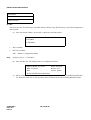
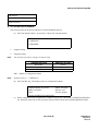
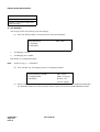
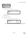
11. CONFIGURATION MENU . . . . . . . . . . . . . . . . . . . . . . . . . . . . . . . . . . . . . . . . . . . . . . . . . . . . 261
12. SELECTION OF CONFIGURATION ITEM . . . . . . . . . . . . . . . . . . . . . . . . . . . . . . . . . . . . . . . 264
13. ASSIGNMENT OF CONFIGURATION DATA . . . . . . . . . . . . . . . . . . . . . . . . . . . . . . . . . . . . . 265
14. HEADSET/HANDSET . . . . . . . . . . . . . . . . . . . . . . . . . . . . . . . . . . . . . . . . . . . . . . . . . . . . . . . 266
15. HEADSET TYPE . . . . . . . . . . . . . . . . . . . . . . . . . . . . . . . . . . . . . . . . . . . . . . . . . . . . . . . . . . . 267
16. MUTE . . . . . . . . . . . . . . . . . . . . . . . . . . . . . . . . . . . . . . . . . . . . . . . . . . . . . . . . . . . . . . . . . . . . 268
17. REC CONTROL . . . . . . . . . . . . . . . . . . . . . . . . . . . . . . . . . . . . . . . . . . . . . . . . . . . . . . . . . . . . 269
18. SUP CONNECTION. . . . . . . . . . . . . . . . . . . . . . . . . . . . . . . . . . . . . . . . . . . . . . . . . . . . . . . . . 270
19. REC VOLUME ADJUSTMENT . . . . . . . . . . . . . . . . . . . . . . . . . . . . . . . . . . . . . . . . . . . . . . . . 271
20. BLF. . . . . . . . . . . . . . . . . . . . . . . . . . . . . . . . . . . . . . . . . . . . . . . . . . . . . . . . . . . . . . . . . . . . . . 272
21. HOLD/START/RELEASE/SWAP . . . . . . . . . . . . . . . . . . . . . . . . . . . . . . . . . . . . . . . . . . . . . . . 273
22. 2ND RINGING . . . . . . . . . . . . . . . . . . . . . . . . . . . . . . . . . . . . . . . . . . . . . . . . . . . . . . . . . . . . . 274
23. RINGING . . . . . . . . . . . . . . . . . . . . . . . . . . . . . . . . . . . . . . . . . . . . . . . . . . . . . . . . . . . . . . . . . 275
24. UPDATING CONFIGURATION DATA. . . . . . . . . . . . . . . . . . . . . . . . . . . . . . . . . . . . . . . . . . . 276
NAP-200-017
Installation of Maintenance Administration Terminal (MAT) and Cable Connections 277
1. INSTALLATION OF MAT AND CABLE CONNECTIONS . . . . . . . . . . . . . . . . . . . . . . . . . . . . 277
2. INSTALLATION OF MAT AND CABLE CONNECTION BY USING MODEM . . . . . . . . . . . . . 280
3. INSTALLATION OF SYSTEM MESSAGE PRINTER AND CABLE CONNECTIONS . . . . . . . 282
NAP-200-018
Connections of SMDR . . . . . . . . . . . . . . . . . . . . . . . . . . . . . . . . . . . . . . . . . . . . . . 287
CHAPTER 4 SYSTEM STARTUP . . . . . . . . . . . . . . . . . . . . . . . . . . . . . . . . . . . . . . . . . . . . . . . . . . . . . . . .
1. GENERAL . . . . . . . . . . . . . . . . . . . . . . . . . . . . . . . . . . . . . . . . . . . . . . . . . . . . . . . . . . . . . . . . . . . . . .
2. PRECAUTIONS BEFORE BEGINNING SYSTEM STARTUP . . . . . . . . . . . . . . . . . . . . . . . . . . . . . .
3. SYSTEM STARTUP PROCEDURE . . . . . . . . . . . . . . . . . . . . . . . . . . . . . . . . . . . . . . . . . . . . . . . . . .
NAP-200-019
Power ON . . . . . . . . . . . . . . . . . . . . . . . . . . . . . . . . . . . . . . . . . . . . . . . . . . . . . . . .
ND-71548 (E)
291
291
291
294
295
TABLE OF CONTENTS
Page iii
Issue 2
TABLE OF CONTENTS (CONTINUED)
Page
NAP-200-020
NAP-200-021
NAP-200-022
NAP-200-023
Program Install and Load . . . . . . . . . . . . . . . . . . . . . . . . . . . . . . . . . . . . . . . . . . . .
Assignment of Office Data . . . . . . . . . . . . . . . . . . . . . . . . . . . . . . . . . . . . . . . . . . .
Check of Lamp Indications and System Messages . . . . . . . . . . . . . . . . . . . . . . . .
Check of Alarm Lamps of the TOPU . . . . . . . . . . . . . . . . . . . . . . . . . . . . . . . . . . . .
297
303
305
310
CHAPTER 5 INSTALLATION TEST PROCEDURE . . . . . . . . . . . . . . . . . . . . . . . . . . . . . . . . . . . . . . . . . .
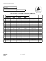
1. HOW TO ENTER DATA IN THE TEST CHECK COLUMN . . . . . . . . . . . . . . . . . . . . . . . . . . . . . . . .
2. BASIC CONNECTION TEST . . . . . . . . . . . . . . . . . . . . . . . . . . . . . . . . . . . . . . . . . . . . . . . . . . . . . . .
2.1 Outline . . . . . . . . . . . . . . . . . . . . . . . . . . . . . . . . . . . . . . . . . . . . . . . . . . . . . . . . . . . . . . . . . . . . .
2.2 Basic Connection Test Procedure . . . . . . . . . . . . . . . . . . . . . . . . . . . . . . . . . . . . . . . . . . . . . . . .
NAP-200-024
DT (Dial Tone) Connection Test . . . . . . . . . . . . . . . . . . . . . . . . . . . . . . . . . . . . . . .
NAP-200-025
Station to Station Connection Test . . . . . . . . . . . . . . . . . . . . . . . . . . . . . . . . . . . . .
3. SYSTEM INITIALIZED TEST . . . . . . . . . . . . . . . . . . . . . . . . . . . . . . . . . . . . . . . . . . . . . . . . . . . . . . .
3.1 Outline . . . . . . . . . . . . . . . . . . . . . . . . . . . . . . . . . . . . . . . . . . . . . . . . . . . . . . . . . . . . . . . . . . . . .
3.2 System Initialized Test Procedure . . . . . . . . . . . . . . . . . . . . . . . . . . . . . . . . . . . . . . . . . . . . . . . .
NAP-200-026
System Changeover Test . . . . . . . . . . . . . . . . . . . . . . . . . . . . . . . . . . . . . . . . . . . .
NAP-200-027
System Initialization Test . . . . . . . . . . . . . . . . . . . . . . . . . . . . . . . . . . . . . . . . . . . .
NAP-200-028
Circuit Card Initialization Test . . . . . . . . . . . . . . . . . . . . . . . . . . . . . . . . . . . . . . . . .
4. PORT CONNECTION TEST . . . . . . . . . . . . . . . . . . . . . . . . . . . . . . . . . . . . . . . . . . . . . . . . . . . . . . . .
4.1 Outline . . . . . . . . . . . . . . . . . . . . . . . . . . . . . . . . . . . . . . . . . . . . . . . . . . . . . . . . . . . . . . . . . . . . .
4.2 Port Connection Test Procedure . . . . . . . . . . . . . . . . . . . . . . . . . . . . . . . . . . . . . . . . . . . . . . . . .
NAP-200-029
ORT (RST Card) Connection Test . . . . . . . . . . . . . . . . . . . . . . . . . . . . . . . . . . . . .
NAP-200-030
ATTCON (ATI Card) Connection Test . . . . . . . . . . . . . . . . . . . . . . . . . . . . . . . . . .
NAP-200-031
Line (LC, ELC, DLC, Card) Connection Test . . . . . . . . . . . . . . . . . . . . . . . . . . . . .
NAP-200-032
Outgoing Trunk (COT, TLT, DTI Card) Connection Test . . . . . . . . . . . . . . . . . . . .
NAP-200-033
Incoming Trunk (COT, TLT, DTI Card)
Connection Test . . . . . . . . . . . . . . . . . . . . . . . . . . . . . . . . . . . . . . . . . . . . . . . . . . .
NAP-200-034
Direct-In Termination Trunk (COT Card)
Connection Test . . . . . . . . . . . . . . . . . . . . . . . . . . . . . . . . . . . . . . . . . . . . . . . . . . .
NAP-200-035
SND (RST Card) Connection Test . . . . . . . . . . . . . . . . . . . . . . . . . . . . . . . . . . . . .
NAP-200-036
3-party Conference Trunk Function Test . . . . . . . . . . . . . . . . . . . . . . . . . . . . . . . .
NAP-200-037
Connection Test-Announcement Trunk for Announcement Service . . . . . . . . . . . .
NAP-200-038
Connection Test-Digital Announcement Trunk for Announcement Service . . . . . .
NAP-200-039
Connection Test-Paging Trunk for Paging Access Service . . . . . . . . . . . . . . . . . .
NAP-200-040
Connection Test-Paging Trunk for Paging Transfer Service . . . . . . . . . . . . . . . . .
NAP-200-041
Radio Paging Trunk (COT Card) Connection Test . . . . . . . . . . . . . . . . . . . . . . . . .
NAP-200-042
Howler & Ringing Signal Test . . . . . . . . . . . . . . . . . . . . . . . . . . . . . . . . . . . . . . . . .
5. OVERALL TEST . . . . . . . . . . . . . . . . . . . . . . . . . . . . . . . . . . . . . . . . . . . . . . . . . . . . . . . . . . . . . . . . .
5.1 Outline . . . . . . . . . . . . . . . . . . . . . . . . . . . . . . . . . . . . . . . . . . . . . . . . . . . . . . . . . . . . . . . . . . . . .
5.2 Overall Test Procedure . . . . . . . . . . . . . . . . . . . . . . . . . . . . . . . . . . . . . . . . . . . . . . . . . . . . . . . .
NAP-200-043
Overall Test for C.O. Line Outgoing Call . . . . . . . . . . . . . . . . . . . . . . . . . . . . . . . .
NAP-200-044
Overall Test for C.O. Line Incoming Call . . . . . . . . . . . . . . . . . . . . . . . . . . . . . . . .
NAP-200-045
Overall Test of CCIS Tie Line Outgoing Call . . . . . . . . . . . . . . . . . . . . . . . . . . . . .
NAP-200-046
Overall Test of CCIS Tie Line Incoming Call . . . . . . . . . . . . . . . . . . . . . . . . . . . . .
NAP-200-047
Test of Connection and Alternate Routing to All Tie Lines . . . . . . . . . . . . . . . . . . .
NAP-200-048
Test of Tandem Connection to Tie Line . . . . . . . . . . . . . . . . . . . . . . . . . . . . . . . . .
NAP-200-049
PAD Setting . . . . . . . . . . . . . . . . . . . . . . . . . . . . . . . . . . . . . . . . . . . . . . . . . . . . . .
6. IP CONNECTION TEST . . . . . . . . . . . . . . . . . . . . . . . . . . . . . . . . . . . . . . . . . . . . . . . . . . . . . . . . . . .
312
312
314
314
314
315
316
317
317
317
318
326
328
329
329
329
330
332
333
334
TABLE OF CONTENTS
Page iv
Issue 2
ND-71548 (E)
337
339
340
341
342
343
344
345
347
348
350
350
350
351
352
353
355
356
358
360
362
TABLE OF CONTENTS (CONTINUED)
Page
6.1 Outline . . . . . . . . . . . . . . . . . . . . . . . . . . . . . . . . . . . . . . . . . . . . . . . . . . . . . . . . . . . . . . . . . . . . . 362
6.2 IP Connection Test Procedure . . . . . . . . . . . . . . . . . . . . . . . . . . . . . . . . . . . . . . . . . . . . . . . . . . . 362
NAP-200-050
IP PAD Connection Test . . . . . . . . . . . . . . . . . . . . . . . . . . . . . . . . . . . . . . . . . . . . . 363
NAP-200-051
IPTRK (IP Trunk Card for FCCS) Connection Test . . . . . . . . . . . . . . . . . . . . . . . . 366
NAP-200-052
IPTRK (IP Trunk Card for CCIS) Connection Test . . . . . . . . . . . . . . . . . . . . . . . . . 369
NAP-200-053
IPTRK (IP Trunk Card for H.323) Connection Test . . . . . . . . . . . . . . . . . . . . . . . . . 372
NAP-200-054
PHA Connection Test . . . . . . . . . . . . . . . . . . . . . . . . . . . . . . . . . . . . . . . . . . . . . . . 375
NAP-200-055
PHD Connection Test . . . . . . . . . . . . . . . . . . . . . . . . . . . . . . . . . . . . . . . . . . . . . . . 377
NAP-200-056
PHC Connection Test . . . . . . . . . . . . . . . . . . . . . . . . . . . . . . . . . . . . . . . . . . . . . . . 380
CHAPTER 6 FAULT RECOVERY DURING TESTS . . . . . . . . . . . . . . . . . . . . . . . . . . . . . . . . . . . . . . . . . . 383
1. GENERAL . . . . . . . . . . . . . . . . . . . . . . . . . . . . . . . . . . . . . . . . . . . . . . . . . . . . . . . . . . . . . . . . . . . . . . 383
2. OUTLINE OF PROCEDURE FOR FAULT RECOVERY . . . . . . . . . . . . . . . . . . . . . . . . . . . . . . . . . . 383
NAP-200-057
Abnormal Lamp Indications After System Startup . . . . . . . . . . . . . . . . . . . . . . . . . 384
NAP-200-058
DT (Dial Tone) Connection Fault . . . . . . . . . . . . . . . . . . . . . . . . . . . . . . . . . . . . . . 386
NAP-200-059
Station to Station Connection Fault . . . . . . . . . . . . . . . . . . . . . . . . . . . . . . . . . . . . 387
CHAPTER 7 WORK AFTER INSTALLATION TESTS . . . . . . . . . . . . . . . . . . . . . . . . . . . . . . . . . . . . . . . . .
1. OFFICE DATA MANAGEMENT . . . . . . . . . . . . . . . . . . . . . . . . . . . . . . . . . . . . . . . . . . . . . . . . . . . . .
1.1 Preservation of Office Data . . . . . . . . . . . . . . . . . . . . . . . . . . . . . . . . . . . . . . . . . . . . . . . . . . . . .
2. PREPARATION OF TEST RESULT REPORT . . . . . . . . . . . . . . . . . . . . . . . . . . . . . . . . . . . . . . . . . .
3. MOUNTING OF THE FRONT AND REAR COVERS . . . . . . . . . . . . . . . . . . . . . . . . . . . . . . . . . . . . .
4. ATTACHMENT OF INTER-FRAME BRACKETS . . . . . . . . . . . . . . . . . . . . . . . . . . . . . . . . . . . . . . . .
5. SITE CLEANING . . . . . . . . . . . . . . . . . . . . . . . . . . . . . . . . . . . . . . . . . . . . . . . . . . . . . . . . . . . . . . . . .
ND-71548 (E)
389
389
389
390
390
400
404
TABLE OF CONTENTS
Page v
Issue 2
This page is for your notes.
TABLE OF CONTENTS
Page vi
Issue 2
ND-71548 (E)
INTRODUCTION
CHAPTER 1
INTRODUCTION
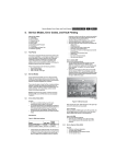
1. GENERAL
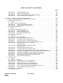
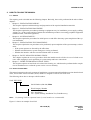
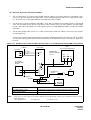
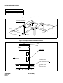
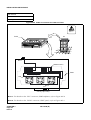
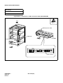
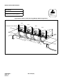
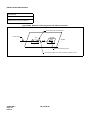
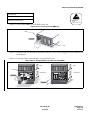
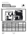
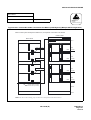
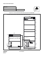
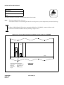
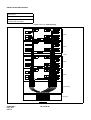
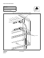
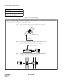
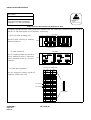
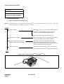
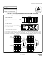
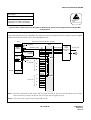
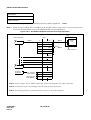
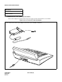
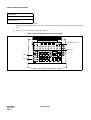
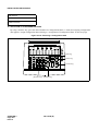
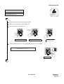
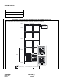
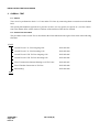
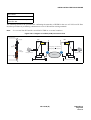
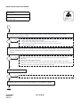
The figure below shows the outer view of the NEAX2400 IPX-referred to in the remainder of this manual as
“the system.” During the period from equipment carry-in of the system till it is placed in service, the following
must be performed:
•
Installation of the system and its peripheral equipment
•
System startup
•
Installation test
•
Miscellaneous jobs
This manual explains how to proceed with these activities and related precaution. It is recommended that the
installer thoroughly read Section 2., “HOW TO FOLLOW THE MANUAL” before engaging in any phase of
the installation.
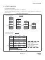
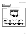
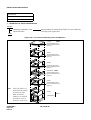
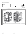
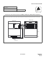
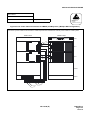
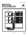
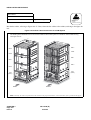
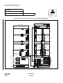
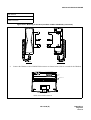
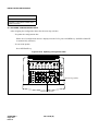
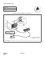
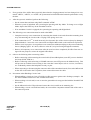
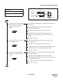
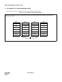
Figure 1-1 NEAX2400 IPX Outer View
This figure shows the outer view of the fully expanded system.
<Multiple IMG Configuration>
<Single IMG Configuration>
IMG3
IMG2
IMG1
TOPU
PIM3
NEC
IMG0
NEC
NEC
NEC
TOPU
NEC
PIM3
PIM2
PIM2
FANU
FANU
PIM1
PIM1
PIM0
1
SYSTEM SELECT 0
PIM0
3
SYSTEM SELECT 1
MBR
SYSTEM SELECT 2
LPM (MGC)
SLOT NO.
1
SYSTEM SELECT 0
0
1
2
3
4
5
6
0
1
2
3
4
5
6
3
SYSTEM SELECT 1
MBR
SLOT NO.
1
SYSTEM SELECT 0
3
SYSTEM SELECT 1
LPM (MGC)
MBR
SYSTEM SELECT 2
SLOT NO.
1
SYSTEM SELECT 0
0
1
2
3
4
5
6
0
1
2
3
4
5
6
3
SYSTEM SELECT 1
MBR
SLOT NO.
MGC: Media Gateway Controller
LPM: Local Processor Module
PIM: Port Interface Module
TOPU: Top Unit
BASEU: Base Unit
FANU: Fan Unit
ND-71548 (E)
CHAPTER 1
Page 1
Issue 2
INTRODUCTION
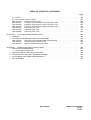
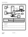
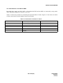
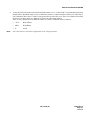
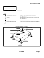
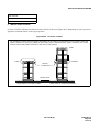
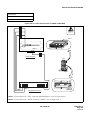
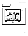
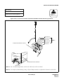
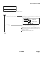
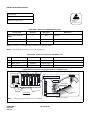
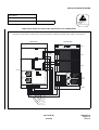
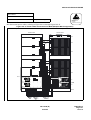
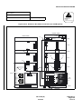
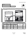
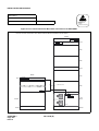
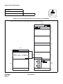
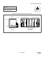
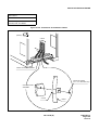
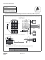
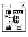
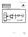
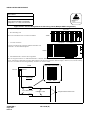
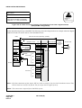
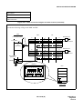
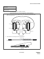
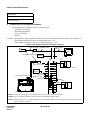
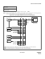
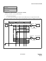
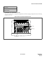
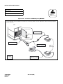
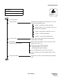
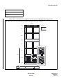
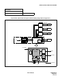
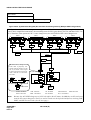
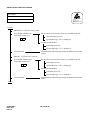
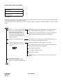
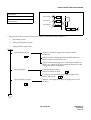
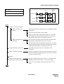
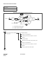
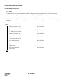
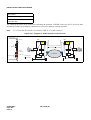
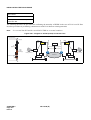
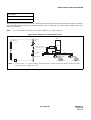
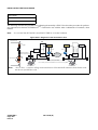
The figure below shows an example of the system configuration of NEAX2400 IPX.
PHA
: Handles control signals sent to/from an analog terminal connected to Analog Media Converter.
PHD
: Handles control signals sent to/from IP terminals such as DtermIP INASET and Dterm SP20.
PHC
: Sends/receives CCIS control signal from/to IP network.
IP PAD : Provides interface function between terminals/devices on LAN and conventional network
such as PSTN, ISDN, and private network.
Figure 1-2 System Configuration (Example)
Dterm Series E/Dterm75
PSTN/
Private Network
NEAX2400 IPX
Analog Terminal
ELC
VDSL
adapter
Analog
Terminal
NEC
NEC
COT/
TLT
LC
PHC
concentrator
PC
VDSL CONCENTRATOR
VC500T
LC with
splitter
IPTRK
PHA
PHC
MGC
Dterm Series i / D term IP
NEC
SYSTEM SELECT 0
3
1
3
PHD
SLOT NO.
SYSTEM SELECT 0
D term
1
SYSTEM SELECT 1
IP
SYSTEM SELECT 1
6
1
2
3
4
5
Recall
6
7
Feature
8
Conf
9
0
r
Director
Mic
Redial
#
Speake
y
Messag
e
Answer
Transfer
Speake
r
IP PAD
DtermIP INASET
controlled by PHD
CCIS No.7
Home
Home
1
4
2
3
Enter
6
5
7
8
9
*
0
#
IP Enabled Dterm
Dterm SP20
controlled by PHA
CHAPTER 1
Page 2
Issue 2
IP Network
MGC: Media Gateway Controller
MC: Media Converter
ELC: Electric Line Circuit
LC: Line Circuit
PHA: Protocol Handler for Analog MC
PHD: Protocol Handler for IP Enabled Dterm
PHC: Protocol Handler for CCIS
Analog MC
ON
Tx/Rx
PWR LINE -OPERATION-
0
LINK
100M
1
MC-2A
Analog Terminals
ND-71548 (E)
07/31/02
INTRODUCTION
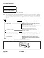
2. HOW TO FOLLOW THE MANUAL
2.1 Outline
The requiring work is divided into the following chapters. Basically, the work is performed in the order of these
chapters:
•
Chapter 2, “INSTALLATION DESIGN”
This chapter explains installation design and preparation of the required installation materials.
•
Chapter 3, “INSTALLATION PROCEDURE”
This chapter explains the procedures pertaining to equipment carry-in, installation, power supply (cabling,
wiring), etc., of the system, and also explains the installation procedures concerning peripheral equipment
(MDF, Rectifier, Terminal Equipment.).
•
Chapter 4, “SYSTEM STARTUP”
This chapter explains the procedures for initial power-on and office data entry upon completion of the system installation.
•
Chapter 5, “INSTALLATION TEST PROCEDURE”
This chapter explains the test procedures to be performed, upon completion of the system startup, to determine:
• If the system operates as directed by the office data.
• Whether reinitialization or system changeover can be performed.
• Whether the interface with the associated distant office is normal.
•
Chapter 6, “FAULT RECOVERY DURING TESTS”
This chapter explains the recovery procedure which the installer needs to follow in case of a fault occurrence while engaging in work pertaining to system startup and basic connections.
•
Chapter 7, “WORK AFTER INSTALLATION TESTS”
This chapter explains various kinds of work and site cleaning, etc. which must be performed after completion of installation tests so that the system can be cut over normally.
2.2 How to Follow NAPs
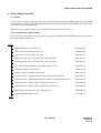
This manual categorizes the work contents of installation, system startup and installation tests into detailed work
items, and an NEC Action Procedure (NAP) number is assigned to each of such work item.
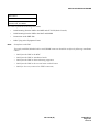
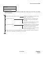
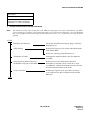
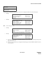
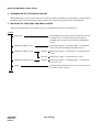
The following shows how to interpret a NAP number.
NAP- XXX-XXX
Serial Number (000-999) Note
Work Category Number
200: Installation
215: System Startup, Installation Test, Fault Recovery
Note:
Performing NAPs in sequential order by serial numbers is recommended.
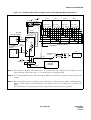
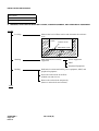
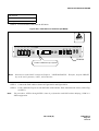
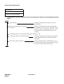
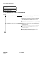
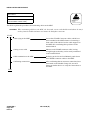
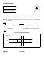
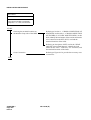
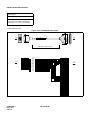
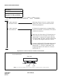
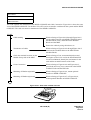
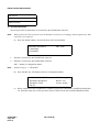
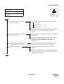
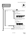
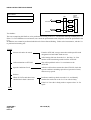
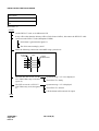
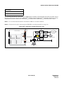
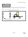
Figure 1-3 shows an example of an NAP.
ND-71548 (E)
CHAPTER 1
Page 3
Issue 2
INTRODUCTION
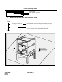
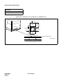
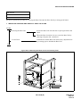
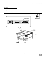
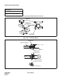
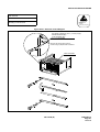
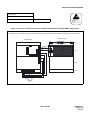
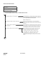
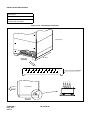
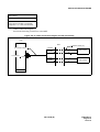
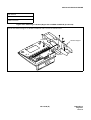
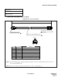
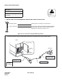
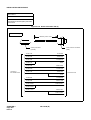
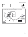
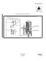
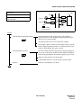
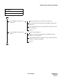
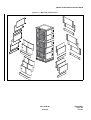
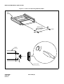
Figure 1-3 Example of NAP
NAP Number
Sheet Number of NAP
Title of NAP
NAP- 200-004
Sheet 3/3
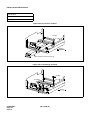
Installation of the Base Unit
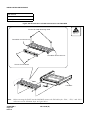
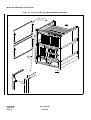
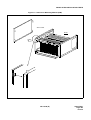
1.
INSTALLING THE BASE UNIT USING A SPECIAL STAND
START
Securing the Base Unit
Secure the Base Unit onto the special stand as per Figure
004-4.
Level Check
Check the level of the Base Unit. If necessary, adjust the
level by inserting spacers beneath the Base Unit.
END
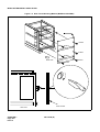
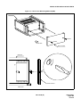
BASE U
BOLT (M-10)
LOCK WASHER
PLAIN WASHER
SPECIAL STAND
CHAPTER 1
Page 4
Issue 2
ND-71548 (E)
INTRODUCTION
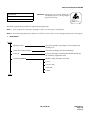
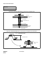
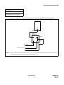
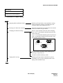
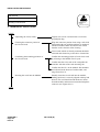
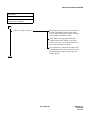
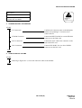
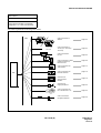
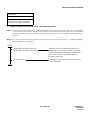
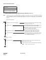
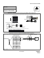
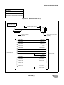
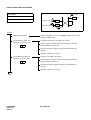
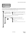
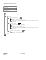
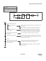
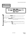
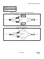
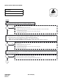
2.3 How To Follow Trees
This manual explains performance of a predetermined procedure (work contents covered in each NAP) in a
“Tree” format as shown in Figure 1-4. Before engaging in the intended work, be sure to understand the work
contents by tracing the given tree.
Figure 1-4 Example of a Tree
START
On the MDF, make temporary cross connections between the Trunk for Direct-In Termination (DIT)
and an LC.
C.O. Line Incoming Call
Station B dials the number of LC C (Station C).
Incoming Call to Station via
DIT Trunk
The call terminates to Station A; Station A rings.
Confirm that the ringing is distinct from that of an intraoffice call or ordinary C.O. call.
• The ringing signal for Direct-In Termination calls can
be the same as that used for C.O. calls if the related
Office Data is assigned.
System Data SYS1, INDEX 72, SYS3, INDEX 0, and
parameter DR of Command “ARTD”.
Answer and Talk
Station A goes off-hook.
Station A and B talk with each other.
Release
Station A and B both go on-hook.
Remove the temporary cross connections.
END
ND-71548 (E)
CHAPTER 1
Page 5
Issue 2
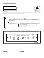
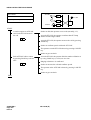
INTRODUCTION
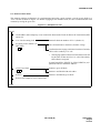
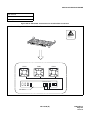
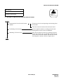
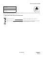
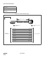
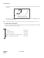
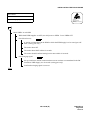
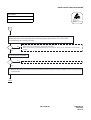
Figure 1-5 Static Caution Indication
ATTENTION
Contents
Static Sensitive
Handling
Precautions Required
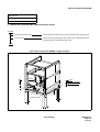
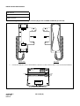
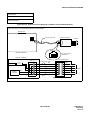
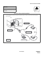
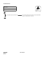
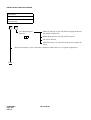
This manual provides “Static Caution” indicators (see Figure 1-5) on pages where work involving static-sensitive components is described.
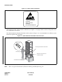
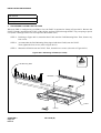
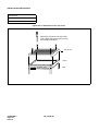
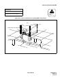
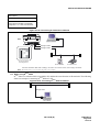
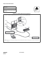
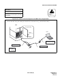
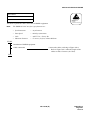
The 3M Model 8012 Portable Field Service Kit, shown in Figure 1-6, is recommended as an effective countermeasure against static electricity.
Figure 1-6 3M Model 8012 Portable Field Service Kit
wrist strap
Connect ground wire to the frame.
wrist strap
Place the circuit card on a
conductive sheet.
conductive sheet
Note:
3M is a registered trademark of Minnesota Mining and Manufacturing, Inc.
CHAPTER 1
Page 6
Issue 2
ND-71548 (E)
07/31/02
INTRODUCTION
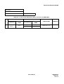
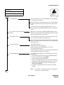
2.4 Figure and Table Numbers
Each Figure and Table within this manual are numbered as shown below.
1.
Figure and table in NAP
Figure XXX-X
Serial number of Figures in each NAP
Serial number (000-999) of the NAP in which the Figure exists.
2.
Other figure and table
Table X-X
Serial number of Table in each Chapter
Number of the Chapter in which the Table exists.
Understanding this numbering rule will help you when looking for the desired Figure or Table.
2.5 Essential/Critical Information
To prevent accidents or equipment damage from occurring while work is being performed, each manual provides WARNING, CAUTION, and Note: indications to draw the technician’s attention to specific matters.
1.
Note:
2.
Meaning
WARNING:
Personal injury may result if the warning is not heeded.
CAUTION:
Damage to the equipment and/or the system may result if the caution is not heeded.
Indicates an item which requires special attention.
Locations of Indicators
WARNING and CAUTION indications are located at the top of the page. Notes are included as part of the
work procedures on the page.
ND-71548 (E)
CHAPTER 1
Page 7
Issue 2
INSTALLATION DESIGN
CHAPTER 2
INSTALLATION DESIGN
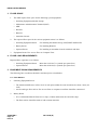
1. GENERAL
This chapter provides information pertaining to installation design and preparation of the required installation
materials. The following topics are discussed:
•
Environmental Requirements
•
Floor Space
•
Floor Load Requirements
•
Equipment Room Requirements
•
Power Supply Requirements
•
MDF Requirements
•
Installation Tools
•
System Accommodation
•
Installation Cables
2. ENVIRONMENTAL REQUIREMENTS
The PBX is sensitive to the same rises in temperature and humidity as a computer. Air conditioning may be required, depending on the installation environment. The following paragraphs address the following environmental conditions.
•
Temperature and Humidity
•
Heat Generation from Switching Equipment
2.1 Temperature And Humidity
Table 2-1 shows the environmental conditions required in the switching equipment room.
If the switching system is operated in an environment that does not meet these specifications, the reliability of
the switching equipment may be impaired. Improper operating conditions can cause circuit boards, etc., to deteriorate. Therefore, to enable the equipment to operate for the extent of its expected lifetime, careful consideration must be given to the location of the equipment, and to proper ventilation and air conditioning.
If no equipment is provided to remove the heat generated by the system, or if the temperature or humidity fluctuates repeatedly, the system’s electronic parts can be adversely affected. Such conditions will promote corrosion of metal parts and deterioration of insulation, thereby lowering the overall reliability of the system.
CHAPTER 2
Page 8
Issue 2
ND-71548 (E)
INSTALLATION DESIGN
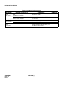
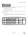
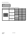
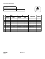
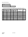
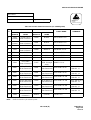
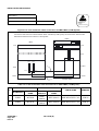
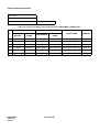
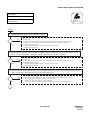
Table 2-1 Temperature and Humidity
During
Operations
TEMPERATURE
RELATIVE
HUMIDITY
Normal Operations
5°C - 30°C (41°F -86°F)
15% - 65%
Short Period Note
0°C - 40°C (32°F-104°F)
15% - 90%
–18°C - 50°C (0°F -122°F)
8% - 90%
Max. 5°C/30 Min. (9°F/30 Min.)
90%
During Storage & In Transit
Temperature Change
Note:
REMARKS
A short period means a period not exceeding three consecutive days (72 hours) or 15 days (360 hours) in
a year.
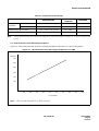
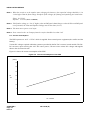
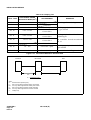
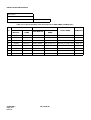
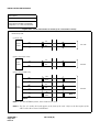
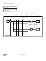
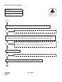
2.2 Heat Generation From Switching Equipment
Figure 2-1 shows heat generation from the switching equipment with respect to current consumption.
Figure 2-1 Heat Generation from Switching Equipment for the PBX
BTU/hour
3.5K
3.0K
2.5K
2.0K
1.5K
1.0K
100
200
300
400
500
600
700
800
900
1000
No. of PORTS
Note:
BTU; British Thermal Unit (1 BTU=1058.4J)
ND-71548 (E)
CHAPTER 2
Page 9
Issue 2
INSTALLATION DESIGN
3. FLOOR SPACE
1.
The PBX requires floor space for the following system equipment:
• Switching Equipment (Module Group)
• Maintenance Administration Terminal (MAT)
• MDF
• Rectifier
• Batteries
• Attendant Console
2.
3.
The required floor space for the various equipment rooms is as follows.
• Switching Equipment Room:
For installing the Module Group, MAT, MDF and Rectifier
• Battery Room:
For installing Batteries
• Operator Room:
For installing an Attendant Console with desk and chair
Equipment Room: Free Access Floor or Computer Floor
4. FLOOR LOAD REQUIREMENTS
Required floor capacities are as follows:
• Switching Equipment Room:
More than 3430 Pa (71.6 pounds per square foot)
• Operator Room:
More than 2940 Pa (61.4 pounds per square foot)
5. EQUIPMENT ROOM REQUIREMENTS
The following floor conditions should be considered prior to installation:
5.1 Floor Surface
1.
Switching Equipment Room
• The maximum difference in floor level at each point within the room should be less than +5mm (0.2
inch).
• An elevated-type floor such as Free Access floor or computer room floor should be constructed.
2.
Battery Room
• It is recommended that the floor have a slope (1/1000) and drain at the end of the slope.
• The floor surface should be made of acid-resistant materials.
CHAPTER 2
Page 10
Issue 2
ND-71548 (E)
INSTALLATION DESIGN
5.2 Wall
Switching Equipment Room
• A concrete wall is necessary so that cable racks can be installed (unless a free-access floor is used).
• It is recommended that the walls be painted so that the wall materials do not generate dust, etc.
• The maximum difference in level at the wall surface should be less than +5 mm (0.2 inch).
5.3 Ceiling
Switching Equipment Room
• The required ceiling height is more than 2.3 meters (7.5 feet).
5.4 Lighting Facilities
1.
Switching Equipment Room
• Fluorescent lamps are recommended.
• No less than 200 lux at the floor level is necessary.
2.
Operator Room
• Fluorescent lamps are recommended.
• No less than 200 lux at the floor level is necessary.
3.
Battery Room
• Anti-explosion type lamps must be utilized.
• No less than 150 lux at the floor level is necessary.
6. POWER SUPPLY REQUIREMENTS
6.1 Main Source Power
The PBX requires an operating power of -48 V DC ±5V DC. This DC operating power is supplied from the rectifier which receives AC power from the commercial AC power source. For greater system reliability, it is recommended that the PBX be supplied with backup DC operating power for a predetermined duration from the
batteries installed as the auxiliary power supply source.
The batteries for the PBX must be connected in parallel with the -48 V DC output of the rectifier. Also, when
installing batteries, an EMF panel must be placed in-line (series) with the input -48 V DC supplied to the PBX.
This panel is necessary when changing the state of the rectifier from float to equalize and vice versa.
ND-71548 (E)
CHAPTER 2
Page 11
Issue 2
INSTALLATION DESIGN
Note 1: When the rectifier is in the equalize state (charging the batteries), the output DC voltage should be 1.5 to
2 volts higher than the float voltage. Examples of the voltages for floating and equalizing are listed below:
Float: 50.5 V DC
Equalize: 52 V DC (Refer to Note 2.)
Note 2: The Equalize voltage is 1.5 to 2 V higher when an EMF panel (Diode Drop) is utilized. When an EMF panel
is not provided, the Float and Equalize Voltage must be the same (50.5 V).
Note 3: The main source power is AC input.
Note 4: Noise caused in the -48 V output from the rectifier should be less than 5 mV.
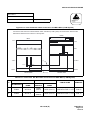
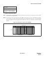
6.2 Current Consumption
The PBX operates on -48 V ±5 V DC which is supplied from external power equipment (the rectifier and the
battery).
Various DC voltages required within the system are provided by the DC-DC converter in each module. The DCDC converter, upon receiving the -48 V DC source power, converts it into various DC voltages and supplies
them to the associated circuits.
Figure 2-2 shows the current consumption of the PBX.
Figure 2-2 Current Consumption of the PBX
(AMPS)
35
30
25
DC
-48V
20
15
10
5
100
200
300
400
500
600
No. of PORTS
CHAPTER 2
Page 12
Issue 2
ND-71548 (E)
700
800
900
1000
INSTALLATION DESIGN
6.3 Power Distribution Box Requirements
The Power Distribution Box (PDB) should be installed with the following considerations:
1.
The AC power source service outlet and the fuse for the junction box should be provided independently of
any equipment other than the switching equipment.
2.
A warning notice should be attached to be PDB circuit breaker so that it will not be turned off accidentally.
3.
The Power Distribution Box should be installed at a location that is easy to reach.
4.
The Power Distribution Box should be installed at a location where the connecting cables extending to the
switching equipment will not be broken accidentally.
5.
The PDB cables should be run in such a way that they do not hamper the technician performing the installation.
6.
The Personal Computer (MAT) must have a separate AC service outlet.
6.4 Grounding
System grounding must have a specific ground resistance and AC noise level and is to be connected to a predetermined terminal in the PBX.
Standard grounding requirements are shown below.
•
Communication grounding:
Less than 1 ohm
•
Security ground for Module Group:
Less than 1 ohm
•
Grounding for the line protector of the MDF:
Less than 1 ohm
Note:
The AC ripple of various types of grounding should be less than 1/2 V-pp.
7. MDF REQUIREMENTS
Either a self-standing or wall-mounted type MDF can be used. The MDF must be equipped with the following
types of terminal blocks.
•
Arrester board for C.O. lines and external lines
•
Test spring terminals for localization tests
•
Local Block terminals
The number of terminals is to be determined according to the circuit configuration of the PBX and the number
of local lines.
ND-71548 (E)
CHAPTER 2
Page 13
Issue 2
INSTALLATION DESIGN
8. INSTALLATION TOOLS
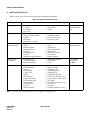
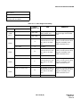
Table 2-2 shows the tools used in a typical NEAX2400 IPX installation.
Table 2-2 Typical Installation Tools
FUNCTION
TOOLS
PURPOSE
Marking
•
•
•
•
Steel Tape Measure
L-Square
Iron Square
Iron Level
• Center Punch
• Step Ladder
• Scriber
For Leveling and
Marking Plumb
Line
Drilling
•
•
•
•
•
Electric Drill
Electric Vibration Drill
Hammer
Point Drill
Drill Bit for Concrete
•
•
•
•
Concrete Chisel
Drill Bit for Metal
Power Cable Drum
Extension Cable
Drilling
Module Group and • Plump Bob
Rack Installation
• Jigsaw
• Hacksaw Frame
• Hacksaw Blade
• Flat File
• Half Round File
• Set File
• Adjustable Angle Wrench
•
•
•
•
•
•
•
•
Frame Cart
Cutter
Set Wrench
Socket Wrench Set
Step Ladder
Phillips Screwdriver
Screwdriver
Plastic Hammer
Module Group and
Rack Installation
Power Cable
Installation
• Clamping Tool
(for End Terminal,
Branch Terminal)
• Phillips Screwdriver
• Screwdriver
• Cutter
Miscellaneous
•
•
•
•
•
•
•
•
•
•
•
•
•
•
•
•
•
•
•
•
•
•
•
•
•
•
Note:
Circuit Tester
Pocket Measure
Scissors
Wire Clipper
Cable Cutter
Nipper
Wire Stripper
Round Nose Pliers
Non-Metallic Stick
Solder-Helper
Solder Sucker
IC Clip
Mini Test Probe
Telephone Set
Working Lamp
Wrapping Tool
Unwrapping Tool
Soldering Iron
Soldering Iron Stand
Connector Clamping Tool
Logic Checker and Counter
Pen Light
Precision Screwdriver (+)(-)
IC Buzzer
Tweezers
Portable Field Service Kit
For selection of Clamping Tool, refer to Tables 2-8 through 2-10.
CHAPTER 2
Page 14
Issue 2
ND-71548 (E)
Power Cable
Installation
See Note.
INSTALLATION DESIGN
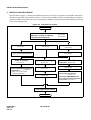
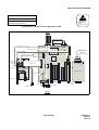
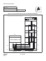
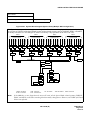
9. SYSTEM ACCOMMODATION
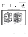
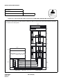
9.1 System Accommodation
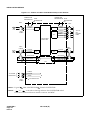
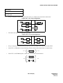
Module Group Configuration and Conditions for Configuration
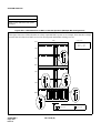
The module group configuration of the PBX is shown in Figure 2-3, and the conditions for configuration are
shown in Table 2-3.
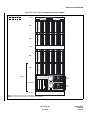
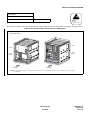
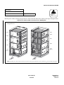
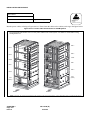
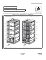
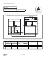
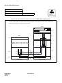
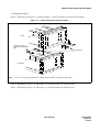
Figure 2-3 System Configuration
Single IMG Configuration
4-PIM
TOPU
BSCM
PIM3
3-PIM
TOPU
PIM2
PIM2
FANU
FANU
2-PIM
TOPU
PIM1
PIM1
PIM1
PIM0
PIM0
PIM0
LPM (MGC)
BSCM
LPM (MGC)
BSCM
LPM (MGC)
1-PIM
TOPU
PIM0
BSCM
LPM (MGC)
BASEU
BASEU
BASEU
BASEU
max. 1536 ports
(2048 time slots)
max. 1152 ports
(1536 time slots)
max. 768 ports
(1024 time slots)
max. 384 ports
(512 time slots)
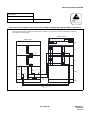
Multiple IMG Configuration
(Fully Expanded System)
BSCM
FRONT VIEW
FRONT VIEW
IMG0
IMG1
IMG2
IMG3
TOPU
TOPU
TOPU
TOPU
PIM3
PIM3
PIM3
PIM3
PIM2
PIM2
PIM2
PIM2
FANU
FANU
FANU
FANU
PIM1
PIM1
PIM1
PIM1
PIM0
PIM0
PIM0
PIM0
LPM (MGC)
TSWM
DUMMY
DUMMY
BASEU
BASEU
BASEU
BASEU
TOPU : Top Unit
PIM : Port Interface Module
FANU : Fan Unit
LPM : Local Processor Module
MGC : Media Gateway Controller
BASEU : Base Unit
BSCM : Basic Control Module
max. 3072 ports
max. 4608 ports
max. 6144 ports
(8192 time slots)
ND-71548 (E)
CHAPTER 2
Page 15
Issue 2
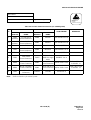
INSTALLATION DESIGN
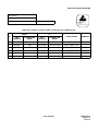
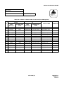
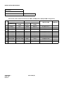
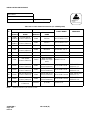
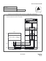
Table 2-3 Conditions for Configuration
UNIT NAME
FANU
(Fan Unit)
2nd NFILU
(Noise Filter)
NUMBER OF MODULES
PIM
Less than two modules
Mounted in TOPU
PIM
Three or more modules
Mounted in between the 2nd PIM and
the 3rd PIM
Less than two modules
Not required
Three or more modules
Mounted in BASEU
TOPU
(Top Unit)
Note:
CONDITIONS
Equipped with PZ-DK222 (KEY) and
PZ-DK223 (DSP) Cards
A NFILU is mounted in BASEU.
CHAPTER 2
Page 16
Issue 2
ND-71548 (E)
REMARKS
Note
INSTALLATION DESIGN
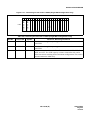
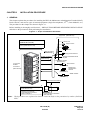
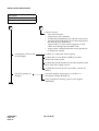
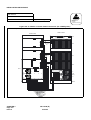
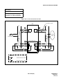
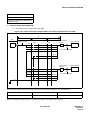
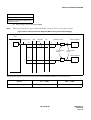
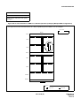
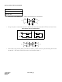
Figure 2-4 Time Slot, Group Number Assignment
Time Slots are allocated for a PIM as shown below:
Slot No.
00 02 04 05 06 07 08 09 10 11 12 13 14 1516 17 18 19 20 21 22 23
PWR
PWR
Number
of
Time Slots
TS/Physical ports
(16) (16)
PIM
192 TS
192 TS
16 16 16 16 16 16 32 32 32
16 16 16 16 16 16 32 32 32
16
16
16
16
16
16
48 TS/SW
48 TS/SW
TS/SW ports
Group Numbers are allocated
for a PIM as follows:
Slot No.
00 02 04 05 06 07 08 09 10 11 12 13 14 1516 17 18 19 20 21 22 23
01 03 05 07 09 11
Group No.
15 19 23
01 03 05 07 09 11
14 18 22
00 02 04 06 08 10
(24) (25)
Extended
Group No.
13 17 21
15 19 23
14 18 22
00 02 04 06 08 10
12 16 20
PIM
13 17 21
12 16 20
27
29
31
27
29
31
26
28
30
26
28
30
Note 1: Extended Group No. can be used by FCH (PA-FCHA) card.
Note 2: A PIM consists of 384 physical ports (512 total ports).
ND-71548 (E)
CHAPTER 2
Page 17
Issue 2
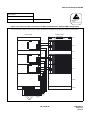
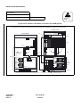
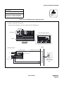
INSTALLATION DESIGN
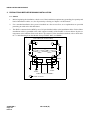
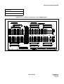
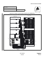
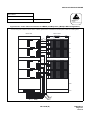
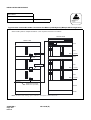
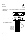
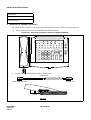
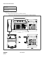
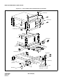
Figure 2-5 Face Layout (Single IMG Configuration)
TOPU
Single IMG
PWR
ON
MJ
MN
SYSTEM
MJ
MN
ALM
SUP/IP
00 01 02 03 04 05 06 07 08 09 10 11 12 13 14 15 16 17 18 19 20 21 22 23
PH-PC36 (MUX1)
PH-PC36 (MUX0)
PA-PW54-B (PWR1)
PA-PW55-B (PWR0)
PIM 3
00 01 02 03 04 05 06 07 08 09 10 11 12 13 14 15 16 17 18 19 20 21 22 23
PH-PC36 (MUX1)
PH-PC36 (MUX0)
PA-PW54-B (PWR1)
PA-PW55-B (PWR0)
PIM 2
FANU
00 01 02 03 04 05 06 07 08 09 10 11 12 13 14 15 16 17 18 19 20 21 22 23
PH-PC36 (MUX1)
PH-PC36 (MUX0)
PA-PW54-B (PWR1)
PA-PW55-B (PWR0)
PIM 1
00 01 02 03 04 05 06 07 08 09 10 11 12 13 14 15 16 17 18 19 20 21 22 23
PH-SW10 (TSW1)
PH-SW10 (TSW0)
PA-PW54-B (PWR1)
PA-PW55-B (PWR0)
PIM 0
BSCM
LOAD
CPUOPEPMOPE WDT
IMG
1
SYSTEM SELECT 0
01
03 04 05 06 07 08
2
3
STATUS
CPR 1
SYSTEM SELECT 1
SENSEMBR
SYSTEM SELECT 2
POWER
EMA (PX-PC00-A)
IOC (PX-IO00)
Note 1
MISC
MISC
MISC
PWR #1 (PX-PW01)
PWR #0 (PX-PW01)
LPM (MGC)
SLOT NO.
LOAD
1
2
3
4
5
6
0
1
2
3
4
5
6
IMG
2
3
STATUS
SYSTEM SELECT 1
SENSEMBR
CPR 0
SYSTEM SELECT 2
POWER
CPURST
Note 1: IOC card in slot 06 is optional.
Note 2: LANI cards in slots 0, 3 of CPR are optional.
ND-71548 (E)
07/31/02
0
CPUOPEPMOPE WDT
1
SYSTEM SELECT 0
BASEU
CHAPTER 2
Page 18
Issue 2
Note 2
CPURST
SLOT NO.
Note 2
INSTALLATION DESIGN
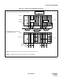
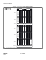
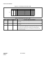
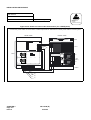
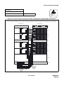
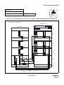
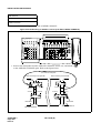
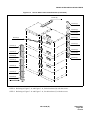
Figure 2-6 Face Layout of Multiple IMG System (IMG0)
IMG 0
Multiple IMG
TOPU
PWR
ON
MJ
MN
SYSTEM
MJ
MN
ALM
SUP/IP
00 01 02 03 04 05 06 07 08 09 10 11 12 13 14 15 16 17 18 19 20 21 22 23
PH-PC36 (MUX1)
PH-PC36 (MUX0)
PA-PW54-B (PWR1)
PA-PW55-B (PWR0)
PIM 3
00 01 02 03 04 05 06 07 08 09 10 11 12 13 14 15 16 17 18 19 20 21 22 23
PH-PC36 (MUX1)
PH-PC36 (MUX0)
PA-PW54-B (PWR1)
PA-PW55-B (PWR0)
PIM 2
FANU
00 01 02 03 04 05 06 07 08 09 10 11 12 13 14 15 16 17 18 19 20 21 22 23
PH-PC36 (MUX1)
PH-PC36 (MUX0)
PA-PW54-B (PWR1)
PA-PW55-B (PWR0)
PIM 1
00 01 02 03 04 05 06 07 08 09 10 11 12 13 14 15 16 17 18 19 20 21 22 23
PH-PC36 (MUX1)
PH-PC36 (MUX0)
PA-PW54-B (PWR1)
PA-PW55-B (PWR0)
PIM 0
BSCM
LOAD
CPUOPE PMOPE WDT
IMG
SYSTEM SELECT 0
01
03 04 05 06 07 08
1
2
3
STATUS
CPR 1
SYSTEM SELECT 1
SENSE MBR
SYSTEM SELECT 2
Note 2
POWER
EMA (PX-PC00-A)
IOC (PX-IO00)
MISC/IOC
Note 1
MISC
MISC
PWR #1 (PX-PW01)
PWR #0 (PX-PW01)
LPM (MGC)
CPURST
LOAD
SLOT NO.
0
1
2
3
4
5
6
SLOT NO.
0
1
2
3
4
5
6
CPUOPE PMOPE WDT
IMG
SYSTEM SELECT 0
1
2
3
STATUS
SYSTEM SELECT 1
SENSE MBR
CPR 0
SYSTEM SELECT 2
POWER
Note 2
CPURST
BASEU
Note 1: IOC card in slot 06 is optional.
Note 2: LANI cards in slots 0, 3 of CPR are optional.
ND-71548 (E)
07/31/02
CHAPTER 2
Page 19
Issue 2
INSTALLATION DESIGN
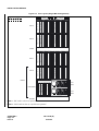
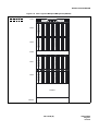
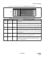
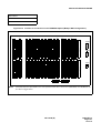
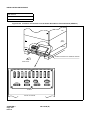
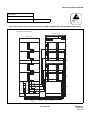
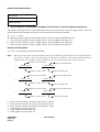
Figure 2-7 Face Layout of Multiple IMG System (IMG1)
IMG 1
Multiple IMG
TOPU
PWR
ON
MJ
MN
SYSTEM
MJ
MN
ALM
SUP/IP
00 01 02 03 04 05 06 07 08 09 10 11 12 13 14 15 16 17 18 19 20 21 22 23
PH-PC36 (MUX1)
PH-PC36 (MUX0)
PA-PW54-B (PWR1)
PA-PW55-B (PWR0)
PIM 3
00 01 02 03 04 05 06 07 08 09 10 11 12 13 14 15 16 17 18 19 20 21 22 23
PH-PC36 (MUX1)
PH-PC36 (MUX0)
PA-PW54-B (PWR1)
PA-PW55-B (PWR0)
PIM 2
FANU
00 01 02 03 04 05 06 07 08 09 10 11 12 13 14 15 16 17 18 19 20 21 22 23
PH-PC36 (MUX1)
PH-PC36 (MUX0)
PA-PW54-B (PWR1)
PA-PW55-B (PWR0)
PIM 1
00 01 02 03 04 05 06 07 08 09 10 11 12 13 14 15 16 17 18 19 20 21 22 23
PH-PC36 (MUX1)
PH-PC36 (MUX0)
PA-PW54-B (PWR1)
PA-PW55-B (PWR0)
PIM 0
00 01 02 03 04 05 06 07 08 09 10 11 12 13 14 15 16 17 18 19 20 21 22 23
Note:
No circuit card is mounted in Slot 02 of TSWM.
CHAPTER 2
Page 20
Issue 2
ND-71548 (E)
PH-CK16/17 (PLO1)
BASEU
PH-CK16/17 (PLO0)
PH-SW12 (TSW13)
PH-SW12 (TSW12)
PH-SW12 (TSW11)
PH-SW12 (TSW10)
PH-SW12 (TSW03)
PH-SW12 (TSW02)
PH-SW12 (TSW01)
PH-SW12 (TSW00)
PH-GT09 (GT1)
PH-GT09 (GT0)
PH-PC20 (DLKC)
PH-PC20 (DLKC)
MISC
MISC
MISC
MISC
MISC
PH-PW14 (PWRSW1)
PH-PW14 (PWRSW0)
TSWM
INSTALLATION DESIGN
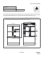
Figure 2-8 Face Layout of Multiple IMG System (IMG2/3)
IMG 2/3
Multiple IMG
TOPU
PWR
ON
MJ
MN
SYSTEM
MJ
MN
ALM
SUP/IP
00 01 02 03 04 05 06 07 08 09 10 11 12 13 14 15 16 17 18 19 20 21 22 23
PH-PC36 (MUX1)
PH-PC36 (MUX0)
PA-PW54-B (PWR1)
PA-PW55-B (PWR0)
PIM 3
00 01 02 03 04 05 06 07 08 09 10 11 12 13 14 15 16 17 18 19 20 21 22 23
PH-PC36 (MUX1)
PH-PC36 (MUX0)
PA-PW54-B (PWR1)
PA-PW55-B (PWR0)
PIM 2
FANU
00 01 02 03 04 05 06 07 08 09 10 11 12 13 14 15 16 17 18 19 20 21 22 23
PH-PC36 (MUX1)
PH-PC36 (MUX0)
PA-PW54-B (PWR1)
PA-PW55-B (PWR0)
PIM 1
00 01 02 03 04 05 06 07 08 09 10 11 12 13 14 15 16 17 18 19 20 21 22 23
PH-PC36 (MUX1)
PH-PC36 (MUX0)
PA-PW54-B (PWR1)
PA-PW55-B (PWR0)
PIM 0
DUMMY
BASEU
ND-71548 (E)
CHAPTER 2
Page 21
Issue 2
INSTALLATION DESIGN
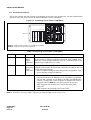
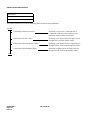
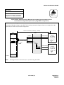
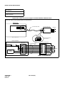
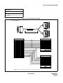
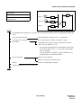
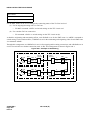
9.2 Circuit Card Locations
This section explains the main function of controlling circuit cards on a module basis. For more detailed information on each card, please refer to the NEAX2400 IPX Circuit Card Manual.
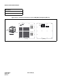
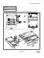
Figure 2-9 Controlling Circuit Cards in LPM (MGC)
CPR#1
LOAD
CPUOPE PMOPE
WDT
IMG
1
SYSTEM SELECT 0
2
3
STATUS
SYSTEM SELECT 1
01
03
SYSTEM SELECT 2
04 05 06 07 08
CPURST
EMA (PX-PC00-A)
IOC (PX-IO00)
MISC/IOC Note 2
MISC
MISC
PWR #1 (PX-PW01)
PWR #0 (PX-PW01)
LPM (MGC)
LOAD
SENSEMBR
POWER
CPUOPE PMOPE
Slot No. 0
1
2
3
4
5
Note
1
6
Slot No. 0
1
2
3
4
5
Note
1
6
WDT
IMG
1
SYSTEM SELECT 0
2
3
STATUS
SYSTEM SELECT 1
SYSTEM SELECT 2
CPURST
SENSEMBR
POWER
CPR#0
Note 1: LANI cards in slots 0, 3 of CPR are optional.
Note 2: IOC card in slot 06 is optional.
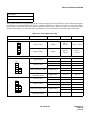
Table 2-4 Controlling Circuit Cards in LPM (MGC)
Slot No.
Circuit Card
Symbol
Functions, Mounting Conditions
06, 07
PX-IO00
IOC
(Input/
Output
Controller)
This circuit card supplies the system with a serial interface (RS-232C),
which connects to external equipment such as the MAT, SMDR, and
MCI. One card is equipped with four I/O ports. A maximum port of the
system is up to eight ports (two cards).
08
PX-PC00-A
EMA
(Emergency
Alarm
Controller)
This card detects the system event which might occur in the system, and
notify the information to the maintenance personnel. In addition, this card
has the following functions:
• Music-On-Hold sending function (Single IMG configuration only)
• Active/stand-by changeover function
CPR (Central Processor Rack)
CPR consists of the following components.
• CPU Board: Includes the Main Processor Unit (MPU), flash ROM,
and 256 MB - Random Access Memory (RAM). (256 MB-RAM is
used for a system using FUSION features.) In addition, the board is
equipped with GT (Note 3) card, and LANI (PZ-PC19) card.
• DSP: Equipped with switches and 7-seg LEDs on the panel.
• Flash card
• PWR: Supplies the operating power to the LPM.
Note 3: PZ-GT25 is for Single IMG, PZ-GT26 is for Multiple IMG systems respectivery.
CHAPTER 2
Page 22
Issue 2
ND-71548 (E)
07/31/02
INSTALLATION DESIGN
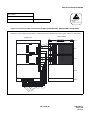
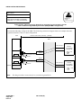
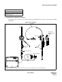
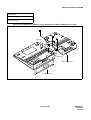
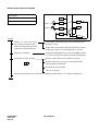
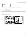
Figure 2-10 Controlling Circuit Cards in PIM 0 (Single IMG Configuration Only)
00 01 02 03 04 05 06 07 08 09 10 11 12 13 14 15 16 17 18 19 20 21 22 23
PH-SW10 (TSW0)
PH-SW10 (TSW1)
PA-PW54-B (PWR1)
PA-PW55-B (PWR0)
PIM0
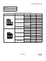
Table 2-5 Controlling Circuit Cards in PIM 0 (Single IMG Configuration Only)
Slot No.
Circuit Card
Symbol
Functions, Mounting Conditions
01
PA-PW55-B
PWR
This circuit card supplies operating power to circuit cards accommodated
in the PIM.
03
PA-PW54-B
DPWR
This circuit card supplies operating power to circuit cards accommodated
in the PIM.
13, 14
PH-SW 10
TSW
This circuit card combines the Time Division Switch (TSW) INT, PLO,
MUX, and CFT. The TSW capacity is 2048 × 2048 time slots, and it
allows non-block switching for the maximum configuration. This card is
mounted within the PIM0 only.
ND-71548 (E)
CHAPTER 2
Page 23
Issue 2
INSTALLATION DESIGN
Figure 2-11 Controlling Circuit Cards in PIM
00 01 02 03 04 05 06 07 08 09 10 11 12 13 14 15 16 17 18 19 20 21 22 23
PH-PC36 (MUX1)
PH-PC36 (MUX0)
PA-PW54-B (PWR1)
PA-PW55-B (PWR0)
PIM
Table 2-6 Controlling Circuit Cards in PIM
Slot No.
Circuit Card
Symbol
Functions, Mounting Conditions
01
PA-PW55-B
PWR
This circuit card supplies operating power to circuit cards accommodated
in the PIM.
03
PA-PW54-B
DPWR
This circuit card supplies operating power to circuit cards accommodated
in the PIM.
13, 14
PH-PC36
MUX
This circuit card is an interface card for mounting line circuits and/or
trunks. Between the CPR and the Port Microprocessor (PM) of the line/
trunk circuit, this card provides an interface for multiplexing/demultiplexing voice PCM (Pulse Code Modulation) information and
digital data information.
CHAPTER 2
Page 24
Issue 2
ND-71548 (E)
INSTALLATION DESIGN
Figure 2-12 Controlling Circuit Cards in TSWM (Multiple IMG Configuration)
00 01 02 03 04 05 06 07 08 09 10 11 12 13 14 15 16 17 18 19 20 21 22 23
PH-CK16/17 (PLO1)
PH-CK16/17 (PLO0)
PH-SW12 (TSW0)
PH-SW12 (TSW0)
PH-SW12 (TSW1)
PH-SW12 (TSW0)
PH-SW12 (TSW0)
PH-SW12 (TSW1)
PH-SW12 (TSW0)
PH-SW12 (TSW0)
PH-GT09 (GT1)
PH-GT09 (GT0)
PH-PC20 (DLKC1)
PH-PC20 (DLKC0)
PH-PW14 (PWRSW1)
PH-PW14 (PWRSW0)
TSWM
Table 2-7 Controlling Circuit Cards in TSWM (Multiple IMG Configuration)
Slot No.
Circuit Card
Symbol
Functions, Mounting Conditions
00, 01
PH-PW14
PWRSW
This circuit card supplies operating power to circuit cards accommodated
in the TSWM.
08, 09
PH-PC20
DLKC
This circuit card provides the Attendant Consoles (ATTs) with
information such as ATT call termination/answer/release (abandoned
call) via the Data Link which is established in the TSW card. In addition,
station idle/busy information is sent to the ATTs via the same Data Link.
10, 11
PH-GT09
GT
This circuit card permits the CPU to directly control the TSW, PLO,
DLKC, and MISC circuit cards via TSW I/O Bus and MISC I/O Bus.
12-19
PH-SW12
TSW
This circuit card supplies the Time Division Switch (TSW) and INT
function for the system. The TSW capacity is 8192 × 2048 TS (time slots)
for an IMG, and 4 cards achieves 8192 × 8192 TS switching for Multiple
IMG configuration.
21, 23
PH-CK16
PLO
This circuit card, used with a digital interface circuit card, sets up network
synchronization. With this circuit card, the IPX Multiple IMG system can
be a clock subordinate office of the digital network.
21, 23
PH-CK17
PLO
This circuit card, used with a digital interface circuit card, sets up network
synchronization. Since this circuit card provides high precision base
clock oscillator, the IPX Multiple IMG system can be a clock source
office of the digital network.
ND-71548 (E)
CHAPTER 2
Page 25
Issue 2
INSTALLATION DESIGN
9.3 Preparation of Trunking Diagram
Prepare the trunking diagram for the customer’s specification. Since there are different types of switching offices (such as a single office, network offices, etc.) are involved, the trunking diagram must be prepared for each
of the customer’s specification.
9.4 Preparation of Module Group Face Layout And Port Accommodation Diagram
To mount circuit cards in the PBX, the company, which is supposed to install the IPX, should prepare the face
layout of module group and port accommodation diagram.
9.5 Preparation of Circuit Card Switch Setting Sheets
Prepare the switch setting sheets for the circuit cards to be mounted in the PBX. Some of the circuit cards might
not be operated properly with the initial settings due to some reason such as not meet the customer’s specification. Refer to the Circuit Card Manual describing the switch settings on Switch Setting Sheets and make sure
the switch setting entries.
Keep in mind that the card needs settings suitable for the surroundings.
10. INSTALLATION CABLES
The following installation cables are required for the PBX:
•
DC Power Cable:
For connections between the Rectifier and battery and between the Rectifier and the PBX
•
AC Power Cable:
For supplying AC source power to the Rectifier
•
Ground Cable:
Communication, Security and Line Protector grounding
•
25P Shielded Cable with CHAMP
•
(Amphenol) connector at one end:
•
25P Shielded Cable with CHAMP
•
(Amphenol) connector at both ends:
For connections between the MAT and the PBX, and between peripheral equipment and the PBX
•
House Cable:
For connections between terminals (telephone sets, etc.) and
the MDF
•
Cables for C.O. lines and Tie Lines
•
Others:
CHAPTER 2
Page 26
Issue 2
For connections between the MDF and the PBX
For connections between Alarm Indicators and the MDF
ND-71548 (E)
INSTALLATION DESIGN
10.1 AC Input, DC Power, And Ground Cables
1.
For AC input cable, VCT (Polyvinyl Chloride Cabtyre Cable) is to be used. However, if shielding is necessary, as is the case when the AC input cable is to be installed in parallel with a low-voltage power cable,
etc., be sure to use VCT-S (Shielded Polyvinyl Chloride Cabtyre Cable).
2.
For the power receiving terminals of the PBX, -48 V and G terminals are provided in dual (A side and B
side). For two PIMs or less, the DC main power cable connects only to A side terminals. For three PIMs
or more, the cable is branched out. A side supplies power to LPM, PIM0 and PIM1, and B side to PIM2
and PIM3.
3.
For the main ground cable, an IV or CV cable of more than 14 mm2 (6 AWG) is to be used. (See Figures
2-13 through 2-15).
As the security ground cable for the MAT and externally installed equipment, IV cable of 2 mm2 (14 AWG)
is to be used. For the ground cable for the line protector of the MDF, an IV cable of 14 mm2 (6 AWG) is to
be used.
Figure 2-13 DC Main Power Cable and Main Ground Cable (1- or 2-PIM System) (Single IMG Configuration)
BATTERY
CABLES
PBX
(For 1/2 PIM Configuration)
RECTIFIER
BATTERY
IV (BL)
IV (R)
POWER AND
GROUND CABLES
CV or IV
-48V
G
-48V
A B
AC POWER
DISTRIBUTION
BOARD
G
A B FE
-48V
G
E
FE
MAT
AC SERVICE
OUTLET
VCT CABLE
MDF
Earth Bar
G
IV (G)
(ex. 6 AWG)
CABLE
DC Main Power Cable
Main Ground Cable
Note:
GROUND
TERMINAL
SPECIFICATION
Calculate the sectional area of cable referring to Figure 2-16.
More than 14 mm2 (6AWG)
If the cover of CV Cable to be used is black, use the following clamp cover terminals so they can be
easily identified.
-48V: Black cover
G: Red cover
E: Green cover
ND-71548 (E)
CHAPTER 2
Page 27
Issue 2
INSTALLATION DESIGN
Figure 2-14 DC Main Power Cable and Main Ground Cable (3- or 4-PIM System) (Single IMG Configuration)
BATTERY
CABLES
PBX
(For 3/4 PIM Configuration)
RECTIFIER
BATTERY
IV (BL)
IV (R)
-48V
G
POWER AND
GROUND CABLES
CV or IV
-48V
A B
G
A B FE
IV (R)
IV (BL)
AC POWER
DISTRIBUTION
BOARD
-48V
G
E
FE
MAT
AC SERVICE
OUTLET
IV (G) (ex. 14 AWG)
VCT CABLE
MDF
Earth Bar
G
IV (G)
(ex. 6 AWG)
CABLE
DC Main Power Cable Main Cable
Branch Cable
Main Ground Cable
GROUND
TERMINAL
SPECIFICATION
Calculate the sectional area of cable referring to
Figure 2-16.
IV cable: more than 14 mm2 (6 AWG)
More than 14 mm2 (6 AWG)
Note 1: If the cover of CV Cable to be used is black, use the following clamp cover terminals so they can be
easily identified.
-48V: Black cover
G: Red cover
E: Green cover
Note 2: Extension jointing is usually performed with a T-type terminal for wires of the same size. Refer to Tables
2-8 through 2-10.
Note 3: It is recommended that each -48V lead of A and B be connected to a separate circuit breaker at the rec-
tifier.
CHAPTER 2
Page 28
Issue 2
ND-71548 (E)
INSTALLATION DESIGN
Figure 2-15 DC Main Power Cable and Main Ground Cable (Multiple IMG Configuration)
IMG 0
NFB
DFB
CV or IV
CV or IV
CV or IV
CV or IV
IMG 1
IMG 2
IMG 3
-48V GND
-48V GND
-48V GND
-48V GND
A B A B FE A B A B FE A B A B FE A B A B FE
IV (BL)
IV (R)
BATTERY
BATTERY
CABLES
IV (BL)
IV (R)
AC POWER
DISTRIBUTION
BOARD
VCT
CABLES
IV (BL)
IV (R)
RECTIFIER
-48V
G
-48V
POWER AND GROUND CABLES
G
E
FE
MAT
AC SERVICE
OUTLET
IV (G)
(ex. 14AWG)
iv(g)
MDF
Earth Bar
G
IV (G)
(ex. 6AWG)
GROUND
TERMINAL
Note 1: Do not make a multiple connection across “A” terminal and “B” terminal of -48V. Likewise, do not
make a multiple connection across “A” terminal and “B” terminal of GND.
Note 2: It is recommended that each -48V lead from the PBX be connected to a separate circuit breaker at the
rectifier.
Note 3: When the lightning occurs, it might cause the difference of voltages between IMGs, and damage these
electric circuits. To keep from the differences of voltages in case, use one main power to connect the
IMGs.
The cables between connecting each of the terminal boards must be as short as possible.
ND-71548 (E)
CHAPTER 2
Page 29
Issue 2
INSTALLATION DESIGN
Table 2-8 Clamp Terminal Shape and Purpose
TYPE
SHAPE
PURPOSE
End terminal
A
Branch or extend power cable
T
CHAPTER 2
Page 30
Issue 2
ND-71548 (E)
REMARKS
INSTALLATION DESIGN
Table 2-9 Selection of T-type Clamp Terminal
14 AWG/
12 AWG/
10 AWG/
8 AWG/
6 AWG/
2 mm2
3.5 mm2
5.5 mm2
8 mm2
14 mm2
CURRENT
10 AWG
*T-20
*T-20
*T-20
-
-
51A
8 AWG
*T-20
*T-20
*T-20
T-20
-
63 A
6 AWG
T-20
T-20
T-20
T-26
T-44
90 A
3 AWG
T-26
T-26
T-44
T-44
T-44
115A
2 AWG
*T-44
T-44
T-44
T-44
T-44
139A
1 AWG
*T-44
*T-44
T-44
T-66
T-60
162A
1ø
*T-60
T-60
T-60
T-60
T-76
190A
2ø
*T-76
T-76
T-76
T-76
T-76
217A
3ø
*T-98
*T-98
*T-98
T-98
T-98
257A
4ø
*T-122
*T-122
*T-122
*T-122
T-122
298A
250 mcm
*T-154
*T-154
*T-154
T-154
T-154
344A
300 mcm
*T-154
*T-190
*T-190
*T-190
T-190
395A
400 mcm
*T-240
*T-240
*T-240
*T-240
T-240
439A
BRANCH
MAIN
Note:
REMARKS
Selection of T-Type Clamp Terminal
The asterisk (*) in Table 2-9 indicates that an auxiliary conductor is necessary when using a main power
wire and a branch power wire of a thinner diameter, and the clamp terminal of the type indicated in the
selected columns.
ND-71548 (E)
CHAPTER 2
Page 31
Issue 2
INSTALLATION DESIGN
Table 2-10 Clamping Tool
APPLICABLE CROSS
*TOOL TYPE
SECTION OF WIRE (mm2)
No. 1
0.25 ~ 6.64
No. 2
6.64 ~ 10.25
No. 9
6.64 ~ 42.42
Convex die 2 pieces
No. 10
6.64 ~ 117.02
Convex die 4
Convex die 8
No. 11
6.64 ~ 117.02
Convex die 4
Convex die 8
No. 12
117.02 ~ 325
Convex die 4
Convex die 4
ACCESSORIES
REMARKS
Manual type for A and C type terminal
No. 13
Rubber hose
Handling type hydraulic tool for A, C,
D, type terminal
Pedal type hydraulic tool for all
terminal types
No. 11 and No. 12 tools are used with
No. 13.
No. 15
14 ~ 122
Convex die 7 pairs
Handling type hydraulic tool for T
type terminal
No. 16
123 ~ 365
Convex die 5 pairs
Use with No. 13 for T type terminal
Figure 2-16 Calculation Method for Sectional Area
RECTIFIER
BATTERY
I1 M 1
PBX
I2 M 2
S = 0.018x(I1M1+I2M2)
V
where,
S : Sectional area required (mm2)
I1 : Max. current passing between battery and rectifier
M1 : Two-way cable length between battery and rectifier
I2 : Max. current passing between rectifier and PBX
M2 : Two-way cable length between rectifier and PBX
V : Voltage drop
CHAPTER 2
Page 32
Issue 2
ND-71548 (E)
INSTALLATION DESIGN
10.2 Cables Between The PBX And MDF
Regarding lines, trunks, and NCU (PFT), 25P shielded the PBX and the MDF are connected by using cables
with a CHAMP (Amphenol) connector at one end.
Table 2-11 shows the procedure for calculating the required number of cables. Figure 2-17 also shows an outline
of cable connections from the Module Group to the outside.
Table 2-11 Calculation of Number of Cables
CABLE NAME
CALCULATION
LT Cable
Number of PIMs × 12
NCU Cable
Number of PFT Circuit Cards × 2
IPX EXALM CA-A
One cable
ODT Cable
Number of TLT circuit cards × 1
SUB TOTAL
TOTAL
ND-71548 (E)
CHAPTER 2
Page 33
Issue 2
INSTALLATION DESIGN
Figure 2-17 Outline of Cables from Module Group to the Outside
CONNECTOR
DESIGNATION
CONNECTOR
DESIGNATIION LEAD
DESIGNATION
LEAD
DESIGNATION
MDF
PBX
MDF
LT-X Axx
LT-X Bxx
LT-X Axx
COT
LC
LT-X Bxx
LT-X Axx
INST.
CABLE
TO C.O.
OR
DISTANT
PABX
LT-X Bxx
TLT
LT-X Bxx
LT-X Mxx
SWITCHING
FACILITIES
INST.
CABLE
LT-X Axx
LT-X Bxx
COT
LC
NCU-X-AOx
NCU-X-BOx
NCU-X-Alx
LT-X Axx
LT-X Bxx
NCU-X ROx
NCU-X TOx
NCU-X Rlx
NCU-X Tlx
NCU-X-Blx
PFT
ALM MJ
ALM MN
TO ALARM
INDICATOR
ALM E
INST.
CABLE
Note 1: Legend
IPX EXALM CA-A
: Male CONNECTOR
: Female CONNECTOR.
Note 2: “
” or “
” in the above drawing indicates the CONNECTOR ended.
Cable to be connected between module connector and MDF.
CHAPTER 2
Page 34
Issue 2
ND-71548 (E)
INST.
CABLE
INSTALLATION PROCEDURE
CHAPTER 3
INSTALLATION PROCEDURE
1. GENERAL
This chapter explains the procedures for installing the PBX, the Maintenance Administration Terminal (MAT),
Desk Consoles, and various types of terminal equipment (single line telephones, Dterms, Data Modules, etc.).
The procedures in this chapter are shown in Figure 3-1.
Before installing it, thoroughly read Section 2., “PRECAUTIONS BEFORE BEGINNING INSTALLATION”
and observe the precautions while performing the installation.
Figure 3-1 Scope of Installation Procedure
Installation of Peripheral
Equipment (NAP-200-015)
Installation Preparation-Basic Procedures
(NAP-200-001, 002, 003)
C.O./Tie Line
Single-line TEL
Assembly and Installation of the Module
Group (NAP-200-004, 005)
Digital Interface
Cable Termination
(NAP-200-014)
Paging/Announcement
ALM IND./TAS IND./External
Key Box
CHAMP Connector
Cable Running
(NAP-200-013)
Installation of MDF
(NAP-200-007)
Desk Console
Circuit Card
Related
Procedures
(NAP-200-016)
Maintenance
Administration
Terminal
(NAP-200-009)
(NAP-200-017)
SMDR Interface
(NAP-200-018)
Power & Ground Cabling
(NAP-200-008)
Cabling within the Module Group
(NAP-200-010, 012)
Mounting of Covers and
Post-Installation Procedures
Refer to Chapter 7.
Note:
RECT/
BATT
Power Equipment Installation
(NAP-200-006)
Work procedures are explained in detail in each NAP. Refer to the procedures by number (NAP-200XXX).
ND-71548 (E)
07/31/02
CHAPTER 3
Page 35
Issue 2
INSTALLATION PROCEDURE
2. PRECAUTIONS BEFORE BEGINNING INSTALLATION
2.1 Outline
1.
Before beginning the installation, check to see if the installation requirements (grounding, the quantity and
kind of installation cables, etc.) are all present by referring to Chapter 2 of this manual.
2.
For a standard installation, the system is installed on a free-access floor, so no explanations are provided
pertaining to cable racks and cable ducts.
3.
The PBX is connected to the MDF by use of 25-pair shielded cables as the installation cables. Each of these
installation cables is grounded at the cable support assembly of the BASEU as shown below. By this arrangement, noise radiation from each cable is prevented. For the installation method, refer to NAP-200013: “Cable Running from the Module Group to MDF, MAT, and SMDR.”
INST CABLE (25P AC-BUS CABLE)
LTX
LTX
PIM
BASEU
E
To MDF
To MDF
CABLE SUPPORT ASSEMBLY
: CHAMP Connector
CHAPTER 3
Page 36
Issue 2
ND-71548 (E)
INSTALLATION PROCEDURE
4.
Note:
As the cable to be run between the PBX and the Rectifier, use a CV cable (600 V Crosslinked Polyethylene
Insulated PVC Sheathed Cable) as the circumstance permits. Compared with an ordinary IV cable (600 V
PVC Insulated Cable), the CV cable is stronger because of its thicker cover. Thus, it is suitable to run along
the free-access floor where it is difficult to protect the cable from damage.
Also, for easy identification of different cables, use cables of different colors as follows:
• –48 V:
Blue (White)
• GND:
Red (Black)
• E:
Green
The color shown in a bracket is applicable to the UL Specification.
ND-71548 (E)
CHAPTER 3
Page 37
Issue 2
INSTALLATION PROCEDURE
3. INSTALLATION PROCEDURE
The flowchart in Figure 3-2 shows the installation procedure. Each step is assigned a NAP number. NAPs NAP200-001 through NAP-200-018 follow Figure 3-2. These NAPs should be followed sequentially when performing the installation. Individual steps, such as installation of SMDR, can be performed independently by referring
to the corresponding NAP.
Figure 3-2 Installation Procedure
START
Installation Preparation
Marking, Leveling, and Drilling
Unpacking and Inspection
MDF Installation
(NAP-200-007)
Cable Running
Power Equipment Installation
(NAP-200-001)
(NAP-200-002)
(NAP-200-003)
Base Unit Installation
(NAP-200-006)
(NAP-200-004)
Mounting of Units and Modules
(NAP-200-013)
(PBX->MDF/ATTCON/MAT/SMDR)
Cable Termination
(NAP-200-014)
Cable Termination and Cross
(NAP-200-015)
Connection
(MDF->C.O. Lines/Tie Lines/
Peripheral Equipment)
(NAP-200-005)
Desk Console Setting
(NAP-200-016)
MAT Setting
Power and Ground Cables
Connection (NAP-200-008)
Circuit Cards Setting
(NAP-200-009)
(NAP-200-017)
Cable Connections
Connection of SMDR
(NAP-200-018)
Internal
Cable Connections
(NAP-200-010)
Inter-Frame Cable Connections
(NAP-200-011)
Front Cable Connections between
Circuit Cards (NAP-200-012)
Cleaning and Visual Check
END
CHAPTER 3
Page 38
Issue 2
ND-71548 (E)
INSTALLATION PROCEDURE
NAP-200-001
Sheet 1/2
Installation Preparation
This NAP explains the following work items:
•
Confirmation of Equipment Locations
•
Confirmation of Floor Layout
•
Confirmation of Power and Ground Supply
•
Check of Quantity of Equipment Packages
Note 1: Confirmation procedures are discussed in Chapter 2 of this manual.
Note 2: Be sure to correct any abnormal conditions encountered during installation preparation (missing hard-
ware, floor not level, etc.) before proceeding to the next step.
START
Confirmation of Equipment
Locations
Environmental
Floor Space
Confirmation of temperature and
humidity.
Floor Load
Equipment Room
Floor surface
Wall
Ceiling
Lighting facilities
According to the floor layout,
confirm that the equipment
locations are appropriate.
A
B
Improper Locations:
• An open aisle or place where sprinklers are provided.
• A place where there is a water pipeline.
• A place where there is a pipeline generating heat and an
exhaust for such heat.
• A location near an exhaust port for corrosive fumes or gas
generated from a facility machine.
• A location near a copying machine or apparatus which dissipates heat.
• A location where the switch will be exposed to direct sunlight.
• A location near a kitchen facility, etc., from which vapor is
generated.
• A high EMI environment; for example, a location near an
elevator motor or X-ray equipment.
ND-71548 (E)
CHAPTER 3
Page 39
Issue 2
INSTALLATION PROCEDURE
NAP-200-001
Sheet 2/2
Installation Preparation
A
B
Proper Locations:
• A dry and clean place.
• A place that is well ventilated.
• A sufficiently illuminated room. (200 lux at floor level).
• A location around which there are no obstructing objects,
thus allowing easy maintenance.
• A place where C.O. lines can be brought in, or local
cables can be brought up to the MDF easily.
• A place where communication and security ground can
be obtained as required
Confirmation of Power and
Ground Supply
Confirm AC voltage and current capacity.
Confirm that a Circuit Breaker (NFB) is provided
exclusively for the system.
Confirm that ground terminals are provided separately from
those of the power supply system.
Confirm that one main power is provided to connect the
IMG(s).
Check the Quantity of
Packages
END
CHAPTER 3
Page 40
Issue 2
Check the quantity of packages to see if there is a
discrepancy with the Packing List.
If any equipment is missing, report it to the supplier
immediately.
ND-71548 (E)
INSTALLATION PROCEDURE
NAP-200-002
Sheet 1/8
Marketing, Leveling, and Drilling
This NAP explains the procedures for marking, drilling and other necessary work when the PBX is to be installed
on a free-access floor by either one of the following three methods.
•
Securing the PBX directly onto the floor
•
Securing the PBX with the special stand
•
Securing the PBX with the floor elevation
This NAP also explains the procedures for marking, leveling and drilling for MDF, Power Equipment, and Peripheral Equipment (See Section 4.)
Note:
Kinds of Anchor Bolts
Various types of anchor bolts are available; the type of bolt to be used depends on the application. Sleeve
expansion-type anchor bolts are generally preferred for the PBX installation. Table 002-1 shows anchor
bolt specification.
Table 002-1 Specification of Anchor Bolts-Sleeve Expansion Type
SCREW
M10
SLEEVE
Ø17.3
BOLT
LENGTH
SLEEVE
LENGTH
mm
inch
mm
inch
50
2
38
1.5
70
2.8
58
80
3.1
68
DRILL
DIA.
DRILLING
DEPTH
MAX. THICKNESS
OF ITEM TO BE
FIXED
APPLICATION
mm
inch
50
2
2.3
70
2.8
Concrete + Mortar
(20 mm/0.8 in
thick)
2.7
80
3.1
Concrete + Mortar
(30 mm/1.2 in
thick)
Ø17.5
15 mm/0.6 in
For concrete
COMPONENTS
Bolts,
Washers,
Nuts
* Pull out Strength = 1,900 Kg (4185 lb)
(Concrete Strength = more than 20, 580, 000 Pa (2984.871 PSI))
ND-71548 (E)
CHAPTER 3
Page 41
Issue 2
INSTALLATION PROCEDURE
NAP-200-002
Sheet 2/8
Marking, Leveling, and Drilling
1. WHEN SECURING THE PBX DIRECTLY ONTO THE FLOOR
START
Marking
Referring to Figure 002-1, mark the holes for the
anchor bolts of the base unit.
Drilling
Drill holes at the locations marked for base unit.
Cutting of Free-Access Floor
Referring to Figure 002-2, cut the free-access floor at
the marked cable locations by using a jigsaw.
Leveling
Measure the level of floor surface of the free-access
floor.
When it is not level, adjust the support of the freeaccess floor until it is level.
END
CHAPTER 3
Page 42
Issue 2
ND-71548 (E)
INSTALLATION PROCEDURE
NAP-200-002
Sheet 3/8
Marking, Leveling, and Drilling
Figure 002-1 Locations of Base Unit Securing Holes
Single IMG Configuration
55(2.17")
550
(1'9.65")
410(1'4.14")
85(3.35")
40
(1.57")
520
(1'8.47")
600
(1'11.62")
40(1.57")
Unit: mm(inch)
Multiple IMG Configuration
IMG0
IMG1
520
(1'8.47")
600
(1'11.62")
520
(1'8.47")
600
(1'11.62")
IMG2
IMG3
55(2.17")
550
(1'9.65") 410(1'4.14")
85(3.35")
40
(1.57")
120
(4.72")
120
(4.72")
520
(1'8.47")
600
(1'11.62")
120
(4.72")
520
(1'8.47")
600
(1'11.62")
40(1.57")
Unit: mm(inch)
ND-71548 (E)
CHAPTER 3
Page 43
Issue 2
INSTALLATION PROCEDURE
NAP-200-002
Sheet 4/8
Marking, Leveling, and Drilling
Figure 002-2 Cable Hole on a Free-Access or Computer Floor
FRONT
PBX
550
(1'9.65")
370
(1'2.57")
115(4.53")
REAR
100(3.94")
115(4.53")
600
(1'11.62")
CABLE HOLE
FREE-ACCESS FLOOR
Unit: mm(inch)
CHAPTER 3
Page 44
Issue 2
ND-71548 (E)
INSTALLATION PROCEDURE
NAP-200-002
Sheet 5/8
Marking, Leveling, and Drilling
2. WHEN SECURING THE PBX WITH THE SPECIAL STAND
START
Marking and Drilling of Special
Stand
Drill the Special Stand for securing the PBX.
(See Figure 002-3.)
Marking, Drilling and Cutting of
Free-Access Floor
Mark, drill, and cut the free-access floor according to
the size of the special stand to be used.
Installing the Special Stand
Secure the special stand onto the floor.
(See Figure 002-4.)
Level Check
Check the level of the special stand. If necessary,
adjust the level by inserting spacers beneath the stand.
END
ND-71548 (E)
CHAPTER 3
Page 45
Issue 2
INSTALLATION PROCEDURE
NAP-200-002
Sheet 6/8
Marking, Leveling, and Drilling
Figure 002-3 Example of Special Stand
HOLE FOR SECURING
BASE UNIT
55
410
(1'4.14")
40
(1.57")
520
(1'8.47")
85
(3.35")
600
(1'11.62")
40
(1.57")
Unit: mm(inch)
Figure 002-4 Special Stand Installation Method
PBX
TOPU
PIM
LPM (MGC)
FRONT
FREE-ACCESS
OR COMPUTER FLOOR
SPECIAL STAND
ANCHOR BOLT
CHAPTER 3
Page 46
Issue 2
ND-71548 (E)
INSTALLATION PROCEDURE
NAP-200-002
Sheet 7/8
Marking, Leveling, and Drilling
3. WHEN SECURING PBX WITH FLOOR ELEVATIONS
START
Installing the Floor Elevation
Secure the Floor Elevation on the concrete floor.
(See Figure 002-5.)
Marking
Mark the locations of the anchor bolt holes for the Base Unit.
(See Figure 002-1.)
Drilling
Drill holes in the locations.
Cutting of Free-Access Floor
Cut the Free-Access Floor with a jigsaw. (See Figure 002-2.)
END
Figure 002-5 Example of Elevation
HOLE FOR SECURING
BASEU
CONCRETE FLOOR
520
(1’8.47”)
410
(1’4.14”)
ANCHOR BOLT
ELEVATION
ND-71548 (E)
CHAPTER 3
Page 47
Issue 2
INSTALLATION PROCEDURE
NAP-200-002
Sheet 8/8
Marking, Leveling, and Drilling
4. MARKING, LEVELING AND DRILLING FOR MDF, POWER EQUIPMENT, AND PERIPHERAL EQUIPMENT
START
Leveling
Measure the level of floor surface and determine the reference
level.
ROOM
HIGHEST LEVEL
WALL
REFERENCE LEVEL
FLOOR
Marking
Mark the holes for securing
equipment
Power Equipment
MDF
Peripheral Equipment
Drilling
Drill holes locations marked for power equipment, MDF, and
peripheral equipment.
Secure the anchor bolts to the floor.
(Embed nuts and sleeves)
Remove the anchor bolts temporarily.
(Remove anchor bolts and washers)
END
CHAPTER 3
Page 48
Issue 2
ND-71548 (E)
INSTALLATION PROCEDURE
NAP-200-003
Sheet 1/2
CAUTION: Equipment may become damaged if
not handled properly during unpacking and inspection.
Unpacking and Inspection
ATTENTION
Contents
Static Sensitive
Handling
Precautions Required
This NAP explains the procedure for unpacking and inspection.
Note 1: If any equipment is missing or damaged, report it to the supplier immediately.
Note 2: Save all packing materials and boxes so that they can be used to return damaged equipment to the supplier.
1. UNPACKING
START
Quantity check
Check the quantity of packages received against the
Packing List.
Check for external damage
Check the packaging for external damage.
Carry-In
Carry the packages containing the Module Group into
the switching equipment room.
Unpacking Note 2
Module Group, Modules, and Units
Covers
Circuit Cards
ATTCON
Cables
END
ND-71548 (E)
CHAPTER 3
Page 49
Issue 2
INSTALLATION PROCEDURE
NAP-200-003
CAUTION: Equipment may become damaged
Sheet 2/2
if not handled properly during
unpacking and inspection.
Unpacking and Inspection
ATTENTION
Contents
Static Sensitive
Handling
Precautions Required
2. INSPECTION
START
Visually Inspect Modules and Units
Overall distortion.
Scratches or dents on the surface.
Distortion of shelves.
Cracks to connectors on the backplane.
Broken or bent pins on the backplane.
Circuit Cards
Provide protection from static
electricity.
Scratches and cracks.
Loose wires and parts.
Damage to card puller tabs.
Desk Console and MAT
Scratches and dents on the body.
Damage to keys and lamps.
END
CHAPTER 3
Page 50
Issue 2
ND-71548 (E)
INSTALLATION PROCEDURE
NAP-200-004
Sheet 1/3
Installation of the Base Unit
This NAP explains the procedure for securing the Base Unit onto the floor directly or using special stand.
1. INSTALLING THE BASE UNIT DIRECTLY ONTO THE FLOOR
START
Securing the Base Unit
Secure the Base Unit onto the floor as per Figure 004-1 and
004-2.
When the floor elevation is in use, secure the Base Unit by
referring to Figures 004-1 and 004-3.
Level Check
Check the level of the Base Unit. If necessary, adjust the level
by inserting spacers beneath the Base Unit.
END
Figure 004-1 Mounting the Base Unit on an Ordinary Floor
BASE
UNIT
BOLT
LOCK WASHER
PLAIN WASHER
ND-71548 (E)
CHAPTER 3
Page 51
Issue 2
INSTALLATION PROCEDURE
NAP-200-004
Sheet 2/3
Installation of the Base Unit
Figure 004-2 Mounting the Base Unit on a Free-Access or Computer Floor
BOLT
BASE UNIT
FREE-ACCESS
FLOOR
FLAT WASHER
COMPRESSED PIPE
FLAT WASHER
CONCRETE
FLOOR
ANCHOR BOLT
Figure 004-3 Mounting the Base Unit on a Free-Access or Computer Floor via Elevation
Example: The floor elevation is higher
than 150 mm (5.9 inches).
FLOOR ELEVATION
BASE UNIT
FREE-ACCESS
FLOOR
CHAPTER 3
Page 52
Issue 2
ND-71548 (E)
INSTALLATION PROCEDURE
NAP-200-004
Sheet 3/3
Installation of the Base Unit
2. INSTALLING THE BASE UNIT USING A SPECIAL STAND
START
Securing the Base Unit
Secure the Base Unit onto the special stand as per Figure 004-4.
Level Check
Check the level of the Base Unit. If necessary, adjust the level by
inserting spacers beneath the Base Unit.
END
Figure 004-4 Setting the BASEU via Special Stand
BASEU
BOLT
LOCK WASHER
PLAIN WASHER
SPECIAL STAND
ND-71548 (E)
CHAPTER 3
Page 53
Issue 2
INSTALLATION PROCEDURE
NAP-200-005
Sheet 1/18
Mounting of Units and Modules
1. MOUNTING OF UNITS AND MODULES
START
Mounting of Modules, FAN
BOX and TOPU
Mount modules, FAN BOX and TOPU for each cabinet, by
referring to the Figure 005-1.
END
Figure 005-1 Procedure for Mounting Units and Modules
(TOPU)
Note
Tighten these screws.
Do the same at the rear
side, too.
(PIM3)
Tighten these screws.
Do the same at the rear
side, too.
(PIM2)
Tighten these screws.
Do the same at the rear
side, too.
(FAN BOX)
Note
Tighten these screws.
Do the same at the rear
side, too.
(PIM1)
Tighten these screws.
Do the same at the rear
side, too.
Note:
FAN Unit (FANU) is
mounted on the TOPU,
or inside the FAN
BOX, and LPM
(MGC). For detailed
procedures, refer to
Section 2 of this NAP.
CHAPTER 3
Page 54
Issue 2
(PIM0)
BSCM
(LPM (MGC))
ND-71548 (E)
INSTALLATION PROCEDURE
NAP-200-005
Sheet 2/18
Mounting of Units and Modules
2. INSTALLATION OF FANU
Location of FANU (PZ-M369 and three electronic FANs) is shown in Figure 005-2. Depending on your system configuration, mount the FANU in the proper position.
Figure 005-2 Locations of FANU
The mounting location of FANU differs depending on the module configuration of each cabinet. When the
cabinet consists of a total of two PIMS or fewer, the FANU is mounted on the TOPU. Otherwise, the FANU
is housed in the dedicated FAN BOX in the center of the cabinet.
NEC
TOPU
TOPU
FAN BOX
NEC
FANU is
located here.
FRONT VIEW
////////////////////////////////////////////////////////////////
<When FANU is mounted on TOPU>
<When FANU is mounted in FAN BOX>
ND-71548 (E)
CHAPTER 3
Page 55
Issue 2
INSTALLATION PROCEDURE
NAP-200-005
Sheet 3/18
Mounting of Units and Modules
3. PROCEDURE FOR FANU ON THE TOPU
When any IMG is configured by two PIMs or less, the FANU is mounted as shown in Figure 005-3. Because the
FANU is already mounted on the TOPU of the cabinet, perform STEP 4 through STEP 7 only, excepting a special
case (STEP 1 through STEP 3 are not required in the normal cases).
STEP 1: Referring to Figure 005-3, mount the three FANs onto the FAN Mounting Plate. Then, fasten every
four screws.
STEP 2: Accommodate the FAN Mounting Plate (tipped with three FANs) onto the TOPU.
Then, tighten the four screws (refer to Figure 005-3).
STEP 3: Mount the PZ-M369 onto the TOPU. Then, fasten the two screws (also refer to Figure 005-3).
Figure 005-3 Mounting of FANU (on TOPU)
ATTENTION
FAN Mounting Plate
Contents
Static Sensitive
Handling
Precautions Required
PZ-M369
TOPU
(TALM)
CHAPTER 3
Page 56
Issue 2
ND-71548 (E)
INSTALLATION PROCEDURE
NAP-200-005
Sheet 4/18
Mounting of Units and Modules
STEP 4: Fix a FAN fuse (5.0A) onto the PZ-M369.
Figure 005-4 Attachment of FAN Fuse (PZ-M369)
ATTENTION
Contents
Static Sensitive
Handling
Precautions Required
TH0
TH1
TH2
FAN
PWR SW
Note
FC0
FC1
FC2
TALM0 TALM1
ON
OFF
Auto
PZ-M369
Fasten a FAN fuse (5.0 A) here.
Note:
Heat run test of the FANU is shown in Chapter 4, ”SYSTEM STARTUP”. Therefore, keep the PWR SW
key to the center position (= OFF), still at this time.
STEP 5: Connect the FAN cables as shown in Figure 005-5 and Figure 005-6.
STEP 6: Lastly, attach the Top Cover onto the TOPU of the cabinet. Then, fasten the four screws (refer to Figure 005-7).
Note:
The procedures, STEP 4 through STEP 6, must be performed at each PBX cabinet adopting 1-PIM or 2PIM configuration.
ND-71548 (E)
CHAPTER 3
Page 57
Issue 2
INSTALLATION PROCEDURE
NAP-200-005
Sheet 5/18
Mounting of Units and Modules
Figure 005-5 Cable Connections for FANU on TOPU
ATTENTION
Contents
Static Sensitive
Handling
Precautions Required
TOPU
PBX
.. .. ..
NEC
NEC
FAN
Note 1
PZ-M369
TH0 TH1 TH2 FAN
FC0 FC1 FC2 TALM0
FANU
THM
Note 2
TALM
TOPU (Top View)
Note 1: For details on the “FAN” connector (PIM backplane), refer to Figure 005-6.
Note 2: For details on the “TALM” connector (TOPU panel), refer to Figure 005-3.
CHAPTER 3
Page 58
Issue 2
ND-71548 (E)
INSTALLATION PROCEDURE
NAP-200-005
Sheet 6/18
Mounting of Units and Modules
Figure 005-6 Connection of “FAN” Connector Cable (TOPU-PIM)
ATTENTION
Contents
Static Sensitive
Handling
Precautions Required
PZ-M369
TH0
TH1
TH2
FAN
FC0
FC1
FC2
TALM0 TALM1
ON
OFF
Auto
TOPU
(FAN)
PIM
(FAN)
PBX
ND-71548 (E)
CHAPTER 3
Page 59
Issue 2
INSTALLATION PROCEDURE
NAP-200-005
Sheet 7/18
Mounting of Units and Modules
Figure 005-7 Attachment of the Top Cover
Mount the Top Cover onto the TOPU.
Then, fasten the four screws by using
the Phillips screwdriver.
Top Cover
TOPU
PIM
NEC
CHAPTER 3
Page 60
Issue 2
ND-71548 (E)
INSTALLATION PROCEDURE
NAP-200-005
Sheet 8/18
Mounting of Units and Modules
4. PROCEDURE FOR FANU IN THE FAN BOX
When any IMG is configured by 3 or 4 PIMs, the FANU must be accommodated within the FAN BOX in the center
of the cabinet. Because the FANU is originally mounted on the TOPU as shown in Figure 005-3, relocate the FANU
into the dedicated FAN BOX as per the STEPs below:
STEP 1: Referring to Figure 005-3, remove the FANU from the TOPU.
• Remove the two screws fastening the PZ-M369. Then, lift away the PZ-M369.
• Remove the four screws fastening the FAN Mounting Plate (tipped with three FANs).
• Then, lift away the FAN Mounting Plate.
Note:
Retain the removed screws.
STEP 2: Fasten the PZ-M369 and FAN Mounting Plate onto the FAN BOX connection bar (refer to Figure
005-8). Use two screws (for PZ-M369) and four screws (for FAN Mounting Plate) retained in STEP
1.
STEP 3: Connect the FAN cables for “FC0,” “FC1” and “FC2” connectors on the PZ-M369. Refer to Figure
005-9.
STEP 4: Insert the FANU, prepared in STEP 1 through STEP 3, into the FAN BOX. Then, secure the FANU
with the two screws (refer to Figure 005-8).
ND-71548 (E)
CHAPTER 3
Page 61
Issue 2
INSTALLATION PROCEDURE
NAP-200-005
Sheet 9/18
Mounting of Units and Modules
Figure 005-8 Relocation of FANU and Insertion into FAN BOX
Screws for FAN Mounting Plate
ATTENTION
Contents
Static Sensitive
Handling
Precautions Required
FAN BOX connection bar
FAN BOX connection bar
Screws for PZ-M369
Note
FAN BOX
Note:
Before inserting the FANU into the FAN BOX, connect the FAN cables for “FC0,” “FC1,” and “FC2”
connectors on the PZ-M369. Refer to Figure 005-9.
CHAPTER 3
Page 62
Issue 2
ND-71548 (E)
INSTALLATION PROCEDURE
NAP-200-005
Sheet 10/18
Mounting of Units and Modules
Figure 005-9 FAN Cable Connections for FC0/FC1/FC2 Connectors
Before installing the FANU into the FAN BOX, connect FAN cables as shown below.
ATTENTION
Contents
Static Sensitive
Handling
Precautions Required
FAN0
FAN1
FAN2
FC0 FC1 FC2
PZ-M369
ND-71548 (E)
CHAPTER 3
Page 63
Issue 2
INSTALLATION PROCEDURE
NAP-200-005
Sheet 11/18
Mounting of Units and Modules
STEP 5: Fix a FAN fuse (5.0A) onto the PZ-M369 by referring to Figure 005-4.
STEP 6: Connect the remaining FAN cables as per Figure 005-10 and Figure 005-11.
STEP 7: Lastly, attach the Top Cover onto the TOPU of the cabinet. Then, fasten the four screws (refer to Figure 005-7).
Note:
The procedures, STEP 1 through STEP 7, must be performed at each PBX cabinet adopting 3-PIM or 4PIM configurations.
CHAPTER 3
Page 64
Issue 2
ND-71548 (E)
INSTALLATION PROCEDURE
NAP-200-005
Sheet 12/18
Mounting of Units and Modules
Figure 005-10 Cable Connections for FANU in FAN BOX
(
)
T T
H H
2 2
(
T T
H H
1 1
ATTENTION
)
Contents
Static Sensitive
Handling
Precautions Required
(
)
T T
H H
0 0
TOPU
..
NEC
THM
Note 2
TALM
TOPU (Top View)
T
A
L
M
0
T
A
L
M
PBX
NEC
TH0TH1TH2FAN
TALM0
NEAX 2400 IMS
PZ-M369
Note 1
PZ-M369 (Front View)
FAN BOX
Note 1: For details on the “FAN” connector (PIM backplane), refer to Figure 005-11.
Note 2: For details on the “TALM” connector (TOPU), refer to Figure 005-3.
ND-71548 (E)
CHAPTER 3
Page 65
Issue 2
INSTALLATION PROCEDURE
NAP-200-005
Sheet 13/18
Mounting of Units and Modules
Figure 005-11 Connection of “FAN” Connector Cable (FAN BOX-PIM)
PBX
ATTENTION
Contents
Static Sensitive
Handling
Precautions Required
FAN power cable
(FAN)
FAN BOX
FAN BOX
FAN power cable
(FAN)
TH0
TH1
TH2
FAN
FC0
FC1
FC2
TALM0 TALM1
ON
OFF
Auto
PZ-M369
CHAPTER 3
Page 66
Issue 2
ND-71548 (E)
INSTALLATION PROCEDURE
NAP-200-005
Sheet 14/18
Mounting of Units and Modules
5. ATTACHING THE ADDITIONAL NOISE FILTER UNIT (NFILU) TO THE BASEU
The following flowchart shows the procedure for attaching the Additional Noise Filter Unit (NFILU) to the BASEU
of the PBX. This work should be performed when the module stack contains 3 or 4 PIMs.
STAR
T
Referring to Figure 005-12 and Figure 005-13, insert the NFILU to BASEU and attach the NFILU with
two screws.
Referring to Figure 005-14, connect the cables equipped with NFILU to the terminals on the BASEU.
END
ND-71548 (E)
CHAPTER 3
Page 67
Issue 2
INSTALLATION PROCEDURE
NAP-200-005
Sheet 15/18
Mounting of Units and Modules
Figure 005-12 Insertion of NFILU
SCREW
BASEU
NOISE FILTER UNIT (NFILU)
Figure 005-13 Attaching of NFILU
SCREW
SCREWS
BASEU
CHAPTER 3
Page 68
Issue 2
ND-71548 (E)
INSTALLATION PROCEDURE
NAP-200-005
Sheet 16/18
Mounting of Units and Modules
Figure 005-14 Cabling Diagram of NFILU
BASEU
(GB1)
(-48VB)
(GB0)
(3)
(PZ-M371)
(4)
Already Attached
Noise Filter Unit
(1)
(PZ-M377)
(2)
(G)
(1)
(2)
(-48V)
Additional
Noise Filter
Unit (NFILU)
FRONT
ND-71548 (E)
CHAPTER 3
Page 69
Issue 2
INSTALLATION PROCEDURE
NAP-200-006
Sheet 1/1
Installation of Power Equipment
ATTENTION
This NAP explains the procedures for installing the power equipment.
Note:
Contents
Static Sensitive
Handling
Precautions Required
The Circuit Breaker (NFB) for the Rectifier's DC output must remain OFF.
START
Install the power equipment at the predetermined location using anchor bolts, etc. Install the framework
for the batteries to be used for backup. Secure the framework using anchor bolts, etc.
Check the cabling at the primary and secondary sides of the power equipment, and the cabling to the
batteries
Confirm that the specifications of the customer-installed AC PDB (NFB capacity, voltage, phase, etc.)
conform to the specifications of the Rectifier.
Confirm that the proper communication ground is available.
Connect the input power cable and grounding cable to the rectifier.
Supply electrolyte to each battery as per the specifications of the battery.
Charge the batteries after verifying that the rectifier is operating normally.
END
CHAPTER 3
Page 70
Issue 2
ND-71548 (E)
INSTALLATION PROCEDURE
NAP-200-007
Sheet 1/1
Installation of the MDF
ATTENTION
This NAP explains the procedures for installing the MDF.
Contents
Static Sensitive
Handling
Precautions Required
START
Install the MDF at the predetermined location on the floor or wall. Be sure to check the quantity of
accessory items such as arresters, block terminals, etc.
Install the MDF, taking into consideration the locations of lead-in holes for Local Cable, C.O. lines, Tie
Lines, and Cable Running Routes.
MDF Line Protector Ground must be separated from the Communication Ground connected to the
rectifier.
END
ND-71548 (E)
CHAPTER 3
Page 71
Issue 2
INSTALLATION PROCEDURE
NAP-200-008
Sheet 1/13
ATTENTION
Connection of Power and Ground
Cables from the Power Equipment
Contents
Static Sensitive
Handling
Precautions Required
This NAP explains the following work items.
•
Connection of Power and Ground Cables
•
Connection of DC-DC Converter for Telephone sets equipped with Message Waiting Lamps
•
End Jointing of Power and Ground Cables
•
Branching of Power Cables
1. CONNECTION OF THE POWER AND GROUND CABLES
CAUTION: Grounding circuit continuity is vital for safe operation of telecommunication equipment.
Never operate telecommunication equipment with grounding conductor disconnected.
START
Cable Running
Run the power and ground cables per
Figure 008-1 and Figure 008-3.
Running of power and ground cables to the
Power Receiving Terminals in the BASEU
An example of cable running on a free access or
computer floor is shown in Figure 008-1.
Confirming that the Circuit Breaker (NFB) of the Rectifier is OFF.
Connection of the power and ground cables
Connect the power and ground cables to the
Power Receiving Terminals on the BASEU per
Figure 008-3.
Connect the power and ground cables to the
output terminals of the Rectifier.
Check after cable connections
Using a continuity tester, confirm that the -48 V
power cable is not shorting to the G power cable
or FE ground cable.
END
CHAPTER 3
Page 72
Issue 2
ND-71548 (E)
INSTALLATION PROCEDURE
NAP-200-008
Sheet 2/13
Connection of Power and Ground
Cables from the Power Equipment
ATTENTION
Contents
Static Sensitive
Handling
Precautions Required
Figure 008-1 Detail of Cable Running (Single IMG Configuration)
PBX
PIM
POWER RECEIVING TERMINAL
REAR LPM
T-BR
A
NCH
C ON
P OW
ER A
NEC
TION
ND G
R OU
ND C
ND-71548 (E)
ABL E
S
CHAPTER 3
Page 73
Issue 2
INSTALLATION PROCEDURE
NAP-200-008
Sheet 3/13
Connection of Power and Ground
Cables from the Power Equipment
ATTENTION
Contents
Static Sensitive
Handling
Precautions Required
Figure 008-2 Detail of Cable Running (Multiple IMG Configuration)
IMG3
IMG2
IMG1
POWER RECEIVING TERMINAL
IMG0
REAR LPM
REAR TSWM
REAR DUMMY
REAR DUMMY
T-BR
ANC
HC
ONN
P
ECT OWER A
ION
ND G
ROU
ND C
A
CHAPTER 3
Page 74
Issue 2
BLES
MAI
NC
ABL
E
ND-71548 (E)
INSTALLATION PROCEDURE
NAP-200-008
Sheet 4/13
Connection of Power and Ground
Cables from the Power Equipment
ATTENTION
Contents
Static Sensitive
Handling
Precautions Required
Figure 008-3 Connection of Power and Ground Cables to Power Receiving Terminal
+80V:Terminal
-48V:B Terminal
G:B Terminal
-48V:A Terminal
Note 1
G:A Terminal
POWER AND GROUND CABLES
FE Terminal
PIM0
LPR (MGC)
POWER RECEIVING TERMINAL
BASEU
REAR VIEW
Note 1: For 1/2 PIM configuration, connect the cable only to the A terminal.
Note 2: An example of End Jointing (using A Type-Clamp terminal) is explained in Section 3 of this NAP.
ND-71548 (E)
CHAPTER 3
Page 75
Issue 2
INSTALLATION PROCEDURE
NAP-200-008
Sheet 5/13
Connection of Power and Ground
Cables from the Power Equipment
2. CONNECTION OF DC-DC CONVERTER FOR TELEPHONE SETS EQUIPPED WITH MESSAGE WAITING
LAMPS
START
Cable Running
Referring to Figure 008-4, run the power and
ground cables.
Removal of shorting piece and cable
connection
Referring to Figure 008-5, remove the shorting
piece from the +80 V connector of PZ-M371 card,
and then connect the cable provided on the +80 V
Power Receiving Terminal Block to the +80 V
connector.
Confirming that the Circuit Breaker (NFB) of the Rectifier is OFF.
Connection of Power and Ground Cables
Referring to Figures 008-4 and 008-5, connect the
power and ground cable to each terminal of the
equipment.
Check after cable connections
Using a continuity tester, confirm that the –48 V
and +80 V power cable are not short-circuiting with
the G power cable or FE ground cables.
END
CHAPTER 3
Page 76
Issue 2
ND-71548 (E)
INSTALLATION PROCEDURE
NAP-200-008
Sheet 6/13
Connection of Power and Ground
Cables from the Power Equipment
Figure 008-4 Example Connection Diagram-DC-DC Converter for Message Waiting Lamps
PBX
+80V
IV(WHITE)
DC-DC
CONVERTER
+80V
F
G G
–48V
G
OUTPUT
INPUT
IV (BL)
TO RECTIFIER
IV (R)
IV (G)
Note:
The current capacity of the DC-DC Converter is calculated by multiplying the (current capacity of
the message waiting lamp) by the number of telephone sets.
ND-71548 (E)
CHAPTER 3
Page 77
Issue 2
INSTALLATION PROCEDURE
NAP-200-008
Sheet 7/13
Connection of Power and Ground
Cables from the Power Equipment
Figure 008-5 Removal of Shorting Piece and Cable Connection
Power Receiving Terminal Block
Power Cable
PZ-M371
+80V
+80V
BASEU
Remove the shorting piece
Connect the Cable to the +80V Connector of PZ-M371 card
CHAPTER 3
Page 78
Issue 2
ND-71548 (E)
INSTALLATION PROCEDURE
NAP-200-008
Sheet 8/13
Connection of Power and Ground
Cables from the Power Equipment
3. END JOINTING OF POWER AND GROUND CABLES
START
Stripping of Insulation Sheath
Strip the wire to exceed the length of the terminal body
by 1 - 2 mm (1/8 inch).
WIRE SHEATH
CONDUCTOR
1/8 inch (1 - 2 mm)
CLAMP TERMINAL
Clamping
Referring to Figure 008-6, place the terminal body on
the die with the soldered part facing upward.
Referring to Figure 008-7, insert the stripped wire into
the terminal body up to the insulation-sheath edge, and
clamp the terminal.
Wipe the terminal with a dry cloth.
END
ND-71548 (E)
CHAPTER 3
Page 79
Issue 2
INSTALLATION PROCEDURE
NAP-200-008
Sheet 9/13
Connection of Power and Ground
Cables from the Power Equipment
Figure 008-6 Placing the Clamp Terminal on the Die
CONVEX DIE
SOLDERED PART
TERMINAL
CONCAVE DIE
Figure 008-7 Clamping Method
CONVEX DIE
INSULATION SHEATH
1/8 inch (1 - 2mm)
TERMINAL
CONCAVE DIE
SOLDERED PART
A
A'
CLAMPED PORTION
CLAMPED PORTION
A-A'
CHAPTER 3
Page 80
Issue 2
ND-71548 (E)
CONDUCTOR
INSTALLATION PROCEDURE
NAP-200-008
Sheet 10/13
Connection of Power and Ground
Cables from the Power Equipment
4. BRANCHING OF POWER CABLES
START
Stripping Main and Branch Cable
Referring to Figure 008-8, strip insulation coating
with an electrician’s knife. Avoid damage to the
conductor during the stripping process.
Inserting of Cables into Terminal
Insert the stripped main wire and branch wire into the
terminal as shown in Figure 008-9.
Clamping for Branch Jointing
Place T-Type terminal on the die of the clamping
tool, T-20 - T-44 terminals should be placed on the
center of the die.
T-60 - T-365 terminals should be placed on the die in
such a way that the terminal will be pressed on the
part marked with the roulette.
NO ROULLETTE
T-20-T-44
2 ROULLETTES
T-60-T-122
3 ROULLETTES
T-154-T-365
Proceed with the operation of the clamping tool
referring to Figure 008-10.
Clean the terminal with a dry cloth.
Taping and Covering
Referring to Figures 008-11 and 008-12, put an
installation cover over the clamped portion, after
taping with installation tape.
END
ND-71548 (E)
CHAPTER 3
Page 81
Issue 2
INSTALLATION PROCEDURE
NAP-200-008
Sheet 11/13
Connection of Power and Ground
Cables from the Power Equipment
Table 008-1 Stripped Length
APPLICABLE TERMINAL
STRIPPED MAIN-WIRE LENGTH I1
[inch (mm)]
STRIPPED MAIN-WIRE LENGTH I2
[inch (mm)]
T-20
Approx. 1.2 (28)
Approx. 1.0 (24)
T-26
1.3 (32)
1.2 (28)
T-44
1.5 (37)
1.3 (33)
T-60
1.6 (40)
1.5 (36)
T-76
1.7 (42)
1.6 (39)
T-98
1.8 (44)
1.7 (41)
T-122
1.7–1.9 (43–46)
1.6–1.7 (40–43)
T-154
2.0 (49)
1.9 (46)
T-190
2.3 (57)
2.2 (54)
T-240
2.5 (63)
2.4 (60)
T-288
2.8 (69)
2.6 (66)
T-365
3.0 (75)
2.9 (72)
T-98
Sum of the cross sections of the main and branching, or the main and extension cables.
Type of clamp terminal (T type)
Figure 008-8 Stripped Length of Main and Branch Cable
MAIN CABLE
I1
T TYPE
CLAMPTERMINAL
CONDUCTOR
BRANCH CABLE
I2
CHAPTER 3
Page 82
Issue 2
ND-71548 (E)
INSTALLATION PROCEDURE
NAP-200-008
Sheet 12/13
Connection of Power and Ground
Cables from the Power Equipment
Figure 008-9 Inserting of Cables into Terminal
MAIN CABLE
T TYPE
TERMINAL
BRANCH
CABLE
1/8 inch (1 - 2 mm)
BEND PRIOR TO INSERTION
Figure 008-10 Clamping for Branch Jointing
CLAMPED PORTION
T TYPE
TERMINAL
DIE
CONDUCTOR
(MAIN AND
BRANCH CABLE)
Note:
• Prevent the wires from slipping out of the clamp terminal by holding them firmly.
• Check the indication of the pressure regulator.
• Operate the pressure release lever to release the
wires from the die.
ND-71548 (E)
CHAPTER 3
Page 83
Issue 2
INSTALLATION PROCEDURE
NAP-200-008
Sheet 13/13
Connection of Power and Ground
Cables from the Power Equipment
Figure 008-11 Taping
INSULATION TAPE
4-1.2 in (10 - 30 mm)
Note:
More than.4 in (10 mm)
Taping should be done in two rounds with the tape
overlapping half the tape width.
Figure 008-12 Covering
INSULATION COVER
CHAPTER 3
Page 84
Issue 2
ND-71548 (E)
INSTALLATION PROCEDURE
NAP-200-009
Sheet 1/13
Setting of Switch Positions and
Mounting of Circuit Cards
ATTENTION
Contents
Static Sensitive
Handling
Precautions Required
This NAP explains the following work items:
•
Extraction of Mounted Circuit Cards
•
Mounting of Circuit Cards
•
Setting of Switch Positions on Circuit Cards
•
Installation of CPR
1. PRECAUTIONS
1.1. Protection Against Static Electricity
When setting switches on circuit cards, use a Portable Field Service Grounding Kit in order to prevent damage
to static-sensitive components.
Example:
3M Model 8012, consists of:
•
2 × 2 VELOSTAT ® Work Mat
•
15 ft. (4.5 m) Ground Cord
•
CHARGE-GUARD ® Wrist Strap with alligator clip
Before handling any circuit cards, first spread out the work mat, then connect the ground cord to the frame or
other ground source.
If a CHARGE-GUARD wrist strap is to be used, connect the wrist strap to the frame or other ground using the
provided cable.
1.2. Handling Circuit Cards
Whenever possible, do not handle circuit cards with bare hands.
The only portion of the card that can be touched is its edge. Do not touch the surface or the mounted components.
Doing so may damage the card.
Handle circuit cards carefully. Never bang or drop them.
1.3. Mounting or Removing Circuit Cards when the System Is in Operation
Never mount or remove a circuit card without first setting its MBR and/or MB switch to the UP position.
ND-71548 (E)
CHAPTER 3
Page 85
Issue 2
INSTALLATION PROCEDURE
NAP-200-009
Sheet 2/13
Setting of Switch Positions and
Mounting of Circuit Cards
ATTENTION
Contents
Static Sensitive
Handling
Precautions Required
2. EXTRACTION OF MOUNTED CIRCUIT CARDS
START
Removing the Card Stopper
Referring to Figure 009-1, remove the card stopper
from the module.
Extracting Circuit Cards
Referring to Figure 009-2, pull the card puller tabs
in the direction indicated by the arrow. The card
will release from the connector and can then be
removed.
Pull the card out about 50 mm (2 inches) from the
edge of the module so that it does not contact the
backplane connector.
END
CHAPTER 3
Page 86
Issue 2
ND-71548 (E)
INSTALLATION PROCEDURE
NAP-200-009
Sheet 3/13
Setting of Switch Positions and
Mounting of Circuit Cards
ATTENTION
Contents
Static Sensitive
Handling
Precautions Required
Figure 009-1 Removal of Card Stopper
PAN HEAD SCREW (M3, 8mm (.3 inches) length)
SPRING WASHER (M3)
PLAIN WASHER (M3)
(PL-C.P.l. MS3815BF)
Remove the card stopper from the
module using a phillips-head screwdriver.
CARD STOPPER
ND-71548 (E)
CHAPTER 3
Page 87
Issue 2
INSTALLATION PROCEDURE
NAP-200-009
Sheet 4/13
Setting of Switch Positions and
Mounting of Circuit Cards
ATTENTION
Contents
Static Sensitive
Handling
Precautions Required
3. MOUNTING OF CIRCUIT CARDS
START
Unpacking the Circuit Cards
Unpack each circuit card and remove it from its
polyethylene bag.
Cleaning the connector portion of
the Circuit Cards
Wipe the connector portion clean using a soft cloth
moistened with pure trichloroethylene or methanol
(medical alcohol). Make sure that no lint or dust
remains on the connector after cleaning.
Circuit cards which are already mounted should be
extracted and cleaned as per the above instructions.
Confirming the mounting positions of
the Circuit Cards
Confirm the mounting position of each circuit card
by referring to the Module Face Layout.
Confirm that the color code of the card puller tab
coincides with that of the card mounting slot.
Confirm the Slot No. on the Module. Slot numbers
are indicated at the bottom of each module, and
range from 00 to 23.
Inserting the cards into the Module
Partially insert the circuit card into the module,
making sure that it is correctly aligned at the top and
bottom. The card should extend about two inches
from the module, and must not contact the backplane
connector (see Figure 009-3).
END
CHAPTER 3
Page 88
Issue 2
ND-71548 (E)
INSTALLATION PROCEDURE
NAP-200-009
Sheet 5/13
Setting of Switch Positions and
Mounting of Circuit Cards
ATTENTION
Contents
Static Sensitive
Handling
Precautions Required
4. SETTING OF SWITCH POSITIONS ON CIRCUIT CARDS
START
Extracting the Circuit Cards from the
Module
Extract one circuit card requiring switch setting from
the module.
Place the extracted card onto the anti-static sheet.
Performing switch setting
Set the required switches according to the Switch
Setting Sheets in the Circuit Card Manual.
Mounting of Circuit Cards
After the switches have been set, partially insert the
card in the module. The card should extend about 50
mm (2 inches) from the module, and must not contact
the backplane connector. Refer to Figure 009-3.
END
ND-71548 (E)
CHAPTER 3
Page 89
Issue 2
INSTALLATION PROCEDURE
NAP-200-009
Sheet 6/13
Setting of Switch Positions and
Mounting of Circuit Cards
ATTENTION
Contents
Static Sensitive
Handling
Precautions Required
Figure 009-2 Extraction of Circuit Cards
Figure 009-3 Circuit Card Mounting (Partial Insertion)
CIRCUIT
CARDS
About 50 mm
(2 inches)
CARD
PULLER
TAB
About 50 mm
(2 inches)
CHAPTER 3
Page 90
Issue 2
ND-71548 (E)
INSTALLATION PROCEDURE
NAP-200-009
Sheet 7/13
Setting of Switch Positions and
Mounting of Circuit Cards
ATTENTION
Contents
Static Sensitive
Handling
Precautions Required
5. INSTALLATION OF CPR
This section explains how to install the CPR into the LPM (MGC). Perform the following procedure for each CPR.
STEP 1: Remove the eight screws from the top cover and the two screws from the front panel, then lift away
the top cover.
STEP 2: Disconnect the SW PWR CA-A from PWR SW connector.
Figure 009-4 Removal of Top Cover
STEP 1
Top Cover
PWR SW
STEP 2
SW PWR CA-A
LO
AD
CP
UO
PE
PM
OP
EWD
T
Front Panel
PW
R SW
SLOT
No.
0
1
2
3
4
5
CPR
6
STEP 3: Remove the two screws from the front panel, then detach the front panel.
Figure 009-5 Removal of Front Panel
Note 1: Do not bend the LED when attaching the front panel. Pass the LED through
the hole on the front panel.
Note 2: Pass the tip of MB switch through the front panel lever.
LED
MISC CA-A
Note 1
PWRSW
hole
Front Panel
CPR
LOA
D
CPU
OPE
PMO
PE
LED
WD
T
PW
R SW
SLO
T No.
0
1
2
3
4
5
6
front panel
lever
MB
Note 2
ND-71548 (E)
screws
CHAPTER 3
Page 91
Issue 2
INSTALLATION PROCEDURE
NAP-200-009
Sheet 8/13
Setting of Switch Positions and
Mounting of Circuit Cards
ATTENTION
Contents
Static Sensitive
Handling
Precautions Required
STEP 4: Insert the ISAGT (PZ-GT25/26) card into slot 6 as shown below.
Figure 009-6 Insertion of the ISAGT card (in slot 6)
Note
ISAGT
MISC CA-A
PWRGD
FAN
PWRSW
CPR
slot 0 (PCI) : PZ-PC19
optional
slot 3 (PCI) : PZ-PC19
slot 6 (ISA) : PZ-GT25/26
Note:
This figure shows PZ-GT25 as an example.
STEP 5: Connect the following cables to the connectors on the inserted ISAGT card. For more information,
refer to Figure 9-15.
•
•
•
MISC CA-A:
CONN (upper connector on the ISAGT)
50AL FLT CA-A: CONN (lower connector on the ISAGT)
PWR GD CA-A: PWRGD (PZ-IO31) <=> PWG (ISAGT)
Figure 009-7 Cable Connections to the ISAGT card
PWR GD CA-A
MISC CA-A
ISAGT
(PZ-GT25)
ISAGT
Note
to KEY B
to KEY A
Note:
This figure shows PZ-GT25 as an example.
CHAPTER 3
Page 92
Issue 2
ND-71548 (E)
50AL FLT CA-A
INSTALLATION PROCEDURE
NAP-200-009
Sheet 9/13
Setting of Switch Positions and
Mounting of Circuit Cards
ATTENTION
Contents
Static Sensitive
Handling
Precautions Required
STEP 6: Insert the optional LANI card(s) when FCCS is used via LAN.
Note:
FCCS stands for Fusion Call Control Signaling.
Figure 009-8 Insertion of the LANI card (in slot 0/3)
M1
M0
PWR GD CA-A
MISC CA-A
PWRGD
FAN
PWRSW
PZ-IO31
I )
N 19
I )
LAPC
N 19
Z
LAPC
(P
Z
(P
CPR
T
G
A
PWG
IS
to KEY B
50AL FLT CA-A
to KEY A
slot 0
slot 3
STEP 7: Remove the blind covers of the slots in which ISAGT/LANI card to be used.
Figure 009-9 Removal of Blind Covers
This is an example for installing two LANI cards.
LO
AD
CP
UO
PE
PM
OP
EWDT
Front Panel
blind cover
PW
R SW
SLO
T No
.
0
1
2
3
4
5
6
ND-71548 (E)
CHAPTER 3
Page 93
Issue 2
INSTALLATION PROCEDURE
NAP-200-009
Sheet 10/13
Setting of Switch Positions and
Mounting of Circuit Cards
ATTENTION
Contents
Static Sensitive
Handling
Precautions Required
STEP 8: Attach the Front Panel again by fastening the removed two screws at the lower
side of the front panel.
STEP 9: Connect SW PWR CA-A cable again.
STEP 10: Connect 50AL FLT CA-A to KEYA and KEYB connectors on PZ-DK237.
Figure 009-10 Cable Connections to the ISAGT card
Tie-Wrap
STEP 9
Note
PWRSW
SW PWR CA-A
Front Panel
50AL FLT CA-A
STEP 10
KEYA
LO
AD
CP
UO
PE
PM
OP
EWD
T
CPR
PW
R SW
KEYB
SLOT
No.
0
1
PZ-DK237
2
3
4
5
6
STEP 8
Note: Secure all cables at the tie-wrap so that they may not block flow of air.
STEP 11: Attach the top cover again by using the removed ten screws.
Figure 009-11 Attaching the Top Cover
Top Cover
LOA
D
CPU
OPE
Front Panel
PMOP
E WD
T
CPR
PW
R SW
SLOT
No.
0
1
2
3
4
5
6
CHAPTER 3
Page 94
Issue 2
ND-71548 (E)
INSTALLATION PROCEDURE
NAP-200-009
Sheet 11/13
Setting of Switch Positions and
Mounting of Circuit Cards
ATTENTION
Contents
Static Sensitive
Handling
Precautions Required
STEP 12: Turn ON the MBR key on the DSP of the CPR.
Figure 009-12 Turning ON the MBR key
MBR
LOAD
CPUO
PE PM
OPE
SYS
TEM
WD
T
SEL
ECT
0
ECT
1
ECT
2
IMG
1
SYS
TEM
STEP 12
2
SEL
3
STA
TUS
SYS
TEM
SEL
SEN
SE
MBR
CPUR
ST
POWE
R
SLOT
No.
0
1
2
3
4
5
CPR
6
STEP 13: Insert the CPR into the LPM so that three connectors may be firmly plugged into the connectors on
the backplane.
STEP 14: Fasten the CPR to the LPM (MGC) using the four screws
Figure 009-13 Accommodation of CPR into LPM (MGC)
PIM 0
PIM 0
connectors
LPM (MGC)
LOAD
CPUOPEPMOPE WDT
LPM (MGC)
IMG
1
SYSTEM SELECT 0
2
3
STATUS
SYSTEM SELECT 1
SENSEMBR
SYSTEM SELECT 2
POWER
CPURST
STEP 13
SLOT NO.
LOAD
LOAD
0
1
2
3
4
5
6
0
1
2
3
4
5
6
CPUOPEPMOPE WDT
CPUOPEPMOPE WDT
IMG
IMG
1
SYSTEM SELECT 0
2
1
SYSTEM SELECT 0
2
3
3
STATUS
STATUS
SYSTEM SELECT 1
SYSTEM SELECT 1
SENSEMBR
LOAD
CPUOPEPMOPE WDT
SENSEMBR
SYSTEM SELECT 2
SYSTEM SELECT 2
POWER
POWER
CPURST
CPURST
SLOT NO.
SLOT NO.
SLOT NO.
0
1
2
3
4
5
0
1
2
3
4
5
6
6
CPR
STEP 14
ND-71548 (E)
07/31/02
CHAPTER 3
Page 95
Issue 2
INSTALLATION PROCEDURE
NAP-200-009
Sheet 12/13
Setting of Switch Positions and
Mounting of Circuit Cards
ATTENTION
Contents
Static Sensitive
Handling
Precautions Required
Table 009-1 ISAGT and LANI Mounting Slots
Circuit Card
Slot No.
Bus Type
6
ISA
Required
LANI (PZ-PC19)
0
PCI
Optional (used for FCCS Link Note2 )
LANI (PZ-PC19)
3
PCI
Optional (used for FCCS Link <dual>)
ISAGT (PZ-GT25/26)
Note1
Reference
Note 1: PZ-GT25 is for Single IMG, PZ-GT26 is for Multiple IMG.
Note 2: FCCS stands for Fusion Call Control Signaling.
Table 009-2 Cable Connections to the ISAGT card
No.
CABLE NAME
FROM
TO
KEYA/KEYB
CONN (lower)
1
50AL FLT CA-A
2
MISC CA-A
M0/M1
CONN (upper)
3
PWR GD CA-A
PWRGD
PWRG
Reference
KEY A and KEY B are on PZ-DK237.
PWRGD is on PZ-IO31 card.
Figure 009-14 Connectors on the Front Panel and ISAGT card
LOAD
LCON
ISAGT (PZ-GT25/26)
LANI (PZ-PC19)
CPUOPE PMOPE WDT
Front side
KEYA
CONN (Lower): Connect
"50AL FLT CA-A" to this connector.
LCON
KEYB
LCON
Rear side
POWER
LAN
Note
SLOT NO. 0
1
2
3
4
5
PWG
PZ-GT25/26
"PWR GD CA-A"
6
DSP (PZ-DK237)
LAN (RJ45 connector)
Flash Card
Note
Front Panel
FRONT VIEW
CONN (Upper): Connect
"MISC CA-A" to this connector.
ISAGT (PZ-GT25/26)
Note:
This figure shows PZ-GT25 as an example.
CHAPTER 3
Page 96
Issue 2
ND-71548 (E)
to PWRGD on
PZ-IO31
INSTALLATION PROCEDURE
NAP-200-009
Sheet 13/13
ATTENTION
Setting of Switch Positions and
Mounting of Circuit Cards
Contents
Static Sensitive
Handling
Precautions Required
Figure 009-15 Cable Connection Diagram for CPR
REAR
FAN
FAN PWR CA-A
FAN PWR CA-A
MISC CA-A
CPR PWR CA-A
50AL FLT CA-A
(lower connector)
PWR GD CA-A
MISC CA-A
(upper connector)
IN PWR CA-A
PWG
IDE
CPWRB
CPWRA
PWRGD
40AL FLT CA-A
FAN
PWG
SW PWR CA-A
PWRSW
PZ-GT25/PZ-GT26
50AL FLT CA-A
PZ-IO31
KEY A
KEY B
PZ-GT25/PZ-GT26
PZ-DK237
POWER
FRONT
ND-71548 (E)
CHAPTER 3
Page 97
Issue 2
INSTALLATION PROCEDURE
NAP-200-010
Sheet 1/64
Internal Cable Connections
This NAP explains how to run the following internal cables between Modules.
START
Confirming connector locations
Referring to Figures 010-1 through 010-4,
confirm the locations of the connectors into
which the internal cables are inserted.
Connection of FANU cables
Referring to the figures listed in Figures 010-4
through 010-9, connect FANU cables.
Connection of Internal Power Cables
Referring to the figures shown in Figures 010-5
through 010-12, connect internal power cables.
Connection of Internal Bus Cables
Referring to figures shown in Figures 010-22
through 010-29, connect internal bus cables.
END
CHAPTER 3
Page 98
Issue 2
ND-71548 (E)
INSTALLATION PROCEDURE
NAP-200-010
Sheet 2/64
Internal Cable Connections
Since cable connections vary depending on the system configuration, which includes how many Port Interface Modules (PIMs) are accommodated in the system or whether redundancy is taken into account as to the CPU. Before
starting cable connections, find your system in “Quick Reference Table.” When you find your system in the table,
open the related pages, on which necessary information is provided, and then set about the cable connections.
Table 010-1 Quick Reference Table
SYSTEM TYPE
KIND OF CABLE
FRAME NAME
FIGURE
TABLE
Power Cable
IMG0
010-5 ~
010-12
010-2 ~ 010-5
Internal Cable
IMG0
010-22 ~
010-29
010-15 ~
010-18
IMG0
010-13
010-6
IMG1
010-14
010-7
IMG0
010-30
010-19
IMG1
010-31
010-20
011-1
011-1
011-2
011-2
Single IMG Configuration
IMG
TOPU
PIM3
PIM2
FANU
PIM1
PIM0
LPM
BASEU
Multiple IMG Configuration
Power Cable
IMG0
TOPU
PIM3
Internal Cable
PIM2
FANU
PIM1
IMG1
PIM0
PIM0
LPM
TSWM
BASEU
BASEU
TOPU
5-PIM System
Inter-Frame Bus Cable
IMG0-IMG1
Inter-Frame
Alarm Bus Cable
IMG0-IMG1
011-11
011-11
IMG0
011-13
010-6
IMG1
010-15
010-8
IMG0
010-30
010-19
IMG1
010-32
010-21
011-1
011-1
011-2
011-2
011-11
011-11
Power Cable
IMG0
TOPU
PIM3
PIM2
FANU
IMG1
Internal Cable
TOPU
PIM1
PIM1
PIM0
PIM0
LPM
TSWM
BASEU
BASEU
6-PIM System
Inter-Frame Bus Cable
IMG0-IMG1
Inter-Frame
Alarm Bus Cable
IMG0-IMG1
ND-71548 (E)
CHAPTER 3
Page 99
Issue 2
INSTALLATION PROCEDURE
NAP-200-010
Sheet 3/64
Internal Cable Connections
Table 010-1 Quick Reference Table (Continued)
SYSTEM TYPE
KIND OF CABLE
FRAME NAME
FIGURE
TABLE
IMG0
010-13
010-6
IMG1
010-16
010-9
IMG0
010-30
010-19
IMG1
010-33
010-22
011-1
011-1
011-2
011-2
Power Cable
IMG0
TOPU
PIM3
IMG1
PIM2
PIM2
TOPU
Internal Cable
FANU
PIM1
PIM1
PIM0
PIM0
LPM
TSWM
BASEU
BASEU
7-PIM System
Inter-Frame Bus Cable
IMG0-IMG1
Inter-Frame
Alarm Bus Cable
IMG0-IMG1
011-11
011-11
IMG0
010-13
010-6
IMG1
010-17
010-10
IMG0
010-30
010-19
IMG1
010-34
010-23
011-1
011-1
011-2
011-2
Power Cable
IMG0
IMG1
PIM3
PIM3
PIM2
PIM2
TOPU
TOPU
FANU
FANU
PIM1
PIM1
PIM0
PIM0
LPM
TSWM
BASEU
BASEU
8-PIM System
Internal Cable
Inter-Frame Bus Cable
IMG0-IMG1
Inter-Frame
Alarm Bus Cable
IMG0-IMG1
011-11
011-11
IMG0
010-13
010-6
IMG1
010-17
010-10
IMG2
010-18
010-11
IMG0
010-30
010-19
IMG1
010-34
010-23
011-1
011-1
011-2
011-2
IMG1-IMG2
011-3
011-3
IMG0-IMG1
011-11
011-11
IMG0-IMG2
011-12
011-12
Power Cable
IMG0
IMG1
TOPU
TOPU
PIM3
PIM3
PIM2
PIM2
Internal Cable
FANU
FANU
PIM1
PIM1
IMG2
PIM0
PIM0
PIM0
LPM
BASEU
TOPU
TSWM DUMMY
BASEU
Inter-Frame Bus Cable
BASEU
9-PIM System
Inter-Frame
Alarm Bus Cable
CHAPTER 3
Page 100
Issue 2
IMG0-IMG1
ND-71548 (E)
INSTALLATION PROCEDURE
NAP-200-010
Sheet 4/64
Internal Cable Connections
Table 010-1 Quick Reference Table (Continued)
SYSTEM TYPE
KIND OF CABLE
FRAME NAME
FIGURE
TABLE
IMG0
010-13
010-6
IMG1
010-17
010-10
IMG2
010-19
010-12
IMG0
010-30
010-19
IMG1
010-34
010-23
IMG2
010-35
-
011-1
011-1
011-2
011-2
IMG1-IMG2
011-4
011-4
IMG0-IMG1
011-11
011-11
IMG0-IMG2
011-12
011-12
IMG0
010-13
010-6
IMG1
010-17
010-10
IMG2
010-20
010-13
IMG0
010-30
010-19
IMG1
010-34
010-23
IMG2
010-36
-
011-1
011-1
011-2
011-2
IMG1-IMG2
011-5
011-5
IMG0-IMG1
011-11
011-11
IMG0-IMG2
011-12
011-12
Power Cable
IMG0
IMG1
PIM3
PIM3
PIM2
PIM2
TOPU
TOPU
Internal Cable
IMG2
FANU
FANU
PIM1
PIM1
PIM1
PIM0
PIM0
PIM0
LPM
BASEU
TOPU
TSWM DUMMY
BASEU
BASEU
Inter-Frame Bus Cable
10-PIM System
Inter-Frame
Alarm Bus Cable
IMG0-IMG1
Power Cable
IMG0
IMG1
PIM3
PIM3
IMG2
PIM2
PIM2
PIM2
FANU
FANU
FANU
TOPU
PIM1
PIM0
LPM
BASEU
TOPU
TOPU
PIM1
PIM1
PIM0
PIM0
TSWM DUMMY
BASEU
BASEU
Internal Cable
Inter-Frame Bus Cable
11-PIM System
Inter-Frame
Alarm Bus Cable
IMG0-IMG1
ND-71548 (E)
CHAPTER 3
Page 101
Issue 2
INSTALLATION PROCEDURE
NAP-200-010
Sheet 5/64
Internal Cable Connections
Table 010-1 Quick Reference Table (Continued)
SYSTEM TYPE
KIND OF CABLE
FRAME NAME
FIGURE
TABLE
IMG0
010-13
010-6
IMG1
010-17
010-10
IMG2
010-21
010-14
IMG0
010-30
010-19
IMG1
010-34
010-23
IMG2
010-37
-
011-1
011-1
011-2
011-2
IMG1-IMG2
011-6
011-6
IMG0-IMG1
011-11
011-11
IMG0-IMG2
011-12
011-12
IMG0
010-13
010-6
IMG1
010-17
010-10
IMG2
010-21
010-14
IMG3
010-18
010-11
IMG0
010-30
010-19
IMG1
010-34
010-23
IMG2
010-37
-
011-1
011-1
011-2
011-2
IMG1-IMG2
011-6
011-6
IMG1-IMG3
011-7
011-7
IMG0-IMG1
011-11
011-11
IMG0-IMG2
011-12
011-12
IMG0-IMG3
011-13
011-13
Power Cable
IMG0
IMG1
IMG2
PIM3
PIM3
PIM3
PIM2
PIM2
PIM2
FANU
FANU
FANU
PIM1
PIM1
PIM1
PIM0
PIM0
PIM0
TOPU
LPM
TOPU
TOPU
Internal Cable
TSWM DUMMY
BASEU
BASEU
Inter-Frame Bus Cable
BASEU
12-PIM System
Inter-Frame
Alarm Bus Cable
IMG0-IMG1
Power Cable
IMG0
IMG1
IMG2
PIM3
PIM3
PIM3
PIM2
PIM2
PIM2
TOPU
TOPU
TOPU
Internal Cable
FANU
FANU
FANU
PIM1
PIM1
PIM1
IMG3
PIM0
PIM0
PIM0
PIM0
LPM
BASEU
TOPU
IMG0-IMG1
TSWM DUMMY DUMMY
BASEU
BASEU
13-PIM System
BASEU
Inter-Frame Bus Cable
Inter-Frame
Alarm Bus Cable
CHAPTER 3
Page 102
Issue 2
ND-71548 (E)
INSTALLATION PROCEDURE
NAP-200-010
Sheet 6/64
Internal Cable Connections
Table 010-1 Quick Reference Table (Continued)
SYSTEM TYPE
KIND OF CABLE
FRAME NAME
FIGURE
TABLE
IMG0
011-13
010-6
IMG1
010-17
010-10
IMG2
010-21
010-14
IMG3
010-19
010-12
IMG0
010-30
010-19
IMG1
010-34
010-23
IMG3
IMG2
010-37
-
IMG3
010-35
-
011-1
011-1
011-2
011-2
IMG1-IMG2
011-6
011-6
IMG1-IMG3
011-8
011-8
IMG0-IMG1
011-11
011-11
IMG0-IMG2
011-12
011-12
IMG0-IMG3
011-13
011-13
IMG0
011-13
010-6
IMG1
010-17
010-10
IMG2
010-21
010-14
IMG3
010-20
010-13
IMG0
010-30
010-19
IMG1
010-34
010-23
IMG2
010-37
-
IMG3
010-36
-
011-1
011-1
011-2
011-2
IMG1-IMG2
011-6
011-6
IMG1-IMG3
011-9
011-9
IMG0-IMG1
011-11
011-11
IMG0-IMG2
011-12
011-12
IMG0-IMG3
011-13
011-13
Power Cable
IMG0
IMG1
IMG2
PIM3
PIM3
PIM3
PIM2
PIM2
PIM2
FANU
FANU
FANU
PIM1
PIM1
PIM1
PIM1
PIM0
PIM0
PIM0
TOPU
PIM0
LPM
BASEU
TOPU
TOPU
Internal Cable
TOPU
IMG0-IMG1
TSWM DUMMY DUMMY
BASEU
BASEU
BASEU
14-PIM System
Inter-Frame Bus Cable
Inter-Frame
Alarm Bus Cable
Power Cable
IMG0
IMG1
IMG2
PIM3
PIM3
PIM3
IMG3
PIM2
PIM2
PIM2
PIM2
FANU
FANU
FANU
FANU
PIM1
PIM1
PIM1
PIM1
PIM0
PIM0
PIM0
TOPU
PIM0
LPM
BASEU
TOPU
TOPU
TOPU
Internal Cable
IMG0-IMG1
TSWM DUMMY DUMMY
BASEU
BASEU
15-PIM System
BASEU
Inter-Frame Bus Cable
Inter-Frame
Alarm Bus Cable
ND-71548 (E)
CHAPTER 3
Page 103
Issue 2
INSTALLATION PROCEDURE
NAP-200-010
Sheet 7/64
Internal Cable Connections
Table 010-1 Quick Reference Table (Continued)
SYSTEM TYPE
KIND OF CABLE
FRAME NAME
FIGURE
TABLE
IMG0
010-13
010-6
IMG1
010-17
010-10
IMG2
010-21
010-14
IMG3
010-21
010-14
IMG0
010-30
010-19
IMG1
010-34
010-23
IMG2
010-37
-
IMG3
010-37
-
011-1
011-1
011-2
011-2
IMG1-IMG2
011-6
011-6
IMG1-IMG3
011-10
011-10
IMG0-IMG1
011-11
011-11
IMG0-IMG2
011-12
011-12
IMG0-IMG3
011-13
011-13
Power Cable
IMG0
IMG1
IMG2
PIM3
PIM3
PIM3
PIM3
PIM2
PIM2
PIM2
PIM2
FANU
FANU
FANU
TOPU
TOPU
FANU
TOPU
IMG3
TOPU
PIM1
PIM1
PIM1
PIM1
PIM0
PIM0
PIM0
PIM0
LPM
BASEU
Internal Cable
IMG0-IMG1
TSWM DUMMY DUMMY
BASEU
BASEU
16-PIM System
BASEU
Inter-Frame Bus Cable
Inter-Frame
Alarm Bus Cable
CHAPTER 3
Page 104
Issue 2
ND-71548 (E)
INSTALLATION PROCEDURE
NAP-200-010
Sheet 8/64
Internal Cable Connections
Figure 010-1 Locations of Connectors on the PIM Backplane
A
B
10 ATI1 01
25
25
01
A
B
25
26
2550
ALMB
LT8
50
01
A
10
01
B
01
26
10
01
CONN10
CONN00
PLO0
26
PLO1
LT11
50
PLO
26
50
ATI0 01
LT6
25
01
50
25
26
LT3
01
LT2
50
26
FAN
1
2
3
4
50
25
26
01
50
26
LT10
MUSIC1
MUSIC0
CONN01
CONN03 CONN02
01
CONN13 CONN12
25
CONN11
-48V1
1
2
3
PWRB
25
01
50
26
LT7
PWRA
1
2
3
4
25
01
1
2
3
4
01
25
LT1
LT5
LT9
-48V0
1
2
3
50
25
26
01
50
26
A
10
ALMA01
B
ND-71548 (E)
A
B
50
25
26
01
LT0
LT4
50
20
BUS1A
01
26
A
B
20
BUS0A
01
CHAPTER 3
Page 105
Issue 2
INSTALLATION PROCEDURE
NAP-200-010
Sheet 9/64
Internal Cable Connections
Figure 010-2 Locations of Connectors on the LPM (MGC) Backplane (BZ-C24)
Connectors on the BZ-C24 are located as follows.
FANU
IMG1
FANC
MISC10
CPUPW1 MISC11
IMG2
ALM
IMG3
LPM
(MGC)
MISC00
CPUPW0 MISC01
BZ-C24
REAR VIEW
[Front]
CHAPTER 3
Page 106
Issue 2
ND-71548 (E)
[Rear]
INSTALLATION PROCEDURE
NAP-200-010
Sheet 10/64
Internal Cable Connections
Figure 010-3 Location of Connectors on the TSWM Backplane (Multiple IMG Configuration)
PWRA
MIORES1
MISC1B
MISC2B
MISC3B
MISC4B
MISC5B
Note
MIO30
MUX002
MUX012
MUX022
MUX032
MUX102
MUX112
MUX122
MIORES0
MISC1A
MISC2A
MISC3A
MISC4A
Note
MUX031
MUX021
MUX011
MUX001
MIO21
MUX100
MUX030
MUX020
MUX010
MUX000
MIO1
MISC5A
MUX101
MUX110
MIO0
MUX111
MUX120
MIO20
MUX121
Note
EMAFH
MUX130
FALM
MUX131
TIORES0
CHAPTER 3
Page 107
Issue 2
ND-71548 (E)
MIO31
IOP1
IOP0
MUX003
MUX013
MUX023
MUX033
MUX103
MUX113
MUX123
Note
MUX132
TIORES1
MUX133
EXCLK0
EXCLK1
Terminal Resistors (PZ-M497) are to be fastened onto these connectors.(MIORES1 and TIORES1 are
for dual configuration)
Note:
EMA
ALM
PWRB
INSTALLATION PROCEDURE
NAP-200-010
Sheet 11/64
Internal Cable Connections
Figure 010-4 Locations of Connectors on the Power Distribution Terminal Board (PZ-M371)
PIM
LPM
(MGC)
BASEU
POWER DISTRIBUTION TERMINAL BOARD
REAR VIEW
PA0
PB0
PA1
PB1
PA2
GA0
-48VA
PB2 PA3
+80A
GA1
-48VB
PB3
PA4
PB4
GB0
GB1
PZ-M371
DETAIL OF BOARD
CHAPTER 3
Page 108
Issue 2
ND-71548 (E)
INSTALLATION PROCEDURE
NAP-200-010
Sheet 12/64
Internal Cable Connections
ATTENTION
Single IMG Configuration
Contents
Static Sensitive
Handling
Precautions Required
Run the power cables, referring to Figure 010-6. Then, fasten the cables to the cabinet, referring to the figure below.
Figure 010-5 Power Cable Connections for 1-PIM System
The drawing below illustrates how to run the power cables for the 1-PIM system. For details on actual cable running,
see Figure 010-6.
PIM 0
PIM 0
- 48 V
-48V -48V0
1
PWR
0
- 48 V
1
B
PWR
LPM
(MGC)
A
LPM
(MGC)
- 48 V
0
- 48 V
1
PZ-M371
REAR
FRONT
Note: Normally, the cable are fastened onto the cabinet at the proposed locations, where small dots ( ) are provided in this figure.
ND-71548 (E)
07/31/02
CHAPTER 3
Page 109
Issue 2
INSTALLATION PROCEDURE
NAP-200-010
Sheet 13/64
Internal Cable Connections
Single IMG Configuration
ATTENTION
Contents
Static Sensitive
Handling
Precautions Required
Figure 010-6 Details on Power Cable Connections (for 1-PIM System)
Connect the power cables as shown below. Cables represented in dotted-lines indicate power cable for a dual-system.
REAR VIEW
FRONT VIEW
PWR
ON
MJ
MN
SYSTEM
MJ
MN
ALM
SUP/IP
TOPU
00 01 02 03 04 05 06 07 08 09 10 11 12 13 14 15 16 17 18 19 20 21 22 23
PWR A
PWR B
PH-SW10 (TSW1)
PH-SW10 (TSW0)
-48V1
-48V0
-48V0
-48V1
(6)
(5)
PIM 0
PWR PWR
BSCM
LOAD
CPUOPEPMOPE WDT
IMG
1
SYSTEM SELECT 0
01
03
08
2
3
STATUS
CPR 1
SYSTEM SELECT 1
SENSEMBR
SYSTEM SELECT 2
EMA
MUSIC TOP
PWR #1
PWR #0
SLOT NO.
LOAD
0
1
2
3
4
5
6
LPM
(MGC)
CPUOPEPMOPE WDT
IMG
-48V1
-48V0
ALM EXALM
1
SYSTEM SELECT 0
2
3
STATUS
SYSTEM SELECT 1
SENSEMBR
CPR 0
SYSTEM SELECT 2
POWER
CPURST
SLOT NO.
0
1
2
3
4
5
6
PB 1
PA 1
PB 0
PA 0
PZ-M371
POWER
CPURST
BASEU
(4)
(3)
(2)
(1)
CHAPTER 3
Page 110
Issue 2
ND-71548 (E)
07/31/02
INSTALLATION PROCEDURE
NAP-200-010
Sheet 14/64
Internal Cable Connections
ATTENTION
Single IMG Configuration
Contents
Static Sensitive
Handling
Precautions Required
Table 010-2 Details on Power Cable Connections (for 1-PIM System)
FROM
TO
No.
UNIT/
MODULE
CONNECTOR
NAME
UNIT/
MODULE
CONNECTOR
NAME
CABLE NAME
1
BASEU
PA0
LPM (PWR)
-48V IN CONN
MISC PWR CA-A
2
BASEU
PB0
LPM (PWR)
-48V IN CONN
MISC PWR CA-B
3
BASEU
PA1
PIM0
PWR A
4P PWR CA-C
4
BASEU
PB1
PIM0
PWR B
4P PWR CA-D
5
PIM0
-48V0
PIM0 (PWR)
-48V IN CONN
3P PWR CA-A
6
PIM0
-48V1
PIM0 (PWR)
-48V IN CONN
3P PWR CA-B
ND-71548 (E)
REMARKS
CHAPTER 3
Page 111
Issue 2
INSTALLATION PROCEDURE
NAP-200-010
Sheet 15/64
Internal Cable Connections
ATTENTION
Single IMG Configuration
Contents
Static Sensitive
Handling
Precautions Required
Run the power cables, referring to Figure 010-8. Then, fasten the cables to the cabinet, referring to the figure below.
Figure 010-7 Power Cable Connections for 2-PIM System
The drawing below illustrates how to run the power cables for the 2-PIM system. For details on actual cable running,
see Figure 010-8.
DSP
KEY
-48V
1
PIM 1
-48V
0
- 48 V
PIM 1
0
PWR
B
- 48 V
1
PWR
A
PIM 0
PIM 0
-48V
1 -48
V
PWR
- 48 V
0
0
- 48 V
1
B
PWR
LPM
(MGC)
A
LPM
(MGC)
- 48 V
0
- 48 V
1
PZ-M371
REAR
FRONT
Note: Normally, the cable are fastened onto the cabinet at the proposed locations, where small dots ( ) are provided in this figure.
CHAPTER 3
Page 112
Issue 2
ND-71548 (E)
07/31/02
INSTALLATION PROCEDURE
NAP-200-010
Sheet 16/64
Internal Cable Connections
ATTENTION
Single IMG Configuration
Contents
Static Sensitive
Handling
Precautions Required
Figure 010-8 Details on Power Cable Connections (for 2-PIM System)
Connect the power cables as shown below. Cables represented in dotted-lines indicate power cable for a dual-system.
REAR VIEW
FRONT VIEW
PWR
ON
MJ
MN
SYSTEM
MJ
MN
ALM
SUP/IP
TOPU
00 01 02 03 04 05 06 07 08 09 10 11 12 13 14 15 16 17 18 19 20 21 22 23
PWR B
PWR A
PH-PC36 (MUX1)
PH-PC36 (MUX0)
-48V0
-48V1
-48V1
-48V0
(10)
(9)
PIM 1
PWR PWR
00 01 02 03 04 05 06 07 08 09 10 11 12 13 14 15 16 17 18 19 20 21 22 23
PWR B
PWR A
PH-SW10 (TSW1)
PH-SW10 (TSW0)
-48V0
-48V1
-48V1
-48V0
(8)
(7)
PIM 0
PWR PWR
BSCM
LOAD
CPUOPEPMOPE WDT
IMG
1
SYSTEM SELECT 0
01
03
08
2
3
STATUS
CPR 1
SYSTEM SELECT 1
SENSEMBR
SYSTEM SELECT 2
EMA
TOP
PWR #1
PWR #0
MUSIC
CPURST
SLOT NO.
LOAD
1
2
3
4
5
6
0
1
2
3
4
5
6
IMG
ALM EXALM
-48V1
-48V0
0
CPUOPEPMOPE WDT
1
SYSTEM SELECT 0
2
LPM
(MGC)
3
STATUS
SYSTEM SELECT 1
SENSEMBR
CPR 0
SYSTEM SELECT 2
POWER
CPURST
SLOT NO.
PB 2
PA 2
PB 1
PA 1
PB 0
PA 0
PZ-M371
POWER
BASEU
(6)
(5)
(4)
(3)
(2)
(1)
ND-71548 (E)
07/31/02
CHAPTER 3
Page 113
Issue 2
INSTALLATION PROCEDURE
NAP-200-010
Sheet 17/64
Internal Cable Connections
ATTENTION
Single IMG Configuration
Contents
Static Sensitive
Handling
Precautions Required
Table 010-3 Details on Power Cable Connections (for 2-PIM System)
FROM
TO
No.
UNIT/
MODULE
CONNECTOR
NAME
UNIT/
MODULE
CONNECTOR
NAME
1
BASEU
PA0
LPM (PWR)
-48V IN CONN
MISC PWR CA-A
2
BASEU
PB0
LPM (PWR)
-48V IN CONN
MISC PWR CA-B
3
BASEU
PA1
PIM0
PWR A
4P PWR CA-C
4
BASEU
PB1
PIM0
PWR B
4P PWR CA-D
5
BASEU
PA2
PIM1
PWR A
4P PWR CA-E
6
BASEU
PB2
PIM1
PWR B
4P PWR CA-F
7
PIM0
-48V0
PIM0 (PWR)
-48V IN CONN
3P PWR CA-A
8
PIM0
-48V1
PIM0 (PWR)
-48V IN CONN
3P PWR CA-B
9
PIM1
-48V0
PIM1 (PWR)
-48V IN CONN
3P PWR CA-A
10
PIM1
-48V1
PIM1 (PWR)
-48V IN CONN
3P PWR CA-B
CHAPTER 3
Page 114
Issue 2
ND-71548 (E)
CABLE NAME
REMARKS
INSTALLATION PROCEDURE
NAP-200-010
Sheet 18/64
Internal Cable Connections
ATTENTION
Single IMG Configuration
Contents
Static Sensitive
Handling
Precautions Required
Run the power cables, referring to Figure 010-10. Then, fasten the cables to the cabinet, referring to the figure below.
Figure 010-9 Power Cable Connections for 3-PIM System
The drawing below illustrates how to run the power cables for the 3-PIM system. For details on actual cable running,
see Figure 010-10.
-48V
PIM2
1 -48
V0
PIM 2
PWR
- 48 V
0
B
PWR
FANU
FANU
- 48 V
1
A
PIM 1
-48V
1 -48
V0
PIM 1
- 48 V
0
PWR
B
- 48 V
1
PWR
A
-48V
PIM 0
1 -4
8V
PIM 0
0
- 48 V
PWR
0
B
- 48 V
1
PWR
A
LPM
(MGC)
LPM
(MGC)
- 48 V
0
- 48 V
1
PZ-M371
REAR
FRONT
Note: Normally, the cable are fastened onto the cabinet at the proposed locations, where small dots ( ) are provided in this figure.
ND-71548 (E)
07/31/02
CHAPTER 3
Page 115
Issue 2
INSTALLATION PROCEDURE
NAP-200-010
Sheet 19/64
Internal Cable Connections
Single IMG Configuration
ATTENTION
Contents
Static Sensitive
Handling
Precautions Required
Figure 010-10 Details on Power Cable Connections (for 3-PIM System)
Connect the power cables as shown below. Cables represented in dotted-lines indicate power cable for a dual-system.
FRONT VIEW
REAR VIEW
PWR
ON
MJ
MN
SYSTEM
MJ
MN
ALM
SUP/IP
TOPU
00 01 02 03 04 05 06 07 08 09 10 11 12 13 14 15 16 17 18 19 20 21 22 23
PWR B
PWR A
PH-PC36 (MUX1)
PH-PC36 (MUX0)
-48V0
-48V1
-48V0
-48V1
(14)
(13)
PIM 2
PWR PWR
00 01 02 03 04 05 06 07 08 09 10 11 12 13 14 15 16 17 18 19 20 21 22 23
PWR B
PWR A
PH-PC36 (MUX1)
PH-PC36 (MUX0)
-48V0
-48V1
-48V0
-48V1
(12)
(11)
PIM 1
PWR PWR
00 01 02 03 04 05 06 07 08 09 10 11 12 13 14 15 16 17 18 19 20 21 22 23
PWR B
PWR A
PH-SW10 (TSW1)
PH-SW10 (TSW0)
-48V0
-48V1
-48V1
-48V0
(10)
(9)
PIM 0
PWR PWR
BSCM
LOAD
CPUOPEPMOPE WDT
IMG
1
SYSTEM SELECT 0
01
03
08
2
3
STATUS
CPR 1
SYSTEM SELECT 1
SENSEMBR
SYSTEM SELECT 2
EMA
PWR #1
PWR #0
MUSIC TOP
CPURST
SLOT NO.
LOAD
1
2
3
4
5
6
0
1
2
3
4
5
6
CPUOPEPMOPE WDT
IMG
ALM EXALM
-48V1
-48V0
0
1
SYSTEM SELECT 0
2
LPM
(MGC)
3
STATUS
SYSTEM SELECT 1
SENSEMBR
CPR 0
SYSTEM SELECT 2
POWER
CPURST
SLOT NO.
PB 4
PA 4
PB 3
PA 3
PB 2
PA 2
PB 1
PA 1
PB 0
PA 0
PZ-M371
POWER
BASEU
(7)
(5)
(3)
(1)
CHAPTER 3
Page 116
Issue 2
(8)
(6)
(4)
(2)
ND-71548 (E)
07/31/02
INSTALLATION PROCEDURE
NAP-200-010
Sheet 20/64
Internal Cable Connections
ATTENTION
Single IMG Configuration
Contents
Static Sensitive
Handling
Precautions Required
Table 010-4 Details on Power Cable Connections (for 3-PIM System)
FROM
TO
No.
UNIT/
MODULE
CONNECTOR
NAME
UNIT/
MODULE
CONNECTOR
NAME
1
BASEU
PA0
LPM (PWR)
-48V IN CONN
MISC PWR CA-A
2
BASEU
PB0
LPM (PWR)
-48V IN CONN
MISC PWR CA-B
3
BASEU
PA1
PIM0
PWR A
4P PWR CA-C
4
BASEU
PB1
PIM0
PWR B
4P PWR CA-D
5
BASEU
PA2
PIM1
PWR A
4P PWR CA-E
6
BASEU
PB2
PIM1
PWR B
4P PWR CA-F
7
BASEU
PA3
PIM2
PWR A
4P PWR CA-G
8
BASEU
PB3
PIM2
PWR B
4P PWR CA-H
9
PIM0
-48V0
PIM0 (PWR)
-48V IN CONN
3P PWR CA-A
10
PIM0
-48V1
PIM0 (PWR)
-48V IN CONN
3P PWR CA-B
11
PIM1
-48V0
PIM1 (PWR)
-48V IN CONN
3P PWR CA-A
12
PIM1
-48V1
PIM1 (PWR)
-48V IN CONN
3P PWR CA-B
13
PIM2
-48V0
PIM2 (PWR)
-48V IN CONN
3P PWR CA-A
14
PIM2
-48V1
PIM2 (PWR)
-48V IN CONN
3P PWR CA-B
ND-71548 (E)
CABLE NAME
REMARKS
CHAPTER 3
Page 117
Issue 2
INSTALLATION PROCEDURE
NAP-200-010
Sheet 21/64
Internal Cable Connections
ATTENTION
Single IMG Configuration
Contents
Static Sensitive
Handling
Precautions Required
Run the power cables, referring to Figure 010-12. Then, fasten the cables to the cabinet, referring to the figure below.
Figure 010-11 Power Cable Connections for 4-PIM System
The drawing below illustrates how to run the power cables for the 4-PIM system. For details on actual cable running,
see Figure 010-12.
PIM 3
-48V
1 -48
V0
PIM 3
- 48 V
0
PWR
B
PWR
- 48 V
1
A
-48V
PIM 2
1 -48V
PIM 2
0
- 48 V
PWR
0
B
PWR
FANU
FANU
- 48 V
1
A
PIM 1
-48V
1 -48V0
- 48 V
PIM 1
0
PWR
B
PWR
- 48 V
1
A
PIM 0
-48V
1 -48V0
PIM 0
- 48 V
0
PWR
B
- 48 V
1
PWR
A
LPM
(MGC)
LPM
(MGC)
- 48 V
0
- 48 V
1
REAR
FRONT
Note: Normally, the cable are fastened onto the cabinet at the proposed locations, where small dots ( ) are provided in this figure.
CHAPTER 3
Page 118
Issue 2
ND-71548 (E)
07/31/02
INSTALLATION PROCEDURE
NAP-200-010
Sheet 22/64
Internal Cable Connections
ATTENTION
Single IMG Configuration
Contents
Static Sensitive
Handling
Precautions Required
Figure 010-12 Details on Power Cable Connections (for 4-PIM System)
Connect the power cables as shown below. Cables represented in dotted-lines indicate power cable for a dual-system.
FRONT VIEW
REAR VIEW
PWR
ON
MJ
MN
SYSTEM
MJ
MN
ALM
SUP/IP
TOPU
00 01 02 03 04 05 06 07 08 09 10 11 12 13 14 15 16 17 18 19 20 21 22 23
PWR B
PWR A
PH-PC36 (MUX1)
PH-PC36 (MUX0)
-48V0
-48V1
-48V1
-48V0
(18)
(17)
PIM 3
PWR PWR
00 01 02 03 04 05 06 07 08 09 10 11 12 13 14 15 16 17 18 19 20 21 22 23
PWR B
PWR A
PH-PC36 (MUX1)
PH-PC36 (MUX0)
-48V0
-48V1
-48V0
-48V1
(16)
(15)
PIM 2
PWR PWR
00 01 02 03 04 05 06 07 08 09 10 11 12 13 14 15 16 17 18 19 20 21 22 23
PWR B
PWR A
PH-PC36 (MUX1)
PH-PC36 (MUX0)
-48V0
-48V1
-48V0
-48V1
(14)
(13)
PIM 1
PWR PWR
00 01 02 03 04 05 06 07 08 09 10 11 12 13 14 15 16 17 18 19 20 21 22 23
PWR B
PWR A
PH-SW10 (TSW1)
PH-SW10 (TSW0)
-48V0
-48V1
-48V0
-48V1
(12)
(11)
PIM 0
PWR PWR
BSCM
LOAD
CPUOPEPMOPE WDT
IMG
1
SYSTEM SELECT 0
01
03
08
2
3
STATUS
CPR 1
SYSTEM SELECT 1
SENSEMBR
SYSTEM SELECT 2
EMA
MUSIC TOP
PWR #1
PWR #0
SLOT NO.
LOAD
1
2
3
4
5
6
0
1
2
3
4
5
6
CPUOPEPMOPE WDT
IMG
ALM EXALM
-48V1
-48V0
0
1
SYSTEM SELECT 0
2
LPM
(MGC)
3
STATUS
SYSTEM SELECT 1
SENSEMBR
CPR 0
SYSTEM SELECT 2
POWER
CPURST
SLOT NO.
PB 4
PA 4
PB 3
PA 3
PB 2
PA 2
PB 1
PA 1
PB 0
PA 0
PZ-M371
POWER
CPURST
BASEU
(2)
(1)
(6)
(5)
(4)
(3)
(10)
(9)
(8)
(7)
ND-71548 (E)
07/31/02
CHAPTER 3
Page 119
Issue 2
INSTALLATION PROCEDURE
NAP-200-010
Sheet 23/64
Internal Cable Connections
ATTENTION
Single IMG Configuration
Contents
Static Sensitive
Handling
Precautions Required
Table 010-5 Details on Power Cable Connections (for 4-PIM System)
FROM
TO
No.
UNIT/
MODULE
CONNECTOR
NAME
UNIT/
MODULE
CONNECTOR
NAME
CABLE NAME
1
BASEU
PA0
LPM (PWR)
-48V IN CONN
MISC PWR CA-A
2
BASEU
PB0
LPM (PWR)
-48V IN CONN
MISC PWR CA-B
3
BASEU
PA1
PIM0
PWR A
4P PWR CA-C
4
BASEU
PB1
PIM0
PWR B
4P PWR CA-D
5
BASEU
PA2
PIM1
PWR A
4P PWR CA-E
6
BASEU
PB2
PIM1
PWR B
4P PWR CA-F
7
BASEU
PA3
PIM2
PWR A
4P PWR CA-G
8
BASEU
PB3
PIM2
PWR B
4P PWR CA-H
9
BASEU
PA4
PIM3
PWR A
4P PWR CA-I
10
BASEU
PB4
PIM3
PWR B
4P PWR CA-J
11
PIM0
-48V0
PIM0 (PWR)
-48V IN CONN
3P PWR CA-A
12
PIM0
-48V1
PIM0 (PWR)
-48V IN CONN
3P PWR CA-B
13
PIM1
-48V0
PIM1 (PWR)
-48V IN CONN
3P PWR CA-A
14
PIM1
-48V1
PIM1 (PWR)
-48V IN CONN
3P PWR CA-B
15
PIM2
-48V0
PIM2 (PWR)
-48V IN CONN
3P PWR CA-A
16
PIM2
-48V1
PIM2 (PWR)
-48V IN CONN
3P PWR CA-B
17
PIM3
-48V0
PIM3 (PWR)
-48V IN CONN
3P PWR CA-A
18
PIM3
-48V1
PIM3 (PWR)
-48V IN CONN
3P PWR CA-B
CHAPTER 3
Page 120
Issue 2
ND-71548 (E)
REMARKS
INSTALLATION PROCEDURE
NAP-200-010
Sheet 24/64
Internal Cable Connections
ATTENTION
Multiple IMG Configuration
Contents
Static Sensitive
Handling
Precautions Required
Run the internal power cables, referring to Figure 010-13 through Figure 010-21.
Figure 010-13 Power Cable Connections for IMG0 (Multiple IMG Configuration)
Connect the power cables as shown below. Cables represented in dotted-lines indicate power cable for a dual-system.
FRONT VIEW
REAR VIEW
PWR
ON
MJ
MN
SYSTEM
MJ
MN
ALM
SUP/IP
TOPU
00 01 02 03 04 05 06 07 08 09 10 11 12 13 14 15 16 17 18 19 20 21 22 23
PH-PC36 (MUX1)
PH-PC36 (MUX0)
PWR B
PWR A
-48 IN
CONN
-48V0
-48 IN
CONN
-48V1
(18)
(17)
PIM 3
PWR PWR
00 01 02 03 04 05 06 07 08 09 10 11 12 13 14 15 16 17 18 19 20 21 22 23
PH-PC36 (MUX1)
PH-PC36 (MUX0)
PWR B
PWR A
-48 IN
CONN
-48V0
-48 IN
CONN
-48V1
(16)
(15)
PIM 2
PWR PWR
00 01 02 03 04 05 06 07 08 09 10 11 12 13 14 15 16 17 18 19 20 21 22 23
PH-PC36 (MUX1)
PH-PC36 (MUX0)
PWR B
PWR A
-48 IN
CONN
-48V0
-48 IN
CONN
-48V1
(14)
(13)
PIM 1
PWR PWR
00 01 02 03 04 05 06 07 08 09 10 11 12 13 14 15 16 17 18 19 20 21 22 23
PH-PC36 (MUX1)
PH-PC36 (MUX0)
PWR B
PWR A
-48 IN
CONN
-48V0
-48 IN
CONN
-48V1
(12)
(11)
PIM 0
PWR PWR
BSCM
LOAD
CPUOPEPMOPE WDT
IMG
1
SYSTEM SELECT 0
01
03
04 05 06 07
08
2
3
STATUS
SYSTEM SELECT 1
SENSEMBR
SYSTEM SELECT 2
EMA
PWR #1
PWR #0
MUSIC TOP
CPURST
SLOT NO.
LOAD
0
1
2
3
4
5
6
LPM
(MGC)
CPUOPEPMOPE WDT
IMG
-48 IN
CONN
-48 IN
CONN
ALM EXALM
1
SYSTEM SELECT 0
2
3
STATUS
SYSTEM SELECT 1
SENSEMBR
SYSTEM SELECT 2
POWER
CPR 0
CPURST
SLOT NO.
0
1
2
3
4
5
6
PB 4
PA 4
PB 3
PA 3
PB 2
PA 2
PB 1
PA 1
PB 0
PA 0
PZ-M371
CPR 1
POWER
BASEU
(2)
(1)
(6)
(5)
(4)
(3)
(10)
(9)
(8)
(7)
ND-71548 (E)
07/31/02
CHAPTER 3
Page 121
Issue 2
INSTALLATION PROCEDURE
NAP-200-010
Sheet 25/64
Internal Cable Connections
ATTENTION
Multiple IMG Configuration
Contents
Static Sensitive
Handling
Precautions Required
Table 010-6 Power Cable Connections for IMG0 (Multiple IMG Configuration)
FROM
TO
No.
UNIT/
MODULE
CONNECTOR
NAME
UNIT/
MODULE
CONNECTOR
NAME
CABLE NAME
1
BASEU
PA0
LPM (PWR)
-48V IN CONN
MISC PWR CA-A
2
BASEU
PB0
LPM (PWR)
-48V IN CONN
MISC PWR CA-B
3
BASEU
PA1
PIM0
PWR A
4P PWR CA-C
4
BASEU
PB1
PIM0
PWR B
4P PWR CA-D
5
BASEU
PA2
PIM1
PWR A
4P PWR CA-E
6
BASEU
PB2
PIM1
PWR B
4P PWR CA-F
7
BASEU
PA3
PIM2
PWR A
4P PWR CA-G
8
BASEU
PB3
PIM2
PWR B
4P PWR CA-H
9
BASEU
PA4
PIM3
PWR A
4P PWR CA-I
10
BASEU
PB4
PIM3
PWR B
4P PWR CA-J
11
PIM0
-48V0
PIM0 (PWR)
-48V IN CONN
3P PWR CA-A
12
PIM0
-48V1
PIM0 (PWR)
-48V IN CONN
3P PWR CA-B
13
PIM1
-48V0
PIM1 (PWR)
-48V IN CONN
3P PWR CA-A
14
PIM1
-48V1
PIM1 (PWR)
-48V IN CONN
3P PWR CA-B
15
PIM2
-48V0
PIM2 (PWR)
-48V IN CONN
3P PWR CA-A
16
PIM2
-48V1
PIM2 (PWR)
-48V IN CONN
3P PWR CA-B
17
PIM3
-48V0
PIM3 (PWR)
-48V IN CONN
3P PWR CA-A
18
PIM3
-48V1
PIM3 (PWR)
-48V IN CONN
3P PWR CA-B
CHAPTER 3
Page 122
Issue 2
ND-71548 (E)
REMARKS
INSTALLATION PROCEDURE
NAP-200-010
Sheet 26/64
Internal Cable Connections
ATTENTION
Multiple IMG Configuration
Contents
Static Sensitive
Handling
Precautions Required
Figure 010-14 Power Cable Connections for IMG1 (1-PIM System) (Multiple IMG Configuration)
Connect the power cables as shown below. Cables represented in dotted-lines indicate power cable for a dual-system.
FRONT VIEW
REAR VIEW
PWR
ON
(6)
(5)
MJ
MN
SYSTEM
MJ
MN
ALM
SUP/IP
TOPU
00 01 02 03 04 05 06 07 08 09 10 11 12 13 14 15 16 17 18 19 20 21 22 23
PH-PC36 (MUX1)
PH-PC36 (MUX0)
-48V IN
CONN
PWR B
PWR A
-48V IN
CONN
-48V1
-48V0
PIM 0
PWR PWR
PWR A
PWR B
PB 1
PA 1
PB 0
PA 0
PZ-M371
TSWM
BASEU
(4)
(3)
(2)
(1)
ND-71548 (E)
CHAPTER 3
Page 123
Issue 2
INSTALLATION PROCEDURE
NAP-200-010
Sheet 27/64
Internal Cable Connections
Multiple IMG Configuration
Table 010-7 Power Cable Connections for IMG1 (1-PIM System) (Multiple IMG Configuration)
FROM
No.
TO
UNIT/MODULE
CONNECTOR
NAME
UNIT/
MODULE
CONNECTOR
NAME
CABLE NAME
1
BASEU
PA0
TSWM
PWR A
4P PWR CA-A
2
BASEU
PB0
TSWM
PWR B
4P PWR CA-B
3
BASEU
PA1
PIM0
PWR A
4P PWR CA-C
4
BASEU
PB1
PIM0
PWR B
4P PWR CA-D
5
PIM0 (PWR)
-48V IN CONN
PIM0
-48V0
3P PWR CA-A
6
PIM0 (PWR)
-48V IN CONN
PIM0
-48V1
3P PWR CA-B
CHAPTER 3
Page 124
Issue 2
ND-71548 (E)
REMARKS
INSTALLATION PROCEDURE
NAP-200-010
Sheet 28/64
Internal Cable Connections
ATTENTION
Multiple IMG Configuration
Contents
Static Sensitive
Handling
Precautions Required
Figure 010-15 Power Cable Connections for IMG1 (2-PIM System) (Multiple IMG Configuration)
Connect the power cables as shown below. Cables represented in dotted-lines indicate power cable for a dual-system.
FRONT VIEW
REAR VIEW
PWR
ON
(10)
(9)
MJ
MN
SYSTEM
MJ
MN
ALM
SUP/IP
TOPU
00 01 02 03 04 05 06 07 08 09 10 11 12 13 14 15 16 17 18 19 20 21 22 23
PH-PC36 (MUX1)
PH-PC36 (MUX0)
PWR B
PWR A
-48V IN
CONN
-48V0
-48V IN
CONN
-48V1
PIM 1
PWR PWR
00 01 02 03 04 05 06 07 08 09 10 11 12 13 14 15 16 17 18 19 20 21 22 23
PH-PC36 (MUX1)
PH-PC36 (MUX0)
PWR B
PWR A
-48V IN
CONN
-48V0
-48V IN
CONN
-48V1
(8)
(7)
PIM 0
PWR PWR
PWR A
PWR B
PB 2
PA 2
PB 1
PA 1
PB 0
PA 0
PZ-M371
TSWM
BASEU
(2)
(1)
(4)
(3)
(5)
(6)
ND-71548 (E)
CHAPTER 3
Page 125
Issue 2
INSTALLATION PROCEDURE
NAP-200-010
Sheet 29/64
Internal Cable Connections
Multiple IMG Configuration
Table 010-8 Power Cable Connections for IMG1 (2-PIM System) (Multiple IMG Configuration)
FROM
No.
TO
UNIT/MODULE
CONNECTOR
NAME
UNIT/
MODULE
CONNECTOR
NAME
CABLE NAME
1
BASEU
PA0
TSWM
PWR A
4P PWR CA-A
2
BASEU
PB0
TSWM
PWR B
4P PWR CA-B
3
BASEU
PA1
PIM0
PWR A
4P PWR CA-C
4
BASEU
PB1
PIM0
PWR B
4P PWR CA-D
5
BASEU
PA2
PIM1
PWR A
4P PWR CA-E
6
BASEU
PB2
PIM1
PWR B
4P PWR CA-F
7
PIM0 (PWR)
-48V IN CONN
PIM0
-48V0
3P PWR CA-A
8
PIM0 (PWR)
-48V IN CONN
PIM0
-48V1
3P PWR CA-B
9
PIM1 (PWR)
-48V IN CONN
PIM1
-48V0
3P PWR CA-A
10
PIM1 (PWR)
-48V IN CONN
PIM1
-48V1
3P PWR CA-B
CHAPTER 3
Page 126
Issue 2
ND-71548 (E)
REMARKS
INSTALLATION PROCEDURE
NAP-200-010
Sheet 30/64
Internal Cable Connections
ATTENTION
Multiple IMG Configuration
Contents
Static Sensitive
Handling
Precautions Required
Figure 010-16 Power Cable Connections for IMG1 (3-PIM System) (Multiple IMG Configuration)
Connect the power cables as shown below. Cables represented in dotted-lines indicate power cable for a dual-system.
REAR VIEW
FRONT VIEW
PWR
ON
(14)
MJ
MN
ALM
SUP/IP
TOPU
00 01 02 03 04 05 06 07 08 09 10 11 12 13 14 15 16 17 18 19 20 21 22 23
PWR B
PWR A
PH-PC36 (MUX1)
PH-PC36 (MUX0)
-48V IN
CONN
-48V IN
CONN
-48V0
-48V1
(13)
MJ
MN
SYSTEM
PIM 2
PWR PWR
FANU
(12)
PWR B
PWR A
PH-PC36 (MUX1)
PH-PC36 (MUX0)
-48V IN
CONN
-48V IN
CONN
-48V0
-48V1
(11)
00 01 02 03 04 05 06 07 08 09 10 11 12 13 14 15 16 17 18 19 20 21 22 23
PIM 1
PWR PWR
(10)
PWR B
PWR A
PH-PC36 (MUX1)
PH-PC36 (MUX0)
-48V IN
CONN
-48V IN
CONN
-48V0
-48V1
(9)
00 01 02 03 04 05 06 07 08 09 10 11 12 13 14 15 16 17 18 19 20 21 22 23
PIM 0
PWR PWR
PWR A
PWR B
PB 3
PA 3
PB 2
PA 2
PB 1
PA 1
PB 0
PA 0
PZ-M371
TSWM
BASEU
(4)
(3)
(6)
(5)
(8)
(7)
(2)
(1)
ND-71548 (E)
CHAPTER 3
Page 127
Issue 2
INSTALLATION PROCEDURE
NAP-200-010
Sheet 31/64
Internal Cable Connections
Multiple IMG Configuration
Table 010-9 Power Cable Connections for IMG1 (3-PIM System) (Multiple IMG Configuration)
FROM
No.
TO
UNIT/MODULE
CONNECTOR
NAME
UNIT/
MODULE
CONNECTOR
NAME
CABLE NAME
1
BASEU
PA0
TSWM
PWR A
4P PWR CA-A
2
BASEU
PB0
TSWM
PWR B
4P PWR CA-B
3
BASEU
PA1
PIM0
PWR A
4P PWR CA-C
4
BASEU
PB1
PIM0
PWR B
4P PWR CA-D
5
BASEU
PA2
PIM1
PWR A
4P PWR CA-E
6
BASEU
PB2
PIM1
PWR B
4P PWR CA-F
7
BASEU
PA3
PIM2
PWR A
4P PWR CA-G
8
BASEU
PB3
PIM2
PWR B
4P PWR CA-H
9
PIM0 (PWR)
-48V IN CONN
PIM0
-48V0
3P PWR CA-A
10
PIM0 (PWR)
-48V IN CONN
PIM0
-48V1
3P PWR CA-B
11
PIM1 (PWR)
-48V IN CONN
PIM1
-48V0
3P PWR CA-A
12
PIM1 (PWR)
-48V IN CONN
PIM1
-48V1
3P PWR CA-B
13
PIM2 (PWR)
-48V IN CONN
PIM2
-48V0
3P PWR CA-A
14
PIM2 (PWR)
-48V IN CONN
PIM2
-48V1
3P PWR CA-B
CHAPTER 3
Page 128
Issue 2
ND-71548 (E)
REMARKS
INSTALLATION PROCEDURE
NAP-200-010
Sheet 32/64
Internal Cable Connections
ATTENTION
Multiple IMG Configuration
Contents
Static Sensitive
Handling
Precautions Required
Figure 010-17 Power Cable Connections for IMG1 (4-PIM System) (Multiple IMG Configuration)
Connect the power cables as shown below. Cables represented in dotted-lines indicate power cable for a dual-system.
REAR VIEW
FRONT VIEW
PWR
ON
(18)
(17)
MJ
MN
SYSTEM
MJ
MN
ALM
SUP/IP
TOPU
00 01 02 03 04 05 06 07 08 09 10 11 12 13 14 15 16 17 18 19 20 21 22 23
PH-PC36 (MUX1)
PH-PC36 (MUX0)
PWR B
PWR A
-48V IN
CONN
-48V0
-48V IN
CONN
-48V1
PIM 3
PWR PWR
(16)
FANU
PWR B
PWR A
PH-PC36 (MUX1)
PH-PC36 (MUX0)
-48V IN
CONN
-48V IN
CONN
-48V0
-48V1
(15)
00 01 02 03 04 05 06 07 08 09 10 11 12 13 14 15 16 17 18 19 20 21 22 23
PIM 2
PWR PWR
FANU
(14)
PWR B
PWR A
PH-PC36 (MUX1)
PH-PC36 (MUX0)
-48V IN
CONN
-48V IN
CONN
-48V0
-48V1
(13)
00 01 02 03 04 05 06 07 08 09 10 11 12 13 14 15 16 17 18 19 20 21 22 23
PIM 1
PWR PWR
(12)
PH-PC36 (MUX1)
PH-PC36 (MUX0)
PWR B
PWR A
-48V IN
CONN
-48V0
-48V IN
CONN
-48V1
(11)
00 01 02 03 04 05 06 07 08 09 10 11 12 13 14 15 16 17 18 19 20 21 22 23
PIM 0
PWR PWR
PWR A
PWR B
PB 4
PA 4
PB 3
PA 3
PB 2
PA 2
PB 1
PA 1
PB 0
PA 0
PZ-M371
TSWM
(4)
(3)
BASEU
(6)
(5)
(8)
(7)
(10)
(9)
(2)
(1)
ND-71548 (E)
CHAPTER 3
Page 129
Issue 2
INSTALLATION PROCEDURE
NAP-200-010
Sheet 33/64
Internal Cable Connections
Multiple IMG Configuration
Table 010-10 Power Cable Connections for IMG1 (4-PIM System) (Multiple IMG Configuration)
FROM
No.
TO
UNIT/MODULE
CONNECTOR
NAME
UNIT/
MODULE
CONNECTOR
NAME
CABLE NAME
1
BASEU
PA0
TSWM
PWR A
4P PWR CA-A
2
BASEU
PB0
TSWM
PWR B
4P PWR CA-B
3
BASEU
PA1
PIM0
PWR A
4P PWR CA-C
4
BASEU
PB1
PIM0
PWR B
4P PWR CA-D
5
BASEU
PA2
PIM1
PWR A
4P PWR CA-E
6
BASEU
PB2
PIM1
PWR B
4P PWR CA-F
7
BASEU
PA3
PIM2
PWR A
4P PWR CA-G
8
BASEU
PB3
PIM2
PWR B
4P PWR CA-H
9
BASEU
PA4
PIM3
PWR A
4P PWR CA-I
10
BASEU
PB4
PIM3
PWR B
4P PWR CA-J
11
PIM0 (PWR)
-48V IN CONN
PIM0
-48V0
3P PWR CA-A
12
PIM0 (PWR)
-48V IN CONN
PIM0
-48V1
3P PWR CA-B
13
PIM1 (PWR)
-48V IN CONN
PIM1
-48V0
3P PWR CA-A
14
PIM1 (PWR)
-48V IN CONN
PIM1
-48V1
3P PWR CA-B
15
PIM2 (PWR)
-48V IN CONN
PIM2
-48V0
3P PWR CA-A
16
PIM2 (PWR)
-48V IN CONN
PIM2
-48V1
3P PWR CA-B
17
PIM3 (PWR)
-48V IN CONN
PIM3
-48V0
3P PWR CA-A
18
PIM3 (PWR)
-48V IN CONN
PIM3
-48V1
3P PWR CA-B
CHAPTER 3
Page 130
Issue 2
ND-71548 (E)
REMARKS
INSTALLATION PROCEDURE
NAP-200-010
Sheet 34/64
Internal Cable Connections
ATTENTION
Multiple IMG Configuration
Contents
Static Sensitive
Handling
Precautions Required
Figure 010-18 Power Cable Connections for IMG2/3 (1-PIM System) (Multiple IMG Configuration)
Connect the power cables as shown below. Cables represented in dotted-lines indicate power cable for a dual-system.
FRONT VIEW
REAR VIEW
PWR
ON
(4)
(3)
MJ
MN
SYSTEM
MJ
MN
ALM
SUP/IP
TOPU
00 01 02 03 04 05 06 07 08 09 10 11 12 13 14 15 16 17 18 19 20 21 22 23
PH-PC36 (MUX1)
PH-PC36 (MUX0)
PWR A
-48V IN
CONN
-48V0
PWR B
-48V IN
CONN
-48V1
PIM 0
PWR PWR
DUMMY
PB 1
PA 1
PZ-M371
BASEU
(2)
(1)
ND-71548 (E)
CHAPTER 3
Page 131
Issue 2
INSTALLATION PROCEDURE
NAP-200-010
Sheet 35/64
Internal Cable Connections
Multiple IMG Configuration
Table 010-11 Power Cable Connections for IMG2/3 (1-PIM System) (Multiple IMG Configuration)
FROM
No.
TO
UNIT/MODULE
CONNECTOR
NAME
UNIT/
MODULE
CONNECTOR
NAME
CABLE NAME
1
BASEU
PA1
PIM0
PWR A
4P PWR CA-C
2
BASEU
PB1
PIM0
PWR B
4P PWR CA-D
3
PIM0 (PWR)
-48V IN CONN
PIM0
-48V0
3P PWR CA-A
4
PIM0 (PWR)
-48V IN CONN
PIM0
-48V1
3P PWR CA-B
CHAPTER 3
Page 132
Issue 2
ND-71548 (E)
REMARKS
INSTALLATION PROCEDURE
NAP-200-010
Sheet 36/64
Internal Cable Connections
ATTENTION
Multiple IMG Configuration
Contents
Static Sensitive
Handling
Precautions Required
Figure 010-19 Power Cable Connections for IMG2/3 (2-PIM System) (Multiple IMG Configuration)
Connect the power cables as shown below. Cables represented in dotted-lines indicate power cable for a dual-system.
REAR VIEW
FRONT VIEW
PWR
ON
(8)
(7)
MJ
MN
SYSTEM
MJ
MN
ALM
SUP/IP
TOPU
00 01 02 03 04 05 06 07 08 09 10 11 12 13 14 15 16 17 18 19 20 21 22 23
PH-PC36 (MUX1)
PH-PC36 (MUX0)
PWR A
-48V IN
CONN
-48V0
PWR B
-48V IN
CONN
-48V1
PIM 1
PWR PWR
00 01 02 03 04 05 06 07 08 09 10 11 12 13 14 15 16 17 18 19 20 21 22 23
PH-PC36 (MUX1)
PH-PC36 (MUX0)
PWR B
PWR A
-48V IN
CONN
-48V0
-48V IN
CONN
-48V1
(6)
(5)
PIM 0
PWR PWR
DUMMY
PB 2
PA 2
PB 1
PA 1
PZ-M371
BASEU
(2)
(1)
(4)
(3)
ND-71548 (E)
CHAPTER 3
Page 133
Issue 2
INSTALLATION PROCEDURE
NAP-200-010
Sheet 37/64
Internal Cable Connections
Multiple IMG Configuration
Table 010-12 Power Cable Connections for IMG2/3 (2-PIM System) (Multiple IMG Configuration)
FROM
No.
TO
UNIT/MODULE
CONNECTOR
NAME
UNIT/
MODULE
CONNECTOR
NAME
CABLE NAME
1
BASEU
PA1
PIM0
PWR A
4P PWR CA-C
2
BASEU
PB1
PIM0
PWR B
4P PWR CA-D
3
BASEU
PA2
PIM1
PWR A
4P PWR CA-E
4
BASEU
PB2
PIM1
PWR B
4P PWR CA-F
5
PIM0 (PWR)
-48V IN CONN
PIM0
-48V0
3P PWR CA-A
6
PIM0 (PWR)
-48V IN CONN
PIM0
-48V1
3P PWR CA-B
7
PIM1 (PWR)
-48V IN CONN
PIM1
-48V0
3P PWR CA-A
8
PIM1 (PWR)
-48V IN CONN
PIM1
-48V1
3P PWR CA-B
CHAPTER 3
Page 134
Issue 2
ND-71548 (E)
REMARKS
INSTALLATION PROCEDURE
NAP-200-010
Sheet 38/64
Internal Cable Connections
ATTENTION
Multiple IMG Configuration
Contents
Static Sensitive
Handling
Precautions Required
Figure 010-20 Power Cable Connections for IMG2/3 (3-PIM System) (Multiple IMG Configuration)
Connect the power cables as shown below. Cables represented in dotted-lines indicate power cable for a dual-system.
REAR VIEW
FRONT VIEW
PWR
ON
(12)
MJ
MN
ALM
SUP/IP
TOPU
00 01 02 03 04 05 06 07 08 09 10 11 12 13 14 15 16 17 18 19 20 21 22 23
PWR A
PWR B
PH-PC36 (MUX1)
PH-PC36 (MUX0)
-48V IN
CONN
-48V IN
CONN
-48V0
-48V1
(11)
MJ
MN
SYSTEM
PIM 2
PWR PWR
FANU
(10)
PWR A
PWR B
PH-PC36 (MUX1)
PH-PC36 (MUX0)
-48V IN
CONN
-48V IN
CONN
-48V0
-48V1
(9)
00 01 02 03 04 05 06 07 08 09 10 11 12 13 14 15 16 17 18 19 20 21 22 23
PIM 1
PWR PWR
00 01 02 03 04 05 06 07 08 09 10 11 12 13 14 15 16 17 18 19 20 21 22 23
(8)
PWR B
PWR A
PH-PC36 (MUX1)
PH-PC36 (MUX0)
-48V IN
CONN
-48V IN
CONN
-48V0
-48V1
(7)
PIM 0
PWR PWR
DUMMY
PB 3
PA 3
PB 2
PA 2
PB 1
PA 1
PZ-M371
BASEU
(2)
(1)
(4)
(3)
(6)
(5)
ND-71548 (E)
CHAPTER 3
Page 135
Issue 2
INSTALLATION PROCEDURE
NAP-200-010
Sheet 39/64
Internal Cable Connections
Multiple IMG Configuration
Table 010-13 Power Cable Connections for IMG2/3 (3-PIM System) (Multiple IMG Configuration)
FROM
No.
TO
UNIT/MODULE
CONNECTOR
NAME
UNIT/
MODULE
CONNECTOR
NAME
CABLE NAME
1
BASEU
PA1
PIM0
PWR A
4P PWR CA-C
2
BASEU
PB1
PIM0
PWR B
4P PWR CA-D
3
BASEU
PA2
PIM1
PWR A
4P PWR CA-E
4
BASEU
PB2
PIM1
PWR B
4P PWR CA-F
5
BASEU
PA3
PIM2
PWR A
4P PWR CA-G
6
BASEU
PB3
PIM2
PWR B
4P PWR CA-H
7
PIM0 (PWR)
-48V IN CONN
PIM0
-48V0
3P PWR CA-A
8
PIM0 (PWR)
-48V IN CONN
PIM0
-48V1
3P PWR CA-B
9
PIM1 (PWR)
-48V IN CONN
PIM1
-48V0
3P PWR CA-A
10
PIM1 (PWR)
-48V IN CONN
PIM1
-48V1
3P PWR CA-B
11
PIM2 (PWR)
-48V IN CONN
PIM2
-48V0
3P PWR CA-A
12
PIM2 (PWR)
-48V IN CONN
PIM2
-48V1
3P PWR CA-B
CHAPTER 3
Page 136
Issue 2
ND-71548 (E)
REMARKS
INSTALLATION PROCEDURE
NAP-200-010
Sheet 40/64
Internal Cable Connections
ATTENTION
Multiple IMG Configuration
Contents
Static Sensitive
Handling
Precautions Required
Figure 010-21 Power Cable Connections for IMG2/3 (4-PIM System) (Multiple IMG Configuration)
Connect the power cables as shown below. Cables represented in dotted-lines indicate power cable for a dual-system.
REAR VIEW
FRONT VIEW
PWR
ON
(16)
(15)
MJ
MN
SYSTEM
MJ
MN
ALM
SUP/IP
TOPU
00 01 02 03 04 05 06 07 08 09 10 11 12 13 14 15 16 17 18 19 20 21 22 23
PH-PC36 (MUX1)
PH-PC36 (MUX0)
PWR B
PWR A
-48V IN
CONN
-48V0
-48V IN
CONN
-48V1
PIM 3
PWR PWR
(14)
FANU
PWR B
PWR A
PH-PC36 (MUX1)
PH-PC36 (MUX0)
-48V IN
CONN
-48V IN
CONN
-48V0
-48V1
(13)
00 01 02 03 04 05 06 07 08 09 10 11 12 13 14 15 16 17 18 19 20 21 22 23
PIM 2
PWR PWR
FANU
(12)
PWR B
PWR A
PH-PC36 (MUX1)
PH-PC36 (MUX0)
-48V IN
CONN
-48V IN
CONN
-48V0
-48V1
(11)
00 01 02 03 04 05 06 07 08 09 10 11 12 13 14 15 16 17 18 19 20 21 22 23
PIM 1
PWR PWR
(10)
PH-PC36 (MUX1)
PH-PC36 (MUX0)
PWR B
PWR A
-48V IN
CONN
-48V0
-48V IN
CONN
-48V1
(9)
00 01 02 03 04 05 06 07 08 09 10 11 12 13 14 15 16 17 18 19 20 21 22 23
PIM 0
PWR PWR
DUMMY
PB 4
PA 4
PB 3
PA 3
PB 2
PA 2
PB 1
PA 1
PZ-M371
(2)
(1)
BASEU
(4)
(3)
(6)
(5)
ND-71548 (E)
(8)
(7)
CHAPTER 3
Page 137
Issue 2
INSTALLATION PROCEDURE
NAP-200-010
Sheet 41/64
Internal Cable Connections
Multiple IMG Configuration
Table 010-14 Power Cable Connections for IMG2/3 (4-PIM System) (Multiple IMG Configuration)
FROM
No.
TO
UNIT/MODULE
CONNECTOR
NAME
UNIT/
MODULE
CONNECTOR
NAME
CABLE NAME
1
BASEU
PA1
PIM0
PWR A
4P PWR CA-C
2
BASEU
PB1
PIM0
PWR B
4P PWR CA-D
3
BASEU
PA2
PIM1
PWR A
4P PWR CA-E
4
BASEU
PB2
PIM1
PWR B
4P PWR CA-F
5
BASEU
PA3
PIM2
PWR A
4P PWR CA-G
6
BASEU
PB3
PIM2
PWR B
4P PWR CA-H
7
BASEU
PB4
PIM3
PWR A
4P PWR CA-I
8
BASEU
PB4
PIM3
PWR B
4P PWR CA-J
9
PIM0 (PWR)
-48V IN CONN
PIM0
-48V0
3P PWR CA-A
10
PIM0 (PWR)
-48V IN CONN
PIM0
-48V1
3P PWR CA-B
11
PIM1 (PWR)
-48V IN CONN
PIM1
-48V0
3P PWR CA-A
12
PIM1 (PWR)
-48V IN CONN
PIM1
-48V1
3P PWR CA-B
13
PIM2 (PWR)
-48V IN CONN
PIM2
-48V0
3P PWR CA-A
14
PIM2 (PWR)
-48V IN CONN
PIM2
-48V1
3P PWR CA-B
15
PIM3 (PWR)
-48V IN CONN
PIM3
-48V0
3P PWR CA-A
16
PIM3 (PWR)
-48V IN CONN
PIM3
-48V1
3P PWR CA-B
CHAPTER 3
Page 138
Issue 2
ND-71548 (E)
REMARKS
INSTALLATION PROCEDURE
NAP-200-010
Sheet 42/64
Internal Cable Connections
ATTENTION
Single IMG Configuration
Contents
Static Sensitive
Handling
Precautions Required
Run the bus cables, referring to Figure 010-23. Then, fasten the bus cables to the cabinet, referring to the figure below.
Figure 010-22 Bus Cable Connections for 1-PIM System
The drawing below illustrates how to run the bus cables for the 1-PIM system. For details on actual cable running,
see Figure 010-23.
DSP
KEY
PIM 0
PIM 0
MUS
IC0
BUS
1A
A B
US0A
ALM
LPM
(MGC)
LPM
(MGC)
ALM
MUSIC
TOP
ALM
LCON
LCON
REAR
FRONT
Note: Normally, the cable are fastened onto the cabinet at the proposed locations, where small dots ( ) are provided in this figure.
ND-71548 (E)
07/31/02
CHAPTER 3
Page 139
Issue 2
INSTALLATION PROCEDURE
NAP-200-010
Sheet 43/64
Internal Cable Connections
ATTENTION
Single IMG Configuration
Contents
Static Sensitive
Handling
Precautions Required
Figure 010-23 Details on Bus Cable Connections (for 1-PIM System)
Connect the bus cables as shown below. Note that dotted-line indicates a bus cable for a dual-system.
FRONT VIEW
REAR VIEW
DSP
PZ-DK223
(5)
KEY
TOPU
PZ-DK222
00 01 02 03 04 05 06 07 08 09 10 11 12 13 14 15 16 17 18 19 20 21 22 23
(4)
ALMA
PH-SW10 (TSW1)
PH-SW10 (TSW0)
(2)
MUSIC0
PIM 0
BUS1A BUS0A
BSCM
LOAD
CPUOPEPMOPE WDT
IMG
1
SYSTEM SELECT 0
(3)
03
08
2
3
STATUS
LCON
ALM
01
SYSTEM SELECT 1
SENSEMBR
SYSTEM SELECT 2
POWER
CPR#1
MUSIC
CPURST
SLOT NO.
TOP
LOAD
0
1
2
3
4
5
0
1
2
3
4
5
6
LPM
(MGC)
CPUOPEPMOPE WDT
IMG
1
SYSTEM SELECT 0
2
3
LCON
ALM
STATUS
SYSTEM SELECT 1
SENSEMBR
SYSTEM SELECT 2
POWER
CPR#0
EXALM
CPURST
BZ-C24
SLOT NO.
6
EMA
BASEU
FALM
PZ-M377
(1)
(6)
Table 010-15 Bus Cable Connections (for 1-PIM System)
FROM
No.
UNIT/
MODULE
1
LPM (CPR#0)
(2) LPM (CPR#1)
CONNECTOR NAME
LCON (GT-25
Front Connector)
LCON (GT-25
Front Connector)
ALM
MUSIC (EMA
Front Connector)
TO
UNIT/
MODULE
CONNECTOR
NAME
CABLE NAME
PIM0
BUS0A
IPX GT BUS CA-A
PIM0
BUS1A
IPX GT BUS CA-A
PIM0
ALMA
20AL-(60) FLT CA
PIM0
MUSIC0
IPX MUSIC CA-A
3
LPM
4
LPM
5
LPM
TOP (EMA
Front Connector)
TOPU
KEY and DSP
(DSPL for single stack)
DSPKEY CA-A
6
LPM
ALM (EMA Front
Connector)
BASEU
(FALM)
FALM CA-A
Note:
Cable in bracket is for a dual-system.
CHAPTER 3
Page 140
Issue 2
ND-71548 (E)
07/31/02
REMARKS
INSTALLATION PROCEDURE
NAP-200-010
Sheet 44/64
Internal Cable Connections
ATTENTION
Single IMG Configuration
Contents
Static Sensitive
Handling
Precautions Required
Run the bus cables, referring to Figure 010-25. Then, fasten the bus cables to the cabinet, referring to the figure below.
Figure 010-24 Bus Cable Connections for 2-PIM System
The drawing below illustrates how to run the bus cables for the 2-PIM system. For details on actual cable running,
see Figure 010-25.
DSP
KEY
PIM 1
PIM 1
MUX
ALM
A
PIM 0
ALM
B
PIM 0
MUS
MUX1
IC0
BUS
1A
ALM
A B
US0A
LPM
(MGC)
LPM
(MGC)
ALM
MUSIC
TOP
ALM
REAR
LCON
LCON
FRONT
Note: Normally, the cable are fastened onto the cabinet at the proposed locations, where small dots ( ) are provided in this figure.
ND-71548 (E)
07/31/02
CHAPTER 3
Page 141
Issue 2
INSTALLATION PROCEDURE
NAP-200-010
Sheet 45/64
Internal Cable Connections
ATTENTION
Single IMG Configuration
Contents
Static Sensitive
Handling
Precautions Required
Figure 010-25 Details on Bus Cable Connections (for 2-PIM System)
Connect the bus cables as shown below. Note that dotted-lines indicate bus cables for a dual-system.
FRONT VIEW
REAR VIEW
DSP
PZ-DK223
(6)
KEY
TOPU
PZ-DK222
00 01 02 03 04 05 06 07 08 09 10 11 12 13 14 15 16 17 18 19 20 21 22 23
PIM 1
BUS1A BUS0A
MUX
ALMA
MUX
(5)
00 01 02 03 04 05 06 07 08 09 10 11 12 13 14 15 16 17 18 19 20 21 22 23
MUX2
(8)
PIM 0
MUX1
MUX1
(4)
ALMA
MUX2
(2)
MUSIC0
MUX3
(7)
MUX3
ALMB
BUS1A BUS0A
BSCM
LOAD
CPUOPEPMOPE WDT
IMG
1
SYSTEM SELECT 0
03
08
2
3
LCON
ALM
01
(3)
STATUS
SYSTEM SELECT 1
SENSEMBR
SYSTEM SELECT 2
POWER
CPR#1
MUSIC
CPURST
SLOT NO.
TOP
LOAD
0
1
2
3
4
5
0
1
2
3
4
5
6
CPUOPEPMOPE WDT
IMG
1
SYSTEM SELECT 0
3
LCON
ALM
2
STATUS
SYSTEM SELECT 1
SENSEMBR
SYSTEM SELECT 2
POWER
LPM
(MGC)
CPR#0
EXALM
CPURST
BZ-C24
SLOT NO.
6
EMA
BASEU
FALM
PZ-M377
CHAPTER 3
Page 142
Issue 2
ND-71548 (E)
07/31/02
(1)
(9)
INSTALLATION PROCEDURE
NAP-200-010
Sheet 46/64
Internal Cable Connections
ATTENTION
Single IMG Configuration
Contents
Static Sensitive
Handling
Precautions Required
Table 010-16 Bus Cable Connections (for 2-PIM System)
FROM
No.
TO
UNIT/
MODULE
CONNECTOR
NAME
UNIT/
MODULE
CONNECTOR
NAME
CABLE NAME
1
LPM
(CPR#0)
LCON (GT-25
Front Connector)
PIM0
BUS0A
IPX GT BUS CA-A
(2)
LPM
(CPR#1)
LCON (GT-25
Front Connector)
PIM1
BUS1A
IPX GT BUS CA-A
3
LPM
ALM
PIM0
ALMA
20AL-(60) FLT CA
4
LPM
MUSIC (EMA
Front Connector)
PIM0
MUSIC0
IPX MUSIC CA-A
5
PIM0
ALMB
PIM1
ALMA
20AL-(10) FLT CA
6
LPM
TOP (EMA
Front Connector)
TOPU
KEY and DSP
(DSPL for single
stack)
DSPKEY CA-A
7
PIM0
MUX1 (PH-SW10
Front Connector)
PIM1
MUX (PH-PC36
MT24 TSW CA-90
Front Connector)
TSW / MUX card
in Slot No. 13
(8)
PIM0
MUX1 (PH-SW10
Front Connector)
PIM1
MUX (PH-PC36
MT24 TSW CA-90
Front Connector)
TSW / MUX card
in Slot No. 14
9
LPM
ALM (EMA Front
Connector)
BASEU
Note:
(FALM)
REMARKS
FALM CA-A
Cable in bracket is for a dual-system.
ND-71548 (E)
CHAPTER 3
Page 143
Issue 2
INSTALLATION PROCEDURE
NAP-200-010
Sheet 47/64
Internal Cable Connections
ATTENTION
Single IMG Configuration
Contents
Static Sensitive
Handling
Precautions Required
Run the bus cables, referring to Figure 010-27. Then, fasten the bus cables to the cabinet, referring to the figure below.
Figure 010-26 Bus Cable Connections for 3-PIM System
The drawing below illustrates how to run the bus cables for the 3-PIM system. For details on actual cable running,
see Figure 010-27.
DSP
KEY
PIM 2
PIM 2
MUX
FANU
ALM
FANU
A
PIM 1
ALM
B
PIM 1
MUX
ALM
A
PIM 0
ALM
B
PIM 0
MUX2
MUS
IC0
MUX1
BUS
1A
A B
US0A
ALM
LPM
(MGC)
LPM
(MGC)
ALM
REAR
MUSIC
TOP
ALM
LCON
LCON
FRONT
Note: Normally, the cable are fastened onto the cabinet at the proposed locations, where small dots ( ) are provided in this figure.
CHAPTER 3
Page 144
Issue 2
ND-71548 (E)
07/31/02
INSTALLATION PROCEDURE
NAP-200-010
Sheet 48/64
Internal Cable Connections
ATTENTION
Single IMG Configuration
Contents
Static Sensitive
Handling
Precautions Required
Figure 010-27 Details on Bus Cable Connections (for 3-PIM System)
Connect the bus cables as shown below. Note that dotted-lines indicate bus cables for a dual-system.
FRONT VIEW
REAR VIEW
DSP
PZ-DK223
(7)
KEY
TOPU
PZ-DK222
00 01 02 03 04 05 06 07 08 09 10 11 12 13 14 15 16 17 18 19 20 21 22 23
PIM 2
MUX
MUX
ALMA
(6)
FANU
00 01 02 03 04 05 06 07 08 09 10 11 12 13 14 15 16 17 18 19 20 21 22 23
ALMB
(10)
(11)
PIM 1
ALMA
MUX
MUX
(5)
00 01 02 03 04 05 06 07 08 09 10 11 12 13 14 15 16 17 18 19 20 21 22 23
MUX2
(9)
PIM 0
MUX1
MUX1
(4)
ALMA
MUX2
(2)
MUSIC
MUX3
(8)
MUX3
ALMB
BUS1A BUS0A
BSCM
LOAD
CPUOPEPMOPE WDT
IMG
1
SYSTEM SELECT 0
(3)
03
08
2
3
LCON
ALM
01
STATUS
SYSTEM SELECT 1
SENSEMBR
SYSTEM SELECT 2
POWER
CPR#1
MUSIC
CPURST
SLOT NO.
TOP
LOAD
0
1
2
3
4
5
0
1
2
3
4
5
6
CPUOPEPMOPE WDT
IMG
1
SYSTEM SELECT 0
3
LCON
ALM
2
STATUS
SYSTEM SELECT 1
SENSEMBR
SYSTEM SELECT 2
POWER
LPM
(MGC)
CPR#0
EXALM
CPURST
BZ-C24
SLOT NO.
6
EMA
BASEU
FALM
PZ-M377
ND-71548 (E)
07/31/02
(1)
(12)
CHAPTER 3
Page 145
Issue 2
INSTALLATION PROCEDURE
NAP-200-010
Sheet 49/64
Internal Cable Connections
ATTENTION
Single IMG Configuration
Contents
Static Sensitive
Handling
Precautions Required
Table 010-17 Bus Cable Connections (for 3-PIM System)
FROM
No.
TO
CABLE NAME
REMARKS
UNIT/
MODULE
CONNECTOR
NAME
UNIT/
MODULE
CONNECTOR
NAME
1
LPM
(CPR#0)
LCON (GT-25
Front Connector)
PIM0
BUS0A
IPX GT BUS CA-A
(2)
LPM
(CPR#1)
LCON (GT-25
Front Connector)
PIM1
BUS1A
IPX GT BUS CA-A
3
LPM
ALM
PIM0
ALMA
20AL-(60) FLT CA
4
LPM
MUSIC (EMA
Front Connector)
PIM0
MUSIC0
IPX MUSIC CA-A
5
PIM0
ALMB
PIM1
ALMA
20AL-(10) FLT CA
6
PIM1
ALMB
PIM2
ALMA
20AL-(20) FLT CA
7
LPM
TOP (EMA
Front Connector)
TOPU
KEY and DSP
(DSPL for single DSPKEY CA-A
stack)
8
PIM0
MUX1 (PH-SW10
Front Connector)
PIM1
MUX (PH-PC36
MT24 TSW CA-90
Front Connector)
TSW / MUX card
in Slot No. 13
(9)
PIM0
MUX1 (PH-SW10
Front Connector)
PIM1
MUX (PH-PC36
MT24 TSW CA-90
Front Connector)
TSW / MUX card
in Slot No. 14
10
PIM0
MUX2 (PH-SW10
Front Connector)
PIM2
TSW / MUX card
MUX (PH-PC36
MT24 TSW CA-140
in Slot No. 13
Front Connector)
(11)
PIM0
MUX2 (PH-SW10
Front Connector)
PIM2
MUX (PH-PC36
TSW / MUX card
MT24 TSW CA-140
Front Connector)
in Slot No. 14
12
LPM
ALM (EMA Front
Connector)
BASEU
Note:
(FALM)
Cable in bracket is for a dual-system.
CHAPTER 3
Page 146
Issue 2
ND-71548 (E)
FALM CA-A
INSTALLATION PROCEDURE
NAP-200-010
Sheet 50/64
Internal Cable Connections
ATTENTION
Single IMG Configuration
Contents
Static Sensitive
Handling
Precautions Required
Run the power cables, referring to Figure 010-29. Then, fasten the cables to the cabinet, referring to the figure below.
Figure 010-28 Bus Cable Connections for 4-PIM System
The drawing below illustrates how to run the bus cables for the 4-PIM system. For details on actual cable running,
see Figure 010-29.
DSP
KEY
PIM 3
PIM 3
MUX
ALM
A
PIM 2
PIM 2
ALM
B
MUX
FANU
ALM
FANU
A
PIM 1
ALM
B
PIM 1
MUX
ALM
A
PIM 0
MUX3
ALM
B
PIM 0
MUX2
MUS
IC0
MUX1
BUS
1A
A B
US0A
ALM
LPM
(MGC)
LPM
(MGC)
ALM
REAR
MUSIC
TOP
ALM
LCON
LCON
FRONT
Note: Normally, the cable are fastened onto the cabinet at the proposed locations, where small dots ( ) are provided in this figure.
ND-71548 (E)
07/31/02
CHAPTER 3
Page 147
Issue 2
INSTALLATION PROCEDURE
NAP-200-010
Sheet 51/64
Internal Cable Connections
ATTENTION
Single IMG Configuration
Contents
Static Sensitive
Handling
Precautions Required
Figure 010-29 Details on Bus Cable Connections (for 4-PIM System)
Connect the bus cables as shown below. Note that dotted-lines indicate bus cables for a dual-system.
FRONT VIEW
REAR VIEW
DSP
PZ-DK223
(8)
KEY
TOPU
PZ-DK222
00 01 02 03 04 05 06 07 08 09 10 11 12 13 14 15 16 17 18 19 20 21 22 23
PIM 3
ALMA
MUX
MUX
(7)
00 01 02 03 04 05 06 07 08 09 10 11 12 13 14 15 16 17 18 19 20 21 22 23
ALMB
(13)
(14)
PIM 2
MUX
MUX
ALMA
(6)
FANU
00 01 02 03 04 05 06 07 08 09 10 11 12 13 14 15 16 17 18 19 20 21 22 23
ALMB
(11)
(12)
PIM 1
ALMA
MUX
MUX
(5)
00 01 02 03 04 05 06 07 08 09 10 11 12 13 14 15 16 17 18 19 20 21 22 23
MUX2
(10)
PIM 0
MUX1
MUX1
(4)
ALMA
MUX2
(2)
MUSIC
MUX3
(9)
MUX3
ALMB
BUS1A BUS0A
BSCM
LOAD
CPUOPEPMOPE WDT
IMG
1
SYSTEM SELECT 0
(3)
03
08
2
3
LCON
ALM
01
STATUS
SYSTEM SELECT 1
SENSEMBR
SYSTEM SELECT 2
POWER
CPR#1
MUSIC
CPURST
SLOT NO.
TOP
LOAD
0
1
2
3
4
5
6
LPM
(MGC)
CPUOPEPMOPE WDT
IMG
1
SYSTEM SELECT 0
3
LCON
ALM
2
STATUS
SYSTEM SELECT 1
SENSEMBR
SYSTEM SELECT 2
POWER
CPR#0
EXALM
CPURST
BZ-C24
SLOT NO.
0
1
2
3
4
5
6
EMA
BASEU
FALM
PZ-M377
CHAPTER 3
Page 148
Issue 2
ND-71548 (E)
07/31/02
(1)
(15)
INSTALLATION PROCEDURE
NAP-200-010
Sheet 52/64
Internal Cable Connections
ATTENTION
Single IMG Configuration
Contents
Static Sensitive
Handling
Precautions Required
Table 010-18 Bus Cable Connections (for 4-PIM System)
FROM
No.
TO
CABLE NAME
REMARKS
UNIT/
MODULE
CONNECTOR
NAME
UNIT/
MODULE
CONNECTOR
NAME
1
LPM
(CPR#0)
LCON (GT-25
Front Connector)
PIM0
BUS0A
IPX GT BUS CA-A
(2)
LPM
(CPR#1)
LCON (GT-25
Front Connector)
PIM1
BUS1A
IPX GT BUS CA-A
3
LPM
ALM
PIM0
ALMA
20AL-(60) FLT CA
4
LPM
MUSIC (EMA
Front Connector)
PIM0
MUSIC0
IPX MUSIC CA-A
5
PIM0
ALMB
PIM1
ALMA
20AL-(10) FLT CA
6
PIM1
ALMB
PIM2
ALMA
20AL-(20) FLT CA
7
PIM2
ALMB
PIM3
ALMA
20AL-(10) FLT CA
8
LPM
TOP (EMA
Front Connector)
TOPU
KEY and DSP
(DSPL for single DSPKEY CA-A
stack)
9
PIM0
MUX1 (PH-SW10
Front Connector)
PIM1
MUX (PH-PC36
MT24 TSW CA-90
Front Connector)
TSW / MUX card
in Slot No. 13
(10)
PIM0
MUX1 (PH-SW10
Front Connector)
PIM1
MUX (PH-PC36
MT24 TSW CA-90
Front Connector)
TSW / MUX card
in Slot No. 14
11
PIM0
MUX2 (PH-SW10
Front Connector)
PIM2
MUX (PH-PC36
MT24 TSW CA-140
Front Connector)
TSW / MUX card
in Slot No. 13
(12)
PIM0
MUX2 (PH-SW10
Front Connector)
PIM2
MUX (PH-PC36
MT24 TSW CA-140
Front Connector)
TSW / MUX card
in Slot No. 14
13
PIM0
MUX3 (PH-SW10
Front Connector)
PIM3
MUX (PH-PC36
MT24 TSW CA-180
Front Connector)
TSW / MUX card
in Slot No. 13
(14)
PIM0
MUX3 (PH-SW10
Front Connector)
PIM3
MUX (PH-PC36
MT24 TSW CA-180
Front Connector)
TSW / MUX card
in Slot No. 14
15
LPM
ALM (EMA Front
Connector)
BASEU
Note:
(FALM)
FALM CA-A
Cable in bracket is for a dual-system.
ND-71548 (E)
CHAPTER 3
Page 149
Issue 2
INSTALLATION PROCEDURE
NAP-200-010
Sheet 53/64
Internal Cable Connections
ATTENTION
Multiple IMG Configuration
Contents
Static Sensitive
Handling
Precautions Required
Figure 010-30 Internal Bus Cable Connections for IMG0 (Multiple IMG Configuration)
Connect the bus cables as shown below. Note that dotted-lines indicate bus cables for a dual-system.
FRONT VIEW
REAR VIEW
DSP
PZ-DK223
(5)
KEY
TOPU
PZ-DK222
00 01 02 03 04 05 06 07 08 09 10 11 12 13 14 15 16 17 18 19 20 21 22 23
PIM 3
ALMA
MUX
MUX
(4)
00 01 02 03 04 05 06 07 08 09 10 11 12 13 14 15 16 17 18 19 20 21 22 23
ALMB
PIM 2
MUX
MUX
ALMA
(3)
FANU
00 01 02 03 04 05 06 07 08 09 10 11 12 13 14 15 16 17 18 19 20 21 22 23
ALMB
PIM 1
ALMA
MUX
MUX
(2)
00 01 02 03 04 05 06 07 08 09 10 11 12 13 14 15 16 17 18 19 20 21 22 23
ALMB
PIM 0
BSCM
LOAD
CPUOPEPMOPE WDT
IMG
1
SYSTEM SELECT 0
ALM
01
(1)
03
08
2
3
LCON
IMG1
IMG2
IMG3
MUX
MUX
ALMA
STATUS
SYSTEM SELECT 1
SENSEMBR
SYSTEM SELECT 2
POWER
CPR#1
MUSIC
CPURST
SLOT NO.
TOP
LOAD
0
1
2
3
4
5
6
LPM
(MGC)
CPUOPEPMOPE WDT
IMG
1
SYSTEM SELECT 0
2
3
LCON
ALM
STATUS
SYSTEM SELECT 1
SENSEMBR
SYSTEM SELECT 2
POWER
CPR#0
EXALM
CPURST
BZ-C24
SLOT NO.
1
2
3
4
5
6
EMA
FALM
PZ-M377
CHAPTER 3
Page 150
Issue 2
0
ND-71548 (E)
07/31/02
(6)
BASEU
INSTALLATION PROCEDURE
NAP-200-010
Sheet 54/64
Internal Cable Connections
ATTENTION
Multiple IMG Configuration
Contents
Static Sensitive
Handling
Precautions Required
Table 010-19 Internal Bus Cable Connections for IMG0 (Multiple IMG Configuration)
FROM
No.
TO
CABLE NAME
UNIT/
MODULE
CONNECTOR
NAME
UNIT/
MODULE
CONNECTOR
NAME
1
LPM
(MGC)
ALM
PIM0
ALMA
20AL-(60) FLT CA
2
PIM0
ALMB
PIM1
ALMA
20AL-(10) FLT CA
3
PIM1
ALMB
PIM2
ALMA
20AL-(20) FLT CA
4
PIM2
ALMB
PIM3
ALMA
20AL-(10) FLT CA
5
LPM
(MGC)
TOP (EMA
Front Connector)
TOPU
6
LPM
ALM (EMA
Front Connector)
BASEU
REMARKS
KEY and DSP
(DSPL for single DSPKEY CA-A
stack)
(FALM)
ND-71548 (E)
FALM CA-A
CHAPTER 3
Page 151
Issue 2
INSTALLATION PROCEDURE
NAP-200-010
Sheet 55/64
Internal Cable Connections
ATTENTION
Multiple IMG Configuration
Contents
Static Sensitive
Handling
Precautions Required
Figure 010-31 Internal Bus Cable Connections for IMG1 (1-PIM System) (Multiple IMG Configuration)
Connect the bus cables as shown below. Note that dotted-line indicates a bus cable for a dual-system.
FRONT VIEW
REAR VIEW
DSP
KEY
14
PH-PC36 (MUX1) MUX
ALMA
(TSW11)
13
PH-PC36 (MUX0) MUX
00 01 02 03
TOPU
PIM 0
(TSW01)
MUX113
MUX013
MUX112
MUX012
MUX111
MUX011
MUX110
MUX010
(1)
TSWM
ALM
(2)
BASEU
(3)
Table 010-20 Internal Bus Cable Connections for IMG1 (1-PIM System) (Multiple IMG Configuration)
FROM
No.
TO
UNIT/MODULE
CONNECTOR
NAME
UNIT/
MODULE
CONNECTOR
NAME
CABLE NAME
1
TSWM
ALM
PIM0
ALMA
20AL-(60) FLT CA
2
TSWM
MUX010
PIM0
MUX (slot 13)
34PH MT24 TSW CA-D
TSW 01
3
TSWM
MUX110
PIM0
MUX (slot 14)
34PH MT24 TSW CA-D
TSW 11
CHAPTER 3
Page 152
Issue 2
ND-71548 (E)
REMARKS
INSTALLATION PROCEDURE
NAP-200-010
Sheet 56/64
Internal Cable Connections
ATTENTION
Multiple IMG Configuration
Contents
Static Sensitive
Handling
Precautions Required
Figure 010-32 Internal Bus Cable Connections for IMG1 (2-PIM System) (Multiple IMG Configuration)
Connect the internal bus cables for 2-PIM system of IMG1 as shown below. Note that dotted-line indicates
bus cables for a dual-system.
FRONT VIEW
REAR VIEW
DSP
KEY
00 01 02 03
14
PH-PC36 (MUX1) MUX
ALMA
(TSW11)
13
PH-PC36 (MUX0) MUX
00 01 02 03
ALMB
14
PH-PC36 (MUX1) MUX
ALMA
13
PH-PC36 (MUX0) MUX
(6)
TOPU
PIM 1
PIM 0
(TSW01)
MUX113
MUX013
MUX112
MUX012
MUX111
MUX011
MUX110
MUX010
(1)
(4)
TSWM
ALM
(2)
BASEU
(5)
(3)
ND-71548 (E)
CHAPTER 3
Page 153
Issue 2
INSTALLATION PROCEDURE
NAP-200-010
Sheet 57/64
Internal Cable Connections
Multiple IMG Configuration
Table 010-21 Internal Bus Cable Connections for IMG1 (2-PIM System) (Multiple IMG Configuration)
FROM
No.
TO
UNIT/MODULE
CONNECTOR
NAME
UNIT/
MODULE
CONNECTOR
NAME
CABLE NAME
1
TSWM
ALM
PIM0
ALMA
20AL-(60) FLT CA
2
TSWM
MUX010
PIM0
MUX (Slot 13)
34PH MT24 TSW CA-D
TSW 01
3
TSWM
MUX110
PIM0
MUX (Slot 14)
34PH MT24 TSW CA-D
TSW 11
4
TSWM
MUX011
PIM1
MUX (Slot 13)
34PH MT24 TSW CA-G
TSW 01
5
TSWM
MUX111
PIM1
MUX (Slot 14)
34PH MT24 TSW CA-G
TSW 11
6
PIM0
ALMB
PIM1
ALMA
20AL-(10) FLT CA
CHAPTER 3
Page 154
Issue 2
ND-71548 (E)
REMARKS
INSTALLATION PROCEDURE
NAP-200-010
Sheet 58/64
Internal Cable Connections
ATTENTION
Multiple IMG Configuration
Contents
Static Sensitive
Handling
Precautions Required
Figure 010-33 Internal Bus Cable Connections for IMG1 (3-PIM System) (Multiple IMG Configuration)
Connect the internal bus cables for 3-PIM system of IMG1 as shown below. Note that dotted-line indicates
bus cables for a dual-system.
FRONT VIEW
REAR VIEW
DSP
KEY
00 01 02 03
00 01 02 03
MUX113
14
PH-PC36 (MUX1) MUX
ALMA
(TSW11)
13
PH-PC36 (MUX0) MUX
00 01 02 03
ALMB
14
PH-PC36 (MUX1) MUX
(8)
ALMA
13
PH-PC36 (MUX0) MUX
ALMB
14
PH-PC36 (MUX1) MUX
(9)
13
PH-PC36 (MUX0) MUX
ALMA
TOPU
PIM 2
PIM 1
PIM 0
(TSW01)
(6)
MUX013
(1)
MUX112
MUX012
MUX111
MUX011
MUX110
MUX010
(4)
TSWM
ALM
(2)
BASEU
(5)
(3)
ND-71548 (E)
(7)
CHAPTER 3
Page 155
Issue 2
INSTALLATION PROCEDURE
NAP-200-010
Sheet 59/64
Internal Cable Connections
Multiple IMG Configuration
Table 010-22 Internal Bus Cable Connections for IMG1 (3-PIM System) (Multiple IMG Configuration)
FROM
No.
TO
UNIT/MODULE
CONNECTOR
NAME
UNIT/
MODULE
CONNECTOR
NAME
CABLE NAME
1
TSWM
ALM
PIM0
ALMA
20AL-(60) FLT CA
2
TSWM
MUX010
PIM0
MUX (Slot 13)
34PH MT24 TSW CA-D
TSW 01
3
TSWM
MUX110
PIM0
MUX (Slot 14)
34PH MT24 TSW CA-D
TSW 11
4
TSWM
MUX011
PIM1
MUX (Slot 13)
34PH MT24 TSW CA-G
TSW 01
5
TSWM
MUX111
PIM1
MUX (Slot 14)
34PH MT24 TSW CA-G
TSW 11
6
TSWM
MUX012
PIM2
MUX (Slot 13)
34PH MT24 TSW CA-F
TSW 01
7
TSWM
MUX112
PIM2
MUX (Slot 14)
34PH MT24 TSW CA-F
TSW 11
8
PIM0
ALMB
PIM1
ALMA
20AL-(10) FLT CA
9
PIM1
ALMB
PIM2
ALMA
20AL-(20) FLT CA
CHAPTER 3
Page 156
Issue 2
ND-71548 (E)
REMARKS
INSTALLATION PROCEDURE
NAP-200-010
Sheet 60/64
Internal Cable Connections
ATTENTION
Multiple IMG Configuration
Contents
Static Sensitive
Handling
Precautions Required
Figure 010-34 Internal Bus Cable Connections for IMG1 (4-PIM System) (Multiple IMG Configuration)
Connect the internal bus cables for 4-PIM system of IMG1 as shown below. Note that dotted-line indicates
bus cables for a dual-system.
FRONT VIEW
REAR VIEW
DSP
KEY
TOPU
14
PH-PC36 (MUX1)
MUX
MUX
13
14
PH-PC36 (MUX0)
PH-PC36 (MUX1)
(11)
13
PH-PC36 (MUX0)
ALMA
MUX
00 01 02 03
ALMB
MUX
ALMA
14
PH-PC36 (MUX1)
(12)
(8)
13
PH-PC36 (MUX0)
00 01 02 03
PIM 3
PIM 2
FANU
00 01 02 03
ALMB
MUX012
MUX111
MUX011
MUX110
MUX010
MUX
MUX112
MUX
MUX013
PIM 1
PIM 0
(8)
(TSW01)
MUX113
14
PH-PC36 (MUX1)
(1)
ALMA
(TSW11)
13
PH-PC36 (MUX0)
00 01 02 03
ALMB
MUX
ALMA
MUX
(10)
(6)
TSWM
(4)
ALM
(2)
BASEU
(5)
(7)
(9)
(3)
ND-71548 (E)
CHAPTER 3
Page 157
Issue 2
INSTALLATION PROCEDURE
NAP-200-010
Sheet 61/64
Internal Cable Connections
Multiple IMG Configuration
Table 010-23 Internal Bus Cable Connections for IMG1 (4-PIM System) (Multiple IMG Configuration)
FROM
No.
TO
UNIT/MODULE
CONNECTOR
NAME
UNIT/
MODULE
CONNECTOR
NAME
CABLE NAME
1
TSWM
ALM
PIM0
ALMA
20AL-(60) FLT CA
2
TSWM
MUX010
PIM0
MUX (Slot 13)
34PH MT24 TSW CA-D
TSW 01
3
TSWM
MUX110
PIM0
MUX (Slot 14)
34PH MT24 TSW CA-D
TSW 11
4
TSWM
MUX011
PIM1
MUX (Slot 13)
34PH MT24 TSW CA-G
TSW 01
5
TSWM
MUX111
PIM1
MUX (Slot 14)
34PH MT24 TSW CA-G
TSW 11
6
TSWM
MUX012
PIM2
MUX (Slot 13)
34PH MT24 TSW CA-F
TSW 01
7
TSWM
MUX112
PIM2
MUX (Slot 14)
34PH MT24 TSW CA-F
TSW 11
8
TSWM
MUX013
PIM3
MUX (Slot 13)
34PH MT24 TSW CA-G
TSW 01
9
TSWM
MUX113
PIM3
MUX (Slot 14)
34PH MT24 TSW CA-G
TSW 11
10
PIM0
ALMB
PIM1
ALMA
20AL-(10) FLT CA
11
PIM1
ALMB
PIM2
ALMA
20AL-(20) FLT CA
12
PIM2
ALMB
PIM3
ALMA
20AL-(10) FLT CA
CHAPTER 3
Page 158
Issue 2
ND-71548 (E)
REMARKS
INSTALLATION PROCEDURE
NAP-200-010
Sheet 62/64
Internal Cable Connections
ATTENTION
Multiple IMG Configuration
Contents
Static Sensitive
Handling
Precautions Required
Figuers 010-35 through 010-37 show the configuration of the internal bus cables for IMG2/3. Because bus cables
for the 1-PIM system all adopt inter-frame connections with other cabinets (IMG0 and 1), explanations are given
here about the 2-PIM configuration or more. (cf. NAP 200-011; "Inter-frame Cable Connections.")
Figure 010-35 Internal Bus Cable Connections for IMG2/3 (2-PIM System) (Multiple IMG Configuration)
When 2-PIM system is adopted in IMG2 or 3, the required connection is as follows:
FRONT VIEW
REAR VIEW
DSP
KEY
00 01 02 03
ALMA
14
PH-PC36 (MUX1) MUX
ALMB
13
PH-PC36 (MUX0) MUX
00 01 02 03
14
PH-PC36 (MUX1) MUX
ALMA
13
PH-PC36 (MUX0) MUX
20AL-(10)FLT CA
TOPU
PIM 1
Note
To IMG1
PIM 0
Note
To IMG1
Note
To IMG0
DSPALM CA-B (for IMG2)
DSPALM CA-C (for IMG3)
DUMMY
BASEU
Note: For these cable running, refer to NAP-011: "Inter-frame Cable Connections."
ND-71548 (E)
CHAPTER 3
Page 159
Issue 2
INSTALLATION PROCEDURE
NAP-200-010
Sheet 63/64
Internal Cable Connections
ATTENTION
Multiple IMG Configuration
Contents
Static Sensitive
Handling
Precautions Required
Figure 010-36 Internal Bus Cable Connections for IMG2/3 (3-PIM System) (Multiple IMG Configuration)
When 3-PIM system is adopted in IMG2 or 3, the required connection is as follows:
FRONT VIEW
REAR VIEW
DSP
KEY
00 01 02 03
14
PH-PC36 (MUX1) MUX
20AL-(20)FLT CA
13
PH-PC36 (MUX0) MUX
ALMA
TOPU
13
14
PIM 2
Note
To IMG1
FANU
00 01 02 03
ALMA
13
14
PH-PC36 (MUX1) MUX
00 01 02 03
ALMB
PH-PC36 (MUX0) MUX
ALMA
PH-PC36 (MUX1) MUX
20AL-(10)FLT CA
PH-PC36 (MUX0) MUX
ALMB
PIM 1
Note
To IMG1
PIM 0
Note
To IMG1
Note
To IMG0
DSPALM CA-B (for IMG2)
DSPALM CA-C (for IMG3)
DUMMY
BASEU
Note: For these cable running, refer to NAP-011: "Inter-frame Cable Connections."
CHAPTER 3
Page 160
Issue 2
ND-71548 (E)
INSTALLATION PROCEDURE
NAP-200-010
Sheet 64/64
Internal Cable Connections
ATTENTION
Multiple IMG Configuration
Contents
Static Sensitive
Handling
Precautions Required
Figure 010-37 Internal Bus Cable Connections for IMG2/3 (4-PIM System) (Multiple IMG Configuration)
When 4-PIM system is adopted in IMG2 or 3, the required connection is as follows.
FRONT VIEW
REAR VIEW
DSP
KEY
00 01 02 03
00 01 02 03
14
PH-PC36 (MUX1) MUX
ALMA
20AL-(20)FLT CA
13
PH-PC36 (MUX0) MUX
ALMB
PH-PC36 (MUX1) MUX
ALMA
14
PH-PC36 (MUX0) MUX
20AL-(10)FLT CA
TOPU
13
13
14
PIM 3
Note
To IMG1
PIM 2
Note
To IMG1
FANU
00 01 02 03
ALMB
13
14
PH-PC36 (MUX1) MUX
00 01 02 03
PH-PC36 (MUX0) MUX
ALMA
PH-PC36 (MUX1) MUX
20AL-(10)FLT CA
PH-PC36 (MUX0) MUX
ALMB
ALMA
PIM 1
Note
To IMG1
PIM 0
Note
To IMG1
Note
To IMG0
DSPALM CA-B (for IMG2)
DSPALM CA-C (for IMG3)
DUMMY
BASEU
Note: For these cable running, refer to NAP-011: "Inter-frame Cable Connections."
ND-71548 (E)
CHAPTER 3
Page 161
Issue 2
INSTALLATION PROCEDURE
NAP-200-011
Sheet 1/24
Inter-Frame Cable Connections
Multiple IMG Configuration
This NAP explains how to run the frame-to-frame cables for 2/3/4-IMG System.
STAR
T
Connection of Inter-frame ISA Bus Cables
Refer to Figure 011-1.
Connection of Inter-frame Bus Cables
Refer to Figures 011-2 through 011-10.
Connection of Inter-frame Alarm Bus Cables
Refer to Figures 011-11 through 011-13.
END
CHAPTER 3
Page 162
Issue 2
ND-71548 (E)
INSTALLATION PROCEDURE
NAP-200-011
Sheet 2/24
Inter-Frame Cable Connections
ATTENTION
Multiple IMG Configuration
Contents
Static Sensitive
Handling
Precautions Required
Figure 011-1 Inter-Frame ISA Bus Cable Connections for IMG0-IMG1 (Multiple IMG Configuration)
Connect the inter-frame ISA bus cables as shown below. Note that the dotted line indicates the bus cable
for a dual-system.
IMG0
IMG1
DSP
KEY
TOPU
TOPU
(2)
LOAD
(GT0)
CPUOPE PMOPE WDT
IMG
SYSTEM SELECT 0
01
IOP1
03
08
1
2
3
LCON
(GT1)
IOP0
STATUS
SYSTEM SELECT 1
SENSE MBR
SYSTEM SELECT 2
POWER
CPURST
TSWM
LOAD
SLOT NO.
0
1
2
3
4
5
SLOT NO.
0
1
2
3
4
5
6
CPUOPE PMOPE WDT
IMG
SYSTEM SELECT 0
1
2
3
LPM
(MGC)
LCON
STATUS
SYSTEM SELECT 1
SENSE MBR
SYSTEM SELECT 2
POWER
CPURST
6
BASEU
BASEU
(1)
REAR VIEW
FRONT VIEW
Table 011-1 Inter-Frame ISA Bus Cable Connections for IMG0-IMG1 (Multiple IMG Configuration)
FROM
No.
TO
UNIT/MODULE
CONNECTOR
NAME
UNIT/
MODULE
CONNECTOR
NAME
CABLE NAME
1
CPR#0 in
LPM (MGC)
LCON
(PZ-GT26)
TSWM
IOP0 (Slot 11)
34PH 50AL CA-A
2
CPR#1 in
LPM (MGC)
LCON
(PZ-GT26)
TSWM
IOP1 (Slot 10)
34PH 50AL CA-A
ND-71548 (E)
07/31/02
REMARKS
CHAPTER 3
Page 163
Issue 2
INSTALLATION PROCEDURE
NAP-200-011
Sheet 3/24
Inter-Frame Cable Connections
ATTENTION
Multiple IMG Configuration
Contents
Static Sensitive
Handling
Precautions Required
Figure 011-2 Inter-Frame Bus Cable Connections for IMG0-IMG1 (Multiple IMG Configuration)
Connect the inter-frame bus cables between IMG0 and IMG1 as shown below. Note that dotted-line indicates
bus cables for a dual-system.
IMG0
DSP
KEY
00 01 02 03
13
14
PH-PC36 (MUX0) MUX
PH-PC36 (MUX1) MUX
00 01 02 03
TOPU
13
14
PH-PC36 (MUX0) MUX
PH-PC36 (MUX1) MUX
13
14
PIM 3
PIM 2
FANU
00 01 02 03
(TSW00)
MUX003
MUX102
MUX002
MUX101
MUX001
MUX100
MUX000
TSWM
14
PH-PC36 (MUX1) MUX
(TSW10)
MUX103
13
PH-PC36 (MUX0) MUX
00 01 02 03
PH-PC36 (MUX1) MUX
TOPU
PH-PC36 (MUX0) MUX
IMG1
PIM 1
PIM 0
(7)
LPM
(MGC)
(5)
(3)
(1)
BASEU
REAR VIEW
CHAPTER 3
Page 164
Issue 2
(2)
(4)
(6)
(8)
ND-71548 (E)
FRONT VIEW
INSTALLATION PROCEDURE
NAP-200-011
Sheet 4/24
Inter-Frame Cable Connections
Multiple IMG Configuration
Table 011-2 Inter-Frame Bus Cable Connections for IMG0-IMG1
FROM
TO
No.
UNIT/
MODULE
CONNECTOR
NAME
UNIT/
MODULE
CONNECTOR
NAME
CABLE NAME
REMARKS
1
TSWM
MUX000
PIM0 (IMG0)
MUX (Slot 13)
34PH MT24 TSW CA-F
TSW 00
2
TSWM
MUX100
PIM0 (IMG0)
MUX (Slot 14)
34PH MT24 TSW CA-F
TSW 10
3
TSWM
MUX001
PIM1 (IMG0)
MUX (Slot 13)
34PH MT24 TSW CA-E
TSW 00
4
TSWM
MUX101
PIM1 (IMG0)
MUX (Slot 14)
34PH MT24 TSW CA-E
TSW 10
5
TSWM
MUX002
PIM2 (IMG0)
MUX (Slot 13)
34PH MT24 TSW CA-H
TSW 00
6
TSWM
MUX102
PIM2 (IMG0)
MUX (Slot 14)
34PH MT24 TSW CA-H
TSW 10
7
TSWM
MUX003
PIM3 (IMG0)
MUX (Slot 13)
34PH MT24 TSW CA-H
TSW 00
8
TSWM
MUX103
PIM3 (IMG0)
MUX (Slot 14)
34PH MT24 TSW CA-H
TSW 10
ND-71548 (E)
CHAPTER 3
Page 165
Issue 2
INSTALLATION PROCEDURE
NAP-200-011
Sheet 5/24
Inter-Frame Cable Connections
ATTENTION
Multiple IMG Configuration
Contents
Static Sensitive
Handling
Precautions Required
Figure 011-3 Inter-Frame Bus Cable Connections for IMG1-IMG2 (1-PIM System)
Connect the inter-frame bus cables between IMG1 and IMG2 (1-PIM system) as shown below. Note that the
dotted line indicates the bus cable for a dual-system.
IMG2
IMG1
DSP
TOPU
KEY
13
14
PH-PC36 (MUX0) MUX
PH-PC36 (MUX1) MUX
(TSW12)
TOPU
PIM0
(TSW02)
DUMMY
(1)
TSWM
MUX120
MUX020
BASEU
BASEU
REAR VIEW
(2)
FRONT VIEW
Table 011-3 Inter-Frame Bus Cable Connections for IMG1-IMG2 (1-PIM System)
FROM
No.
TO
UNIT/MODULE
CONNECTOR
NAME
UNIT/
MODULE
CONNECTOR
NAME
CABLE NAME
REMARKS
1
TSWM
MUX020
PIM0
(IMG2)
MUX (Slot13)
34PH MT24 TSW CA-F
TSW 02
2
TSWM
MUX120
PIM0
(IMG2)
MUX (Slot14)
34PH MT24 TSW CA-F
TSW 12
CHAPTER 3
Page 166
Issue 2
ND-71548 (E)
INSTALLATION PROCEDURE
NAP-200-011
Sheet 6/24
Inter-Frame Cable Connections
ATTENTION
Multiple IMG Configuration
Contents
Static Sensitive
Handling
Precautions Required
Figure 011-4 Inter-Frame Bus Cable Connections for IMG1-IMG2 (2-PIM System)
Connect the inter-frame bus cables between IMG1 and IMG2 (2-PIM system) as shown below. Note that the
dotted line indicates the bus cable for a dual-system.
IMG2
DSP
KEY
13
14
PH-PC36 (MUX0) MUX
PH-PC36 (MUX1) MUX
(TSW12)
14
PH-PC36 (MUX1) MUX
TOPU
13
PH-PC36 (MUX0) MUX
IMG1
TOPU
PIM0
(TSW02)
(3)
TSWM
PIM1
MUX121
MUX021
MUX120
MUX020
DUMMY
(1)
BASEU
BASEU
(4)
REAR VIEW
(2)
ND-71548 (E)
FRONT VIEW
CHAPTER 3
Page 167
Issue 2
INSTALLATION PROCEDURE
NAP-200-011
Sheet 7/24
Inter-Frame Cable Connections
Multiple IMG Configuration
Table 011-4 Inter-Frame Bus Cable Connections for IMG1-IMG2 (2-PIM System)
FROM
TO
No.
UNIT/
MODULE
CONNECTOR
NAME
CABLE NAME
REMARKS
1
TSWM
MUX020
PIM0 (IMG2)
MUX (Slot 13)
34PH MT24 TSW CA-F
TSW 02
2
TSWM
MUX120
PIM0 (IMG2)
MUX (Slot 14)
34PH MT24 TSW CA-F
TSW 12
3
TSWM
MUX021
PIM1 (IMG2)
MUX (Slot 13)
34PH MT24 TSW CA-G
TSW 02
4
TSWM
MUX121
PIM1 (IMG2)
MUX (Slot 14)
34PH MT24 TSW CA-G
TSW 12
CHAPTER 3
Page 168
Issue 2
CONNECTOR
UNIT/MODULE
NAME
ND-71548 (E)
INSTALLATION PROCEDURE
NAP-200-011
Sheet 8/24
Inter-Frame Cable Connections
ATTENTION
Multiple IMG Configuration
Contents
Static Sensitive
Handling
Precautions Required
Figure 011-5 Inter-Frame Bus Cable Connections for IMG1-IMG2 (3-PIM System)
Connect the inter-frame bus cables between IMG1 and IMG2 (3-PIM system) as shown below. Note that the
dotted line indicates the bus cable for a dual-system.
IMG2
DSP
KEY
TOPU
13
14
PH-PC36 (MUX0) MUX
PH-PC36 (MUX1) MUX
PIM2
FANU
13
14
PH-PC36 (MUX0) MUX
PH-PC36 (MUX1) MUX
(TSW12)
PH-PC36 (MUX1) MUX
TOPU
14
PH-PC36 (MUX0) MUX
IMG1
13
PIM1
PIM0
(TSW02)
(5)
TSWM
MUX122
MUX022
MUX121
MUX021
MUX120
MUX020
(1)
DUMMY
(3)
BASEU
BASEU
(4)
REAR VIEW
(2)
ND-71548 (E)
(6)
FRONT VIEW
CHAPTER 3
Page 169
Issue 2
INSTALLATION PROCEDURE
NAP-200-011
Sheet 9/24
Inter-Frame Cable Connections
Multiple IMG Configuration
Table 011-5 Inter-Frame Bus Cable Connections for IMG1-IMG2 (3-PIM System)
FROM
TO
No.
UNIT/
MODULE
CONNECTOR
NAME
CABLE NAME
REMARKS
1
TSWM
MUX020
PIM0 (IMG2)
MUX (Slot 13)
34PH MT24 TSW CA-F
TSW 02
2
TSWM
MUX120
PIM0 (IMG2)
MUX (Slot 14)
34PH MT24 TSW CA-F
TSW 12
3
TSWM
MUX021
PIM1 (IMG2)
MUX (Slot 13)
34PH MT24 TSW CA-G
TSW 02
4
TSWM
MUX121
PIM1 (IMG2)
MUX (Slot 14)
34PH MT24 TSW CA-G
TSW 12
5
TSWM
MUX022
PIM2 (IMG2)
MUX (Slot 13)
34PH MT24 TSW CA-H
TSW 02
6
TSWM
MUX122
PIM2 (IMG2)
MUX (Slot 14)
34PH MT24 TSW CA-H
TSW 12
CHAPTER 3
Page 170
Issue 2
CONNECTOR
UNIT/MODULE
NAME
ND-71548 (E)
INSTALLATION PROCEDURE
NAP-200-011
Sheet 10/24
Inter-Frame Cable Connections
ATTENTION
Multiple IMG Configuration
Contents
Static Sensitive
Handling
Precautions Required
Figure 011-6 Inter-Frame Bus Cable Connections for IMG1-IMG2 (4-PIM System)
Connect the inter-frame bus cables between IMG1 and IMG2 (4-PIM system) as shown below. Note that the
dotted line indicates the bus cable for a dual-system.
IMG2
DSP
KEY
TOPU
13
14
PH-PC36 (MUX0) MUX
PH-PC36 (MUX1) MUX
13
14
PH-PC36 (MUX0) MUX
PH-PC36 (MUX1) MUX
13
14
PIM3
PIM2
FANU
MUX023
MUX122
MUX022
MUX121
MUX021
MUX120
MUX020
PIM1
PIM0
(7)
(5)
(1)
14
PH-PC36 (MUX1) MUX
TSWM
(TSW02)
13
PH-PC36 (MUX0) MUX
(TSW12)
MUX123
PH-PC36 (MUX1) MUX
TOPU
PH-PC36 (MUX0) MUX
IMG1
DUMMY
(3)
BASEU
BASEU
(4)
REAR VIEW
(2)
(8)
(6)
ND-71548 (E)
FRONT VIEW
CHAPTER 3
Page 171
Issue 2
INSTALLATION PROCEDURE
NAP-200-011
Sheet 11/24
Inter-Frame Cable Connections
Multiple IMG Configuration
Table 011-6 Inter-Frame Bus Cable Connections for IMG1-IMG2 (4-PIM System)
FROM
TO
No.
UNIT/
MODULE
CONNECTOR
NAME
CABLE NAME
REMARKS
1
TSWM
MUX020
PIM0 (IMG2)
MUX (Slot 13)
34PH MT24 TSW CA-F
TSW 02
2
TSWM
MUX120
PIM0 (IMG2)
MUX (Slot 14)
34PH MT24 TSW CA-F
TSW 12
3
TSWM
MUX021
PIM1 (IMG2)
MUX (Slot 13)
34PH MT24 TSW CA-G
TSW 02
4
TSWM
MUX121
PIM1 (IMG2)
MUX (Slot 14)
34PH MT24 TSW CA-G
TSW 12
5
TSWM
MUX022
PIM2 (IMG2)
MUX (Slot 13)
34PH MT24 TSW CA-H
TSW 02
6
TSWM
MUX122
PIM2 (IMG2)
MUX (Slot 14)
34PH MT24 TSW CA-H
TSW 12
7
TSWM
MUX023
PIM3 (IMG2)
MUX (Slot 13)
34PH MT24 TSW CA-H
TSW 02
8
TSWM
MUX123
PIM3 (IMG2)
MUX (Slot 14)
34PH MT24 TSW CA-H
TSW 12
CHAPTER 3
Page 172
Issue 2
CONNECTOR
UNIT/MODULE
NAME
ND-71548 (E)
INSTALLATION PROCEDURE
NAP-200-011
Sheet 12/24
Inter-Frame Cable Connections
ATTENTION
Multiple IMG Configuration
Contents
Static Sensitive
Handling
Precautions Required
Figure 011-7 Inter-Frame Bus Cable Connections for IMG1-IMG3 (1-PIM System)
Connect the inter-frame bus cables between IMG1 and IMG3 (1-PIM system) as shown below. Note that the
dotted line indicates the bus cable for a dual-system.
IMG3
IMG1
DSP
TOPU
KEY
13
14
PH-PC36 (MUX0) MUX
PH-PC36 (MUX1) MUX
(TSW13)
TOPU
PIM0
(TSW03)
DUMMY
(1)
TSWM
MUX130
MUX030
BASEU
BASEU
REAR VIEW
(2)
FRONT VIEW
Table 011-7 Inter-Frame ISA Bus Cable Connections for IMG1-IMG3 (1-PIM System)
FROM
No.
TO
UNIT/MODULE
CONNECTOR
NAME
UNIT/
MODULE
CONNECTOR
NAME
CABLE NAME
REMARKS
1
TSWM
MUX030
PIM0
(IMG3)
MUX (Slot 13)
34PH MT24 TSW CA-H
TSW 03
2
TSWM
MUX130
PIM0
(IMG3)
MUX (Slot 14)
34PH MT24 TSW CA-H
TSW 13
ND-71548 (E)
CHAPTER 3
Page 173
Issue 2
INSTALLATION PROCEDURE
NAP-200-011
Sheet 13/24
Inter-Frame Cable Connections
ATTENTION
Multiple IMG Configuration
Contents
Static Sensitive
Handling
Precautions Required
Figure 011-8 Inter-Frame Bus Cable Connections for IMG1-IMG3 (2-PIM System)
Connect the inter-frame bus cables between IMG1 and IMG3 (2-PIM system) as shown below. Note that the
dotted line indicates the bus cable for a dual-system.
IMG3
DSP
KEY
13
14
PH-PC36 (MUX0) MUX
PH-PC36 (MUX1) MUX
(TSW13)
14
PH-PC36 (MUX1) MUX
TOPU
13
PH-PC36 (MUX0) MUX
IMG1
TOPU
MUX131
MUX031
MUX130
MUX030
DUMMY
(1)
BASEU
BASEU
(4)
REAR VIEW
CHAPTER 3
Page 174
Issue 2
PIM0
(TSW03)
(3)
TSWM
PIM1
(2)
ND-71548 (E)
FRONT VIEW
INSTALLATION PROCEDURE
NAP-200-011
Sheet 14/24
Inter-Frame Cable Connections
Multiple IMG Configuration
Table 011-8 Inter-Frame Bus Cable Connections for IMG1-IMG3 (2-PIM System)
FROM
TO
No.
UNIT/
MODULE
CONNECTOR
NAME
CABLE NAME
REMARKS
1
TSWM
MUX030
PIM0 (IMG3)
MUX (Slot 13)
34PH MT24 TSW CA-H
TSW 03
2
TSWM
MUX130
PIM0 (IMG3)
MUX (Slot 14)
34PH MT24 TSW CA-H
TSW 13
3
TSWM
MUX031
PIM1 (IMG3)
MUX (Slot 13)
34PH MT24 TSW CA-H
TSW 03
4
TSWM
MUX131
PIM1 (IMG3)
MUX (Slot 14)
34PH MT24 TSW CA-H
TSW 13
CONNECTOR
UNIT/MODULE
NAME
ND-71548 (E)
CHAPTER 3
Page 175
Issue 2
INSTALLATION PROCEDURE
NAP-200-011
Sheet 15/24
Inter-Frame Cable Connections
ATTENTION
Multiple IMG Configuration
Contents
Static Sensitive
Handling
Precautions Required
Figure 011-9 Inter-Frame Bus Cable Connections for IMG1-IMG3 (3-PIM System)
Connect the inter-frame bus cables between IMG1 and IMG3 (3-PIM system) as shown below. Note that the
dotted line indicates the bus cable for a dual-system.
IMG3
DSP
KEY
TOPU
13
14
PH-PC36 (MUX0) MUX
PH-PC36 (MUX1) MUX
13
14
PIM2
FANU
13
14
PH-PC36 (MUX0) MUX
PH-PC36 (MUX1) MUX
(TSW13)
PH-PC36 (MUX1) MUX
TOPU
PH-PC36 (MUX0) MUX
IMG1
PIM1
PIM0
(TSW03)
(5)
TSWM
MUX132
MUX032
MUX131
MUX031
MUX130
MUX030
(1)
DUMMY
(3)
BASEU
BASEU
(4)
REAR VIEW
CHAPTER 3
Page 176
Issue 2
(2)
ND-71548 (E)
(6)
FRONT VIEW
INSTALLATION PROCEDURE
NAP-200-011
Sheet 16/24
Inter-Frame Cable Connections
Multiple IMG Configuration
Table 011-9 Inter-Frame Bus Cable Connections for IMG1-IMG3 (3-PIM System)
FROM
TO
No.
UNIT/
MODULE
CONNECTOR
NAME
CABLE NAME
REMARKS
1
TSWM
MUX030
PIM0 (IMG3)
MUX (Slot 13)
34PH MT24 TSW CA-H
TSW 03
2
TSWM
MUX130
PIM0 (IMG3)
MUX (Slot 14)
34PH MT24 TSW CA-H
TSW 13
3
TSWM
MUX031
PIM1 (IMG3)
MUX (Slot 13)
34PH MT24 TSW CA-H
TSW 03
4
TSWM
MUX131
PIM1 (IMG3)
MUX (Slot 14)
34PH MT24 TSW CA-H
TSW 13
5
TSWM
MUX032
PIM2 (IMG3)
MUX (Slot 13)
34PH MT24 TSW CA-I
TSW 03
6
TSWM
MUX132
PIM2 (IMG3)
MUX (Slot 14)
34PH MT24 TSW CA-I
TSW 13
CONNECTOR
UNIT/MODULE
NAME
ND-71548 (E)
CHAPTER 3
Page 177
Issue 2
INSTALLATION PROCEDURE
NAP-200-011
Sheet 17/24
Inter-Frame Cable Connections
ATTENTION
Multiple IMG Configuration
Contents
Static Sensitive
Handling
Precautions Required
Figure 011-10 Inter-Frame Bus Cable Connections for IMG1-IMG3 (4-PIM System)
Connect the inter-frame bus cables between IMG1 and IMG3 (4-PIM system) as shown below. Note that the
dotted line indicates the bus cable for a dual-system.
IMG3
DSP
KEY
TOPU
13
14
PH-PC36 (MUX0) MUX
PH-PC36 (MUX1) MUX
13
14
PH-PC36 (MUX0) MUX
PH-PC36 (MUX1) MUX
13
14
PIM3
PIM2
FANU
MUX033
MUX132
MUX032
MUX131
MUX031
MUX130
MUX030
PIM0
DUMMY
(3)
BASEU
BASEU
(4)
REAR VIEW
CHAPTER 3
Page 178
Issue 2
PIM1
(7)
(5)
(1)
14
PH-PC36 (MUX1) MUX
TSWM
(TSW03)
13
PH-PC36 (MUX0) MUX
(TSW13)
MUX133
PH-PC36 (MUX1) MUX
TOPU
PH-PC36 (MUX0) MUX
IMG1
(2)
(8)
(6)
ND-71548 (E)
FRONT VIEW
INSTALLATION PROCEDURE
NAP-200-011
Sheet 18/24
Inter-Frame Cable Connections
Multiple IMG Configuration
Table 011-10 Inter-Frame Bus Cable Connections for IMG1-IMG3 (4-PIM System)
FROM
TO
No.
UNIT/
MODULE
CONNECTOR
NAME
CABLE NAME
REMARKS
1
TSWM
MUX030
PIM0 (IMG3)
MUX (Slot 13)
34PH MT24 TSW CA-H
TSW 03
2
TSWM
MUX130
PIM0 (IMG3)
MUX (Slot 14)
34PH MT24 TSW CA-H
TSW 13
3
TSWM
MUX031
PIM1 (IMG3)
MUX (Slot 13)
34PH MT24 TSW CA-H
TSW 03
4
TSWM
MUX131
PIM1 (IMG3)
MUX (Slot 14)
34PH MT24 TSW CA-H
TSW 13
5
TSWM
MUX032
PIM2 (IMG3)
MUX (Slot 13)
34PH MT24 TSW CA-I
TSW 03
6
TSWM
MUX132
PIM2 (IMG3)
MUX (Slot 14)
34PH MT24 TSW CA-I
TSW 13
7
TSWM
MUX033
PIM3 (IMG3)
MUX (Slot 13)
34PH MT24 TSW CA-J
TSW 03
8
TSWM
MUX133
PIM3 (IMG3)
MUX (Slot 14)
34PH MT24 TSW CA-J
TSW 13
CONNECTOR
UNIT/MODULE
NAME
ND-71548 (E)
CHAPTER 3
Page 179
Issue 2
INSTALLATION PROCEDURE
NAP-200-011
Sheet 19/24
Inter-Frame Cable Connections
ATTENTION
Multiple IMG Configuration
Contents
Static Sensitive
Handling
Precautions Required
Figure 011-11 Inter-Frame Alarm Bus Cable Connections for IMG0-IMG1
Connect the inter-frame alarm bus cables between IMG0 and IMG1 as shown below.
IMG0
DSP
KEY
TOPU
PIM3
PIM2
FANU
IMG1
TOPU
PIM1
PZ-DK223
DSP
(1) DSPALM CA-A
PIM0
IMG1
IMG2
IMG3
ALM
LPM
(MGC)
TSWM
To Front Connector
(MUSIC) on EMA Card
EMAFH
BASEU
EMA
BZ-C24
(2) IPX MUSIC CA-B
BASEU
REAR VIEW
CHAPTER 3
Page 180
Issue 2
REAR VIEW
ND-71548 (E)
INSTALLATION PROCEDURE
NAP-200-011
Sheet 20/24
Inter-Frame Cable Connections
Multiple IMG Configuration
Table 011-11 Inter-Frame Alarm Bus Cable Connections for IMG0-IMG1
FROM
No.
1
UNIT/MODULE
LPM
(MGC)
TO
CONNECTOR
UNIT/MODULE
NAME
IMG1
CONNECTOR
NAME
TOPU(IMG1)
DSP
TSWM
EMA
ND-71548 (E)
CABLE NAME
REMARKS
DSPALM CA-A
CHAPTER 3
Page 181
Issue 2
INSTALLATION PROCEDURE
NAP-200-011
Sheet 21/24
Inter-Frame Cable Connections
ATTENTION
Multiple IMG Configuration
Contents
Static Sensitive
Handling
Precautions Required
Figure 011-12 Inter-Frame Alarm Bus Cable Connections for IMG0-IMG2
Connect the inter-frame alarm bus cables between IMG0 and IMG2 as shown below.
IMG0
DSP
KEY
TOPU
PIM3
PIM2
FANU
IMG2
TOPU
PIM1
PZ-DK223
DSP
(1) DSPALM CA-B
PIM0
ALMA
IMG1
IMG2
IMG3
ALM
LPM
(MGC)
DUMMY
BZ-C24
BASEU
BASEU
REAR VIEW
CHAPTER 3
Page 182
Issue 2
REAR VIEW
ND-71548 (E)
INSTALLATION PROCEDURE
NAP-200-011
Sheet 22/24
Inter-Frame Cable Connections
Multiple IMG Configuration
Table 011-12 Inter-Frame Alarm Bus Cable Connections for IMG0-IMG2
FROM
No.
1
UNIT/MODULE
LPM
(MGC)
TO
CONNECTOR
UNIT/MODULE
NAME
IMG2
CONNECTOR
NAME
TOPU (IMG2)
DSP
PIM0 (IMG2)
ALMA
ND-71548 (E)
CABLE NAME
REMARKS
DSPALM CA-B
CHAPTER 3
Page 183
Issue 2
INSTALLATION PROCEDURE
NAP-200-011
Sheet 23/24
Inter-Frame Cable Connections
ATTENTION
Multiple IMG Configuration
Contents
Static Sensitive
Handling
Precautions Required
Figure 011-13 Inter-Frame Alarm Bus Cable Connections for IMG0-IMG3
Connect the inter-frame alarm bus cables between IMG0 and IMG3 as shown below.
IMG0
DSP
KEY
TOPU
PIM3
PIM2
FANU
IMG3
TOPU
PIM1
PZ-DK223
DSP
(1) DSPALM CA-C
PIM0
ALMA
IMG1
IMG2
IMG3
ALM
LPM
(MGC)
DUMMY
BZ-C24
BASEU
BASEU
REAR VIEW
CHAPTER 3
Page 184
Issue 2
REAR VIEW
ND-71548 (E)
INSTALLATION PROCEDURE
NAP-200-011
Sheet 24/24
Inter-Frame Cable Connections
Multiple IMG Configuration
Table 011-13 Inter-Frame Alarm Bus Cable Connections for IMG0-IMG3
FROM
No.
1
UNIT/MODULE
LPM
(MGC)
TO
CONNECTOR
UNIT/MODULE
NAME
IMG3
CONNECTOR
NAME
TOPU (IMG3)
DSP
PIM0 (IMG3)
ALMA
ND-71548 (E)
CABLE NAME
REMARKS
DSPALM CA-C
CHAPTER 3
Page 185
Issue 2
INSTALLATION PROCEDURE
NAP-200-012
Sheet 1/1
ATTENTION
Front Cable Connections between Circuit
Cards
Contents
Static Sensitive
Handling
Precautions Required
This NAP describes front cable connections between circuit cards.
Note:
Protection against static electricity:
A Portable Field Service Grounding Kit must be used to protect system components from static discharge.
START
When CCH/DCH and DTI cards are mounted in PIM (For CCIS/ISDN), connect the front cable
between CCH/DCH and DTI cards by referring to Figure 012-1.
END
Figure 012-1 Front Cable Connections between Circuit Cards for CCIS/ISDN
CCH
/DCH
DTI
TRK
CN2
DCH/CCH
Connecting Cable Specification
Cable Name : 10AL-(10)FLT CA
: NR-510247-001
Desig. No.
: White
Color Label
: 10/4 (cm/inch)
Length
CHAPTER 3
Page 186
Issue 2
(PIM)
FRONT VIEW
ND-71548 (E)
INSTALLATION PROCEDURE
NAP-200-013
Sheet 1/13
Cable Running from the PBX to MDF,
ATTCON, MAT, and SMDR
This NAP explains the following work items:
•
Cable Running from the PBX to the MDF and ATTCON (Desk Console)
•
Cable Running from the PBX to the MAT and SMDR
•
Connections at the PBX Side
•
Cable Tying at the Equipment Frame
Note:
Compliance with EMI
To comply with EMI, Shielded cables with CHAMP connector should be used for the following installation
cables:
• Cable from the PBX to the MDF
• Cable from the PBX to Attendant Console
• Cable from the PBX to alarm indicating equipment
• Cable from the PBX to the external music-on-hold source
• Cable for line test (connected to TEST connection)
ND-71548 (E)
CHAPTER 3
Page 187
Issue 2
INSTALLATION PROCEDURE
NAP-200-013
Sheet 2/13
Cable Running from the PBX to MDF,
ATTCON, MAT, and SMDR
1. CABLE RUNNING FROM THE PBX TO THE MDF AND ATTCON
START
Cables (25P) for LT Connectors
At the PBX side, verify the names of the connectors
on the PIM backplane, then bring each LT cable up to
the corresponding connector position.
Refer to Figure 013-1.
Cables for Desk Console Connectors
Referring to NAP-200-016, run the installation
cables for the Desk Console to the relevant connector
positions.
Cables (25P) for EXALM
Connector
At the PBX side, confirm the name of the connectors
on the EMA card, then bring the IPX EXALM CA-A
and installation cable up to the connector position.
Cables (25P) for NCU Connectors
At the PBX side, bring each NCU cable up to the
connector on the front of the PFT cards to be
mounted in the PIM. Refer to Figure 015-4.
At the MDF side, confirm the location of the
Terminal Block to which the cable is to be
terminated, then bring the cable up to the terminal
block.
A
CHAPTER 3
Page 188
Issue 2
ND-71548 (E)
INSTALLATION PROCEDURE
NAP-200-013
Sheet 3/13
Cable Running from the PBX to MDF,
ATTCON, MAT, and SMDR
A
Cables for ODT Connectors
Referring to description of 8TLT card in the
Circuit Card Manual, connect each 2400
ODT CABLE/2400 ODT CABLE-A and the
corresponding installation cables.
At the PBX side, bring each 2400 ODT
CABLE/2400 ODT CABLE-A up to the
connector position on the front of the 8TLT
cards to be mounted in the PIM.
At the MDF side, confirm the location of the
Terminal Blocks to which each cable is to be
terminated, then bring the cables up to the
terminal blocks.
END
ND-71548 (E)
CHAPTER 3
Page 189
Issue 2
INSTALLATION PROCEDURE
NAP-200-013
Sheet 4/13
Cable Running from the PBX to MDF,
ATTCON, MAT, and SMDR
Figure 013-1 LT Cable Routing
(TOPU)
(PIM3)
(PIM2)
(FANU)
(PIM1)
(PIM0)
(LPM (MGC))
(BASEU)
REAR VIEW
CHAPTER 3
Page 190
Issue 2
ND-71548 (E)
INSTALLATION PROCEDURE
NAP-200-013
Sheet 5/13
ATTENTION
Cable Running from the PBX to MDF,
ATTCON, MAT, and SMDR
Contents
Static Sensitive
Handling
Precautions Required
Figure 013-2 Cable Routing of Circuit Card Front Cable
Circuit Card
Front Connector
Cable Hole
Cable
Circuit Card
Up to three circuit card
front cables can be run
through the cable hole.
Cable Duct
SIDE VIEW
Six circuit card front
cables can be accommodated;
three on the left side, and
three on the right side.
FRONT VIEW
ND-71548 (E)
CHAPTER 3
Page 191
Issue 2
INSTALLATION PROCEDURE
NAP-200-013
Sheet 6/13
Cable Running from the PBX to MDF,
ATTCON, MAT, and SMDR
2. CABLE RUNNING FROM THE PBX TO THE MAT AND SMDR
START
MAT (Refer to NAP-200-017)
Referring to NAP-200-017, connect IPX 2PORT CAA and the installation cable (25P).
At the PBX side, confirm the connector name on the
IOC card, then run IPX 2PORT CA-A up to the
connector position.
At the MAT side, run RS-232-CA “1” up to the MAT.
SMDR (Refer to NAP-200-018)
Referring to NAP-200-018, connect the PBX and the
SMDR equipment.
At the PBX side, confirm the connector name on the
IOC card, then run IPX 2PORT CA-A up to the
connector position.
At the SMDR equipment side, run the installation
cable (25P) up to the SMDR equipment.
END
CHAPTER 3
Page 192
Issue 2
ND-71548 (E)
INSTALLATION PROCEDURE
NAP-200-013
Sheet 7/13
ATTENTION
Cable Running from the PBX to MDF,
ATTCON, MAT, and SMDR
Contents
Static Sensitive
Handling
Precautions Required
3. CONNECTIONS AT THE PBX SIDE
START
LT Connectors
Confirm each connector name on the backplane
and the corresponding LT connector, then
connect the two.
EXALM Connector
Connect the IPX EXALM CA-A to the EXALM
connector on the EMA card.
NCU Connectors
Connect the NCU cable to the connector on the
front of the PFT card.
IOC Connectors
Connect IPX 2PORT CA-A to the CONN0/1
connectors on the IOC card.
END
4. CABLE TYING AT THE PBX
START
Referring to Figure 013-3, secure the connector cables to the Module.
END
ND-71548 (E)
CHAPTER 3
Page 193
Issue 2
INSTALLATION PROCEDURE
NAP-200-013
Sheet 8/13
ATTENTION
Cable Running from the PBX to MDF,
ATTCON, MAT, and SMDR
Contents
Static Sensitive
Handling
Precautions Required
Figure 013-3 Example of Cable Tying Using Tie-Wrap
Backplane
LT6
PLO
LT3
LT2
LT1
LT5
LT4
LT0
TIE-WRAP
REAR SIDE
CHAPTER 3
Page 194
Issue 2
ND-71548 (E)
INSTALLATION PROCEDURE
NAP-200-013
Sheet 9/13
Cable Running from the PBX to MDF,
ATTCON, MAT, and SMDR
5. TERMINATION OF THE CABLES BETWEEN THE PBX AND THE MDF OR ATTCON ONTO THE CABLE
SUPPORT ASSEMBLY
START
Removing the Cable Support Assembly.
Remove the Cable Support Assembly from the
BASEU. (See Figure 013-4.)
Peeling the cable cover
Referring to Table 013-1, confirm the cable
terminating locations on the Cable Support
Assembly.
At the cable terminating locations, peel off the
cable cover as shown on Figure 013-5.
Terminating the cable
Referring to Figure 013-5, wind the clamp (M398902/E0809A) onto the cable portion from
which the cover has been peeled off.
Referring to Figure 013-6, terminate the cable
onto the Cable Support Assembly.
When all the cables have been terminated to the Cable Support Assembly A, likewise terminate the
cables onto the Cable Support Assembly B, C, D, E in order.
END
ND-71548 (E)
CHAPTER 3
Page 195
Issue 2
INSTALLATION PROCEDURE
NAP-200-013
Sheet 10/13
Cable Running from the PBX to MDF,
ATTCON, MAT, and SMDR
Figure 013-4 Cable Support Assembly
(LPM (MGC))
REAR VIEW
(BASEU)
CABLE SUPPORT ASSEMBLY
A
FRONT
(LPM (MGC))
SIDE VIEW
CHAPTER 3
Page 196
Issue 2
ND-71548 (E)
B
C
D
INSTALLATION PROCEDURE
NAP-200-013
Sheet 11/13
Cable Running from the PBX to MDF,
ATTCON, MAT, and SMDR
Table 013-1 Cable Support Assembly
BACKPLANE
MODULE
CONNECTOR NAME
CONN0, CONN1
LPM
(MGC)
EXALM
CABLE
SUPPORT No.
Not Used
For I/O Equipment
(MAT, Printer, etc.)
Not Used
For Alarm Indicating
Panel, etc.
Front of Circuit Card
PIM0
LT0 - LT11
A
The number of cables is
limited to three for one
side, and six for both
sides.
A
LT cable
B
The number of cables is
limited to three for one
side, and six for both
sides.
B
LT cable
C
The number of cables is
limited to three for one
side, and six for both
sides.
C
LT cable
D
The number of cables is
limited to three for one
side, and six for both
sides.
D
LT cable
Front of Circuit Card
PIM1
LT0 - LT11
Front of Circuit Card
PIM2
LT0 - LT11
Front of Circuit Card
PIM3
LT0 - LT11
USE
ND-71548 (E)
REMARKS
These connectors appear on
the front edge of IOC/EMA
card.
When the required number of
cables exceeds 20, the Cable
Support Assembly extra
cables should be used.
When the required number of
cables exceeds 20, the Cable
Support Assembly extra
cables should be used.
When the required number of
cables exceeds 20, the Cable
Support Assembly extra
cables should be used.
When the required number of
cables exceeds 20, the Cable
Support Assembly extra
cables should be used.
CHAPTER 3
Page 197
Issue 2
INSTALLATION PROCEDURE
NAP-200-013
Sheet 12/13
Cable Running from the PBX to MDF,
ATTCON, MAT, and SMDR
Figure 013-5 Clamp Winding
There are 2 kinds of clamp (M-398902 and E0809A), this figure shows an example where M-398902 clamp
is used. In the case of E0809A, you can bypass step 2.
Step 1: Strip off about 18mm of cable sheath as shown below.
Approx.
18 mm (0.72 inch)
Shield cable
Step 2: Fold over the clamp (M-398902) as shown below. In the
case of E0809A clamp, this step is not necessary.
CLAMP (M-398902)
Step 3: Wind the clamp (M-398902/E0809A) onto the cable portion where the cover has been stripped off.
CHAPTER 3
Page 198
Issue 2
ND-71548 (E)
INSTALLATION PROCEDURE
NAP-200-013
Sheet 13/13
Cable Running from the PBX to MDF,
ATTCON, MAT, and SMDR
Figure 013-6 Termination of Installation Cables
(FRONT)
CABLE
CABLE SUPPORT ASSEMBLY
PANHEAD SCREW
(PL-C, P, B, MS 4X8X3 GF)
CABLE SUPPORT
ASSEMBLY
CLAMP
ND-71548 (E)
CABLE
CHAPTER 3
Page 199
Issue 2
INSTALLATION PROCEDURE
NAP-200-014
Sheet 1/1
ATTENTION
Termination of Cables on MDF (Wire
Accommodation of Each Cable)
Contents
Static Sensitive
Handling
Precautions Required
This NAP explains the procedures for terminating cables at the MDF.
CAUTION: When terminating Cables to the MDF, the line/trunk circuit card should extend about 50 mm (2
inches) from the module and must not contact the backplane connector.
START
Cable trying at the MDF
Secure the CHAMP Connector cables, which have
been extended to the MDF whenever connecting a
front cable (NAP-200-012) to the cable supports on
the MDF after confirming their positions on the
terminal block.
Cutting excess cable
Shorten each CHAMP connector cable, leaving
enough length so that they can be neatly terminated
to the terminal block.
Cable termination to the MDF
Referring to the Circuit Card Manual, punch down
the CHAMP connector cables to the MDF.
Confirming connections
After confirming that no erroneous connections have
been made on the Module Group side, use an IC
buzzer on similar device to verify the connections at
the MDF.
END
CHAPTER 3
Page 200
Issue 2
ND-71548 (E)
INSTALLATION PROCEDURE
NAP-200-015
Sheet 1/32
Cable Termination and Cross
Connections from MDF to Peripheral
Equipment, C. O. Lines, and Tie Lines
This NAP explains the following work items:
MDF
Cross Connection of
Stations
C.O. Line/
Tie Line
Cross Connection of
Trunks (C.O. Lines and
Tie Lines)
Cross Connections
for PFT
Cross connection of Alarm
Indicating Panel and
Music on Hold
PBX
page 203
page 205
page 208
Cross connections for
TAS indicator
page 213
Cross connections for
External Switches
page 216
Connection of
Announcement
Machine
ND-71548 (E)
page 202
page 218
Connection of
Paging Equipment
page 220
Cross connections for
Dterm Series E/Dterm 75
page 222
Cross Connections
for Digital Interfaces
page 226
CHAPTER 3
Page 201
Issue 2
INSTALLATION PROCEDURE
NAP-200-015
Sheet 2/32
ATTENTION
Cable Termination and Cross
Connections from MDF to Peripheral
Equipment, C. O. Lines, and Tie Lines
Contents
Static Sensitive
Handling
Precautions Required
1. CROSS CONNECTION OF STATIONS
Note 1: Provide the necessary cross connections at the MDF by using copper wires of 0.5 mm diameter (24 AWG).
2-core twisted wire is used for speech path, and single-core wire is used for control wire. It is recommended
that wires of different colors be used for trunks, station lines, PFT, etc., so that they can easily be distinguished.
Note 2: For cross connections between stations and C.O. lines for PFT, refer to Section 3., “CROSS CONNEC-
TIONS FOR PFT”.
START
Checking the terminal locations on the
Module Group side of the MDF
Referring to Port Accommodation sheet and
description of 16LC card in the Circuit Card
Manual, identify the lead names for the 16LC
card and the terminal locations of the leads.
Cross Connection
Referring to Figure 015-1, provide the necessary
cross connections.
END
Figure 015-1 Cross Connection of Stations
MDF
Module Group Side
AXX
16LC
CARD
BXX
CHAPTER 3
Page 202
Issue 2
ND-71548 (E)
TELEPHONE
SET
INSTALLATION PROCEDURE
NAP-200-015
Sheet 3/32
Cable Termination and Cross
Connections from MDF to Peripheral
Equipment, C. O. Lines, and Tie Lines
2. CROSS CONNECTION OF TRUNKS (C.O. LINES AND TIE LINES)
Note 1: Provide the necessary cross connections at the MDF by using copper wires of 0.5 mm diameter (24 AWG).
2-core twisted wire is used for speech path, and single-core wire is used for control wire. It is recommended
that wires of different colors be used for trunks, station lines, PFT, etc., so that they can easily be distinguished.
Note 2: For cross connections between stations and C.O. lines for PFT, refer to Section 3., “CROSS CONNEC-
TIONS FOR PFT” in this NAP.
START
Checking the terminal locations on
the Module Group side of the MDF
Referring to Port Accommodation sheet and
description of 16COT card or 8TLT card in the
Circuit Card Manual, identify the lead names for
the 16COT, or 8TLT card and the terminal
locations of the leads.
Cross Connection
Referring to Figure 015-2, provide the necessary
cross connections.
END
ND-71548 (E)
CHAPTER 3
Page 203
Issue 2
INSTALLATION PROCEDURE
NAP-200-015
Sheet 4/32
Cable Termination and Cross
Connections from MDF to Peripheral
Equipment, C. O. Lines, and Tie Lines
Figure 015-2 Cross Connection of Trunks (C.O. Lines and Tie Lines)
Module Group Side
(1) 16COT card
AX
16COT
CARD
C.O. LINE
BX
(2) 8TLT card (for DID Trunk)
AX
8TLT
CARD
TIE LINE
BX
(3) 8TLT card (for E&M Trunk)
TAX
RAX
EX
8TLT
CARD
MX
TIE LINE
TBX
RBX
Note 1
Note 2
Note 1: For 2W/4W E&M systems, these leads are not used.
Note 2: For No. 4–7 trunks, the leads appear at the front of the card. Refer to the description of the
8TLT card in the Circuit Card Manual.
CHAPTER 3
Page 204
Issue 2
ND-71548 (E)
INSTALLATION PROCEDURE
NAP-200-015
Sheet 5/32
Cable Termination and Cross
Connections from MDF to Peripheral
Equipment, C. O. Lines, and Tie Lines
3. CROSS CONNECTIONS FOR PFT
Note 1: The COT must be accommodated in a universal slot of the same Unit (U) in which the cross-connected PFT
is mounted. See the figure below.
Note 2: Provide the necessary cross connections at the MDF by using copper wires of 0.5 mm diameter (24 AWG).
2-core twisted wire is used for speech path, and single-core wire is used for control wire. It is recommended
that wires of different colors be used for trunks, station lines, PFT, etc., so that they can easily be distinguished.
Figure 015-3 Mounting Locations of PFT (PA-M53)
The PFT (PA-M53) card is mounted in slot 04 or in slot 15 of each PIM.
FRONT VIEW
00 01 02 03 04 05 06 07 08 09 10 11 12 13 14 15 16 17 18 19 20 21 22 23
ND-71548 (E)
PFT (PA-M53)
MUX/TSW
Universal Slots
MUX/TSW
COT
PFT (PA-M53)
PIM
Universal Slots
CHAPTER 3
Page 205
Issue 2
INSTALLATION PROCEDURE
NAP-200-015
Sheet 6/32
Cable Termination and Cross
Connections from MDF to Peripheral
Equipment, C. O. Lines, and Tie Lines
START
Checking the terminal locations on
the Module Group side of the MDF
Referring to Section 1., “CROSS CONNECTION OF
STATIONS” and Section 2., “CROSS CONNECTION
OF TRUNKS (C.O. LINES AND TIE LINES)” in this
NAP, identify the lead names of the stations and trunks
to be connected to the PFT (NCU) card and the
terminal locations of the leads.
Referring to description of PFT card in the “NEAX
2400 IPX Circuit Card Manual,” identify the lead
names for the “NCU” connector, “LT” connector, and
the terminal locations of the leads.
Cross Connection
Referring to Figure 015-4, provide the necessary cross
connections.
END
CHAPTER 3
Page 206
Issue 2
ND-71548 (E)
INSTALLATION PROCEDURE
NAP-200-015
Sheet 7/32
Cable Termination and Cross
Connections from MDF to Peripheral
Equipment, C. O. Lines, and Tie Lines
Figure 015-4 Cross Connection for PFT
Installation Cable
PBX
MDF
MDF
LT
LT
AXX
BXX
AXX
LC
COT
BXX
Central
Office
Analog Telephone
NCU
PFT(PA-M53) Card
NCU
AOXX
ROXX
BOXX
TOXX
AIXX
RIXX
BIXX
TIXX
<LEGEND>
:
When PIM Power is OFF
:
When PIM Power is ON
ND-71548 (E)
CHAPTER 3
Page 207
Issue 2
INSTALLATION PROCEDURE
NAP-200-015
Sheet 8/32
Cable Termination and Cross
Connections from MDF to Peripheral
Equipment, C. O. Lines, and Tie Lines
4. CROSS CONNECTION OF ALARM INDICATING PANEL AND MUSIC ON HOLD
Provide the necessary cross connections at the MDF by using copper wires of 0.5 mm diameter (24 AWG).
2-core twisted wire is used for speech path, and single-core wire is used for control wire. It is recommended
that wires of different colors be used for trunks, station lines, PFT, etc., so that they can easily be distinguished.
Note:
•
Alarm Indicating Panel
START
Mounting Alarm Indicating panel
Mount the Alarm Indicating Panel using AY plugs,
curl plugs, board plugs, etc.
Cable running
Referring to Figure 015-6, run the cables between
the Alarm Indicating Panel and the MDF.
Referring to Figure 015-6, run the cable between
the RPT on BASEU and the MDF.
Protect the cables by using cable ducts, etc.
Termination of cables
Terminate the installed cables to the Alarm
Indicating Panel, MDF, and RPT terminals.
Cross connection
Referring the Figure 015-6, provide the necessary
cross connections at the Alarm Indicating Panel
side and Module Group side.
END
•
Music On Hold
START
Cross connection
Referring to Figures 015-6, run the cable between the
MDF and the music source.
Connect the music source to the FM0 and E connections.
Note:
END
CHAPTER 3
Page 208
Issue 2
ND-71548 (E)
FM1 is not used at this time.
INSTALLATION PROCEDURE
NAP-200-015
Sheet 9/32
ATTENTION
Cable Termination and Cross
Connections from MDF to Peripheral
Equipment, C. O. Lines, and Tie Lines
Contents
Static Sensitive
Handling
Precautions Required
Figure 015-5 IPX EXALM CA-A Cabling Diagram
Locations of Terminal and Connector
EXALM connector appears on the front edge of PX-PC00-A (EMA) card.
EMA card
(in slot 08)
LOAD
CPUOPEPMOPE WDT
IMG
1
SYSTEM SELECT 0
LPM (MGC)
2
3
STATUS
SYSTEM SELECT 1
SENSEMBR
RPT Terminal (PZ-M377)
SYSTEM SELECT 2
POWER
EXALM
CPURST
SLOT NO.
0
1
2
3
4
5
6
BASEU
0
1
2
3
4
5
3.2
A
3.2
A
3.2
A
5.0
A
5.0
A
5.0
A
-48V
RPT0
FRONT VIEW
TPWR FALM
GND
RPT1
MDF
Cabling Diagram
IPX EXALM CA-A
Installation Cable
EXALM
EMA card
LOAD
CPUOPEPMOPE WDT
NEC
IMG
LPM
1
SYSTEM SELECT 0
2
RPT Terminal (PZ-M377)
3
STATUS
SYSTEM SELECT 1
SENSEMBR
MJ
MN
SYSTEM SELECT 2
EXALM
POWER
CPURST
SLOT NO.
0
1
2
3
4
5
6
BASEU
-48V (RPT0)
GND (RPT1)
GND
MJ
MN
BELL
Audible and Visual
Alarm Indicating
Panel
-48V
ND-71548 (E)
CHAPTER 3
Page 209
Issue 2
INSTALLATION PROCEDURE
NAP-200-015
Sheet 10/32
ATTENTION
Cable Termination and Cross
Connections from MDF to Peripheral
Equipment, C. O. Lines, and Tie Lines
Contents
Static Sensitive
Handling
Precautions Required
Figure 015-6 Connection of Alarm Indicating Panel and Music on Hold (Single IMG Configuration)
Cross Connections
MPALM is used to receive alarm information from Power Equipment (Rectifier). When Ground is detected, the PBX regards it as "alarm."
IPX EXALM CA-A and
Installation cable (25p)
MDF
IPX EXALM CA-A
Pin Assignment
to EXALM
PIN
No.
LEAD
NAME
PIN
No.
LEAD
NAME
26
E
1
FM0
27
E
2
FM1
FM0
MJA
Note 1
MPALM
MNA
29
MJB
4
MJA
30
5
BELL
MNB
SUPB
MJB
MNB
28
3
6
MNA
SUPA
32
7
BELL
33
8
34
9
47
22
48
23
49
24
50
25
31
MUSIC
SOURCE
E
NEC
MJ
MN
MPALM
Note 2
Note 3
RPT1(G)
Power
Equipment
G
RPT0(-48V)
EXTA
External
Alarm
When the rectifier is equipped with a "dry-relay," connect the cable as follows.
(Rectifier)
EMA card
MDF
MPALM
EXALM
PIN No.3
dry-relay
External
Alarm
COM
G
IPX EXALM CA-A
(Rectifier)
Installation Cable
FRONT VIEW
Note 1: FM1 is not used at this time.
Note 2: The distance between PBX and Alarm Indicating Pannel must be less than 100 m (3.281 feet).
Note 3: Following numbers of lines (-48V wire/GND wire) are required, depending on the wire gauge.
WIRE GAUGE
0.4
0.5
0.65
CHAPTER 3
Page 210
Issue 2
NUMBER OF REQUIRED LINES
More than 6 lines for each -48V wire/GND wire
More than 3 lines for each -48V wire/GND wire
More than 2 lines for each -48V wire/GND wire
ND-71548 (E)
INSTALLATION PROCEDURE
NAP-200-015
Sheet 11/32
ATTENTION
Cable Termination and Cross
Connections from MDF to Peripheral
Equipment, C. O. Lines, and Tie Lines
Contents
Static Sensitive
Handling
Precautions Required
Figure 015-7 Connection of Alarm Indicating Panel (Multiple IMG Configuration)
ï Cabling Diagram
MPALM is used to receive alarm information from Power Equipment (Rectifier). When Ground is detected, the PBX regards it as "Alarm."
MDF
IPX EXALM CA cable
Pin Assignment
PIN
No.
LEAD
NAME
PIN
No.
26
E
1
27
E
2
FM1
3
MPALM
28
LEAD
NAME
FM0
29
MJB
4
MJA
30
MNB
SUPB
5
6
MNA
SUPA
32
7
BELL
33
8
34
9
49
24
50
25
31
MAJA
MNA
BELL
MJB
MNB
NEC
MJ
MN
MPALM
ON
OFF
BELL
Note 1
Note 2
IPX EXALM CA and
Installation cable (25P)
GND
External
Alarm
-48V
POWER EQUIPMENT
(RECTIFIER)
EXTA
When the power equipment (Rectifier) is equipped
with a "dry-relay," connect the MPALM as shown below.
LPM (MGC)
IPX EXALM CA cable
EMA
MDF
dry-relay
External
Alarm
MPALM
PIN No.3
GND
EXALM
POWER EQUIPMENT
(RECTIFIER)
Installation Cable
FRONT
Note 1: The distance between PBX and Alarm Indicating Pannel must be less than 100 m (3.281 feet).
Note 2: Following numbers of lines (-48V wire/GND wire) are required, depending on the wire gauge.
WIRE GAUGE
0.4
0.5
0.65
NUMBER OF REQUIRED LINES
More than 6 lines for each -48V wire/GND wire
More than 3 lines for each -48V wire/GND wire
More than 2 lines for each -48V wire/GND wire
Figure 015-8 Connection of Music on Hold (Multiple IMG Configuration)
• Cabling Diagram
34 PH EXCLK CA-A and
Installation Cable (25P)
Pin Assignment for Receiving
Music-on-hold Source
EXCLK0/EXCLK1
(Slot 21/33, TSWM)
PIN LEAD
No. NAME
26 FM0
27 FM1
28 FM0
29 FM1
30
31
32
33
34
PIN LEAD
No. NAME
1
E
E
2
E
3
4
E
5
6
7
8
9
47
48
49
50
22
23
24
25
EXTA
MDF
Note 1
MUSIC
SOURCE
Note 2
EXTB
Note 1, Note 2 : FM1 is not used.
ND-71548 (E)
CHAPTER 3
Page 211
Issue 2
INSTALLATION PROCEDURE
NAP-200-015
Sheet 12/32
Cable Termination and Cross
Connections from MDF to Peripheral
Equipment, C. O. Lines, and Tie Lines
<Cable Specification>
Figure 015-9 IPX EXALM CA-A Cable
TYP1
A
IPX EXALM CA-A
B
1500mm (43 feet 2 inches)
A
CHAPTER 3
Page 212
Issue 2
1
2
3
4
5
6
7
8
9
10
11
12
13
14
15
FM0
FM1
MJA
MJB
MNA
MNB
BELL
MPALM
E
SUPA
E
SUPB
E
EXTA
E
BR-BK1
BR-R1
Y-BK1
Y-R1
GR-BK1
GR-R1
GY-BK1
GY-R1
W-BK1
W-R1
BR-BK2
BR-R2
1
2
3
4
5
6
7
8
9
10
11
12
13
14
15
16
17
18
19
20
21
22
23
24
25
26
27
28
29
30
31
32
33
34
35
36
37
38
39
40
41
42
43
44
45
46
47
48
49
50
Y-BK2
Y-R2
GR-BK2
GR-R2
ND-71548 (E)
FM0
FM1
MPALM
MJA
MNA
SUPA
BELL
B
(EXALM)
EXTA
E
E
MJB
MNB
SUPB
INSTALLATION PROCEDURE
NAP-200-015
Sheet 13/32
Cable Termination and Cross
Connections from MDF to Peripheral
Equipment, C. O. Lines, and Tie Lines
5. CROSS CONNECTIONS FOR TAS INDICATOR
Note:
Provide the necessary cross connections at the MDF by using copper wires of 0.5 mm diameter (24 AWG).
2-core twisted wire is used for speech path, and single-core wire is used for control wire. It is recommended
that wires of different colors be used for trunks, station lines, PFT, etc., so that they can easily be distinguished.
START
Mounting TAS Indicator
Mount the TAS Indicator using AY plugs, curl plugs,
board plugs, etc.
Cable running
Referring to Figure 015-10, run the cables between the
TAS and the MDF.
Protect the cables by using cable ducts, etc.
Termination of cables
Terminate the installed cables to the TAS Indicator,
and MDF.
Checking the terminal locations on
the Module Group side of the MDF
Referring to Port Accommodation sheet and
description of ATI (PA-CS33) card in the “Circuit
Card Manual,” identify the lead names for the ATI card
and the terminal locations of the leads.
Cross Connection
Referring to Figure 015-10, provide the necessary
cross connections at the TAS Indicator side and the
PBX side.
END
ND-71548 (E)
CHAPTER 3
Page 213
Issue 2
INSTALLATION PROCEDURE
NAP-200-015
Sheet 14/32
ATTENTION
Cable Termination and Cross
Connections from MDF to Peripheral
Equipment, C. O. Lines, and Tie Lines
Contents
Static Sensitive
Handling
Precautions Required
Figure 015-10 Cable Connection Diagram for TAS
To connect TAS the PA-CS33 card is used as the interface card. The card may be mounted in Slot No. 12 or in
Slot No. 23. The leads appear on LT5 and LT11, respectively.
Front View
• PA-CS33 (ATI) mounting slots
LT5
PA-CS33(ATI)
PIM
TSW/MUX
TSW/MUX
PA-CS33(ATI)
PA-CS33 (ATI) card may be mounted
in Slot 12 and/or 23.
00 01 02 03 04 05 06 07 08 09 10 11 12 13 14 15 16 17 18 19 20 21 22 23
LT11
Universal Slots
Universal Slots
•
LT cable connectors
Use LT5 connector when the PA-CS33
card is mounted in Slot 12. When the
card is mounted in Slot 23, use LT11
connector.
Backplane
PA-CS33 Pin Assignment
• LT cable Pin Assignment
Pins are assigned as follows on the LT
connector for PA-CS33 card.
PIN
LEAD
PIN
LEAD
No.
NAME
No.
NAME
26
1
27
2
32
7
33
34
8
BN4800
36
BN4820
for TAS #0
38
TAS1B
39
BN4810
40
TAS0B
41
BN4830
42
43
44
11
BN4821
13
TAS1A
14 BN4811
15 TAS0A
16 BN4831
17
18
B2
19
45
20
46
21
A2
22
47
48
BN4801
12
37
for TAS #1
9
10
35
CHAPTER 3
Page 214
Issue 2
LT5
LT11
PIM
B3
23
49
24
50
25
ND-71548 (E)
A3
LT Connector
INSTALLATION PROCEDURE
NAP-200-015
Sheet 15/32
Cable Termination and Cross
Connections from MDF to Peripheral
Equipment, C. O. Lines, and Tie Lines
•
Cable Connection Diagram
Provide the following connections at the MDF.
Figure 015-10 Cable Connection Diagram for TAS (Continued)
PBX
MDF
LT connector Cable
TAS0A0
TAS0B0
LT connector
Installation Cable (1P)
TAS Indicator
TAS0A1
TAS0B1
ND-71548 (E)
TAS Indicator
CHAPTER 3
Page 215
Issue 2
INSTALLATION PROCEDURE
NAP-200-015
Sheet 16/32
Cable Termination and Cross
Connections from MDF to Peripheral
Equipment, C. O. Lines, and Tie Lines
6. CROSS CONNECTIONS FOR EXTERNAL SWITCHES
Note:
Provide the necessary cross connections at the MDF by using copper wires of 0.5 mm diameter (24 AWG).
2-core twisted wire is used for speech path, and single-core wire is used for control wire. It is recommended
that wires of different colors be used for trunks, station lines, PFT, etc., so that they can easily be distinguished.
START
Mounting External Switches
Mount the External Switches using AY plugs, curl
plugs, board plugs, etc.
Cable running
Referring to Figure 015-12, run the cables between the
External Switches and the MDF.
Referring to Figure 015-12, run the cables between the
External Switches and RPT on the BASEU.
Protect the cables by using cable ducts, etc.
Termination of cables
Terminate the installed cables to the External
Switches, and MDF.
Checking the terminal locations on
the Module Group side of the MDF
Referring to Port Accommodation sheet and
description of PFT (PA-M53 card in the “Circuit Card
Manual”, identify the lead names for the “LT”
connector and the terminal locations of the leads.
Cross connection
Referring to Figure 015-12, provide the necessary
cross connections at the External Switch side and the
PBX side.
END
Figure 015-11 Outer View of External Switch
When the EFCT key is in the UP position, operations of K0-K7 are effective. To turn on a circuit, set the
corresponding key (K0-K7) in the UP position.
EFCT K0
CHAPTER 3
Page 216
Issue 2
K1
K2 K3
K4 K5
K6 K7
ND-71548 (E)
INSTALLATION PROCEDURE
NAP-200-015
Sheet 17/32
ATTENTION
Cable Termination and Cross
Connections from MDF to Peripheral
Equipment, C. O. Lines, and Tie Lines
Contents
Static Sensitive
Handling
Precautions Required
Figure 015-12 Connection of External Switches
Provide cable connections at the MDF as shown below.
REAR VIEW
PIM Backplane
LT6
LPR
LT0
BASCF
MDF
G(RPT1)
01 02 03 04 05
#2 External Switch No.0
#1
#2 External Switch No.1
#1
Pin Assignment #1
Pin Assignment #2
PIN LEAD PIN LEAD
No. NAME No. NAME
1
KY0
26 KY1
2
KY2
27 KY3
3
KY4
28 KY5
4
KY6
29 KY7
5
30
6
31
7
32
8
33
1
2
3
4
5
6
7
8
9
ND-71548 (E)
K0
K1
K2
K3
K4
K5
K6
K7
26
27
28
29
30
31
32
33
34
E
E
E
E
E
E
E
E
CHAPTER 3
Page 217
Issue 2
INSTALLATION PROCEDURE
NAP-200-015
Sheet 18/32
ATTENTION
Cable Termination and Cross
Connections from MDF to Peripheral
Equipment, C. O. Lines, and Tie Lines
Contents
Static Sensitive
Handling
Precautions Required
7. CONNECTION OF ANNOUNCEMENT MACHINE
Note:
Provide the necessary cross connections at the MDF by using copper wires of 0.5 mm diameter (24 AWG).
2-core twisted wire is used for speech path, and single-core wire is used for control wire.
It is recommended that wires of different colors be used for trunks, station lines, PFT, etc., so that they can
easily be distinguished.
START
Mounting Announcement Machine
Mount the Announcement Machine using AY plugs,
curl plugs, board plugs, etc.
Cable running
Referring to Figure 015-13, run the cable between
the Announcement Machine and the MDF.
Protect the cables by using cable ducts, etc.
Termination of cables
Terminate the installed cables to the Announcement
Machine and MDF.
Checking the terminal locations on
the Module Group side of the MDF
Referring to Port Accommodation sheet and
description of 16COT card in the Circuit Card
Manual and Figure 015-13, identify the lead names
of the Announcement Trunk (ANTK) and the
terminal locations of the leads.
Cross connections
Referring to Figure 015-13, provide the necessary
cross connections at the Announcement Machine
side and the PBX side.
END
CHAPTER 3
Page 218
Issue 2
ND-71548 (E)
INSTALLATION PROCEDURE
NAP-200-015
Sheet 19/32
ATTENTION
Cable Termination and Cross
Connections from MDF to Peripheral
Equipment, C. O. Lines, and Tie Lines
Contents
Static Sensitive
Handling
Precautions Required
Figure 015-13 Connection of Announcement Machine
Configuration of 16COT Lead
No. OF
CKT
LEAD
No.0
B
B0
A0
1
B1
A1
2
B2
3
B3
4
5
LEAD
No. OF
CKT
A
B
A
B0
A0
1
B1 (M)
A1
A2
2
B2
A2
A3
3
B3
A3
B4
A4
4
B4
A4
B5
A5
5
B5
A5
No.0
ANTK
Starting Wire
Speech Wires
When using 16COT-BE,
connect to ground
When No. 0 circuit is used for
Announcement Trunk.
When No. 0 circuit is used for COT.
Announcement Machine Cabling Diagram
MDF
TSW
SPEECH WIRES
ANNOUNCEMENT
MACHINE
ANTK (COT)
STARTING
WIRE
“LT” Connector Cable (25P)
already run in NAP-200-013.
Connections are made using installation cable.
A total of three wires are required per line: two wires
for speech and one starting wire.
For a loop start system, only two wires are required.
Note:
An ANTK circuit is only available on the No. 0 circuit of the 16COT card.
If a starting wire is required, the No. 1 circuit cannot be used for a COT.
ND-71548 (E)
CHAPTER 3
Page 219
Issue 2
INSTALLATION PROCEDURE
NAP-200-015
Sheet 20/32
ATTENTION
Cable Termination and Cross
Connections from MDF to Peripheral
Equipment, C. O. Lines, and Tie Lines
Contents
Static Sensitive
Handling
Precautions Required
8. CONNECTION OF PAGING EQUIPMENT
Note:
Provide the necessary cross connections at the MDF by using copper wires of 0.5 mm diameter (24 AWG).
2-core twisted wire is used for speech path, and single-core wire is used for control wire.
It is recommended that wires of different colors be used for trunks, station lines, PFT, etc., so that they can
easily be distinguished.
START
Mounting Paging Equipment
Mount the Paging Equipment using AY plugs, curl
plugs, board plugs, etc.
Cable running
Referring to Figure 015-14, run the cables between
the Paging Equipment and the MDF.
Protect the cables by using cable ducts, etc.
Termination of cables
Terminate the installed cables to the Paging
Equipment and the MDF.
Checking terminal locations on the
Module Group side of the MDF
Referring to Port Accommodation sheet and
description of 16COT card in the Circuit Card Manual
and Figure 015-14, identify the lead names for the
Paging Trunk (PGT) and the terminal locations of the
leads.
Cross connections
Referring to Figure 015-14, provide the necessary
cross connections at the Paging Equipment side and
the PBX side.
END
CHAPTER 3
Page 220
Issue 2
ND-71548 (E)
INSTALLATION PROCEDURE
NAP-200-015
Sheet 21/32
ATTENTION
Cable Termination and Cross
Connections from MDF to Peripheral
Equipment, C. O. Lines, and Tie Lines
Contents
Static Sensitive
Handling
Precautions Required
Figure 015-14 Connection of Paging Equipment
Configuration of 16 COT Lead
LEAD
A
No. OF
CKT
No.0
B0
A0
No.0
1
B1
A1
2
B2
A2
3
B3
A3
No. OF
CKT
4
5
B
B4
B5
ANTK
A4
A5
When No. 0 circuit is used for COT.
LEAD
B
A
1
B0
B1 (M)
A0
A1
2
B2
A2
3
B3
A3
4
B4
A4
5
B5
A5
Starting Wire
Speech Wires
When using 16 COT-BE,
connect to ground
When No. 0 circuit is used for PGT.
Paging Equipment Cabling Diagram
MDF
TSW
AMP
SP
SPEECH WIRES
ANTK (COT)
STARTING
WIRE
“LT” Connector Cable (25P)
already run in NAP-200-013.
Connections are made using installation cable.
A total of three wires are required per line: two wires
for speech and one starting wire.
For a loop start system, only two wires are required.
Note:
A PGT circuit is only available on the No. 0 circuit of the 16COT card. If a starting wire is required,
the No. 1 circuit cannot be used for a COT.
ND-71548 (E)
CHAPTER 3
Page 221
Issue 2
INSTALLATION PROCEDURE
NAP-200-015
Sheet 22/32
Cable Termination and Cross
Connections from MDF to Peripheral
Equipment, C. O. Lines, and Tie Lines
9. CROSS CONNECTIONS
9.1 When Using Dterm Series E/Dterm 75
Note 1: Available distance between Module Group and Dterm is a maximum of 850 meters (2459 feet). The instal-
lation cable must be 24 AWG (0.5 mm dia.) or larger.
START
Cable running
Referring to Figure 015-16, run the cables between
each Dterm and its Modular Block (Jack), and
between the Modular Blocks and the MDF.
Protect the cables by using cable ducts, etc.
Termination of cables
Referring to Figure 015-16, terminate the installed
cables to the MDF and the Modular Blocks.
Check terminal locations on the
Module Group side of the MDF
Referring to Port Accommodation sheet and
description of 16ELC card in the “Circuit Card
Manual,” identify the lead names for the ELC card
and the terminal locations of the leads.
Cross Connection
Referring to Figure 015-16, provide the necessary
cross connections at the Dterm side and the PBX side.
END
Figure 015-15 Outer View of Dterm Series E/Dterm 75
CHAPTER 3
Page 222
Issue 2
ND-71548 (E)
INSTALLATION PROCEDURE
NAP-200-015
Sheet 23/32
ATTENTION
Cable Termination and Cross
Connections from MDF to Peripheral
Equipment, C. O. Lines, and Tie Lines
Contents
Static Sensitive
Handling
Precautions Required
Figure 015-16 Cable Connection for Dterm Series E/Dterm 75
Provide the following connections at the MDF.
PBX
MDF
LT connector Cable
A0
term
term
D
Series E /D
75
Modular Block
B0
ELC
LT connector
(Jack)
A15
1-pair cable
Modular Cable
B15
Max 850 m. (2459 feet)
ND-71548 (E)
CHAPTER 3
Page 223
Issue 2
INSTALLATION PROCEDURE
NAP-200-015
Sheet 24/32
Cable Termination and Cross
Connections from MDF to Peripheral
Equipment, C. O. Lines, and Tie Lines
9.2 When using IP Terminals (IP Enabled Dtermand DtermIP INASET)
START
Cable connection
HUB-IP Terminal
Referring to Figure 015-16/17, connect 10/100
BASE-T/TX cable to each IP Terminal and the
Networking Equipment.
Cable connection
IP Terminal-PC
IP Terminal is equipped with a switching HUB to
connect LAN and a PC. 10/100 BASE-T/TX cable is
used for the connection.
Referring to the figure below, IP Terminal has two
RJ-45 connectors in it's backside. The connector
marked with "=" indicates the straight connection
for external HUB. The other connector marked with
"X" indicates the straight connection for the PC.
Connect 10/100 BASE-T/TX straight cable between
the Networking Equipment and LAN connector
marked with "=". Connect 10/100 BASE-T/TX
straight cable between PC and the PC connector
marked with "X".
END
Figure 015-17 Rear Connector Locations of IP terminal
The rear connectors have switching HUB function to forward each packet
only to required port.
Rear View
DC 24V
+
-
(=)
(X)
Note
to LAN
to PC
Note: PC connector marked with "X" on IP terminal is exclusively for PC, not IP terminal.
CHAPTER 3
Page 224
Issue 2
ND-71548 (E)
INSTALLATION PROCEDURE
NAP-200-015
Sheet 25/32
Cable Termination and Cross
Connections from MDF to Peripheral
Equipment, C. O. Lines, and Tie Lines
Figure 015-18 Connecting IP Terminals to Network
REAR VIEW
NIC
Note
DC 24V
+
-
(=)
(X)
Straight Cable
Straight Cable
8
7
6
5
4
3
2
1
Not Used
Not Used
RD Not Used
Not Used
RD +
TD TD +
RJ-45 Connector
Pin Assignment
Edit
Mic
Home
Transfer
1
2
ABC
4
5
GHI
JKL
7
8
PQRS
TUV
0
OPE
Hold
3
Enter
DEF
6
MNO
9
WXYZ
#
Memo
Directory
Security
Speaker
DtermIP INASET
IP Enabled Dterm
Connect the Ether cable with "LAN(=)" connector. To connect a PC, use "PC(X)" connector.
Note: IP Enabled Dterm is used in this diagram as an example.
9.3 When using Dterm SP20
Dterm SP20 is a software which is installed in PC and has the same function as IP terminals. The following
shows an example of connecting Dterm SP20 to LAN.
Figure 015-19 Connecting Dterm SP20 to Network
LAN
Straight Cable
NIC
Dterm SP20
ND-71548 (E)
CHAPTER 3
Page 225
Issue 2
INSTALLATION PROCEDURE
NAP-200-015
Sheet 26/32
Cable Termination and Cross
Connections from MDF to Peripheral
Equipment, C. O. Lines, and Tie Lines
10. CROSS CONNECTIONS FOR DIGITAL INTERFACES
Perform the cross connections for digital interfaces as shown below:
Note 1: When your system is single IMG configuration, Time Division Switch (TSW) card is equipped with Phase
Lock Oscillator (PLO). Therefore, dedicated PLO card is not required when using Digital Interfaces. However, when the system requires a higher-precision oscillator, use the Oscillator (OSC: PA-CK14) card. The
cards may be mounted in slots numbered 9, and 17 of PIM0. For the OSC card, no external wiring is required.
Note 2: Provide the necessary cross connections at the MDF by using copper wires of 0.5 mm diameter (24 AWG).
2-core twisted wire is used for speech path, and single-core wire is used for control wire. It is recommended
that wires of different colors be used for trunks, station lines, PFT, etc., so that they can easily be distinguished.
WARNING: Back card out of the module before attempting cross connection. Otherwise, the fuse mounted
on the DTI card will blow and the card will become inoperative.
START
Checking terminal
locations on the
Module Group
side of the MDF
Cross Connection
Note
Digital Trunk
(DTI, CCT, PRT)
Referring to the Port Accommodation
sheet and description of Digital Trunk
card in the “Circuit Card Manual,”
identify the lead names for the Digital
Trunk card and the terminal locations
of the leads.
PLO leads
Referring to Figure 015-20/Figure
015-21 to identify the lead names and
the terminal locations for the PLO.
When accepting synchronization
clocks from other node (master or
submaster node)
Referring to Figure 015-24/Figure
015-25, provide the necessary cross
connections.
When accepting synchronization
clocks from External High-Stability
Oscillator
Referring to Figure 015-22/Figure
015-23, provide the necessary cross
connections.
END
CHAPTER 3
Page 226
Issue 2
ND-71548 (E)
INSTALLATION PROCEDURE
NAP-200-015
Sheet 27/32
ATTENTION
Cable Termination and Cross
Connections from MDF to Peripheral
Equipment, C. O. Lines, and Tie Lines
Contents
Static Sensitive
Handling
Precautions Required
Figure 015-20 PLO Pin Assignments for Receiving Clock (Single IMG Configuration)
Since PLO circuit is equipped with TSW card, PLO input leads appear on the LT connector labeled PLO.
Front View
•
TSW mounting slots
00 01 02 03 04 05 06 07 08 09 10 11 12 13 14 15 16 17 18 19 20 21 22 23
PLO
PLO
PIM0
TSW
TSW
TSW card is mounted in slots 13 and 14
of PIM0.
Universal Slots
•
LT cable connector
Backplane
Connect an LT cable to the connector labeled
“PLO” on PIM0 backplane.
•
Universal Slots
PIM0
PLO
PLO connector Pin Assignment
Pins are assigned as follows on “PLO” connector. When clock is distributed from a digital interface, use one
pair of “DIUxxx” leads among a maximum of 4 inputs. DIU leads have the following precedence:
DIU0xx(High)-> DIU3xx(Low). To receive clock from an external high-stability oscillator, use “DCSxx”
for receiving clock from
a High-Stability Oscillator
for PLO
equipped
with TSW #0
for PLO
equipped
with TSW #1
PIN
No.
26
27
28
29
30
31
32
33
LEAD PIN LEAD
NAME No. NAME
DCSB0
1 DCSA0
DIU0B0 2 DIU0A0
DIU1B0 3 DIU1A0
DIU2B0 4 DIU2A0
DIU3B0 5 DIU3A0
SYN0B0 6 SYN0A0
SYN1B0 7 SYN1A0
8
40
15
16
41
42 DCSB1 17 DCSA1
43 DIU0B1 18 DIU0A1
44 DIU1B1 19 DIU1A1
45 DIU2B1 20 DIU2A1
46 DIU3B1 21 DIU3A1
47 SYN0B1 22 SYN0A1
48 SYN1B1 23 SYN1A1
24
49
50
25
for distributing clock from
a digital interface
for PLO
equipped
with TSW #0
PLO Connector
for PLO
equipped
with TSW #1
ND-71548 (E)
PIN
No.
26
27
28
29
30
31
32
33
LEAD PIN LEAD
NAME No. NAME
DCSB0
1 DCSA0
DIU0B0
2 DIU0A0
DIU1B0
3 DIU1A0
DIU2B0
4 DIU2A0
DIU3B0
5 DIU3A0
SYN0B0 6 SYN0A0
SYN1B0 7 SYN1A0
8
PLO Connector
40
15
41
16
42 DCSB1 17 DCSA1
43 DIU0B1 18 DIU0A1
44 DIU1B1 19 DIU1A1
45 DIU2B1 20 DIU2A1
46 DIU3B1 21 DIU3A1
47 SYN0B1 22 SYN0A1
48 SYN1B1 23 SYN1A1
49
24
50
25
CHAPTER 3
Page 227
Issue 2
INSTALLATION PROCEDURE
NAP-200-015
Sheet 28/32
ATTENTION
Cable Termination and Cross
Connections from MDF to Peripheral
Equipment, C. O. Lines, and Tie Lines
Contents
Static Sensitive
Handling
Precautions Required
Figure 015-21 PLO Pin Assignments for Receiving Clock (Multiple IMG Configuration)
PLO input leads appear on the LT connectors labeled EXCLK0 and EXCLK1.
•
PLO mounting slots
PLO
TSW
EXCLK0
EXCLK1
Connect LT cables to the connectors labeled “EXCLK0” and
“EXCLK1” on the TSWM backplane.
EXCLK1
Backplane
LT cable connectors
PLO
TSWM
EXCLK0
PLO card is mounted in slots 21 and 23 of TSWM.
•
Front View
00 01 02 03 04 05 06 07 08 09 10 11 12 13 14 15 16 17 18 19 20 21 22 23
TSWM
• EXCLK0/EXCLK1 connector Pin Assignment
Pins are assigned as follows on “EXCLK0/EXCLK1” connector. When clock is distributed from a digital interface, use one pair of “DIUxxx” leads among a maximum of 4 inputs. DIU leads have the following precedence: DIU0xx (High)-> DIU3xx (Low). On the contrary,
to receive clock from an external high-stability oscillator, use “DCSxx” leads.
TSWM
34PH EXCLK CA-A
Cable Lead Accommodation
26
1
27
EXCLK1
EXCLK0
28
REAR VIEW
2
FM1
3
29
FM0
4
E
30
SYN1B
5
SYN1A
31
SYN0B
6
SYN0A
32
DIU3B
7
DIU3A
33
DIU2B
8
DIU2A
34
DIU1B
9
DIU1A
35
DIU0B
10
DIU0A
36
DCSB
11
DCSA
37
12
38
13
E
MDF
34 PH EXCLK CA-A
CHAPTER 3
Page 228
Issue 2
Installation Cable
ND-71548 (E)
To Digital Interface and/or DCS
INSTALLATION PROCEDURE
NAP-200-015
Sheet 29/32
ATTENTION
Cable Termination and Cross
Connections from MDF to Peripheral
Equipment, C. O. Lines, and Tie Lines
Contents
Static Sensitive
Handling
Precautions Required
Figure 015-22 Cable Connection Diagram for Accepting Synchronization Clocks
from an External High-Stability Oscillator (Single IMG Configuration)
• Cable Connection Diagram
Provide the following wirings at the MDF. The following connection diagram shows an example where the
system has the TSW cards in a dual configuration.
maximum 400 meters (1320 feet) (24AWG)
PBX
MDF
DCSA0
PCM Cable (IP)
DCSB0
External
High-Stability
Oscillator #0
TSW
DCSB1
PLO
LT Connector Cable
CLK
DCSA1
“PLO”
PCM Cable (IP)
External
High-Stability
Oscillator #1
CLK
BASEU
Note:
This diagram shows connections for a system having dual TSWs.
ND-71548 (E)
CHAPTER 3
Page 229
Issue 2
INSTALLATION PROCEDURE
NAP-200-015
Sheet 30/32
ATTENTION
Cable Termination and Cross
Connections from MDF to Peripheral
Equipment, C. O. Lines, and Tie Lines
Contents
Static Sensitive
Handling
Precautions Required
Figure 015-23 Cable Connection Diagram for Accepting Synchronization Clocks
from an External High-Stability Oscillator (Multiple IMG Configuration)
• Cable Connection Diagram
Provide the following wirings at the MDF. The following connection diagram shows an example where the
system has the PLO cards in a dual configuration.
IMG1
maximum 400 meters (1320 feet) (24AWG)
MDF
PCM Cable (IP)
DCSA
PLO#1
CLK
DCSB
EXCLK1
External
High-Stability
Oscillator #1
34 PH EXCLK CA-A
“EXCLK1”
DCSB
PLO#0
DCSA
EXCLK0
34 PH EXCLK CA-A
PCM Cable (IP)
“EXCLK0”
BASEU
External
High-Stability
Oscillator #0
CLK
Note:
This diagram shows connections for a system having dual PLOs.
CHAPTER 3
Page 230
Issue 2
ND-71548 (E)
INSTALLATION PROCEDURE
NAP-200-015
Sheet 31/32
ATTENTION
Cable Termination and Cross
Connections from MDF to Peripheral
Equipment, C. O. Lines, and Tie Lines
Contents
Static Sensitive
Handling
Precautions Required
Figure 015-24 Cable Connection Diagram for Distributing Clock from a Digital Interface (Single IMG
Configuration)
• Cable Connection Diagram
Perform the following wirings at the MDF. The following connection diagram shows an example where the Digital
Trunk POUT leads are used as the 1st clock distribution route.
IMG1
maximum 200 meters (660 feet) (24AWG)
MDF
LT Connector
Digital
Interface
Installation Cable
maximum 100
meters (330 feet)
(24AWG)
TSW
PLO
Installation Cable
“PLO”
for PLO #0
BASEU
#1
#2
RA
RB
TA
TB
POUTA
POUTB
PCM
Carrier
Equipment/
DSU
to other node
CLK
Note 1
DIU0A0
DIU0B0
DIU1A0
DIU1B0
#3
DIU2A0
DIU2B0
#4
DIU3A0
DIU3B0
#1
DIU0A1
DIU0B1
#2
DIU1A1
DIU1B1
#3
DIU2A1
DIU2B1
#4
DIU3A1
DIU3B1
for PLO #1
PCM Cable (2P)
Note 2
Note 1: PLO has a maximum of four inputs. DIU1xx leads are used for the first clock distribution routes. Thus,
DIU4xx leads are used for the fourth. The first input has the highest priority.
Note 2: This connection is required for a dual-TSW system.
ND-71548 (E)
CHAPTER 3
Page 231
Issue 2
INSTALLATION PROCEDURE
NAP-200-015
Sheet 32/32
ATTENTION
Cable Termination and Cross
Connections from MDF to Peripheral
Equipment, C. O. Lines, and Tie Lines
Contents
Static Sensitive
Handling
Precautions Required
Figure 015-25 Cable Connection Diagram for Distributing Clock from a Digital Interface
(Multiple IMG Configuration)
• Cable Connection Diagram
Perform the following wirings at the MDF. The following connection diagram shows an example where the Digital
Trunk POUT leads are used as the 1st clock distribution route.
IMG1
maximum 200 meters (660 feet) (24AWG)
MDF
LT Connector
Digital
Interface
Installation Cable
maximum 100
meters (330 feet)
(24AWG)
PLO#0
EXCLK0
Installation Cable
“EXCLK0”
for PLO #0
PLO#1
EXCLK1
“EXCLK1”
BASEU
#1
#2
RA
RB
TA
TB
POUTA
POUTB
to other node
Note 1
DIU1A
DIU1B
DIU2A
DIU2B
#4
DIU3A
DIU3B
DIU0A
DIU0B
#2
DIU1A
DIU1B
#3
DIU2A
DIU2B
#4
DIU3A
DIU3B
for PLO #1
PCM
Carrier
Equipment/
DSU
CLK
DIU0A
DIU0B
#3
Installation Cable
#1
PCM Cable (2P)
Note 2
Note 1: PLO has a maximum of four inputs. DIU1xx leads are used for the first clock distribution routes. Thus,
DIU4xx leads are used for the fourth. The first input has the highest priority.
Note 2: This connection is required for a dual-PLO system.
CHAPTER 3
Page 232
Issue 2
ND-71548 (E)
INSTALLATION PROCEDURE
NAP-200-016
Sheet 1/44
Installation of the DESK CONSOLE and
Cable Connection
This NAP explains the installation of the DESK CONSOLE and Cable Connection. Figure 016-1 shows the outer
view of the DESK CONSOLE. Use the PA-CS33 (ATI) card as an interface card between the system and the DESK
CONSOLE. The card can connect a maximum of two DESK CONSOLEs.
START
Cable running
While referring to Figure 016-2 through Figure 016-5,
run the cables between each DESK CONSOLE and its
Modular Block (Jack), and between the Modular
Blocks and the MDF.
Protect the cables by using cable ducts, etc.
Termination of cables
While referring to Figure 016-2 through Figure 016-5
terminate the installed cables to the MDF and the
Modular Blocks.
Check the terminal locations on the
Module Group side of the MDF
While referring to Port Accommodation sheet and
description of PA-CS33 card in the NEAX2400 IPX
Circuit Card Manual, identify the lead names for the
card and the terminal locations of the leads.
Cross Connection
While referring to Figure 016-2 and Figure 016-5,
provide the necessary cross connection at the DESK
CONSOLE side and the PBX side.
Mounting of Headset (Optional)
While referring to Figure 016-6, mount optional
Headset on DESK CONSOLE.
Mounting of Handset (Optional)
While referring to Figure 016-7 or Figure 016-8,
mount optional Handset on DESK CONSOLE.
A
Figure 016-1 Outer View of Desk Console
ND-71548 (E)
CHAPTER 3
Page 233
Issue 2
INSTALLATION PROCEDURE
NAP-200-016
Sheet 2/44
ATTENTION
Installation of the DESK CONSOLE and
Cable Connection
Contents
Static Sensitive
Handling
Precautions Required
Figure 016-2 Cable Connection Diagram for Desk Console
To connect DESK CONSOLE(s), the PA-CS33 card is used as the interface card. The card may be mounted
in slot No. 12 or in slot No. 23. The leads appear on LT5 and LT11 respectively. However, when replacing
Attendant Console with DESK CONSOLE, the leads appear on the LT connector on the ATT TERM (See
Note on the next page).
Front View
• PA-CS33 (ATI) mounting slots
00 01 02 03 04 05 06 07 08 09 10 11 12 13 14 15 16 17 18 19 20 21 22 23
PIM
LT5
PA-CS33(ATI)
MUX
MUX
PA-CS33(ATI)
PA-CS33 (ATI) card may be mounted in
slots 12 and/or 23.
LT11
Universal Slots
Universal Slots
Backplane
• LT cable connectors
Use LT5 connector when the PA-CS33
card is mounted in slot 12. When the card
is mounted in slot 23, use LT11 connector.
PIM
PA-CS33 Pin Assignment
• LT cable Pin Assignment
PIN
No.
Pins are assigned as follows for PA-CS33 card.
For ADD-ON CONSOLE #0
For DESK CONSOLE #0
For ADD-ON CONSOLE #1
For DESK CONSOLE #1
For ADD-ON CONSOLE #0
For DESK CONSOLE #0
For ADD-ON CONSOLE #1
For DESK CONSOLE #1
CHAPTER 3
Page 234
Issue 2
LT5
LT11
ND-71548 (E)
LEAD
NAME
26
27
33
34
35
36
37
38
39
40
41
42
43
44
45
46
47
48
49
50
PIN
No.
LEAD
NAME
1
2
BN4800
BN4820
TAS1B
BN4810
TAS0B
BN4830
B0
B2
B1
B3
8
9
10
11
12
13
14
15
16
17
18
19
20
21
22
23
24
25
BN4801
BN4821
TAS1A
BN4811
TAS0A
BN4831
A0
A2
A1
A3
LT Connector
INSTALLATION PROCEDURE
NAP-200-016
Sheet 3/44
Installation of the DESK CONSOLE and
Cable Connection
Figure 016-2 Cable Connection Diagram for Desk Console (Continued)
• Cable Connection Diagram
Provide the following wirings at the MDF and IDF.
PBX
MDF
IDF
Modular Block
LT Connector Cable
A2
A2
B2
LT connector
B2
BN4820(-48V)
BN4820(-48V)
BN4821(-48V)
BN4821(-48V)
To Desk Console #0
GND
ATI
(PA-CS33)
GND
Modular Block
A3
A3
B3
B3
BN4830(-48V)
BN4830(-48V)
BN4831(-48V)
BN4831(-48V)
RPT Terminal
(PZ-M377)
To Desk Console #1
GND
GND
BASEU
PZ-M377
GND
0
1
1 2 3 4
-48V
2
5
3
TPWR
FALM
4
1
2
3
PBX
4 5
GND
RPT
terminal
BASEU
FRONT VIEW
ND-71548 (E)
CHAPTER 3
Page 235
Issue 2
INSTALLATION PROCEDURE
NAP-200-016
Sheet 4/44
Installation of the DESK CONSOLE and
Cable Connection
Note:
When replacing Attendant Console with DESK CONSOLE, follow the procedure below:
1
Turn OFF the PWR card in the PIM.
2
Remove installation cables connected to ATT0, ATT1 and LT connectors on the ATT TERM.
3
Remove installation cables connected to the following connectors:
•
•
RLT connector on the ATT TERM
ATI0 and LT5, ATI1 and LT11 connectors on the PIM
4
Install DESK CONSOLE using the LT connector on the ATT TERM.
5
Turn ON the PWR card in the PIM.
CHAPTER 3
Page 236
Issue 2
ND-71548 (E)
INSTALLATION PROCEDURE
NAP-200-016
Sheet 5/44
Installation of the DESK CONSOLE and
Cable Connection
1. CABLE CONNECTION DIAGRAM
(a) When the power is supplied from the PBX
Figure 016-3 Cable Connection Diagram (When the Power Is Supplied from the PBX)
M
a
PBX
b
c
6-core Modular
Rosette
Installation Cable
MDF
ATI
IDF
A2
A
B2
B
BN4820 (–48V)
BN4820
BN4821 (–48V)
BN4821
DESK CONSOLE
6-core Modular Cable
GND
GND
6-core Modular
Rosette
A3
DESK CONSOLE
A
B3
B
BN4830
BN4830
BN4831
BN4831
6-core Modular Cable
GND
GND
RPT1
The maximum distance between the ATI circuit card and DESK CONSOLE is as shown below.
Source
0.5 φ Cable
0.65 φ Cable
PBX
350 m (1,148 ft.)
500 m (1,640 ft.)
When exceeding the distance above, calculate the distance referring to the next page.
ND-71548 (E)
CHAPTER 3
Page 237
Issue 2
INSTALLATION PROCEDURE
NAP-200-016
Sheet 6/44
Installation of the DESK CONSOLE and
Cable Connection
2. CALCULATION OF THE DISTANCE BETWEEN THE ATI CIRCUIT CARD AND MODULAR ROSETTE
The distance M in Figure 016-3 is determined by the Direct-Current resistance of power supply cables (–48V and
GND). Note that the maximum resistance is 26 Ω as shown in the following formula:
M = a + b + c ≤ 26 Ω
M: Maximum Direct–Current resistance between the ATI circuit card and Modular Rosette
a: Direct-Current resistance of power supply cables (–48V and GND) in the range of A
b: Direct-Current resistance of power supply cables (–48V and GND) in the range of B
c: Direct-Current resistance of power supply cables (–48V and GND) in the range of C
Example of Calculation
a, b, and c are calculated by the following formula:
Note:
You are not required to use cable lengths in meters in the following formula. You may use cable lengths in
feet, yards, or whatever unit you prefer. However, the units of resistance you use must match the units of
length you use. For example, if you use distance in feet, you must also use DC resistance per foot.
Resistance of –48V cables
a=
u (Ω/m) × x (m)
2
+
Resistance of GND cables
u (Ω/m) × x (m)
1
Number of –48V cables
Number of GND cable
Resistance of –48V cables
b=
v (Ω/m) × y (m)
2
+
Resistance of GND cables
v (Ω/m) × y (m)
2
Number of –48V cables
Number of GND cables
Resistance of –48V cables
c=
w (Ω/m) × z (m)
2
+
w (Ω/m) × z (m)
2
Number of –48V cables
u:
v:
w:
x:
y:
z:
Resistance of GND cables
Number of GND cables
Direct-Current resistance per meter in the range of A (Ω/m)
Direct-Current resistance per meter in the range of B (Ω/m)
Direct-Current resistance per meter in the range of C (Ω/m)
Cable length (m) in the range of A
Cable length (m) in the range of B
Cable length (m) in the range of C
CHAPTER 3
Page 238
Issue 2
ND-71548 (E)
INSTALLATION PROCEDURE
NAP-200-016
Sheet 7/44
Installation of the DESK CONSOLE and
Cable Connection
(b) When using Local Power Supply Note
Note:
When using local power supply, DESK CONSOLE cannot be used in case of power failure.
Figure 016-4 Cable Connection Diagram (When Using Local Power Supply)
PBX
Installation Cable
A2
ATI
MDF
Installation
Cable
IDF
B2
Installation Cable
DESK CONSOLE
A
B
6-core Modular
Rosette
6-core Modular
Cable
DESK CONSOLE
A3
A
B3
B
The maximum distance between the ATI circuit card and DESK CONSOLE is as shown below.
Source
0.5 φ Cable
0.65 φ Cable
Local Power Supply
1,200 m (3,937 ft.)
1,500 m (4,921 ft.)
ND-71548 (E)
CHAPTER 3
Page 239
Issue 2
INSTALLATION PROCEDURE
NAP-200-016
Sheet 8/44
Installation of the DESK CONSOLE and
Cable Connection
Figure 016-5 Cable Connection Diagram for DESK CONSOLE Modular Block
Wire the cables to the Modular Block as shown below.
Bottom View
6-core Modular Cable
6-core Modular Block
IDF/MDF
PAGE
LINE
(8-core) REC (6-core)
(8-core)
Modular Jack
DESK CONSOLE
Viewed from direction
to be inserted
1 2 3 4 5 6
DESK CONSOLE
Desk Console
Modular Jack
Transformer
Surge
Protection
DC/DC
Convertor
GND
–48V/–24V
6-core Modular Block
6-core Modular Cable
GND
GND
BN48×0 (–48V)
Ax Note
Ax Note
Bx Note
Bx Note
GND
GND
BN48×1(–48V)
BN48×1(–48V)
Note:
CHAPTER 3
Page 240
Issue 2
BN48×0(–48V)
ND-71548 (E)
x represents 2 or 3.
IDF/MDF
INSTALLATION PROCEDURE
NAP-200-016
Sheet 9/44
Installation of the DESK CONSOLE and
Cable Connection
3. MOUNTING OF HEADSET (OPTIONAL)
The Headset cable connects to one of the modular jacks (HAND H/S 0 or H/S 1) on the bottom of DESK
CONSOLE.
Figure 016-6 Headset
Head Band
Slide
Slide
Capsule Unit
(Microphone and
Speaker)
Ear Pad
Slide
Closing
Clip
Voice Tube
Quick Disconnect
PIN1
Modular Plug Note
PIN1 TX (+)
2 RX
3 RX
4 TX (–)
HAND
H/S0
H/S1
Note:
In daily use, use Quick Disconnect when connecting/disconnecting the Headset.
ND-71548 (E)
CHAPTER 3
Page 241
Issue 2
INSTALLATION PROCEDURE
NAP-200-016
Sheet 10/44
Installation of the DESK CONSOLE and
Cable Connection
4. MOUNTING OF HANDSET (OPTIONAL)
The Handset cable connects to the modular jack (HAND H/S 0) on the bottom of DESK CONSOLE.
(a) When mounting at the left side of DESK CONSOLE (Standard)
Figure 016-7 Mounting of Handset (Left Side of DESK CONSOLE)
Alarm Postion Availtable
Postion Busy
Nighty
LDN
TIE
Busy
ATND
ANANS
Recall
PAGE
REC
EMG
BV
TRKSL
Call Park
SC
SVC
Start
Mute
Night
Cancel
L6
1
2
ABC
3
DEF
L3
DEST
SRC
L5
L4
Postion Busy
Talk
4
GHI
5
JKL
6
MNO
7
PQRS
8
TUV
9
WXYZ
L2
*
0
Release
Hold
Answer
#
L1
1.
Put the Handset code through the hole as shown below.
Handset code
(DESK CONSOLE side)
(Handset side)
Hole
Side View
CHAPTER 3
Page 242
Issue 2
ND-71548 (E)
INSTALLATION PROCEDURE
NAP-200-016
Sheet 11/44
Installation of the DESK CONSOLE and
Cable Connection
Figure 016-7 Mounting of Handset (Left Side of DESK CONSOLE) (Continued)
Bottom View
Top View
2.
Connect the Handset code to HAND H/S0 connector as shown below (H/S1 is not used for the Handset).
HAND
H/S0
Handset code
H/S1
Bottom View of DESK CONSOLE
ND-71548 (E)
CHAPTER 3
Page 243
Issue 2
INSTALLATION PROCEDURE
NAP-200-016
Sheet 12/44
Installation of the DESK CONSOLE and
Cable Connection
Figure 016-7 Mounting of Handset (Left Side of DESK CONSOLE) (Continued)
Mount the Handset Support to DESK CONSOLE with 3 screws as shown below.
projection
projection
Handset Support
CHAPTER 3
Page 244
Issue 2
ND-71548 (E)
INSTALLATION PROCEDURE
NAP-200-016
Sheet 13/44
Installation of the DESK CONSOLE and
Cable Connection
(b) When mounting at the right side of DESK CONSOLE
Figure 016-8 Mounting of Handset (Right Side of DESK CONSOLE)
1.
Remove the metal plate from the Handset, turn it over, and mount it to the Handset again.
Refer to the figure below.
Turn over the metal plate.
When mounting at the right side
Screw (1)
When mounting at the left side
Screw (2)
Screw (5)
Handset
Handset
Screw (4)
Screw (3)
Screw (3)
Screw (4)
Metal Plate
Screw (2)
Screw (5)
Screw (1)
Metal Plate
DESK CONSOLE
2.
Put the Handset code through the hole as shown below.
Handset code
(DESK CONSOLE side)
(Handset side)
Side View
ND-71548 (E)
Hole
CHAPTER 3
Page 245
Issue 2
INSTALLATION PROCEDURE
NAP-200-016
Sheet 14/44
Installation of the DESK CONSOLE and
Cable Connection
Figure 016-8 Mounting of Handset (Right Side of DESK CONSOLE) (Continued)
Bottom view
3.
Top View
Connect the Handset code to HAND H/S0 connector as shown below (H/S1 is not used for the Handset).
Code
HAND
H/S0
H/S1
Bottom View of DESK CONSOLE
CHAPTER 3
Page 246
Issue 2
ND-71548 (E)
INSTALLATION PROCEDURE
NAP-200-016
Sheet 15/44
Installation of the DESK CONSOLE and
Cable Connection
Figure 016-8 Mounting of Handset (Right Side of DESK CONSOLE) (Continued)
Mount the Handset Support to DESK CONSOLE with 3 screws as shown below.
projection
Handset Support
projection
ND-71548 (E)
CHAPTER 3
Page 247
Issue 2
INSTALLATION PROCEDURE
NAP-200-016
Sheet 16/44
Installation of the DESK CONSOLE and
Cable Connection
5. CONNECTION OF RECORDING EQUIPMENT
The following are required for using recording function:
• The RECC circuit card
• Recording Equipment
• 8-core Line Cable
• Rosette
An RECC card (PA-M87) connects DESK CONSOLEs and recording equipment in the following combinations:
• Six DESK CONSOLEs and one recording equipment × 1 set
• Three DESK CONSOLEs and one recording equipment × 2 set
Figure 016-9 RECC Card Cable Connection Diagram
DESK CONSOLE
8-core Line Cable
MDF
Installation Cable
PIM
50FLT-CHAMP
CABLE
RECC
card
Rosette
8-pin Modular Connector Recording
Equipment
Front
MDF
Rosette
8-core Line Cable
Recording
Equipment
8-pin Modular Connector
PIM
A
B
A0
B0
LA
LB
M0A
M0B
KA
K0A
KB
K0B
R
E
C
C
Circuit Card Front Connector
L0A
Note 1 Telephone
side leads
Note 1 C.O. line
side leads
L0B
T0A
T0B
ZA
Note 3
PIM
L0A Note 2
ZB
REC
L0B
T0A
R
E
C
C
T0B
ZA
ZB
Bottom View of DESK CONSOLE
Note 1: Recording equipment is positioned between the C.O. line and telephones.
Note 2: One recording equipment can be shared with multiple RECC cards.
Note 3: When sharing one recording equipment with multiple RECC cards, multiple connection of ZA and
ZB terminals is required.
CHAPTER 3
Page 248
Issue 2
ND-71548 (E)
INSTALLATION PROCEDURE
NAP-200-016
Sheet 17/44
Installation of the DESK CONSOLE and
Cable Connection
(a) When using three DESK CONSOLEs and one recorder
Note 1
Note 1: Switch settings of SW10, SW12 and SW13 on the PA-M87 card are required. For switch setting and con-
nector lead accommodation, refer to the NEAX2400 IPX Circuit Card Manual.
Figure 016-10 Three DESK CONSOLEs and One Recording Equipment
PIM
MDF
DESK CONSOLE
Note 2
A
A0
B
B0
LA
M0A
LB
M0B
KA
K0A
KB
K0B
Note 2
RECC
card
Circuit 0
Note 3
Front Connector
Circuit 1
Circuit 2
Recording
Equipment
L0A
C.O. line side
leads Note 4
Telephone side
leads Note 4
L0B
T0A
T0B
Circuit 3
Circuit 4
Circuit 5
Recording
Equipment
L1A
C.O. line side
leads Note 4
Telephone side
leads Note 4
L1B
T1A
T1B
Note 2: Refer to Figure 016-9 ”RECC Card Cable Connection Diagram” for cable connection.
Note 3: Connections of Circuit 1 through 5 are the same as those of Circuit 0.
Note 4: Recording equipment is positioned between the C.O. line and telephones.
ND-71548 (E)
CHAPTER 3
Page 249
Issue 2
INSTALLATION PROCEDURE
NAP-200-016
Sheet 18/44
Installation of the DESK CONSOLE and
Cable Connection
(b) When using six DESK CONSOLEs and one recording equipment
Note 1
Note 1: Switch settings of SW10, SW12 and SW13 on the PA-M87 card are required. For switch setting and con-
nector lead accommodation, refer to the NEAX2400 IPX Circuit Card Manual.
Figure 016-11 Six DESK CONSOLEs and One Recording Equipment
PIM
MDF
DESK CONSOLE
Note 2
A
A0
B
B0
LA
M0A
LB
M0B
KA
K0A
KB
K0B
Note 2
RECC
card
Circuit 0
Note 3
Front Connector
Circuit 1
Circuit 2
Circuit 3
Circuit 4
Circuit 5
Recording
Equipment
L0A
C.O. line side
leads Note 4
L0B
T0A
Telephone side
leads Note 4
T0B
Note 2: Refer to Figure 016-9 ”RECC Card Cable Connection Diagram” for cable connection.
Note 3: Connections of Circuit 1 through 5 are the same as those of Circuit 0.
Note 4: Recording equipment is positioned between the C.O. line and telephones.
CHAPTER 3
Page 250
Issue 2
ND-71548 (E)
INSTALLATION PROCEDURE
NAP-200-016
Sheet 19/44
Installation of the DESK CONSOLE and
Cable Connection
6. 8-CORE LINE CABLE (INSTALLATION CABLE)
Figure 016-12 8-core Line Cable
Note 1
8-pin Modular Connector
8-pin Modular Connector
(Rosette side)
(DESK CONSOLE side)
8-core Line Cable (Installation Cable)
Pin No.
12345678
Pin No.
LEAD NAME
MEANING
1
A
Speech
2
B
Speech
3
–
Not used
4
–
Not used
5
KA
Recording Start Signal (Relay Contact)
6
KB
Recording Start Signal (Relay Contact)
7
LA (Note 2)
Recording Lamp Signal (+)
8
LB (Note 2)
Recording Lamp Signal (–)
Note 1: Cut the cable in proper length. Attach the modular connector to both sides of the 8-core line ca-
ble using installation tool.
Note 2: Be sure to check the polarity of pin numbers 7 (LA) (+) and 8 (LB) (–).
ND-71548 (E)
CHAPTER 3
Page 251
Issue 2
INSTALLATION PROCEDURE
NAP-200-016
Sheet 20/44
Installation of the DESK CONSOLE and
Cable Connection
7. CONNECTION OF AC-DC ADAPTER (OPTIONAL)
The AC-DC adapter is required when the power supply from the distant PBX is not available.
Figure 016-13 Connection of AC-DC Adapter
The connector for the AC-DC adapter is on the rear side of DESK CONSOLE.
AC-DC Adapter (
CHAPTER 3
Page 252
Issue 2
ND-71548 (E)
)
INSTALLATION PROCEDURE
NAP-200-016
Sheet 21/44
Installation of the DESK CONSOLE and
Cable Connection
8. MOUNTING OF ADD-ON CONSOLE (FOR HOTEL SYSTEM)
ADD-ON CONSOLE is used in the Hotel System.
1.
Cable Connection Diagram
(a) Cable Connection Diagram of Add-On Console (When the power is supplied from the PBX)
Figure 016-14 Add-On Console Cable Connection Diagram (When the Power Is Supplied from the PBX)
M
PBX
a
b
c
6-core Modular
Rosette
Installation Cable
ATI
MDF
IDF
A0
A0
B0
B0
BN4800 (–48V)
BN4800
BN4801 (–48V)
BN4801
ADD-ON CONSOLE
6-core Modular Cable
GND
GND
6-core Modular
Rosette
A1
A1
B1
B1
BN4810
BN4810
BN4811
BN4811
ADD-ON CONSOLE
6-core Modular Cable
GND
GND
RPT1
ND-71548 (E)
CHAPTER 3
Page 253
Issue 2
INSTALLATION PROCEDURE
NAP-200-016
Sheet 22/44
Installation of the DESK CONSOLE and
Cable Connection
(b) Cable Connection Diagram of Add-On Console (When using Local Power Supply) Note
Note:
When using local power supply, DESK CONSOLE cannot be used in case of power failure.
Figure 016-15 Add-On Console Cable Connection Diagram (When Using Local Power Supply)
PBX
Installation Cable
ATI
A0
MDF
Installation
Cable
IDF
B0
Installation Cable
ADD-ON CONSOLE
A
B
6-core Modular
Rosette
6-core Modular
Cable
ADD-ON CONSOLE
CHAPTER 3
Page 254
Issue 2
A1
A
B1
B
ND-71548 (E)
INSTALLATION PROCEDURE
NAP-200-016
Sheet 23/44
Installation of the DESK CONSOLE and
Cable Connection
Figure 016-16 Cable Connection Diagram for Add-On Console Modular Block
Wire the cables to the Modular Block as shown below.
Bottom View
6-core Modular Cable
6-core Modular Block
IDF/MDF
LINE
(6-core)
Modular Jack
ADD-ON CONSOLE
Viewed from direction
to be inserted
1 2 3 4 5 6
ADD-ON CONSOLE
Add-On Console
Modular Jack
Transformer
Surge
Protection
DC/DC
Convertor
GND
–48V/–24V
6-core Modular Block
6-core Modular Cable
GND
GND
BN48×0(–48V)
BN48×0(–48V)
Ax Note
Ax Note
Bx Note
Bx Note
GND
GND
BN48×1(–48V)
BN48×1(–48V)
Note:
ND-71548 (E)
IDF/MDF
x represents 0 or 1.
CHAPTER 3
Page 255
Issue 2
INSTALLATION PROCEDURE
NAP-200-016
Sheet 24/44
Installation of the DESK CONSOLE and
Cable Connection
9. MOUNTING OF ADD-ON CONSOLE
(a) When mounting at the right side of DESK CONSOLE
Figure 016-17 Mounting of Add-On Console (Right Side of DESK CONSOLE)
Alarm Position Available
Position Busy
Night
PAGE
REC
Start
Mute
TRKSL
SVC
SC
DDC
HWS
BV
Night
LDN
TIE
Busy
ADM
NANS
Recall
HWC
HP
DD
GST
LT
ICPT
TF
Position Busy
WUS
DDS
RCS
MWS
WUR
DDR
RCR
MWR
MR CLR
TG1
TG6
TG2
TG7
TG3
TG8
TG4
TG9
TG5
TG10
STS
Cancel
L 6
1
L 5
2
ABC
3
DEF
SRC
DEST
Talk
L 4
L 3
4
GHI
5
JKL
6
MNO
Enter
7
PQRS
8
TUV
9
WXYZ
Clear
Release
Hold
Answer
L 2
0
Exit
#
L 1
TRKSL
SVC
DDC
HWS
BV
WUS
DDS
RCS
MWS
WUR
DDR
RCR
MWR
TG1
TG6
TG2
TG7
TG3
TG8
TG4
TG9
TG5
TG10
MR CLR
Enter
Clear
Exit
Bottom View
CHAPTER 3
Page 256
Issue 2
SC
Top View
ND-71548 (E)
STS
INSTALLATION PROCEDURE
NAP-200-016
Sheet 25/44
Installation of the DESK CONSOLE and
Cable Connection
Figure 016-17 Mounting of Add-On Console (Right Side of DESK CONSOLE) (Continued)
Mount the ADD-ON CONSOLE to DESK CONSOLE with 3 screws as shown below.
Projection
Projection
ADD-ON CONSOLE
DESK CONSOLE
ND-71548 (E)
CHAPTER 3
Page 257
Issue 2
INSTALLATION PROCEDURE
NAP-200-016
Sheet 26/44
Installation of the DESK CONSOLE and
Cable Connection
(b) When mounting at the left side of DESK CONSOLE
Figure 016-18 Mounting of Add-On Console (Left Side of DESK CONSOLE)
TRKSL
SVC
SC
DDC
HWS
BV
Position
Alarm Available
RCS
LDN
WUS
DDS
WUR
DDR
MR CLR
MWS
RCR
MWR
TG1
TG6
TG2
TG7
HWC
STS
TIE
HP
Position
Busy Night
Busy
DD
ADM
NANS Recall
GST
LT
TF
ICPT
Start
Clear
Exit
Night
REC
Mute
Position
Busy
Cancel
L 6
1
L 5
Enter
PAGE
2
ABC
3
DEF
SRC
DEST
Talk
4
5
6
TG3
TG8
L 4
GHI
JKL
TG4
TG9
L 3
7
PQRS
TUV
WXYZ
TG5
TG10
0
#
8
MNO
9
Release
Hold
Answer
L 2
L 1
1. Remove the metal plate from the ADD-ON CONSOLE, turn it over, and mount it
to the ADD-ON CONSOLE again. Refer to the figure below.
Turn over the metal plate.
When mounting at the right side
Screw(2)
Screw(1)
Screw(3)
When mounting at the left side
Screw(4)
Screw(5)
Screw(6)
Screw(6)
Screw(5)
Screw(4)
Screw(1)
Screw(2)
Metal Plate
Metal Plate
ADD-ON CONSOLE
ADD-ON CONSOLE
CHAPTER 3
Page 258
Issue 2
Screw(3)
ND-71548 (E)
INSTALLATION PROCEDURE
NAP-200-016
Sheet 27/44
Installation of the DESK CONSOLE and
Cable Connection
Figure 016-18 Mounting of Add-On Console (Left Side of DESK CONSOLE) (Continued)
TRKSL
SVC
SC
DDC
HWS
BV
WUS
DDS
RCS
MWS
WUR
DDR
RCR
MWR
TG1
TG6
TG2
TG7
TG3
TG8
TG4
TG9
TG5
TG10
MR CLR
Enter
Clear
Exit
STS
Top View
Bottom View
2. Mount the ADD-ON CONSOLE to DESK CONSOLE with 3 screws as shown below.
Projection
Projection
DESK CONSOLE
ADD-ON CONSOLE
ND-71548 (E)
CHAPTER 3
Page 259
Issue 2
INSTALLATION PROCEDURE
NAP-200-016
Sheet 28/44
Installation of the DESK CONSOLE and
Cable Connection
10. CONNECTION OF AC-DC ADAPTER FOR ADD-ON CONSOLE (OPTIONAL)
The AC-DC adapter is required when the power supply from the distant PBX is not available.
Figure 016-19 Connection of AC-DC Adapter for Add-On Console
The connector for the AC-DC adapter is on the rear side of ADD-ON CONSOLE.
AC-DC Adapter (
)
Connector for AC-DC Adapter
CHAPTER 3
Page 260
Issue 2
ND-71548 (E)
INSTALLATION PROCEDURE
NAP-200-016
Sheet 29/44
Installation of the DESK CONSOLE and
Cable Connection
11. CONFIGURATION MENU
11.1 General
Configuration Menu is used for assigning configuration data for DESK CONSOLE. The menu has the following items:
1.
HEADSET/HANDSET
2.
HEADSET TYPE
3.
MUTE
4.
REC CONTROL
5.
PAGE CONTROL Note
6.
SUP CONNECTION
7.
REC VOLUME
8.
BLF
9.
HOLD/START/RELEASE/SWAP
10. 2ND RINGING
11. RINGING
Note:
Do not change this data.
11.2 Selection of Configuration Item
1.
Displaying Configuration Menu
ND-71548 (E)
CHAPTER 3
Page 261
Issue 2
INSTALLATION PROCEDURE
NAP-200-016
Sheet 30/44
Installation of the DESK CONSOLE and
Cable Connection
(a) Turn on the Position Busy lamp.
When the Position Busy lamp is off, press the Position Busy key to turn on the Position Busy lamp
(red).
(b) Press the L2, L4, and SRC keys simultaneously.
Figure 016-20 Displaying the Configuration Menu
Position
Alarm Available
LDN
TIE
EMG
BV
Busy
ATND
TRKSL Call Park
Position
Busy
Night
NANS
Recall
PAGE
REC
SC
SVC
Start
Mute
[Position Busy lamp]
Night
Position Busy
[SRC key]
Cancel
L6
1
2
ABC
3
DEF
4
GHI
5
JKL
6
MNO
7
PQRS
8
TUV
9
WXYZ
*
0
#
L5
[L4 key]
L4
L3
[L2 key]
L2
SRC
Release
L1
CHAPTER 3
Page 262
Issue 2
DEST
Talk
ND-71548 (E)
Hold
Answer
INSTALLATION PROCEDURE
NAP-200-016
Sheet 31/44
Installation of the DESK CONSOLE and
Cable Connection
The first page of Configuration Menu appears on the LCD. Configuration Menu has a total of four pages.
•
•
Note:
•
•
1st Page
[CONFIG MENU P1] VER x
1: HEADSET/HANDSET
2: HEADSET TYPE
3: MUTE
DEST: next page
Release: exit
Answer: update
[CONFIG MENU P2] VER x
1: REC CONTROL
2: PAGE CONTROL Note
3: SUP CONNECTION
SRC: prev page
DEST: next page
Release: exit
Answer: update
2nd Page
Do not change this data.
3rd Page
[CONFIG MENU P3] VER x
1: REC VOLUME
2: BLF
3: HOLD/START/RELEASE/SWAP
SRC: prev page
DEST: next page
Release: exit
Answer: update
[CONFIG MENU P4] VER x
1: 2ND RINGING
2: RINGING
SRC: prev page
DEST: next page
Release: exit
Answer: update
4th Page
(c) When pressing the DEST key, the display changes to the next page. When returning to the previous
page, press the SRC key.
(d) When pressing the Release key, Configuration Menu disappears and the DESK CONSOLE returns to
normal operation.
ND-71548 (E)
CHAPTER 3
Page 263
Issue 2
INSTALLATION PROCEDURE
NAP-200-016
Sheet 32/44
Installation of the DESK CONSOLE and
Cable Connection
12. SELECTION OF CONFIGURATION ITEM
By using a numeric key, press the desired number in Configuration Menu. A menu for assigning configuration
data appears. Assign configuration data referring to “Assignment of Configuration Data” on the next page.
Figure 016-21 Selecting a Configuration Item
Position
Alarm Available
LDN
TIE
EMG
BV
Position
Night
Busy
Busy
ATND
NANS
TRKSL Call Park SC
Night
Recall
PAGE
REC
SVC
Start
Mute Position Busy
[SRC key]
Cancel
L6
1
L5
L4
L3
2
ABC
3
DEF
SRC
DEST
Talk
4
GHI
5
JKL
6
MNO
7
PQRS
TUV
8
9
WXYZ
*
0
#
L2
Release
Hold
L1
[Numeric keys]
CHAPTER 3
Page 264
Issue 2
[Release key]
ND-71548 (E)
Answer
[DEST key]
[Answer key]
INSTALLATION PROCEDURE
NAP-200-016
Sheet 33/44
Installation of the DESK CONSOLE and
Cable Connection
13. ASSIGNMENT OF CONFIGURATION DATA
This section explains how to assign each configuration data. When assigning configuration data, the following
shaded keys are used.
Figure 016-22 Assigning Configuration Data
Position
Alarm Available
LDN
TIE
EMG
BV
Busy
ATND
TRKSL Call Park
Position
Busy
Night
NANS
Recall
PAGE
REC
SC
SVC
Start
Mute
Night
Position Busy
[SRC key]
Cancel
L6
1
2
ABC
3
DEF
L4
4
GHI
5
JKL
6
MNO
L3
7
PQRS
8
TUV
9
WXYZ
*
0
#
L5
L2
SRC
DEST
Talk
[DEST key]
Release
Hold
Answer
L1
[Numeric keys]
ND-71548 (E)
CHAPTER 3
Page 265
Issue 2
INSTALLATION PROCEDURE
NAP-200-016
Sheet 34/44
Installation of the DESK CONSOLE and
Cable Connection
14. HEADSET/HANDSET
This item specifies an optional device connected to the HAND H/S0 connector.
Note:
With regard to the H/S1 connector, only the Headset is connected. Accordingly, data assignment for H/S1
connector is not required.
(a) Press the desired number. An asterisk shows the selected number.
[HEADSET/HANDSET]
*1: HEADSET
2: HANDSET
1.
Headset is connected to the HAND H/S0 connector
2.
Handset is connected to the HAND H/S0 connector
SRC: menu
SRC: Return to Configuration Menu
Note:
Default setting is “1: HEADSET”.
(b) Press the SRC key. The display returns to Configuration Menu.
[CONFIG MENU P1] VER x
1: HEADSET/HANDSET
2: HEADSET TYPE
3: MUTE
DEST: next page
Release: exit
Answer: update
(c) When configuration data assignment is completed, proceed to UPDATING CONFIGURATION DATA. When the other item is also specified, return to SELECTION OF CONFIGURATION ITEM.
CHAPTER 3
Page 266
Issue 2
ND-71548 (E)
INSTALLATION PROCEDURE
NAP-200-016
Sheet 35/44
Installation of the DESK CONSOLE and
Cable Connection
15. HEADSET TYPE
This item specifies the type of Headset connected to the H/S1 connector.
(a) Press the desired number. An asterisk shows the selected number.
[HEADSET TYPE]
*1: SUPRA
2: OTHER
SRC: menu
1.
The type of Headset is “SUPRA”
2.
The type of Headset is other than “SUPRA”
SRC: Return to Configuration Menu
Note:
Default setting is “1: SUPRA”.
(b) Press the SRC key. The display returns to Configuration Menu.
[CONFIG MENU P1] VER x
1: HEADSET/HANDSET
2: HEADSET TYPE
3: MUTE
DEST: next page
Release: exit
Answer: update
(c) When configuration data assignment is completed, proceed to UPDATING CONFIGURATION DATA. When the other item is also specified, return to SELECTION OF CONFIGURATION ITEM.
ND-71548 (E)
CHAPTER 3
Page 267
Issue 2
INSTALLATION PROCEDURE
NAP-200-016
Sheet 36/44
Installation of the DESK CONSOLE and
Cable Connection
16. MUTE
This item specifies On/Off setting of the mute function for the HAND H/S0 or H/S1 connector. While the mute
function is set to On, if the Mute key is pressed, the voice at the DESK CONSOLE side is not sent to the other
party.
(a) Press the desired number. An asterisk shows the selected number.
[MUTE]
*1: H/S0 ON, H/S1 ON
2 : H/S0 ON, H/S1 OFF
3 : H/S0 OFF, H/S1 ON
1.
Both H/S0 and H/S1 are set to On
2.
Only H/S0 is set to On
3.
Only H/S1 is set to Off
SRC:
Note:
SRC: menu
Return to Configuration Menu
Default setting is “1: H/S0 ON, H/S1 ON”.
(b) Press the SRC key. The display returns to Configuration Menu.
[CONFIG MENU P1] VER x
1: HEADSET/HANDSET
2: HEADSET TYPE
3: MUTE
DEST: next page
Release: exit
Answer: update
(c) When configuration data assignment is completed, proceed to UPDATING CONFIGURATION DATA. When the other item is also specified, return to SELECTION OF CONFIGURATION ITEM.
CHAPTER 3
Page 268
Issue 2
ND-71548 (E)
INSTALLATION PROCEDURE
NAP-200-016
Sheet 37/44
Installation of the DESK CONSOLE and
Cable Connection
17. REC CONTROL
This item specifies the operation mode of a recording device. The following two types of modes are available:
Manual mode
Manual mode is available when the REC circuit card is mounted in the system. When the REC key is
pressed, the system starts recording and the REC lamp lights. When the REC key is pressed again, the recording stops and the REC lamp goes off.
Automatic mode
In Automatic mode, a dedicated recording device is directly connected to the REC connector. When a call
is connected/disconnected, the system starts/ends recording automatically. Note that the REC key is not effective in Automatic mode.
(a) Press the desired number. An asterisk (*) shows the selected number.
[REC CONTROL]
*1: MANUAL
2 : AUTO
1.
Manual mode
2.
Automatic mode
SRC: menu
SRC: Return to Configuration Menu
Note:
Default setting is “1: MANUAL”.
(b) Press the SRC key. The display returns to Configuration Menu.
[CONFIG MENU P2] VER x
1: REC CONTROL
2: PAGE CONTROL Note
3: SUP CONNECTION
Note:
DEST: next page
Release: exit
Answer: update
Do not change this data.
(c) When configuration data assignment is completed, proceed to UPDATING CONFIGURATION DATA. When the other item is also specified, return to SELECTION OF CONFIGURATION ITEM.
ND-71548 (E)
CHAPTER 3
Page 269
Issue 2
INSTALLATION PROCEDURE
NAP-200-016
Sheet 38/44
Installation of the DESK CONSOLE and
Cable Connection
18. SUP CONNECTION
This item specifies whether the supervisory console is connected or not.
(a) Press the desired number. An asterisk (*) shows the selected number.
[SUP CONNECTION]
*1: NONE
2 : CONNECTED
1.
Supervisory Console is not connected
2.
Supervisory Console is connected
SRC: menu
SRC:Return to Configuration Menu
Note:
Default setting is “1: NONE”.
(b) Press the SRC key. The display returns to Configuration Menu.
[CONFIG MENU P2] VER x
1: REC CONTROL
2: PAGE CONTROL Note
3: SUP CONNECTION
Note:
SRC: prev page
DEST: next page
Release: exit
Answer: update
Do not change this data.
(c) When configuration data assignment is completed, proceed to UPDATING CONFIGURATION DATA. When the other item is also specified, return to SELECTION OF CONFIGURATION ITEM.
CHAPTER 3
Page 270
Issue 2
ND-71548 (E)
INSTALLATION PROCEDURE
NAP-200-016
Sheet 39/44
Installation of the DESK CONSOLE and
Cable Connection
19. REC VOLUME ADJUSTMENT
This item specifies the recording level of the received voice from the other party. Note that the voice level at the
operator side cannot be adjusted.
(a) Press the desired number. An asterisk (*) shows the selected number.
[REC VOLUME ADJUSTMENT]
1: +2dB
4: -8dB
*2: 0dB
3: -4dB
1.
+2dB Up
2.
0dB (Standard level)
3.
-4dB Down
4.
-8dB Down
SRC: menu
SRC: Return to Configuration Menu
Note:
Default setting is “2: 0dB”.
(b) Press the SRC key. The display returns to Configuration Menu.
[CONFIG MENU P3] VER x
SRC: prev page
1: REC VOLUME
Release: exit
2: BLF
Answer: update
3: HOLD/START/RELEASE/SWAP
(c) When configuration data assignment is completed, proceed to UPDATING CONFIGURATION DATA. When the other item is also specified, return to SELECTION OF CONFIGURATION ITEM.
ND-71548 (E)
CHAPTER 3
Page 271
Issue 2
INSTALLATION PROCEDURE
NAP-200-016
Sheet 40/44
Installation of the DESK CONSOLE and
Cable Connection
20. BLF
This item specifies On/Off setting of the BLF function. When using BLF function, system data assignment is
also required.
(a) Press the desired number. An asterisk (*) shows the selected number.
[BLF]
1: ENABLE
*2: DISABLE
1.
BLF Available
2.
BLF Not available
SRC: menu
SRC: Return to Configuration Menu
Note:
Default setting is “2: DISABLE”.
(b) Press the SRC key. The display returns to Configuration Menu.
[CONFIG MENU P3] VER x
DEST: next page
1: REC VOLUME
Release: exit
2: BLF
Answer: update
3: HOLD/START/RELEASE/SWAP
(c) When configuration data assignment is completed, proceed to UPDATING CONFIGURATION DATA. When the other item is also specified, return to SELECTION OF CONFIGURATION ITEM.
CHAPTER 3
Page 272
Issue 2
ND-71548 (E)
INSTALLATION PROCEDURE
NAP-200-016
Sheet 41/44
Installation of the DESK CONSOLE and
Cable Connection
21. HOLD/START/RELEASE/SWAP
This item specifies the locations of HOLD, START and RELEASE key.
(a) Press the desired number. An asterisk (*) shows the selected number.
[HOLD/START/RELEASE/SWAP]
*1: ORIGINAL
2: SWAPPED
1.
Original setting
2.
Swapped setting
Note:
SRC: menu
The locations of each key changes as shown below.
ORIGINAL SETTING
SWAPPED SETTING
RELEASE
HOLD
START
START
RELEASE
HOLD
SRC: Return to Configuration Menu
Note:
Default setting is “1: ORIGINAL”.
(b) Press the SRC key. The display returns to Configuration Menu.
[CONFIG MENU P3] VER x
DEST: next page
1: REC VOLUME
Release: exit
2: BLF
Answer: update
3: HOLD/START/RELEASE/SWAP
(c) When configuration data assignment is completed, proceed to UPDATING CONFIGURATION DATA. When the other item is also specified, return to SELECTION OF CONFIGURATION ITEM.
ND-71548 (E)
CHAPTER 3
Page 273
Issue 2
INSTALLATION PROCEDURE
NAP-200-016
Sheet 42/44
Installation of the DESK CONSOLE and
Cable Connection
22. 2ND RINGING
This item specifies on/off setting of the 2nd ringing.
(a) Press the desired number. An asterisk shows the selected number.
[2ND RINGING]
1: ENABLE
*2: DISABLE
1.
2nd Ringing available
2.
2nd Ringing Not available
SRC: menu
SRC Return to Configuration Menu
Note:
Default setting is “2: DISABLE”.
(b) Press the SRC key. The display returns to Configuration Menu.
[CONFIG MENU P4]VER x
1: 2ND RINGING
2: RINGING
SRC: menu
DEST: next page
Release: exit
Answer: update
(c) When configuration data assignment is completed, proceed to UPDATING CONFIGURATION DATA. When the other item is also specified, return to SELECTION OF CONFIGURATION ITEM.
CHAPTER 3
Page 274
Issue 2
ND-71548 (E)
INSTALLATION PROCEDURE
NAP-200-016
Sheet 43/44
Installation of the DESK CONSOLE and
Cable Connection
23. RINGING
This item specifies on/off setting of ringing.
(a) Press the desired number. An asterisk shows the selected number.
[2ND RINGING]
*1: ENABLE
2: DISABLE
1.
Ringing available
2.
Ringing Not available
SRC: menu
SRC Return to Configuration Menu
Note:
Default setting is “1: ENABLE”.
(b) Press the SRC key. The display returns to Configuration Menu.
[CONFIG MENU P4]VER x
1: 2ND RINGING
2: RINGING
SRC: prev
DEST: next page
Release: exit
Answer: update
(c) When configuration data assignment is completed, proceed to UPDATING CONFIGURATION DATA. When the other item is also specified, return to SELECTION OF CONFIGURATION ITEM.
ND-71548 (E)
CHAPTER 3
Page 275
Issue 2
INSTALLATION PROCEDURE
NAP-200-016
Sheet 44/44
Installation of the DESK CONSOLE and
Cable Connection
24. UPDATING CONFIGURATION DATA
After assigning the configuration data, take the next step as below:
- To update the configuration data
While one of configuration menus is displayed on the LCD, press ANSWER key. (DESK CONSOLE
is automatically restarted.)
- To cancel the update
Press RELEASE key.
Figure 016-23 Updating Configuration Data
Position
Alarm Available
LDN
TIE
EMG
BV
Busy
ATND
TRKSL Call Park
Position
Busy
Night
NANS
Recall
PAGE
REC
SC
SVC
Start
Mute Position Busy
Cancel
L6
1
2
ABC
3
DEF
4
GHI
5
JKL
6
MNO
7
PQRS
8
TUV
9
WXYZ
*
0
#
L5
L4
L3
L2
SRC
DEST
Talk
Release
Hold
L1
[Release key] (Cancel)
CHAPTER 3
Page 276
Issue 2
Night
ND-71548 (E)
Answer
[Answer key] (Update)
INSTALLATION PROCEDURE
NAP-200-017
Sheet 1/10
ATTENTION
Installation of Maintenance
Administration Terminal (MAT) and Cable
Connections
Contents
Static Sensitive
Handling
Precautions Required
This NAP explains the installation of Maintenance Administration Terminal (MAT) and System Message Printer
focusing on their cable connections.
1. INSTALLATION OF MAT AND CABLE CONNECTIONS
START
Preparation of the MAT
Set up PC, CRT Display, Printer, and so on.
Cable Connection
Connect the cables between the MAT and the PBX
referring to Figures 017-1 and 017-2.
END
ND-71548 (E)
CHAPTER 3
Page 277
Issue 2
INSTALLATION PROCEDURE
NAP-200-017
Sheet 2/10
ATTENTION
Installation of the Maintenance
Administration Terminal (MAT) and Cable
Connections
Contents
Static Sensitive
Handling
Precautions Required
Figure 017-1 Cabling of MAT when Using Ethernet
Connect a 10BASE-T (straight) cable to the RJ-45 connector on the front panel of CPR.
T
E WD
OP
PEPM
CPUO
LOAD
CPR
RJ45
connector
PIM0
Category 5
straight cable
(for 10/100M)
LPM
(MGC)
BASEU
HUB
Note
Category 5 straight cable
(for 10/100M)
10BASE-T (straight)
MAT
Note: In the case of connecting some equipment (MC, PHA, PHD, PHC, IP PAD), a switching hub is necessary to connect them
with MAT.
CHAPTER 3
Page 278
Issue 2
ND-71548 (E)
INSTALLATION PROCEDURE
NAP-200-017
Sheet 3/10
ATTENTION
Installation of the Maintenance
Administration Terminal (MAT) and Cable
Connections
Contents
Static Sensitive
Handling
Precautions Required
Figure 017-2 Cable Connection Diagram for the MAT when Using RS-232C
Connect the MAT using the cables (IPX 2PORT CA-A, RS-232C CA-(1), and RS-232C cable).
PBX
IOC (PX-IO00)
MAT
CONN0
(port#0 / port#1)
CONN1
(port#2 / port#3)
M
F
M
IPX 2PORT CA-A
RS-232C cable
(customer provided)
F
RS-232C CA-(1)
M: Male
F: Female
M
ND-71548 (E)
CHAPTER 3
Page 279
Issue 2
INSTALLATION PROCEDURE
NAP-200-017
Sheet 4/10
ATTENTION
Installation of the Maintenance
Administration Terminal (MAT) and Cable
Connections
Contents
Static Sensitive
Handling
Precautions Required
2. INSTALLATION OF MAT AND CABLE CONNECTION BY USING MODEM
Note:
When the distance between PBX and the MAT (Maintenance Administration Terminal) exceeds 15 meters
(50 feet), connect them with Modems as shown in Figure 017-3.
START
Preparation of the MAT
Set up PC, CRT Display, Printer, and so on.
Preparation of the modems
Set up the modems referring to its instruction book.
Cable connection
Connect the cables referring to Figure 017-3.
END
CHAPTER 3
Page 280
Issue 2
ND-71548 (E)
INSTALLATION PROCEDURE
NAP-200-017
Sheet 5/10
ATTENTION
Installation of the Maintenance
Administration Terminal (MAT) and Cable
Connections
Contents
Static Sensitive
Handling
Precautions Required
Figure 017-3 Cabling of MAT Using Modems
To connect PBX and the MAT via modems, the following cables are used. RS-232C cable should be prepared
by the customer.
PBX
IOC (PX-IO00)
CONN0
(port#0 / port#1)
RS-232C CA-(3)
CONN1
M
(port#2 / port#3)
M
RTS RD
SD DCD
TEST
MO
DE
F
M
M
MODEM
IPX 2PORT CA-A
F
Installation Cable
ANALOG
LINE
(2W/4W)
(less than 10m (33 feet))
M
MAT
M
RTSRD
SDDCD
TEST
MO
DE
M
MODEM
M: Male
F: Female
RS-232C cable
(customer provided)
ND-71548 (E)
CHAPTER 3
Page 281
Issue 2
INSTALLATION PROCEDURE
NAP-200-017
Sheet 6/10
ATTENTION
Installation of the Maintenance
Administration Terminal (MAT) and Cable
Connections
Contents
Static Sensitive
Handling
Precautions Required
3. INSTALLATION OF SYSTEM MESSAGE PRINTER AND CABLE CONNECTIONS
START
Installing printer
Install printer according to its instructions.
Cable connection
Connect the cable between PBX and the dedicated
System Message Printer which is equipped with a
parallel port referring to Figure 017-4.
END
Figure 017-4 Connection of System Message Printer
Connect the printer using the cables (IPX 2PORT CA-A, RS-232C CA-(0), and RS-232C cable).
PBX
IOC (PX-IO00)
CONN0
PRINTER
(port#0 / port#1)
CONN1
(port#2 / port#3)
F
M
IPX 2PORT CA-A
M: Male
F: Female
CHAPTER 3
Page 282
Issue 2
M
RS-232C cable
(customer provided)
F
M
ND-71548 (E)
RS-232C CA-(0)
INSTALLATION PROCEDURE
NAP-200-017
Sheet 7/10
Installation of the Maintenance
Administration Terminal (MAT) and Cable
Connections
Figure 017-5 IPX 2PORT CA-A Cable
<Cable Specification>
TYP0
IPX 2PORT CA-A
2200mm (7 feet 3 inches)
TYP1
Cable Accommodation (TYP1)
Cable Accommodation (A)
1
RD
2
3
ST2
4
5
RT
7
CI
9
11
CS
CD
6
DR
8
SD
10
ST1
12
G
RS
ER
13
15
17
RD
16
ST2
18
RT
20
CI
22
RS
24
ER
CD
19
DR
21
SD
23
ST1
25
14
CS
G
OR-BK1
GY-BK1
W-BK1
Y-BK1
P-BK1
OR-BK2
GY-BK2
W-BK2
Y-BK2
P-BK2
OR-BK3
GY-BK3
W-BK3
Y-BK3
P-BK3
OR-BK4
GY-BK4
W-BK4
Y-BK4
P-BK4
OR-BK5
GY-BK5
W-BK5
Y-BK5
02
RD
12
ST2
10
RT
09
CI
03
RS
08
ER
25
04
CS
07
CD
05
DR
01
SD
11
ST1
06
G
50
Cable Accommodation (TYP0)
02
RD
12
ST2
10
RT
09
CI
03
RS
08
25
04
CS
07
CD
05
DR
01
SD
11
ST1
06
G
ER
50
Note: Line with no indication within the diagram is treated all open.
ND-71548 (E)
CHAPTER 3
Page 283
Issue 2
INSTALLATION PROCEDURE
NAP-200-017
Sheet 8/10
Installation of the Maintenance
Administration Terminal (MAT) and Cable
Connections
Figure 017-6 Detail of RS-232C CA-(0)
RS-232C CA-(0)
1500mm (4 feet 1 inch)
DTE
TYP
Champ Connector
(Female)
Connect to
IPX 2PORT CA-A
25-Pin Cannon Connector
(Male)
TYPE-1-SD
DTE-3-RD
TYPE-2-RD
TYPE-2-SD
TYPE-3-RS
TYPE-8-CD
TYPE-4-CS
TYPE
TYPE-5-DR
TYPE-20-ER
TYPE-6-SG
TYPE-7-SG
TYPE-7-CD
TYPE-4-RS
-5-CS
TYPE-8-ER
TYPE-6-DR
TYPE-9-PB
TYPE-11-PB
TYPE-10-SP0
TYPE-24-ST1
TYPE-12-SP2
TYPE-11-SP1
TYPE-17-RT
TYPE-15-ST2
CHAPTER 3
Page 284
Issue 2
ND-71548 (E)
Connect to PRT
INSTALLATION PROCEDURE
NAP-200-017
Sheet 9/10
Installation of the Maintenance
Administration Terminal (MAT) and Cable
Connections
Figure 017-7 Detail of RS-232C CA-(1)
RS-232C CA-(1)
1500mm (4 feet 1 inch)
DTE
TYP
25-Pin Cannon Connector
(Female)
Champ Connector
(Female)
Connect to
IPX 2PORT CA-A
TYPE-1-SD
DTE-3-RD
TYPE-2-RD
TYPE-2-SD
TYPE-3-RS
TYPE-8-CD
TYPE-4-CS
TYPE
TYPE-5-DR
TYPE-20-ER
TYPE-6-SG
TYPE-7-SG
TYPE-7-CD
TYPE-4-RS
Connect to
RS-232C Cable
-5-CS
TYPE-8-ER
TYPE-6-DR
TYPE-9-PB
TYPE-11-PB
TYPE-24-ST1
TYPE-10-SP0
TYPE-12-SP2
TYPE-17-RT
TYPE-11-SP1
TYPE-15-ST2
ND-71548 (E)
CHAPTER 3
Page 285
Issue 2
INSTALLATION PROCEDURE
NAP-200-017
Sheet 10/10
Installation of the Maintenance
Administration Terminal (MAT) and Cable
Connections
Figure 017-8 Detail of RS-232C CA-(3)
RS-232C CA-(3)
1500mm (4 feet 1 inch)
DTE
TYP
25-Pin Cannon Connector
(Male)
Champ Connector
(Female)
Connect to
IPX 2PORT CA-A
CHAPTER 3
Page 286
Issue 2
TYP-1-SD
DCE-2-SD
TYP-2-RD
DCE-3-RD
TYP-3-RS
DCE-4-RS
TYP-4-CS
DCE-5-CS
TYP-5-DR
DCE-6-DR
TYP-6-SG
DCE-7-SG
TYP-7-CD
DCE-8-CD
TYP-8-ER
DCE-20-ER
TYP-10-SP0
DCE-17-RT
TYP-11-SP2
DCE-24-ST1
TYP-12-SP1
DCE-15-ST2
ND-71548 (E)
Connect to MODEM
INSTALLATION PROCEDURE
NAP-200-018
Sheet 1/4
ATTENTION
Connections of SMDR
Contents
Static Sensitive
Handling
Precautions Required
This NAP explains the cable connection of SMDR equipment.
Note:
The SMDR RS-232C interface specifications are:
• Synchronization
— Asynchronous
• Data Speed
— 9600 bps (maximum)
• Code
— ASCII 7-bit + Parity Bit
• Maximum Distance
— 15 meters (50 feet) without Modems.
START
Installation of SMDR equipment
Cable connection
Connect the cables, referring to Figure 018-1.
• Refer to Figure 018-3 when the length of the
cables exceeds 15 meters (49.5 feet).
END
ND-71548 (E)
CHAPTER 3
Page 287
Issue 2
INSTALLATION PROCEDURE
NAP-200-018
Sheet 2/4
ATTENTION
Connections of SMDR
Contents
Static Sensitive
Handling
Precautions Required
Figure 018-1 Cabling of SMDR when Using Ethernet
Connect a 10BASE-T (straight) cable to the RJ-45 connector on the front panel of CPR.
T
E WD
OP
PEPM
CPUO
LOAD
CPR
RJ45
connector
PIM0
Category 5
straight cable
(for 10/100M)
LPM
(MGC)
BASEU
HUB
Note
Category 5 straight cable
(for 10/100M)
SMDR
10BASE-T (straight)
Note: In the case of connecting some equipment (MC, PHA, PHD, PHC, IP PAD), a switching hub is necessary to connect them
with SMDR.
CHAPTER 3
Page 288
Issue 2
ND-71548 (E)
INSTALLATION PROCEDURE
NAP-200-018
Sheet 3/4
ATTENTION
Connections of SMDR
Contents
Static Sensitive
Handling
Precautions Required
Figure 018-2 Cable Connection Diagram for the SMDR when Using RS-232C
Connect SMDR using the cables (IPX 2PORT CA-A, RS-232C CA-(1), and RS-232C cable).
PBX
IOC (PX-IO00)
SMDR
CONN0
(port#0 / port#1)
CONN1
(port#2 / port#3)
M
F
M
IPX 2PORT CA-A
RS-232C cable
(customer provided)
F
RS-232C CA-(1)
M: Male
F: Female
M
ND-71548 (E)
CHAPTER 3
Page 289
Issue 2
INSTALLATION PROCEDURE
NAP-200-018
Sheet 4/4
ATTENTION
Connections of SMDR
Contents
Static Sensitive
Handling
Precautions Required
Figure 018-3 Connection of SMDR by Using MODEM
To connect PBX and the SMDR via modems, the following cables are used. RS-232C cable should be prepared
by the customer.
PBX
IOC (PX-IO00)
RS-232C CA-(3)
CONN0
(port#0 / port#1)
M
CONN1
(port#2 / port#3)
M
RTS RD
SD DCD
TEST
MO
DE
F
M
IPX 2PORT CA-A
M
MODEM
F
Installation Cable
ANALOG
LINE
(2W/4W)
(less than 10m (33 feet))
M
M
SMDR
RTSRD
SD DCD
TEST
MO
DE
M
MODEM
M: Male
F: Female
CHAPTER 3
Page 290
Issue 2
RS-232C cable
(customer provided)
ND-71548 (E)
SYSTEM STARTUP
CHAPTER 4
SYSTEM STARTUP
1. GENERAL
This Chapter describes the initial startup procedure and the diagnosis procedure after installing PBX. Before beginning the system startup, thoroughly read Section 2., “PRECAUTIONS BEFORE BEGINNING SYSTEM
STARTUP” of this Chapter, and observe the precautions while performing the system startup. Neglecting the
precautions may delay the system cutover or may damage the system equipment.
2. PRECAUTIONS BEFORE BEGINNING SYSTEM STARTUP
1.
The system is to be started up using the basic system data.
2.
When starting up the system, it is necessary to start up the MAT.
3.
The following preparatory steps must be completed before the tests are executed:
• All circuit card switches should be correctly set.
• Flat cables should be securely connected.
• CHAMP connectors should be securely connected.
• All connector-ended cables should be secured at both ends.
• The –48 V (Blue) and G (Red) power supply leads must be correctly connected.
• An earth lead (less than 10 ohms) must be connected to the communication ground.
• The installer should confirm at this point that all installation steps have been completed.
4.
Do not place any object (a tool, manual, etc.) on top of the Module Group or within a unit (module).
• An object such as a book, when placed on top of the Module Group, will adversely affect heat dissipation from the Module Group.
• If an object placed on top of the Module Group or left within a unit (module) falls out, it may cause
backplane pins, circuit cards, etc. to short-circuit.
5.
Before initially turning ON power to the system, read the Power On Procedure (NAP-200-019).
• Until the normal operation of all circuit cards has been confirmed, leave power ON only during testing.
6.
Observe the temperature in the switch room.
• Does the air-conditioning function properly at night?
• Does the temperature fluctuate constantly because people go in and out frequently, or rise above the recommended level due to excessive heat being generated by any single piece of equipment?
• The fan should be left ON constantly until the installation tests are completed.
7.
A floppy disk (FD) copy of the programmed Office Data should be created. If the backup is not stored, and
the contents of the Data Memory are accidentally altered or destroyed, all the Office Data will have to be
programmed again.
ND-71548 (E)
CHAPTER 4
Page 291
Issue 2
SYSTEM STARTUP
8.
If any portion of the Office Data (especially data related to ringing patterns) has been changed via commands “ARTD”, “AKYD”, or “ASYD”, the system must be initialized and test must be performed to verify
the data.
9.
After the system is initialized, perform the following:
• Set the current date and time using MAT command “ATIM”.
• When the system is initialized, the system begins operating with Day Mode. To change over to Night
Mode, depress the NITE key on the Attendant Console.
• If no Attendant Console is equipped, the system begins operating with Night Mode.
10. The following cross connections must be made at the MDF:
• Complete necessary cross connections by extracting the related circuit cards from their mounting slots
or by disconnecting the circuits with a cut plug if test springs are in use.
• If the connection to a Dterm is made incorrectly, the electronic fuse of the circuit card may be damaged.
(Repair Method: Correct the cross connections and flip the MB switch on the card Down-Up-Down).
• While a test is in progress, do not perform cross connections without notifying to the person conducting
the test (Ringing signal: AC 20 Hz, effective value 90 V, may be flowing through the terminals).
• Remove all temporary cross connections after the tests have been completed (If Office Data was assigned for test purposes, restore the original Office Data).
11. Observe the following when connecting cables:
• Before connecting or disconnecting the control cable (Front & Backplane), turn OFF power to the Module Group (LPM / PIM etc.).
• Before connecting or disconnecting a CHAMP connector, turn OFF power to the Module Group. This
will prevent an accident from occurring in the event that a metal object such as a screw, screwdriver,
etc. accidentally contacts the backplane circuitry or pins.
• When connecting or disconnecting the connector cable of the Attendant Console, first set the MB switch
on the ATI circuit card to the UP position, then connect/disconnect the cable.
12. Precautions when Handling Circuit Cards
• When handling a circuit card, use a Field Service Kit to protect against static discharge (example: 3M
No. 8012 Portable Field Service Kit; available from NEC).
• When touching a circuit card, be sure to wear the grounded wrist strap provided with the Portable Field
Service Kit.
• Set the MB switch to the UP position and extract the circuit card from its mounting slot.
• When holding a circuit card with bare hands, do not touch the component mounted side of the card or
the connector portion.
CHAPTER 4
Page 292
Issue 2
ND-71548 (E)
SYSTEM STARTUP
ATTENTION
Contents
Static Sensitive
Handling
Precautions Required
Figure 4-1 How to handle Circuit Cards
When holding a circuit card with bare hands, do not touch the component mounted side of the card or
the connector portion.
<How to hold a circuit card>
PBX
Connector
(Contact)
Portion
Set MB switch
to UP.
installer
432-P
S
4321N
S
Card Puller
Tab
Connect ground wire to
the Earth terminal of the
frame.
wrist strap
wrist strap
ComponentMounted Side
Place the circuit card
on a conductive sheet.
SP-234
SN1234
conductive
sheet
ND-71548 (E)
07/31/02
CHAPTER 4
Page 293
Issue 2
SYSTEM STARTUP
•
When placing a circuit card on a table or other flat surface, spread out a conductive sheet and set the card
on the sheet.
Circuit
Card
Perform work on the conductive sheet
while wearing a grounded wrist strap.
•
Set the MB switch of the circuit card to the UP position and confirm its mounting slot (Note). Then insert
the card into its mounting slot.
Note:
Confirm that the color of the card puller tab is the same as that of the label showing the Slot Number.
3. SYSTEM STARTUP PROCEDURE
The NAPs in the following flowchart describe the procedures for powering on, starting up the system, assigning
Office Data, and checking the startup conditions.
START
Power On:
NAP-200-019
Program Install/Load:
NAP-200-020
Office Data Assignment:
NAP-200-021
Check of Lamp Indication and System Messages:
NAP-200-022
Check of Alarm Lamps of the TOPU:
NAP-200-023
END
CHAPTER 4
Page 294
Issue 2
ND-71548 (E)
SYSTEM STARTUP
NAP-200-019
Sheet 1/2
ATTENTION
Power ON
Contents
Static Sensitive
Handling
Precautions Required
START
Visual Inspection
Check whether any pins on the backplane of each Module
are bent and cause a short.
Check whether any foreign matter such as a cleaning fluid
residue is present on the connector portion of the circuit
cards.
On each circuit card equipped with ROM (CPU, etc.),
check whether any pins of the ROM are bent or improperly
seated.
Leave all circuit cards inserted
halfway
Mount all circuit cards (including PWR Supplies) in the
Module, leaving them inserted only halfway. (They should
not be inserted into their connectors.)
Check input voltage
Check insulation across the -48 V and G terminals on the
power receiving terminal of the Base Unit.
Turn ON power to the rectifier and check the voltage (DC
-48V ± 5V) and its polarity on the power receiving terminal
of the Base Unit.
Turn ON Fan Units
Turn FAN UNIT ON.
Verify that air is blown upwards.
If the Fuse blows, the input polarity is reversed.
Turn OFF the FAN UNIT.
Correct polarity, replace the fuse and turn FAN UNIT ON.
Verify that the FAN blows air upwards.
Check PWR Supply
Check the Power Supplies for each Module one at a time.
Check Steps:
1. Turn circuit breaker OFF and insert the PWR Supply.
2. Turn circuit breaker ON (See Note).
3. Various lamps (Green) illuminate.
4. Observe the PWR Supply for a while and confirm that
nothing abnormal (unusual smell, smoke, etc.) occurs.
5. Turn the circuit breaker ON/OFF a few times and
observe the condition.
6. Turn the circuit breaker OFF and remove the PWR
Supply.
Note:
A
If a Module is equipped with dual PWR Supplies,
they must be turned ON/OFF.
ND-71548 (E)
CHAPTER 4
Page 295
Issue 2
SYSTEM STARTUP
NAP-200-019
Sheet 2/2
ATTENTION
Power ON
Contents
Static Sensitive
Handling
Precautions Required
A
Insert all PWR Supplies
Insert all PWR Supplies into their positions.
Insertion Steps:
1. Turn each Power Supply’s circuit breaker OFF and insert
them one at a time.
2. Turn circuit breakers ON.
3. Confirm that there are no abnormal indications (unusual
smell, smoke, alarm, etc.)
Insert and check Line/Trunk circuit
Insert Line (16LC, etc.) and Trunk (16COT, etc.) circuit
cards
cards into their backplane connectors one at a time and
confirm that no fuses are blown in the process.
Check Steps:
1. Set MB switch UP and insert the card.
2. Set MB switch DOWN.
3. Confirm that there are no abnormal indications.
4. Set MB switch UP and remove the card.
Insert and check control system
Insert control system circuit cards (TSW, MUX, etc.) one at
cards
a time and confirm that no fuses are blown in the process.
Check Steps:
1. Set MB switch UP and insert the card.
2. Set MB switch DOWN.
3. Confirm that there are no abnormal indications.
4. Set MB switch UP and remove the card.
Note: If a module contains dual PWR Supplies, they must be turned ON or OFF.
<Power ON Procedure>
Single IMG Configuration
LPM (MGC)
PIM0
PIM1
<Power OFF Procedure>
Single IMG Configuration
PIM2
LPM (MGC)
PIM3
Multiple IMG Configuration
PIM1
PIM2
PIM3
LPM
IMG0:
PIM3
PIM2
PIM1
PIM0
IMG0:
PIM3
PIM2
PIM1
PIM0
IMG1:
PIM3
PIM2
PIM1
PIM0
IMG1:
PIM3
PIM2
PIM1
PIM0
IMG2:
PIM3
PIM2
PIM1
PIM0
IMG2:
PIM3
PIM2
PIM1
PIM0
IMG3:
PIM3
PIM2
PIM1
PIM0
IMG3:
PIM3
PIM2
PIM1
PIM0
IMG1:
TSWM
IMG1:
TSWM
END
CHAPTER 4
Page 296
Issue 2
PIM0
Multiple IMG Configuration
ND-71548 (E)
LPM
SYSTEM STARTUP
NAP-200-020
Sheet 1/7
ATTENTION
Program Install and Load
Contents
Static Sensitive
Handling
Precautions Required
Perform the following items for loading the program from the flash card.
Figure 020-1 Locations of Switches, OPE, and Flash Card Slot
PZ-IO31
LOAD
CPUOPE PIMOPE WDT
CPR
IMG
Slot for inserting
Flash Card
1
SYSTEM SELECT 0
2
3
DSP
STATUS
SYSTEM SELECT 1
SENSE MBR
STATUS
SYSTEM SELECT 2
POWER
CPURST
SENSE
Flash Card Ejector
MB (by sliding
downward, MB is
set to ON)
MBR
LAN
POWER
FRONT VIEW
ND-71548 (E)
CHAPTER 4
Page 297
Issue 2
SYSTEM STARTUP
NAP-200-020
Sheet 2/7
ATTENTION
Contents
Static Sensitive
Handling
Precautions Required
Program Install and Load
START
Flash Card Insertion
Here describes the procedure for inserting a flash card into PC.
PC needs to be installed Windows 2000 and equipped with PCMCIA card
slot.
Insert Steps:
1. Insert a flash card into PC.
Note: The flash card (FLASH-ATA-320M) prepared by NEC must
be used.
2. Make sure the card icon appears in the task box, indicating PC recognized the flash card successfully.
Software Merging
Here describes the procedure for merging basic software and software(s).
Prepare the appropriate CDs to be installed.
Merger Steps:
1. Select "Program"→"MAT tools"→"MSVICD" to display "MSVICD"
window.
2. Select "Initial Setup" and click "Execute" button.
3. When "Step 1 Basic Software CD Copy" window displays, Insert a CD containing Basic Software and select a folder to be copied in "Copy To" field.
Then click "Next" button.
4. A confirmation dialog displays indicating that making sure the path on the
screen, click "Yes" button to copy Basic Software into the folder.
5. When "Step 2 Software Merge" window displays, insert the CDs (System
Capacity License, IP Capacity License, and Softphone Client License) to be merged with the basic software. Then click "Next" button.
6.
7.
A
Note: The merged file varies depending on the system.
After the merger is complete, a dialog box displays, indicating whether to
keep merging software. To merge the file again, click "Yes" button. Otherwise, click "No" button to exit the process.The merged file varies depending
on the system.
After the merger is complete, a dialog box displays, indicating whether to
keep merging software. To merge the file again, click "Yes" button. Otherwise, click "No" button to exit the process.
Note: When other message is displayed, refer to "ERROR MES-
SAGE LIST".
8.
CHAPTER 4
Page 298
Issue 2
Click "OK" button to close the window.
ND-71548 (E)
SYSTEM STARTUP
NAP-200-020
Sheet 3/7
ATTENTION
Contents
Static Sensitive
Handling
Precautions Required
Program Install and Load
B
Software Writing
Here describes the procedure for writing updated program into a flash
card. This step is performed using FLCVTR. Be careful when using
this command as following:
- Login to PC as administrator or the same level privilege.
- Do not restart the PC installing a flash card.
- Do not attach a lot of equipment (CD-R, MO, etc) to a PC.
It might cause the PC not to recognize the flash card drive.
Writing Steps:
1. Select "Program"→"MAT tools"→"FLCVTR" to display
"FLCVTR" window.
2. Click "Execute" button next to "Initial installation".
3. Select the flash card drive in "Flash Card" field, and specify the
path for the merged software in "Folder" field.
Note: When selecting the drive (partition) to be written in the
flash card, select "option"→ "drive" to display the drive
field. Then click the drive check box.
4. Click "Set" button.
5. After "Start writing the data?" message box displays, make sure
the updated program path and the flash card drive on the message box, then click "OK" button. It takes approximately 5
minutes to complete the data writing.
"Data write was completed" message box displays, click "OK"
button to close it.
Note: When other message is displayed, refer to "ERROR MESSAGE
LIST".
6.
Flash Card
Removal
Here describes the procedure for removing a flash card from
PC.
Removal Steps:
1.
2.
END
3.
Click the card icon in the task bar.
Select "Cancel" on the menu, and wait until the message appears.
Make sure the message, and push the eject button to remove the
flash card.
Note: Do not remove the flash card without this procedure. It
might damage your system.
ND-71548 (E)
CHAPTER 4
Page 299
Issue 2
SYSTEM STARTUP
NAP-200-020
Sheet 4/7
ATTENTION
Program Install and Load
Contents
Static Sensitive
Handling
Precautions Required
ERROR MESSAGE LIST
ERROR MESSAGE
ANSWER
Specify the flash card.
Make sure the flash card drive is correctly selected.
Specify a folder.
Make sure the folder is correctly specified.
The specified CD is not correct.
The process is aborted.
Make sure the appropriate CD is inserted and the path (“ICSBOOT.SYS” is located) is correctly specified.
The specified folder is not correct.
The process is aborted.
Make sure the appropriate CD is inserted and the path (“ICSBOOT.SYS” is located) is correctly specified.
The flash card is not in the normal state.
The process is aborted.
Make sure the flash card has been formatted.
Flash card space is not enough.
The process is aborted.
Check the program capacity to be installed.
Failed to write the data into the flash card.
The process is aborted.
Check the flash card is firmly inserted in the slot.
Failed to read the data from the flash card.
The process is aborted.
Check the flash card is firmly inserted in the slot.
Drive is not specified.
Specify a drive (partition).
Only one drive can be specified.
Make sure the one drive (partition) is selected; Do not specify more than one drive.
Failed to write the data.
The process is aborted.
Make sure the folder exists.
CHAPTER 4
Page 300
Issue 2
ND-71548 (E)
SYSTEM STARTUP
NAP-200-020
Sheet 5/7
ATTENTION
Contents
Static Sensitive
Handling
Precautions Required
Program Install and Load
C
Prepare the flash card containing the program.
Make sure that all power of the PBX is off.
Insert the Flash Card into the slot.
LOAD CPUOPE PIMOPE WDT
IMG
1
SYSTEM SELECT 0
2
Flash Card
IMG
1
SYSTEM SELECT 0
STATUS
2
IMG
3
1
SYSTEM SELECT 0
STATUS
SYSTEM SELECT 1
SENSE MBR
SENSE MBR
SENSE MBR
SYSTEM SELECT 2
POWER
CPURST
CPURST
LAN
Slide the MB plate downward.
3
SYSTEM SELECT 1
SYSTEM SELECT 2
POWER
2
STATUS
SYSTEM SELECT 1
SYSTEM SELECT 2
Down
LOAD CPUOPE PIMOPE WDT
LOAD CPUOPE PIMOPE WDT
3
up
POWER
CPURST
LAN
Insert the flash card into the slot.
LAN
Return the MB plate to
the previous position.
Set the SENSE switch to "1" for loading the program on to the MEM.
3
4 6
E
2
0
IMG
1
SYSTEM SELECT 0
Set to 1.
2
LOAD CPUOPE PIMOPE WDT
A
STATUS
C
SENSE => 1: Program is loaded from the flash card to the MEM,
then the data memory is cleared.
SENSE MBR
SENSE
SYSTEM SELECT 1
SYSTEM SELECT 2
POWER
CPURST
LAN
Set SENSE to 1.
D
ND-71548 (E)
CHAPTER 4
Page 301
Issue 2
SYSTEM STARTUP
NAP-200-020
Sheet 6/7
ATTENTION
Program Install and Load
Contents
Static Sensitive
Handling
Precautions Required
D
LOAD CPUOPE PIMOPE WDT
Turn ON the PBX as follows. (Note)
IMG
1
SYSTEM SELECT 0
2
3
STATUS
SYSTEM SELECT 1
SENSE MBR
SYSTEM SELECT 2
Turn on the PX-PW01 card(s).
Turn on the CPR#0 by pressing the PWR switch.
Turn on the CPR#1 by pressing the PWR switch. (option)
Turn on the power of the PIMs as follows:
PIM0 => PIM1 => PIM2 => PIM3
POWER
CPURST
LAN
Note: CPR#1, PIM1-3 may not be used depending on the system configuration.
Turn on the CPR.
Loading starts. ("LOAD" lamp lights red while the Flash Card is being accessed.)
The 7-seg LED (right side) indicates the process of the loading as follows.
LED
MEANING
Flash card access
Accessing the flash card.
LOAD CPUOPE PIMOPE WDT
IMG
LOAD lights red.
Program LOAD
Loading the program from the flash card.
1
SYSTEM SELECT 0
2
3
STATUS
SYSTEM SELECT 1
SENSE MBR
SYSTEM SELECT 2
POWER
CPURST
Office Data LOAD
Loading the office data from the flash card.
STATUS
LED (right)
LAN
System Initialization
Initializing the system.
The system starts up again.
Initializing is completed.
Loading completes.
When the CPU OPE lamp comes on the DSP, the loading is completed.
Set the SENSE switch to "2" on the CPU front panel.
SYSTEM SELECT 1
SENSE MBR
POWER
CPURST
Using AACT command, input Activation Code labeled on
the back of Basic Software CD.
Note:
In the case of North America and Austria, contact
the supplier.
END
CHAPTER 4
Page 302
Issue 2
ND-71548 (E)
C
STATUS
SYSTEM SELECT 2
Specify the LDM installation by using ASYDL (SYS 1
Index513).
4 6
E
3
A
SENSE => 2: On-Line mode (Restart without data memory clear)
2
0
IMG
1
SYSTEM SELECT 0
Set to 2.
2
LOAD CPUOPE PIMOPE WDT
LAN
Set SENSE to 2.
SENSE
SYSTEM STARTUP
NAP-200-021
Sheet 1/2
ATTENTION
Assignment of Office Data
Contents
Static Sensitive
Handling
Precautions Required
START
Start up the MAT
Enter basic data
Assign the following data via the MAT for each of the
office data programming sheet.
“ATIM”: Assignment of Date and Time
“ASYD” (SYS 1, 2, & 3) /ASYDL (SYS 1 & 2):
System Data assignment
“ASYD”: Assign SYS1, INDEX 92, bit 3=1
“AUNT”: Unit Data assignment
“ADTM”: Assign TCP/IP Module data.
Save basic data
Save the above data onto the Flash Card using the
“MEM_HDD” Command.
Initialization
(with office Data Loading)
Make sure that the SENSE switch on the CPU Front
Panel has been set to “2”.
Set the keys on the TOPU as follows:
• PROGRAM KEY→NON LOAD
• SYSTEM DATA KEY→LOAD
Press CPURST button on the CPU Front Panel.
Clear the alarm by pressing ALM RST button on the
TOPU.
Assign Office Data
Assign data according to the office data programming
sheet.
A
ND-71548 (E)
CHAPTER 4
Page 303
Issue 2
SYSTEM STARTUP
NAP-200-021
Sheet 2/2
ATTENTION
Assignment of Office Data
Contents
Static Sensitive
Handling
Precautions Required
A
Save Office Data onto Flash Card
Save the Office Data onto the Flash Card from the MEM
using the “MEM_HDD” command.
END
CHAPTER 4
Page 304
Issue 2
ND-71548 (E)
SYSTEM STARTUP
NAP-200-022
Sheet 1/5
ATTENTION
Check of Lamp Indications and System
Messages
Contents
Static Sensitive
Handling
Precautions Required
START
Check lamp indications on Line/
Trunk circuit cards
Check lamp indications on each of the assigned Line/
Trunk circuit cards.
OPE lamp (G):
ON
BL lamp (R):
OFF
If the lamp indications are other than above, investigate
per Chapter 6: “FAULT RECOVERY DURING
TESTS.”
Check lamp indications on control
system circuit cards
The OPE lamps (G) are shown in Figure 022-1 through
Figure 022-4.
If any alarm lamp illuminates, check switch settings on
the circuit card on that module, control cable
connections (Front & Backplane), and Office Data
assignments.
Confirm that no alarm lamps (R) / (Y)
are illuminating on the TOPU
As for the TOPU (Top Unit) lamp indications, refer to
the System Operations and Maintenance Manual.
Check System Messages
Display System Messages using MAT command
“DFTD.”
If a message indicating a fault is displayed, investigate
and recover the fault, referring to the System Operations
and Maintenance Manual.
END
ND-71548 (E)
CHAPTER 4
Page 305
Issue 2
SYSTEM STARTUP
NAP-200-022
Sheet 2/5
Check of Lamp Indications and System
Messages
Figure 022-1 LED Indications in Normal Operation (Single IMG Configuration)
The figure shows the LED indications on a fully expanded system as an example.
TOPU
PWR
ON
MJ
MN
SYSTEM
MJ
MN
ALM
00 01 02 03
SUP/IP
MUX ACT
00 01 02 03
13 14
MUX ACT
MUX ACT
MUX (PH-PC36)
MUX (PH-PC36)
PWR1
PWR0
PIM 2
CPU #0 => ACT
TSW #0 => ACT
PLO #0 => ACT
MUX ACT
MUX (PH-PC36)
MUX (PH-PC36)
PWR1
PWR0
PIM 3
<System State>
13 14
FANU
00 01 02 03
13 14
MUX ACT
MUX (PH-PC36)
MUX (PH-PC36)
PWR1
PWR0
PIM 1
MUX ACT
STBY
00 01 02 03
CPUOPE PIMOPE
LOAD
TSW ACT
TSW ACT
MUX ACT
MUX ACT
PLO ACT
PLO ACT
WDT
IMG
SYSTEM SELECT 0
1
2
3
STATUS
SYSTEM SELECT 1
TSW (PH-SW10)
TSW (PH-SW10)
PWR1
PWR0
PIM 0
13 14
SENSE
MBR
SYSTEM SELECT 2
POWER
CPURST
LAN
PIMOPE
CPUOPE
BSCM
01
EMA (PX-PC00-A)
IOC (PX-IO00)
PWR1
PWR0
LPM (MGC)
03 04 05 06 07 08
LOAD
CPUOPE
CPUOPE PIMOPE
WDT
PIMOPE
IMG
1
SYSTEM SELECT 0
2
3
STATUS
SYSTEM SELECT 1
SENSE
MBR
SYSTEM SELECT 2
POWER
CPURST
BASEU
LAN
ACT
Legend
: Lamp is ON (Green)
CHAPTER 4
Page 306
Issue 2
: Lamp is Flashing (Green)
: Lamp is OFF
ND-71548 (E)
07/31/02
SYSTEM STARTUP
NAP-200-022
Sheet 3/5
Check of Lamp Indications and System
Messages
Figure 022-2 LED Indications of IMG0 in Normal Operation (Multiple IMG Configuration)
The figure shows the LED indications on a fully expanded system as an example.
IMG0
TOPU
PWR
ON
MJ
MN
SYSTEM
MJ
MN
ALM
00 01 02 03
SUP/IP
MUX ACT
00 01 02 03
13 14
MUX ACT
MUX ACT
MUX (PH-PC36)
MUX (PH-PC36)
PWR1
PWR0
PIM 2
CPU #0 => ACT
TSW #0 => ACT
PLO #0 => ACT
MUX ACT
MUX (PH-PC36)
MUX (PH-PC36)
PWR1
PWR0
PIM 3
<System State>
13 14
FANU
00 01 02 03
13 14
MUX ACT
MUX (PH-PC36)
MUX (PH-PC36)
PWR1
PWR0
PIM 1
MUX ACT
STBY
00 01 02 03
13 14
MUX ACT
LOAD
CPUOPE PIMOPE
1
IMG
IMG
2
3
SYSTEM SELECT 0
MUX (PH-PC36)
MUX (PH-PC36)
PWR1
PWR0
PIM 0
WDT
MUX ACT
STATUS
SYSTEM SELECT 1
SENSE
MBR
SYSTEM SELECT 2
POWER
CPURST
LAN
PIMOPE
CPUOPE
BSCM
01
LOAD
EMA (PX-PC00-A)
IOC (PX-IO00)
PWR1
PWR0
LPM (MGC)
03 04 05 06 07 08
CPUOPE PIMOPE
CPUOPE PIMOPE
1
SYSTEM SELECT 0
IMG
IMG
2
WDT
3
STATUS
SYSTEM SELECT 1
SENSE
MBR
SYSTEM SELECT 2
POWER
CPURST
LAN
BASEU
ACT
Legend
: Lamp is ON (Green)
: Lamp is Flashing (Green)
ND-71548 (E)
07/31/02
: Lamp is OFF
CHAPTER 4
Page 307
Issue 2
SYSTEM STARTUP
NAP-200-022
Sheet 4/5
Check of Lamp Indications and System
Messages
Figure 022-3 LED Indications of IMG1 in Normal Operation (Multiple IMG Configuration)
This figure shows the LED indications on a fully expanded IMG1 system as an example. Note that this example
assumes that all of the four IMGs are used in an integrated multimedia exchange service.
IMG1
System State
TOPU
TSW 0 -> ACT
PLO 0 -> ACT
DLKC 0 -> ACT
13 14
MUX(PH-PC36)
MUX(PH-PC36)
PIM3
MUX
MUX ACT
13 14
MB
MUX(PH-PC36)
MUX(PH-PC36)
PIM2
FRONT
FANU
13 14
GT
MUX(PH-PC36)
MUX(PH-PC36)
PIM1
TSW
TSW ACT
OPE/MB
13 14
PIM0
FRONT
MB
TSW ACT
MUX(PH-PC36)
MUX(PH-PC36)
MB
MBR
MBR
FRONT
08 09 10 11 12 13 14 15 16 17 18 19 20 21 22 23
ACT
MB
(RES)
BASEU
PLO
PLO
TSW 13 (PH-SW12)
TSW 12 (PH-SW12)
TSW 11 (PH-SW12)
TSW 10 (PH-SW12)
TSW 03 (PH-SW12)
TSW 02 (PH-SW12)
TSW 01 (PH-SW12)
TSW 00 (PH-SW12)
GT (PA-GT09)
GT (PA-GT09)
OPE/MB
DLKC (PH-PC20)
DLKC
DLKC (PH-PC20)
TSWM
PLO
FRONT
MB
FRONT VIEW
Legend
: Lamp is ON
FRONT
CHAPTER 4
Page 308
Issue 2
ND-71548 (E)
: Lamp is OFF
SYSTEM STARTUP
NAP-200-022
Sheet 5/5
Check of Lamp Indications and System
Messages
Figure 022-4 LED Indications of IMG 2/3 in Normal Operation (example) (Multiple IMG Configuration)
This figure shows the LED indications on a fully expanded system of IMG 2/3 as an example.
System State
TSW 0 -> ACT
IMG 2/3
TOPU
13 14
MUX(PH-PC36)
MUX(PH-PC36)
PIM3
MUX
MUX ACT
13 14
MUX(PH-PC36)
MUX(PH-PC36)
PIM2
MB
FRONT
FANU
13 14
MUX(PH-PC36)
MUX(PH-PC36)
PIM1
13 14
MUX(PH-PC36)
MUX(PH-PC36)
PIM0
DUMMY
BASEU
FRONT VIEW
Legend
: Lamp is ON
ND-71548 (E)
: Lamp is OFF
CHAPTER 4
Page 309
Issue 2
SYSTEM STARTUP
NAP-200-023
Sheet 1/2
ATTENTION
Check of Alarm Lamps of the TOPU
Test Outline:
The System has Alarm Lamps on the TOPU. Figure 023-1 shows the Alarm
Lamps on the TOPU. For more information about each lamp, see the
NEAX2400 IPX System Operations and Maintenance Manual.
Figure 023-1 Alarm Lamps on the TOPU
G
G
PWR SMJ
ON
Note:
G
R
SMN
MJ
R
Y
MN
SUP
ALM
SMJ and SMN are used in multiple IMG configuration only.
CHAPTER 4
Page 310
Issue 2
ND-71548 (E)
Contents
Static Sensitive
Handling
Precautions Required
SYSTEM STARTUP
NAP-200-023
Sheet 2/2
ATTENTION
Check of Alarm Lamps of the TOPU
Contents
Static Sensitive
Handling
Precautions Required
START
Test of MJ (MAJOR) Lamp
Set the circuit breakers of the Power Supplies (PWR0, 1)
in a PIM to OFF (About 10 seconds later, set the circuit
breaker(s) to ON again.
Confirm that the MJ lamp (red) on TOPU turns ON.
Stop the alarm indication by pressing ALM RST button
on TOPU.
Test of MN (MINOR) Lamp
Take an act side RGU Fuse out of the PWR card.
Confirm that the MN lamp (red) on TOPU turns ON.
Stop the alarm indication by pressing ALM RST button
on TOPU.
Test of SUP (SUPERVISORY)
Lamp
On the EMA circuit card, flip the MB switch DOWNUP-DOWN
Confirm that the SUP lamp (yellow) on TOPU turns ON.
Stop the alarm indication by pressing ALM RST button
on TOPU.
END
ND-71548 (E)
CHAPTER 4
Page 311
Issue 2
INSTALLATION TEST PROCEDURE
CHAPTER 5
INSTALLATION TEST PROCEDURE
BASIC CONNECTION TEST
OVERALL TEST
- DT Connection (page 315)
- Station-to-Station (page 316)
- C.O. Line - outgoing (page 351)
- C.O. Line - incoming (page 352)
- CCIS - outgoing (page 353)
- CCIS - incoming (page 355)
- Alternate Routing (page 356)
- Tandem Connection (page 358)
- PAD (page 360)
SYSTEM INITIALIZED TEST
- Changeover (page 318)
- Initialization (page 326)
- Circuit Card Initialization (page 328)
SYSTEM INITIALIZED TEST
- RST Card (ORT) (page 330)
- ATTCON (page 332)
- Line (LC, ELC, DLC, Card) (page 333)
- COT, TLT, DTI - outgoing (page 334)
- COT, TLT, DTI - incoming (page 337)
- Direct-In Termination (page 339)
- RST Card (SND) (page 340)
- 3-Party Conference (page 341)
- Announcement (page 342)
- Digital Announcement (page 343)
- Paging Access (page 344)
- Paging Transfer (page 345)
- Radio Paging (page 347)
- Howler & Ringing Signal (page 348)
1. HOW TO ENTER DATA IN THE TEST CHECK COLUMN
Each NAP in this Chapter has check column for test result entry for each test item (see Figure 5-1). This paragraph explains the method of entering test result into the check column concerned using Figure 5-1 as an example.
1.
Method of Entry
Each check column consists of two sections (“PROVIDED” and “CHECK”). If the equipment or service
feature pertaining to the test item is provided in the system, enter “*” in the PROVIDED section. At the
time of performing installation tests, the test item with “*” in the PROVIDED section must be tested without exception.
In the “CHECK” column, enter the results of each test as follows:
• When the test result is good:
“√”
• When the test result is no good: “−”
2.
Fault Recovery
If a fault is detected as a result of an installation test, enter “F” into the related check sheet. After finishing
all tests in the same category, be sure to repair the fault before proceeding to the next test.
3.
Entry into Check Column after Fault Recovery
After completing fault recovery work, a test must be performed to confirm that the fault has been corrected.
If the result of this confirmation indicates that the fault has been corrected, enter “√” next to the “−” entered
previously. This entry should appear as: “− √”.
CHAPTER 5
Page 312
Issue 2
ND-71548 (E)
INSTALLATION TEST PROCEDURE
Figure 5-1 Example of Entry to Test Check Column
•
This example is NAP-200-023: DT Connection Test
When “*” is already printed in the “PROVIDED” section, the item concerned
is a basic function of the system. Test the item without exception.
START
Check whether OPE lamp (G) is turning ON on RST circuit cards.
*
Check whether OPE lamp (G) is turning ON on LC circuit cards.
*
Lift handset.
Confirm DT (Dial Tone).
*
Check whether the Busy lamp (R) is turning ON for the
connected ORT and LC.
*
Keep listening to DT for about 12 seconds.
Confirm that DT changes to Reorder Tone (ROT).
*
These are the
Test Check
Columns, the
left column is
“PROVIDE”
column and the
right columns is
the “CHECK”
columns.
Keep listening to ROT for about 30 seconds.
When System Data (SYS1,
INDEX 64, b3 = 0, b4 = 0)
are assigned.
Confirm that ROT changes to
“no tone.”
When System Data (SYS1,
INDEX 64, b3 = 0, b4 = 1 or
b3 = 1, b4 = 0) are assigned.
Confirm that howler tone is
heard after ROT stops.
(Analog Ports only)
Hang up and release the connection.
END
When “PROVIDED” section is blank, the installer should enter “*”
mark as per the Job Specification.
The item with “*” must be tested without exception.
ND-71548 (E)
CHAPTER 5
Page 313
Issue 2
INSTALLATION TEST PROCEDURE
2. BASIC CONNECTION TEST
2.1 Outline
After the system has been started up, establish some basic connections and verify that the system operates normally.
2.2 Basic Connection Test Procedure
Perform tests on the operations of the processors and the system by referring to the NAP Number indicated to
the right of each item in the following flowchart. If an operation cannot be performed satisfactorily, perform the
necessary repair procedure(s) based on Chapter 6, ”FAULT RECOVERY DURING TESTS”.
START
DT (Dial Tone) Connection Test:
NAP-200-024
Station-to-Station Connection Test:
NAP-200-025
END
CHAPTER 5
Page 314
Issue 2
ND-71548 (E)
INSTALLATION TEST PROCEDURE
DT, ROT
NAP-200-024
Sheet 1/1
DT (Dial Tone) Connection Test
A
LC
ORT
START
Check whether the OPE lamp (G) is turning ON on the RST circuit cards.
Check whether the OPE lamp (G) is turning ON on the LC circuit cards.
*
*
Lift handset.
Confirm DT (Dial Tone).
*
Check whether the Busy lamp (R) is turning ON for the connected ORT and LC.
*
Keep listening to DT for about 12 seconds.
Confirm that DT changes to Reorder Tone (ROT).
*
Keep listening to ROT for about 30 seconds.
When System Data (SYS1,
INDEX 64, b3 = 0, b4 = 0) are
assigned.
Confirm that ROT changes to “no tone”.
When System Data (SYS1,
INDEX 64, b3 = 0, b4 = 1 or
b3 = 1, b4 = 0) are assigned.
Confirm that howler tone is heard after ROT
stops. (Analog Ports only)
Hang up and release the connection.
END
ND-71548 (E)
CHAPTER 5
Page 315
Issue 2
INSTALLATION TEST PROCEDURE
DT, ROT
NAP-200-025
Sheet 1/1
ORT
Station to Station Connection Test
Station A
LC
Station B
LC
RG
START
Confirm that a connection can be established between Station A and Station B.
Station A goes off-hook.
Station A hears DT.
*
Station A dials the station number of Station B.
Station A confirms that DT stops when the first digit has been dialed.
*
Station A confirms that RBT (Ring Back Tone) is heard after dialing ends.
*
Station B hears ringing on the telephone set.
*
Station B lifts handset and answers the call.
After answering, both Stations A and B confirm that they can talk with each
other.
Stations A and B hang up. The connection is released.
END
CHAPTER 5
Page 316
Issue 2
ND-71548 (E)
*
INSTALLATION TEST PROCEDURE
3. SYSTEM INITIALIZED TEST
3.1 Outline
Tests are to be performed on the restart processing (reinitialization) and system changeover functions which enable the system to restart its operations and services.
3.2 System Initialized Test Procedure
The System Changeover Test and Initialization Tests are to be performed per the NAP Numbers indicated to the
right of each item in the following flowchart.
START
System Changeover Test:
NAP-200-026
System Initialization Test:
NAP-200-027
Circuit Card Initialization Test:
NAP-200-028
END
ND-71548 (E)
CHAPTER 5
Page 317
Issue 2
INSTALLATION TEST PROCEDURE
NAP-200-026
Sheet 1/8
System Changeover Test
Single IMG and Multiple IMG Configuration
ATTENTION
Contents
Static Sensitive
Handling
Precautions Required
Test Outline:
Tests are performed to see if a changeover of the dual systems (Control Systems and Speech Path Systems) of the
PBX can be executed.
START
Perform a Control System Changeover test by switch operations
Control System changeover via MBR switch on
the DSP (PZ-DK237)
card
On the DSP card whose OPE lamp is turning ON, flip the
“MBR” switch DOWN→UP→DOWN (OFF→ON→OFF).
The lamp indication of the DSP changes to “DSP in STBY
mode” in Figure 026-1.
System message “7-C” and “7-D” are displayed in
succession.
CPU changeover via
switch (Forced Changeover)
Designate CPU changeover via the “CPU SEL” switch on
the EMA (PX-PC00-A) card.
• CPU SEL UP Position: No. 1 ACT
• CPU SEL DOWN Position: No. 0 ACT
System Messages “7-C” and “7-D” are displayed in
succession.
A
CHAPTER 5
Page 318
Issue 2
ND-71548 (E)
INSTALLATION TEST PROCEDURE
NAP-200-026
Sheet 2/8
System Changeover Test
ATTENTION
Single IMG and Multiple IMG Configuration
Contents
Static Sensitive
Handling
Precautions Required
Figure 026-1 How to Perform a Control System Changeover (Single IMG Configuration)
LOAD CPUOPE PIMOPE WDT
LOAD
CPUOPE PIMOPE WDT
IMG
1
SYSTEM SELECT 0
2
IMG
3
SYSTEM SELECT 0
1
2
STATUS
3
STATUS
SYSTEM SELECT 1
SYSTEM SELECT 1
SENSE MBR
SYSTEM SELECT 2
Flip the MBR switch on
the DSP.
SENSE MBR
SYSTEM SELECT 2
POWER
POWER
0
CPURST
CPURST
MBR
DSP in ACT mode
DSP in STBY mode
Legend
: Lamp is Flashing
: Lamp is ON (Green)
: Lamp is OFF
Figure 026-2 How to Perform a Control System Changeover (Multiple IMG Configuration)
LOAD CPUOPE PIMOPE WDT
LOAD CPUOPE PIMOPE WDT
IMG
1
SYSTEM SELECT 0
2
IMG
3
SYSTEM SELECT 0
1
2
STATUS
3
STATUS
SYSTEM SELECT 1
SYSTEM SELECT 1
SENSE MBR
SYSTEM SELECT 2
Flip the MBR switch on
the DSP.
SENSE MBR
SYSTEM SELECT 2
POWER
POWER
0
CPURST
CPURST
MBR
DSP in ACT mode
DSP in STBY mode
Legend
: Lamp is ON (Green)
: Lamp is Flashing
ND-71548 (E)
: Lamp is OFF
CHAPTER 5
Page 319
Issue 2
INSTALLATION TEST PROCEDURE
NAP-200-026
Sheet 3/8
System Changeover Test
ATTENTION
Single IMG Configuration
Contents
Static Sensitive
Handling
Precautions Required
A
Perform a TSW system changeover test by means of switch operations. (Refer to Figure 026-3)
TSW changeover via
switch.
On TSW (PH-SW10) card whose TSW ACT lamp is
turning ON, flip the TSW MBR switch DOWN-UPDOWN.
System Messages “7-E,” “7-F” and “1-T” are displayed
in succession.
Perform a PLO system changeover test, if TSW (PH-SW10) is provided in dual.
On TSW card whose PLO ACT lamp is turning ON, flip
the PLO MBR switch DOWN-UP-DOWN.
System message “7-G” and “7-H” are displayed in
succession.
END
Figure 026-3 LEDs and Switches on TSW/MUX
TSW (PH-SW10)
MUX (PH-PC36)
TSW ACT
MUX ACT
PLO ACT
MUX ACT
MB
MB
TSW MBR
PLO MBR
FRONT VIEW
CHAPTER 5
Page 320
Issue 2
ND-71548 (E)
INSTALLATION TEST PROCEDURE
NAP-200-026
Sheet 4/8
System Changeover Test
Multiple IMG Configuration
ATTENTION
Contents
Static Sensitive
Handling
Precautions Required
A
Perform a Speech Path system changeover test by switch operations. (Refer to Figure 026-4)
TSW changeover via
switch
On the active GT (PH-GT09) card whose OPE/MB lamp is
illuminating, flip the MBR switch DOWN-UP-DOWN.
Make sure that the active Speech Path system has been
changed over to the STBY mode. (Check all the related
circuit cards, which were formerly active, have been totally
changed over to the STBY mode.
Circuit Cards to be affected
• TSW (PH-SW12)
• DLKC (PH-PC20)
• MUX (PH-PC36)
Note: Refer to Figure 026-4.
Analyze the system messages “7-E,” “7-F” and “1-T” to be
displayed automatically.
Perform a PLO system changeover test by switch operations. (Refer to Figure 026-3)
PLO changeover via
switch.
On PLO card on which ACT/OPE lamp is illuminating, flip
the MB switch DOWN-UP-DOWN.
Note
Make sure that the active PLO system has been changed over
to the STBY mode (ACT/OPE lamp goes OFF).
Analyze the system messages “7-U” and “7-V” to be
displayed automatically.
Note:
As for the PLO, any of the following cards can be
used:
• PH-CK16
END
• PH-CK17
ND-71548 (E)
CHAPTER 5
Page 321
Issue 2
INSTALLATION TEST PROCEDURE
NAP-200-026
Sheet 5/8
System Changeover Test
ATTENTION
Multiple IMG Configuration
Contents
Static Sensitive
Handling
Precautions Required
Figure 026-4 LEDs and Switches for System Changeover (Multiple IMG Configuration)
DLKC (PH-PC20)
GT (PH-GT09)
MUX (PH-PC36)
OPE/MB
MUX ACT
OPE/MB
TSW (PH-SW12)
TSW ACT
ACT
MB
MB
MB
MB
MB
TSW MBR
MBR
FRONT VIEW
Note 1: PH-CK16/PH-CK17
CHAPTER 5
Page 322
Issue 2
ND-71548 (E)
PLO Note 1
INSTALLATION TEST PROCEDURE
NAP-200-026
Sheet 6/8
System Changeover Test
Single IMG Configuration
Figure 026-5 System Block Diagram (TSW and MUX) (Single IMG Configuration)
MUX
PCM HW
PM BUS
MUX
PCM HW
PM BUS
MUX
PCM HW
PM BUS
CPR
TSW/INT/PLO
CPU
GT
LANI
MUX
LC/TRK
LC/TRK
LC/TRK
PCM HW
LC/TRK
PM BUS
From EMA
MUSIC
LVDS
D
T
G
MUX
TSW/INT
LC/TRK
MUX
PLO
CFT
PHSW10
DTI
ND-71548 (E)
DCS
CHAPTER 5
Page 323
Issue 2
INSTALLATION TEST PROCEDURE
NAP-200-026
Sheet 7/8
System Changeover Test
Multiple IMG Configuration
Figure 026-6 System Block Diagram (GT and Other Controlling Blocks) (Multiple IMG Configuration)
This figure shows a system block diagram centering on the CPU and its controlling GT. Although each side appears to have complicated connections, the controlling route of CPU 0 goes directly to GT 0, and that of CPU 1 to
GT 1. Therefore, if the system of CPU is once changed over, the ACT/STBY of GT is also changed over.
IMG 0
MUX
MUX
IMG 1
MUX
MUX
MUX
TSW 10
TSW 00
MUX
IMG 2
MUX
MUX
TSW 11
TSW 01
MUX
MUX
TSW 02
IMG 3
MUX
MUX
TSW 12
MUX
MUX
MUX
MUX
TSW 13
TSW 03
TSW I/O BUS
DLKC 1
TSW I/O BUS
DLKC 0
PLO 1
PLO 0
As shown below, though an external cable is physically connected between ISAGT #0 and
GT #1, the actual control signal
is sent/received only between ISAGT 0 and GT 0 via the backboard bus.
CPR 0
IOP0
Backboard Bus
T
ISAGT0
ISAGT
ISAGT
CPR 1
CPU 1
CPU 0
GT 1
GT 0
Backboard
External Cable
CPU
ISAGT: PZ-GT26
DLKC: PH-PC20
Note:
GT 1
GT 0
LANI
LANI
LANI
LANI
MISC BUS
EMA
IOC/
MISC
LANI: PZ-PC19
EMA: PX-PC00-A
GT: PH-GT09
IOC: PX-IO00
TSW: PH-SW12
MUX: PH-PC36
PLO: PH-CK16/17
Because the ACT/STBY changeover of CPU also affects the GT status, the MBR key on GT card is not
used for GT system changeover. The key is used to switch over the Speech Path System, involving TSW,
DLKC, and MUX circuit cards. (See the next page.)
CHAPTER 5
Page 324
Issue 2
ND-71548 (E)
INSTALLATION TEST PROCEDURE
NAP-200-026
Sheet 8/8
System Changeover Test
Multiple IMG Configuration
Figure 026-7 System Block Diagram (Speech Path) (Multiple IMG Configuration)
This figure shows a system block diagram centering on the GT and its controlling Speech Path System. By changing over the ACT/STBY of the Speech Path System, all the related systems, such as TSW/INT, DLKC, and MUX,
are totally switched over. The changeover can be executed by a key operation on the active GT card.
IMG 0
IMG 1
Line/Trunk PM
IMG 3
Line/Trunk PM
Line/Trunk PM
PM BUS
MUX
PCM HW
MUX
PM BUS
PCM HW
PCM HW
MUX
PM BUS
TSW 12
PM BUS
MUX
PCM HW
PM BUS
MUX
PCM HW
TSW 02
PM BUS
MUX
PCM HW
PM BUS
PCM HW
MUX
TSW 11
TSW 01
PM BUS
MUX
PCM HW
PM BUS
MUX
PCM HW
PM BUS
MUX
PCM HW
PM BUS
MUX
PCM HW
TSW 10
PM BUS
MUX
PCM HW
PM BUS
MUX
PCM HW
TSW 00
PM BUS
MUX
PCM HW
PM BUS
PCM HW
PM BUS
PCM HW
MUX
Line/Trunk PM
IMG 2
MUX
TSW 13
TSW 03
TSW I/O BUS
DLKC 0
DLKC 1
TSW I/O BUS
PLO 1
PLO 0
GT 1
GT 0
CPR 0
ISAGT
CPU 0
LANI
ISAGT: PZ-GT26
DLKC: PH-PC20
Note:
ISAGT
CPR 1
CPU 1
LANI
LANI
LANI
LANI: PZ-PC19
PLO: PH-CK16/17
GT: PH-GT09
TSW: PH-SW12
MUX: PH-PC36
If the MBR key is once flipped on the active GT card, all the Speech Path related systems (TSW/INT,
DLKC, and MUX) in the same switching block are totally changed over. However, ACT/STBY of GT and
PLO is not affected.
ND-71548 (E)
CHAPTER 5
Page 325
Issue 2
INSTALLATION TEST PROCEDURE
NAP-200-027
Sheet 1/2
ATTENTION
System Initialization Test
Contents
Static Sensitive
Handling
Precautions Required
Test Outline:
Tests are performed to see if system initialization can be executed. There are two kinds of test method; test by using
START button on the TOPU, and test by turning power ON/OFF.
START
Perform system initialization (via START button)
*
Set the SYSTEM DATA key on the TOPU to NON LOAD side, and set the PROGRAM key to
NON LOAD side.
Perform system initialization by pressing START button on the TOPU.
Confirm the system
When the system is initialized, CPU OPE lamp (Green) on the
DSP circuit card lights.
When the system is initialized, System Message “7-B” is
displayed on the MAT.
A
Figure 027-1 System Initialization via ‘Start’ Button
To perform system initialization, set the switch keys on the TOPU as shown below, then press START button.
EFFECT
ALM
RST
PFT
ON
PROGRAM
LOAD
SYSTEM DATA
NON LOAD
INITIAL
START
ON
LOAD
OFF
OFF
NON LOAD
PZ-DK222
CHAPTER 5
Page 326
Issue 2
ND-71548 (E)
INSTALLATION TEST PROCEDURE
NAP-200-027
Sheet 2/2
ATTENTION
System Initialization Test
Contents
Static Sensitive
Handling
Precautions Required
A
Perform system initialization (by powering ON/OFF).
Initialization by powering
ON/OFF.
*
On all PWR Supplies, set the circuit breaker OFF
(Down). If a module contains two PWR Supplies,
they must be turned OFF.
<Power OFF Procedure>
Single IMG Configuration
LPM
PIM0
PIM1
PIM2
PIM3
Note: Be sure to turn OFF the power of LPM first.
IMG0:
LPM
PIM0
PIM1
PIM2
PIM3
IMG1:
TSWM
PIM0
PIM1
PIM2
PIM3
IMG2:
PIM0
PIM1
PIM2
PIM3
IMG3:
PIM0
PIM1
PIM2
PIM3
Note: Be sure to turn OFF the power of LPM first.
Turn ON the PWR Supplies in each module in the
following order. If a module contains two PWR
Supplies, they must be turned ON.
<Power ON Procedure>
Single IMG Configuration
LPM
PIM0
PIM1
PIM2
PIM3
Multiple IMG Configuration
Confirm
IMG1:
TSWM0
IMG3:
PIM0
PIM1
PIM2
PIM3
IMG2:
PIM0
PIM1
PIM2
PIM3
IMG1:
PIM0
PIM1
PIM2
PIM3
IMG0:
LPM
PIM0
PIM1
PIM2
PIM3
When the system is initialized, the CPU OPE lamp
(Green) on the DSP turns ON.
When the system is initialized, System Message “7B” is displayed on the MAT.
Assignment of Date and Time
After completing all the initialization tests, assign
data and time via MAT command “ATIM.”
END
ND-71548 (E)
CHAPTER 5
Page 327
Issue 2
INSTALLATION TEST PROCEDURE
NAP-200-028
Sheet 1/1
ATTENTION
Circuit Card Initialization Test
Contents
Static Sensitive
Handling
Precautions Required
START
Make the No. 0 CPU the ACT system.
In each PIM, initialize any
Line/Trunk circuit card.
*
On the selected Line/Trunk circuit card, set MB switch UP.
The OPE lamp goes out.
System Message “7-K” is displayed.
Set MB switch DOWN.
OPE lamp turns ON.
System Message “7-L” is displayed.
Clear the alarm
Clear the alarm indication by pressing ALM RST button on the
TOPU.
Make No. 1 CUP the ACT system.
In each PIM, initialize any
Line/Trunk circuit card.
On the selected Line/Trunk circuit card, set MB switch UP.
OPE lamp goes out.
System Message “7-K” is displayed.
Set MB switch DOWN.
OPE lamp turns ON.
System Message “7-L” is displayed.
Clear the alarm
Clear the alarm indication by pressing ALM RST button on the
TOPU.
END
CHAPTER 5
Page 328
Issue 2
ND-71548 (E)
INSTALLATION TEST PROCEDURE
4. PORT CONNECTION TEST
4.1 Outline
Tests are to be performed on all the circuits of LC and Trunk circuit cards and PWR Supplies. LC and Trunk
circuit cards are tested to confirm their operations and speech path conditions. PWR Supplies are tested to confirm howler tone and ringing signal.
While tests are in progress, the No. 0 CPU and TSW systems must be ACT (active).
4.2 Port Connection Test Procedure
The connection test procedure for each type of circuit card is described in the NAP indicated to the right of each
item in the following flowchart.
START
ORT (RST Card) Connection Test:
NAP-200-029
ATTCON (ATI Card) Connection Test:
NAP-200-030
Line (LC, ELC Card) Connection Test:
NAP-200-031
Outgoing Trunk (COT, TLT, DTI Card) Connection Test:
NAP-200-032
Incoming Trunk (COT, TLT, DTI Card) Connection Test:
NAP-200-033
Direct-In Termination Trunk (COT Card) Connection Test:
NAP-200-034
SND (RST Card) Connection Test:
NAP-200-035
3-Party Conference Trunk Function Test:
NAP-200-036
Connection Test - Announcement Trunk for Announcement Service:
NAP-200-037
Connection Test - Digital Announcement Trunk for Announcement Service:
NAP-200-038
Connection Test - Paging Trunk for Paging Access Service:
NAP-200-039
Connection Test - Paging Trunk for Paging Transfer Service:
NAP-200-040
Radio Paging Trunk (COT Card) Connection Test:
NAP-200-041
Howler and Ringing Signal Test:
NAP-200-042
END
ND-71548 (E)
CHAPTER 5
Page 329
Issue 2
INSTALLATION TEST PROCEDURE
NAP-200-029
DT, RBT
Sheet 1/2
ORT
ORT (RST Card) Connection Test
Station A (DP)
LC
Station B (PB)
LC
RG
START
Make busy all ORTs
On the front of RST card, set all MBR switches (0-7) to OFF,
making all ORTs busy.
From Station A (DP), test
ORTs one circuit at a time.
Un-busy (make idle) only ORT to be tested.
*
Station A goes off-hook and after hearing DT, dials the
station number of Station B.
Station A confirms ringing to Station B and Station B
answers.
Stations A and B go on-hook.
From Station B (PB), test
ORTs on circuit at a time.
*
Un-busy only ORT to be tested.
Station B goes off-hook and after hearing DT, dials the
station number of Station A.
Station B confirms ringing to Station A and Station A
answers.
Stations A and B go on-hook.
A
CHAPTER 5
Page 330
Issue 2
ND-71548 (E)
INSTALLATION TEST PROCEDURE
NAP-200-029
Sheet 2/2
ORT (RST Card) Connection Test
A
Perform tests for a situation where all ORTs are busy.
System Data SYS1,
INDEX 4, b0 =0
Station A goes off-hook.
Station A confirms that Reorder Tone (ROT) is heard
Station A goes off-hook.
System Data SYS1,
INDEX 4, b0 =1
*
Station A goes off-hook.
Station A confirms that no tone is heard.
Un-busy (make idle) a single ORT circuit.
Station A confirms that DT is heard.
Station A goes off-hook.
END
ND-71548 (E)
CHAPTER 5
Page 331
Issue 2
INSTALLATION TEST PROCEDURE
NAP-200-030
ATTCON
ATI
Sheet 1/1
DT, RBT
ATTCON (ATI Card) Connection Test
ATI
Station A
LC
START
A station repeats an ATTCON
call. Each ATTCON answers
the call.
*
Station A dials the operator access code (normally, “0”).
At each ATTCON, the operator confirms that ATT lamp
flashes and the ringer sounds.
At each ATTCON, the operator answers the call by pressing
ATND key.
Station A confirms speech with each ATTCON.
The operator at each ATTCON releases by pressing CANCEL
key.
Station A goes on-hook.
Each ATTCON calls a station
by pressing LOOP keys one at a
time.
*
At each ATTCON, the operator dials the number of Station A
by using LOOP keys (L1-L6) one at a time.
Ringing at Station A is confirmed.
Station A answers the call and confirms speech.
The operator at the ATTCON releases by pressing CANCEL
key.
Station A goes on-hook.
END
CHAPTER 5
Page 332
Issue 2
ND-71548 (E)
INSTALLATION TEST PROCEDURE
NAP-200-031
LC/ELC
Sheet 1/1
Line (LC, ELC, DLC, Card) Connection
Test
Line being
tested
(XXXX)
ATTCON
D term
ATI/ELC
DT, RBT
A
An ATTCON or Dterm is called
from each station. The called
party confirms the station
number.
*
On the MDF, a telephone set is connected to the line circuit
to be tested
The station (XXXX) to be tested goes off-hook and
confirms DT (Dial Tone).
The station (XXXX) calls an ATTCON or Dterm.
The called ATTCON or Dterm answers the call, and
confirms speech and the station number of the calling
station.
The call is released.
The ATTCON or Dterm calls a
station being tested.
The ATTCON or Dterm dials the station number of the
station being tested.
The called station answers and confirms speech.
*
The ATTCON or Dterm confirms that the dialed number and
the number of the station being tested are the same.
The call is released.
The test involving the station is
assigned as a Hot Line/House
Phone.
The station being tested goes off-hook and confirms Ring
Back Tone (RBT).
The station checks whether the call is routed to the
predetermined station/ATTCON or that a call is originated
to a predetermined trunk.
The called side answers the call and confirms speech.
The call is released.
END
ND-71548 (E)
CHAPTER 5
Page 333
Issue 2
INSTALLATION TEST PROCEDURE
NAP-200-032
Sheet 1/3
Outgoing Trunk (COT, TLT, DTI Card)
Connection Test
Test Outline:
The purpose of this test is to confirm, by setting up an outgoing connection test for each outgoing trunk, that speech
can be made and that the call can be released.
Outgoing trunks must be tested one at a time, using the sequence of Routes and Trunk Numbers assigned at each
office.
START
When a C. O. Line or Tie Line is
not connected with a trunk circuit,
temporary cross connections
between the outgoing trunk being
tested and the terminating trunk
should be set up on the MDF as a
loop-back circuit.
Referring to Figures 032-1 through 032-3, make temporary
cross connections on the MDF for a loop-back circuit.
Make busy all outgoing trunks.
On the front of the Trunk circuit card, set the MB switch to
the OFF position, making the trunk busy.
Test the trunk circuits one at a
time by establishing access from a
station.
Un-busy (make idle) only the trunk to be tested.
Temporarily assign Office Data from the MAT so that a loopback connection from the trunk can be established.
The station dials the Access Code of the trunk being tested
and the number for the call destination.
The called side answers.
The station confirms speech.
The call is released.
Make temporary cross connections for the next trunk to be
tested.
Restore the temporary
connections, temporary Office
Data, etc. to original configuration.
END
CHAPTER 5
Page 334
Issue 2
ND-71548 (E)
INSTALLATION TEST PROCEDURE
NAP-200-032
Sheet 2/3
Outgoing Trunk (COT, TLT, DTI Card)
Connection Test
•
Set up a loop-back connection between the COT (C.O. Trunk) to be tested and a station line.
Figure 032-1 COT Test Configuration
•
A
LC
C
LC
B
LC
COT
The trunk route must be assigned for Loop Start.
Figure 032-2 TLT Test Configuration
A
LC
TLT
B
LC
TLT
•
Set up a loop-back connection between the TLT (Tie Line Trunk) to be tested and another EMT.
•
If the TLT is a DID (Direct Inward Dialing) Trunk, connected the related leads as shown below:
TLT
•
T
T
R
R
TLT
If the TLT is a 2W E&M System, connect the related leads as shown below:
TLT
T
T
R
R
E
E
M
M
ND-71548 (E)
TLT
CHAPTER 5
Page 335
Issue 2
INSTALLATION TEST PROCEDURE
NAP-200-032
Sheet 3/3
Outgoing Trunk (COT, TLT, DTI Card)
Connection Test
•
If the TLT is a 4W E&M System, connect the related leads as shown below:
Receive
TLT
Send
•
T
R
T
R
T
R
E
M
T
R
E
M
Receive
TLT
Send
Set up a loop-back connection between the DTI Trunk to be tested and another DTI Trunk as shown below:
Figure 032-3 DTI Test Configuration
A
LC
DTI
B
LC
DTI
Receive
RA
RB
RA
RB
Receive
Send
TA
TB
TA
TB
Send
DTI
•
DTI
If the office is the primary office (Clock-Source-Office), perform the tests by disconnecting the PLO and
the M-OSC. (The mode of the PLO becomes “Self Operation Mode.”)
CHAPTER 5
Page 336
Issue 2
ND-71548 (E)
INSTALLATION TEST PROCEDURE
NAP-200-033
Sheet 1/2
Incoming Trunk (COT, TLT, DTI Card)
Connection Test
Test Outline:
The purpose of this test is to confirm, by setting up an incoming trunk connection test for each incoming trunk, that
speech can be made with ATTCON when a Ringdown Signal Interface is used, or with a station when a Dial-In Signal Interface is used. This test also confirms that the call can be released. Incoming trunks must be tested one at a
time, using the sequence of Route and Trunk Numbers assigned at each office.
START
On the MDF, make temporary
cross connections between the
incoming trunk to be tested and an
outgoing trunk as a loop-back
circuit.
Referring to Figures 032-1 through 032-3 in NAP-200-032,
make temporary cross connections on the MDF for a loopback circuit.
Temporarily assign Office Data from the MAT so that a loopback connection from the trunk can be established.
Make busy all outgoing trunks other than the cross-connected trunk.
Test incoming trunk circuits one at a time.
For Ringdown Signal
Interface.
Station A dials the station number of Station C.
The call terminates to an Attendant Console.
The Attendant Console answers the call and confirms
speech.
The call is released.
Make temporary connections for the next trunk to be tested.
B
A
ND-71548 (E)
CHAPTER 5
Page 337
Issue 2
INSTALLATION TEST PROCEDURE
NAP-200-033
Sheet 2/2
Incoming Trunk (COT, TLT, DTI Card)
Connection Test
A
B
For a Dial-In Signal
Interface.
Station A dials the access code for the outgoing trunk and
the number of Station B.
Station B answers the call and confirms speech.
The call is released.
Make temporary cross connections for the next trunk to be
tested.
Restore the temporary cross connections, temporary Office Data, etc. to original configuration.
END
CHAPTER 5
Page 338
Issue 2
ND-71548 (E)
INSTALLATION TEST PROCEDURE
NAP-200-034
COT
DIT
Sheet 1/1
Direct-In Termination Trunk (COT Card)
Connection Test
Station A
LC
Station B
LC
Station C
LC
START
On the MDF, make temporary cross connections between the Trunk for Direct-In Termination (DIT) and
an LC.
C.O.Line Incoming Call
Station B dials the number of LC “C” (Station C).
Incoming Call to Station via
DIT Trunk.
The call terminates to Station A; Station A rings.
Confirm that the ringing is distinct from that of an intraoffice call or ordinary C.O. call.
• The ringing signal for Direct-In Termination calls can be
the same as that used for C.O. calls if the related Office
Data is assigned.
System Data SYS1, INDEX 72, SYS3, INDEX 0, and
parameter DR of Command “ARTD”.
Answer and Talk
Station A goes off-hook.
Stations A and B talk with each other.
Release
Station A and B both go on-hook.
Remove the temporary cross connections.
END
ND-71548 (E)
CHAPTER 5
Page 339
Issue 2
INSTALLATION TEST PROCEDURE
NAP-200-035
SND
Sheet 1/1
COT
SND (RST Card) Connection Test
Station A
LC
Station B
LC
ORT
LC
MAT
START
When a C.O. Line or Tie Line is
not connected with the trunk,
make an arrangement for trunk
loop-back as illustrated above.
On the MDF, make temporary cross connections for a
loop back circuit.
Make busy all SNDs
On the front of the RST circuit card, set all MBS switches
(0-7) to the OFF position, thereby making all SNDs busy.
Test SNDs one after another
Un-busy (make idle) only the SND to be tested.
Temporarily assign Office Data from the MAT so that a
connection can be set up with Station B via a SND.
Station A dials the access code of the trunk and the
station number of Station B.
Station B answers and talks
The call is released.
Restore the temporary cross connections, temporary Office Data etc. to original configuration.
END
CHAPTER 5
Page 340
Issue 2
ND-71548 (E)
INSTALLATION TEST PROCEDURE
SPDT,RBT
NAP-200-036
Sheet 1/1
Station A
LC
Station B
LC
C
F
T
Station C
LC
TSW/INT
CARD
3-party Conference Trunk Function Test
RC
START
Made busy all CFTs
Made busy all CFTs using MAT command “MBTK”.
Test CFTs one at a time
Un-busy (make idle) only CFT to be tested.
Stations A and B are engaged in a station to station connection.
Station A makes a Switch Hook Flash (SHF) and after hearing
DT, dials the station number of Station C.
Station C answers the call.
Station A, after having talked with Station C, makes a SHF and
confirms that a three-way connection has been set up.
The call is released.
Cancel the Make Busy of
the CFT
Un-busy (make idle) CFT using the “MBTK” command.
END
ND-71548 (E)
CHAPTER 5
Page 341
Issue 2
INSTALLATION TEST PROCEDURE
NAP-200-037
Sheet 1/1
Station A
LC
Connection Test-Announcement Trunk
for Announcement Service
Station B
LC
ANNOUNCEMENT
TRK
ANNOUNCEMENT
MACHINE
START
Dial the announcement service
code
Station A dials the announcement service code.
Check the contents of the
announcement
Station A is connected to the announcement machine and
hears the announcement.
Dial the announcement service
code
Station B dials the announcement service code.
Check the contents of the
announcement
Station B is connected to the announcement machine and
hears the announcement.
Release
Confirm that the announcement machine stops when both
Stations A and B goes on-hook.
END
CHAPTER 5
Page 342
Issue 2
ND-71548 (E)
INSTALLATION TEST PROCEDURE
NAP-200-038
Station A
Sheet 1/1
LC
ANNOUNCEMENT
TRK
DAT
Connection Test-Digital Announcement
Trunk for Announcement Service
StationB
LC
START
Dial the announcement service code
Station A dials the announcement service code.
Check the contents of the
announcement
Station A is connected to the announcement trunk and
hears the announcement.
Dial the announcement service code
Station B dials the announcement service code.
Check the contents of the
announcement
Station B is connected to the announcement trunk and
hears the announcement.
Release
Confirm that the announcement stops when both
Stations A and B goes on-hook.
END
ND-71548 (E)
CHAPTER 5
Page 343
Issue 2
INSTALLATION TEST PROCEDURE
NAP-200-039
Sheet 1/1
Connection Test-Paging Trunk for Paging
Access Service
Station A
LC
PGT
AMP
SP
ATTCON
START
Dial the paging access code
Station A/ATTCON dials the paging access code and hears
CRBT (Continuous Ringback Tone).
In about 1 second, CRBT stops.
Speaker Paging
Check whether speaker paging is possible after CRBT has
stopped.
Release
Station A goes on-hook or the ATTCON depresses
CANCEL key.
END
CHAPTER 5
Page 344
Issue 2
ND-71548 (E)
INSTALLATION TEST PROCEDURE
NAP-200-040
Sheet 1/2
Connection Test-Paging Trunk for Paging
Transfer Service
Paged Station
C
LC
Hold Station
B
LC
Paging Station
A
LC
PGT
AMP
SP
• Paging Transfer Service can be selected according to System Data (SYS1, INDEX 73).
1.
Non-Delay System
2.
Delay and Non-Delay System
3.
Paging Transfer Supervision
START
Call the Paging Trunk
Stations A and B are engaged in a station to station
connection.
Station A makes a Switch Hook Flash (SHF) and hears
SPDT. Station B is held on the line.
Station A dials the paging access code and hears CRBT. In
about 1 sec., CRBT is no longer heard and Station A is able
to page through the loudspeaker.
The paging party
For a Non-Delay System:
Station A remains on hold.
For a Delay System with Paging Transfer Supervision:
Station A hangs up.
The paged party answers
Station C (the paged party) dials the paging access code
(answer).
A
ND-71548 (E)
CHAPTER 5
Page 345
Issue 2
INSTALLATION TEST PROCEDURE
NAP-200-040
Sheet 2/2
Connection Test-Paging Trunk for Paging
Transfer Service
A
Connection
For Non-Delay-System
Station C is connected to Station A.
When Station A hangs up, Stations B and C are automatically connected with
each other.
For a Delay-System
Station A rings and picks up handset
Station A is connected to Stations C.
When Station A hangs up, Stations B and C are automatically connected with
each other.
For Paging Transfer Supervision
Station C is connected to Station B.
Release
END
CHAPTER 5
Page 346
Issue 2
ND-71548 (E)
INSTALLATION TEST PROCEDURE
NAP-200-041
RG
Sheet 1/1
COT
Radio Paging Trunk (COT Card)
Connection Test
Station A
LC
COT
Station B
LC
RBT
RADIO PAGING
SLAVE STATION
START
Call the Radio Paging Equipment
Station A dials the radio paging access code and hears
Special Dial Tone from the Radio Paging Equipment, then
dials the slave station number.
The paging radio of the slave station starts ringing.
By hearing CRBT (Continuous Ring Back Tone) from the
Radio Paging Equipment, Station A confirms that the slave
station is being paged, then goes on-hook.
The paged party answers
The slave station (the radio-pages party) dials the paging answer code at the nearby Station B, hears SPDT through the
Radio Paging Equipment, then dials the paging answer code.
Station A rings and picks up the handset.
Confirm that Stations A and B can talk with each other.
Release
Stations A and B both go on-hook.
END
ND-71548 (E)
CHAPTER 5
Page 347
Issue 2
INSTALLATION TEST PROCEDURE
Howler Signal
NAP-200-042
Sheet 1/2
Station A
Howler & Ringing Signal Test
LC
RG
Station B
LC
Station C
LC
RBT
Test Outline:
The Howler Tone Generator and the Ringing Generator are equipped on the PWR Supply.
The purpose of the test is to confirm ringing signal by setting up a station to station connection and a howler tone
connection from a station accommodated in any PIM.
START
Check PWR0 in each PIM.
While both PWR Supplies are OFF, turn ON power to PWR0. Leave PWR1 OFF.
Check howler tone.
*
A station accommodated in the PIM whose PWR Supply is to be tested goes off-hook.
(analog port only)
The station hears DT.
The station hears ROT within 12 seconds.
The station should confirm hearing howler tone within 30 seconds.
Check ringing signal.
*
Set up a station-to-station connection between two stations in the IM inm whose PWR
Supply is to be tested. (analog port only)
Confirm that ringing signal is sent out.
A
CHAPTER 5
Page 348
Issue 2
ND-71548 (E)
INSTALLATION TEST PROCEDURE
NAP-200-042
Sheet 2/2
ATTENTION
Howler & Ringing Signal Test
Contents
Static Sensitive
Handling
Precautions Required
A
Check PWR1 in each PIM.
While both PWR Supplies are OFF, turn ON power to PWR1. Leave PWR0 OFF.
Check howler tone.
*
A station accommodated in the PIM for which the PWR Supply is to be tested goes offhook. (analog port only)
The station hears DT.
The station hears ROT within 12 seconds.
The station should confirm hearing howler tone within 30 seconds.
Check ringing signal.
*
Set up a station-to-station connection between two stations accommodated in the IM
inm whose PWR Supply is to be tested. (analog port only)
Confirm that ringing signal is sent out.
END
ND-71548 (E)
CHAPTER 5
Page 349
Issue 2
INSTALLATION TEST PROCEDURE
5. OVERALL TEST
5.1 Outline
Tests are to be performed to check C.O. Lines and/or Tie Lines by connecting them to a trunk on an individual
basis.
The speech path conditions (speech level, presence of noise, one-way speech, no speech, etc.) over the connection to the distant office will be checked. Release of the trunk used will also be checked.
5.2 Overall Test Procedure
The procedure for the Overall Test is described in the NAPs indicated to the right of each item in the following
flowchart.
START
Overall Test of C.O. Line Outgoing Call:
NAP-200-043
Overall Test of C.O. Line Incoming Call:
NAP-200-044
Overall Test of CCIS Tie Line Outgoing Call:
NAP-200-045
Overall Test of CCIS Tie Line Incoming Call:
NAP-200-046
Test of Connection Alternate Routing to All Tie Lines:
NAP-200-047
Test of Tandem Connection to Tie Line:
NAP-200-048
PAD Setting:
NAP-200-049
END
CHAPTER 5
Page 350
Issue 2
ND-71548 (E)
INSTALLATION TEST PROCEDURE
NAP-200-043
Central
Office
Exchange
PBX
Sheet 1/1
Overall Test for C.O. Line Outgoing Call
Station A
LC
COT
ATI
COT
ATI
COT
ATTCON
ATTCON
START
Seizure of trunk to be tested
When seizing from a
station
Place the trunk to be tested into idle state, and make all other
trunks busy.
Station A dials the trunk access number.
Station A, after hearing dial tone from the C.O., dials the
pilot number for the local office and allows the call to be
terminated to that office via loop-back at the C.O.
When seizing from an
ATTCON
An ATTCON sets up the connection with a specific trunk
designated via Individual Trunk Access service.
The ATTCON, after hearing dial tone from the C.O., dials
the pilot number for the local office and allows the call to be
terminated to that office via loop-back at the C.O.
Call termination to ATTCON
The call looped back at the C.O. terminates to the
ATTCON.
Check of speech conditions
After the call has been answered at the ATTCON, check the
speech conditions including speech level, presence of noise,
and one-way speech state.
Release
When all COTs have been
checked and a fault is detected.
Perform a trunk loop-back test at the C.O., and determine
whether the trunk side or the C.O. Line side is faulty.
If the C.O. Line is faulty, make a request to the C.O. for
repair.
END
ND-71548 (E)
CHAPTER 5
Page 351
Issue 2
INSTALLATION TEST PROCEDURE
NAP-200-044
Central
Office
Exchange
PBX
Sheet 1/1
Overall Test for C.O. Line Incoming Call
LC
ATTCON
COT
COT
ATI
COT
ATTCON
Test Outline:
The tests comprising this NAP are to be performed according to the C.O. Line Number Table provided by the C.O.
If the C.O. Line Numbers are not known, tests cannot be performed because loop-back cannot be performed at the
C.O.
In addition, tests cannot be performed which involve Direct Inward Dialing. Under such circumstances, ask the C.O.
to perform an incoming test.
START
Seizure of trunk to be tested
From the ATTCON, set up a connection with a specific trunk
designated via Individual Trunk Access.
After hearing dial tone from the C.O., dial the C.O. Line
number of the trunk being tested from the ATTCON.
Call termination to ATTCON
The call looped back at the C.O. terminates to the
ATTCON.
Speech Condition Check
After the call has been answered at the ATTCON, check the
speech conditions including speech level, presence of noise,
and one-way speech.
Release
When all COT trunks have been
checked and a fault is detected.
Perform a trunk loop-back test at the C.O. and identify
whether the trunk side or the C.O. Line side is faulty.
If the C.O. Line side is faulty, make a request to the C.O. for
repair.
END
CHAPTER 5
Page 352
Issue 2
ND-71548 (E)
INSTALLATION TEST PROCEDURE
NAP-200-045
Sheet 1/2
Overall Test of CCIS Tie Line Outgoing
Call
PBX-A
Station A
PBX-B
Station B
LC
LC
ATTCON
ATI
(PBX to be tested)
START
Seizure of trunk to be tested
When seizing from a
station
Place the trunk to be tested into idle state, and make busy all
other trunks.
Station A dials the number for Station B in the PBX-B
When seizing from an
ATTCON
An ATTCON sets up the connection with a specific trunk
designated by Individual Trunk Access for CCIS TRK
service and dials the number for Station B in the PBX-B.
Call termination to Station B in
the PBX-B
The call terminates to Station B via a CCIS Tie Line.
Check of speech conditions
After the call has been answered at the ATTCON, check the
speech conditions including speech level, presence of noise
and one-way speech state.
Release
When all CCIS Tie Line Trunks
have been checked and a fault
has been detected
Perform fault localization procedure when a fault has
occurred to CCIS Tie Line (See Procedure A).
If the distant office is faulty, make a request to the distant
office for repair.
END
ND-71548 (E)
CHAPTER 5
Page 353
Issue 2
INSTALLATION TEST PROCEDURE
NAP-200-045
Sheet 2/2
Overall Test of CCIS Tie Line Outgoing
Call
(Procedure A)
START
On the DTI/CCT card, set its MB switch UP.
In any office other than the Primary Office (Clock-Source-Office), disconnect the DTI/CCT cable
connector at the DTI/CCT side (Backplane of PIM)
PLO alarm is generated, but ignore it.
The PLO starts running by itself.
Make the following connection at the MDF using a paired wire.
DTI/CCT
LEADS
MDF
TA
CROSS
CONNECTION
TB
RA
RB
The DTI does not recover. (CCH/
CCT Link Failure may occur, but
ignore it.)
System message “3-J” is not displayed.
The DTI recovered. (CCH/CCT
Link Failure may occur, but ignore
it.)
System message “3-J” is displayed.
The DTI/CCT is faulty.
The DTI/CCT is normal.
Call the distant office and ask for repair.
END
CHAPTER 5
Page 354
Issue 2
ND-71548 (E)
INSTALLATION TEST PROCEDURE
NAP-200-046
Sheet 1/1
Overall Test of CCIS Tie Line Incoming
Call
PBX-A
Station A
LC
PBX-B
Station B
LC
(PBX to be tested)
START
Seizure of trunk to be tested
Place the trunk to be tested into idle state, and make busy all
other trunks.
Termination of incoming call to
Station A in the self office
An incoming call from the distant office terminates to
Station A.
Check of speech
After the call has been answered at Station A, check the
speech conditions including speech level, presence of noise
and one-way speech state.
Release
When all CCIS Tie Line Trunks
have been checked and a fault has
been detected
Perform fault localization procedure when a fault has
occurred to CCIS Tie Line. (See Procedure A of NAP-200045.)
If the distant office is faulty, make a request to the distant
office for repair.
END
ND-71548 (E)
CHAPTER 5
Page 355
Issue 2
INSTALLATION TEST PROCEDURE
NAP-200-047
Sheet 1/2
Test of Connection and Alternate Routing
to All Tie Lines
START
Test the trunks in the primary
route one at a time.
Make busy all trunks in the primary route except the trunk to
be tested.
Station A calls Station B via the primary route.
After Station B answers, check the normality of the speech
condition including the speech level, presence of noise, and
one-way speech.
Release.
Make all the trunks in the primary route busy.
Test the trunks in the alternate
route one at a time.
Make busy all trunks in the alternate route except the trunk
to be tested.
Station A calls Station B via the alternate route.
After Station B answers, check the normality of the speech
condition including the speech level, presence of noise, and
one-way speech.
Release.
Cancel the Make Busy condition of the trunks.
END
CHAPTER 5
Page 356
Issue 2
ND-71548 (E)
INSTALLATION TEST PROCEDURE
NAP-200-047
Sheet 2/2
Test of Connection and Alternate Routing
to All Tie Lines
Figure 047-1 Combination of Tie Line Network and Public Network
Basic Route
Tie Line
Network
TRKs
Station A
PBX to
be tested
Alternate
Route
PBX
Station B
PBX
Station B
TRKs
Public
Network
Figure 047-2 Tie Line Network
BASIC ROUTE
PBX
TRKs
Station A
ALTERNATE
ROUTE
PBX to be
tested
TRKs
PBX
ND-71548 (E)
CHAPTER 5
Page 357
Issue 2
INSTALLATION TEST PROCEDURE
NAP-200-048
Sheet 1/2
Test of Tandem Connection to Tie Line
Figure 048-1 Test of Tandem Connection to Tie Line
IRT
Primary Route
PBX
(1)
Station A
PBX
TRKs
(3)
ATTCON
PBX
Station B
TRKs
(2)
(1):
(2):
(3):
Alternate
Route
TRKs
PBX
PBX to
be tested
Station C
Direct tandem connection by dial-in
Tandem connection via ATTCON
Tandem connection via Station
START
Test of direct dial-in tandem
connection
Test of Primary Route
Station A calls Station B.
Confirm speech between Stations A and B.
Release.
Test of Alternate Route
Make busy all the trunks in the primary route.
Station A calls Station B.
Confirm speech between Stations A and B.
Release.
Un-busy (make idle) all the trunks.
A
CHAPTER 5
Page 358
Issue 2
ND-71548 (E)
INSTALLATION TEST PROCEDURE
NAP-200-048
Sheet 2/2
Test of Tandem Connection to Tie Line
A
Test of tandem connection via
ATTCON
Station A dials the access code for the ATTCON.
The ATTCON answers and sets up a tandem connection to
Station B.
The ATTCON releases, and speech between Stations A and
B is confirmed.
Release.
Test of tandem connection via
station
Station A calls Station C.
Station C, after answering, makes a Switch Hook Flash
(SHF) and calls Station B.
After Station B answers, Station C release. Speech between
Stations A and B is confirmed.
Release.
END
ND-71548 (E)
CHAPTER 5
Page 359
Issue 2
INSTALLATION TEST PROCEDURE
NAP-200-049
Sheet 1/2
PAD Setting
For the PBX, PADs can be set according to the connecting status of the Tie Line involved.
(a) For an outgoing/incoming call via a Tie Line:
• Via MAT command “ARTD” and switch settings on the TLT circuit card.
(b) For a tandem Tie Line connection:
• Via command “APAD” or switch settings on the TLT circuit card(s).
At both the originating and terminating offices, an 8 dB PAD is set for the EMT route via “ARTD” command or
switch settings. At the tandem office, a 4 dB PAD is set for the terminating and originating sides of each EMT route
via command “APAD”.
Through this arrangement, an 8 dB PAD is in service for outgoing and incoming connections, and 4 dB PADs are in
service for each line in a tandem connection (total: 8 dB). This arrangement is shown in Figure 049-1.
Figure 049-1 Example of PAD Setting
Originating Office
0 dB
EMT
Carrier
Terminal
8 dB –8
8 dB
Tandem Office
Carrier
Terminal
0
–8
0
EMT
PAD
4 dB
4 dB
8 dB
Terminating Office
0 dB
8 dB –8
8 dB
8 dB
CHAPTER 5
Page 360
Issue 2
EMT
0
0
–8
Carrier
Terminal
Carrier
Terminal
ND-71548 (E)
4 dB
PAD
EMT
4 dB
INSTALLATION TEST PROCEDURE
NAP-200-049
Sheet 2/2
PAD Setting
When setting up a No. 7 CCIS Network, PAD setting differs from that in the analog network.
(c) For an outgoing call to/incoming call from a Tie Line:
• Via “ARTD” command.
(d) For a tandem Tie Line connection:
• Via “APAD” command.
At both the originating and terminating offices, 0 dB is set to the outgoing side and 8 dB is set to the terminating of
the DTI/CCT route via “ARTD” command.
At the tandem office, 0 dB is set for both the terminating and originating sides of each DTI/CCT route via “APAD”
command.
This arrangement is shown in Figure 049-2.
Figure 049-2 Example of PAD Setting for CCIS
Tandem Office
Originating Office
DTI/CCT
0 dB
0 dB
–8 dB
DTI/CCT
0 dB
0 dB
–8 dB
Terminating Office
DTI/CCT
0 dB
0 dB
–8 dB
0 dB
0 dB
–8 dB
ND-71548 (E)
CHAPTER 5
Page 361
Issue 2
INSTALLATION TEST PROCEDURE
6. IP CONNECTION TEST
6.1 Outline
Connection tests are to be performed to check IP connection by connecting terminals to the trunks and verify
the normality of the system. FCCS stands for Fusion Call Control Signaling.
6.2 IP Connection Test Procedure
The procedures for the IP connection test are described in the NAPs at the right of each item in the following
flowchart.
START
IP PAD Connection Test:
(IP PAD Card)
NAP-200-050
IPTRK Connection Test:
(IP Trunk Card for FCCS)
NAP-200-051
IPTRK Connection Test:
(IP Trunk Card for CCIS)
NAP-200-052
IPTRK Connection Test:
(IP Trunk Card for H.323)
NAP-200-053
PHA Connection Test:
(PHA Card)
NAP-200-054
PHD Connection Test:
(PHD Card)
NAP-200-055
PHC Connection Test:
(PHC Card)
NAP-200-056
END
CHAPTER 5
Page 362
Issue 2
ND-71548 (E)
INSTALLATION TEST PROCEDURE
NAP-200-050
Sheet 1/3
IP PAD Connection Test
The following describes the procedure for confirming the normality of IP PAD. Here describes procedure for performing connection test between IP Enabled Dterm and the existing terminal (Dterm and analog terminal) or the existing trunk (COT, TLT, and so on). Perform the test with the other combinations of terminals, when needed.
Note 1: It is essential that IPX and the controlled LC/TRK are in normal condition.
Note 2: Perform the test after confirming that PHD/PHA is working normally by using tests.
Figure 050-1 Diagram of IP PAD Connection Test
TRK
(*B)
PSTN
LC/ELC
IP PAD
4 6
Network Equipment
(SW HUB, Router, etc)
0
2
VC0
PCM
IP Packet
E
PZ-16VCTB
(Sub PKG1)
TRK
32ch
VC3
A
C
PZ-16VCTB
(Sub PKG0)
PC
OPE
M
IPX
(*A)
IP PAD (PA-32IPLB)
MGC
(DRS)
Existing Terminal
(*C)
LINK
RJ45 Connector
IP Enabled Dterm
ND-71548 (E)
CHAPTER 5
Page 363
Issue 2
INSTALLATION TEST PROCEDURE
NAP-200-050
Sheet 2/3
ATTENTION
IP PAD Connection Test
Contents
Static Sensitive
Handling
Precautions Required
START
[1] Confirm that OPE lamp (*A) on IP PAD is lighting. (*A)
NO
YES
The following explains how to solve the problems. When the problem can not be solved by the step, go to
the next step.
1) Remove and insert the circuit card.
2) Make sure office data and mount location data by using AFPC, ACTK, and ALIDL.
3) Initialize the circuit card.
4) Re-download the firmware into the circuit card by using CD.
5) Replace the circuit card.
[2] Confirm that VC0-3 lamps (*B) on IP PAD are lighting when using voice compression sub card. (*B)
The lamps on the circuit card turn on in the following condition:
-When a sub card (Sub PKG0) is installed : VC0 and VC1 turn on.
-When two sub cards (Sub PKG0/1) are installed : VC0, VC1, VC2 and VC3 turn on.
NO
YES
The following explains how to solve the problems. When the problem can not be solved by the step, go to
the next step.
1) Remove and insert the circuit card.
2) Initialize the circuit card.
3) Re-download the firmware into the circuit card by using CD.
4) Replace the circuit card.
[3] Confirm that LINK lamp (*C) on IP PAD is lighting, which indicates that the circuit card is connected to
the network physically.
NO
YES
Make sure LAN cables (straight) are connected correctly.
Check LAN cable by a tester or other equipment.
Check the normality of network equipment (SW HUB, Router, etc.).
A
CHAPTER 5
Page 364
Issue 2
ND-71548 (E)
INSTALLATION TEST PROCEDURE
NAP-200-050
Sheet 3/3
ATTENTION
IP PAD Connection Test
Contents
Static Sensitive
Handling
Precautions Required
A
[4] Call the existing terminal (Dterm, analog terminal, and trunk) by using IP Enabled Dterm.
IP PAD translates voice from IP packets to PCM signaling then sends it to LC/ELC/TRK
accommodating the existing terminals.
NO
Check that the speech path channel is unblocked, using MBTK.
Route restriction is cancelled by using ATNR and ARSC.
Make sure the settings of IP Enabled Dterm by using ALIDL, AFPC, ACTL, and AISTL or the hardware
settings.
YES
[5] Is the speech available ?
NO
Check the office data.
YES
[6] Perform the above procedures between IP Enabled Dterm and the existing terminal (or the existing trunk)
when needed.
END
ND-71548 (E)
CHAPTER 5
Page 365
Issue 2
INSTALLATION TEST PROCEDURE
NAP-200-051
Sheet 1/3
IPTRK (IP Trunk Card for FCCS)
Connection Test
The following describes the procedure for confirming the normality of IPTRK in the case of FCCS over IP. Here
describes procedure for performing connection test over FCCS between existing terminals.
Note:
It is essential that IPX and the controlled LC/TRK are in normal condition.
Figure 051-1 Diagram of IPTRK (FCCS) Connection Test
IPTRK
External LAN
IPX
OPE (*A)
IP-LAN
F-LAN
(*B) VC1
VC0
IP-LAN
IPTRK
F-LAN
FCCS Signaling FCCS Signaling
F-LINK (*C)
Voice Signaling
MGC
IP Network
Internal LAN
A
Existing Terminal
Internal LAN
HUB
E
0
2
LC/ELC
4 6
C
LANI
LC
HUB
Existing Terminal
LANI
MGC
FCCS Signaling
CHAPTER 5
Page 366
Issue 2
IPX
Voice Signaling Voice Signaling
L0 (*D)
IP-LINK (*C)
RJ45 Connector
External LAN
IPTRK (PA-16IPTC)
ND-71548 (E)
INSTALLATION TEST PROCEDURE
NAP-200-051
Sheet 2/3
ATTENTION
IPTRK (IP Trunk Card for FCCS)
Connection Test
Contents
Static Sensitive
Handling
Precautions Required
START
[1] Confirm that OPE lamp (*A) on IPTRK is lighting.
NO
YES
The following explains how to solve the problems. When the problem can not be solved by the step, go to
the next step.
1) Remove and insert the circuit card, and make sure that the sub card is stable when used.
2) Make sure office data and mount location data by using ACRD/ACTK command.
3) Initialize the circuit card.
4) Re-download the firmware into the circuit card by using CD.
5) Replace the circuit card.
[2] Confirm that VC0 lamp (*B) on IPTRK is lighting, which indicates that voice compression is active.
When sub card is installed, confirm VC1 lamp (*B) on the circuit card is lighting.
NO
YES
The following explains how to solve the problems. When the problem can not be solved by the step, go to
the next step.
1) Remove and insert the circuit card, and make sure that the sub card is stable when used.
2) Initialize the circuit card.
3) Re-download the firmware into the circuit card by using CD.
4) Replace the circuit card.
[3] Confirm that IP-LINK/F-LINK lamps (*C) on IPTRK are lighting green, which indicate that the circuit
card is connected to the network (or FCCS Network) physically.
NO
YES
When IP-LINK is off : Make sure IP-LAN connectors and external LAN cables are installed.
When F-LINK is off : Make sure F-LAN connectors and internal LAN cables are installed.
- Check LAN cables (straight) are stable in the connector.
- Check LAN cables by a tester or other equipment.
- Check the normality of network equipment (SW HUB and router) and HUB circuit card.
A
ND-71548 (E)
CHAPTER 5
Page 367
Issue 2
INSTALLATION TEST PROCEDURE
NAP-200-051
Sheet 3/3
ATTENTION
IPTRK (IP Trunk Card for FCCS)
Connection Test
Contents
Static Sensitive
Handling
Precautions Required
A
[4] Confirm that L0 lamp (*D) on IPTRK is lighting green, which indicates FCCS is available.
NO
Make sure the office data by using commands.
(AFCH, AGIP, AETH, ACAN, AFRT, AVIPS and so on.)
YES
[5] Block all the trunks except for the trunk to be tested, and then self node make a call with an Station
number, which other node accommodates; voice signaling and control signaling are sent/received via
IPTRK between the nodes. Is the test successfully completed ? Is the trunk successfully seized ?
NO
Make sure that the trunk to be tested is unblocked, using MBTK.
Check the office data by using commands (AFCH, AETH, ACAN, ACTK AFRT, AGIP, AVIPS, etc.).
Use ping command to check the normality of connection between router (or other equipment) and PBX.
- When the connection is available, check the data by AFCH, AGIP, AFRT, and AETH.
- When the connection is not available, check the data by AETH, and AGIP.
YES
[6] Is the speech available ?
NO
Adjust parameters by using AVIPS. After the settings, initialize the circuit card.
YES
[7] Perform the previous page for all the trunks by using MBTK or MBTC.
END
CHAPTER 5
Page 368
Issue 2
ND-71548 (E)
INSTALLATION TEST PROCEDURE
NAP-200-052
Sheet 1/3
IPTRK (IP Trunk Card for CCIS)
Connection Test
The following describes the procedure for confirming the normality of IPTRK in the case of CCIS over IP. Here
describes procedure for performing connection test over CCIS between existing terminals.
Note:
It is essential that IPX and the controlled LC/TRK are in normal condition.
Figure 052-1 Diagram of IPTRK (CCIS) Connection Test
IPTRK
IP-LAN
(*B) VC1
VC0
External LAN
IPX
OPE (*A)
External LAN
IPTRK (PA-16IPTC)
IPX
IP-LAN
IPTRK
CCIS Signaling CCIS Signaling
LC/ELC
4 6
LC
E
0
2
Voice Signaling Voice Signaling
A
C
L0 (*D)
IP-LINK (*C)
Existing Terminal
Existing Terminal
LANI
RJ45 Connector
MGC
IP Network
LANI
MGC
ND-71548 (E)
CHAPTER 5
Page 369
Issue 2
INSTALLATION TEST PROCEDURE
NAP-200-052
Sheet 2/3
ATTENTION
IPTRK (IP Trunk Card for CCIS)
Connection Test
Contents
Static Sensitive
Handling
Precautions Required
START
[1] Confirm that OPE lamp (*A) on IPTRK is lighting.
NO
YES
The following explains how to solve the problems. When the problem can not be solved by the step, go to
the next step.
1) Remove and insert the circuit card, and make sure that the sub card is stable when used.
2) Make sure office data and mount location data by using ACRD/ACTK command.
3) Initialize the circuit card.
4) Re-download the firmware into the circuit card by using CD.
5) Replace the circuit card.
[2] Confirm that VC0 lamp (*B) on IPTRK is lighting, which indicates that voice compression is active.
When sub card is installed, confirm VC1 lamp (*B) on the circuit card is lighting.
NO
YES
The following explains how to solve the problems. When the problem can not be solved by the step, go to
the next step.
1) Remove and insert the circuit card, and make sure that the sub card is stable when used.
2) Initialize the circuit card.
3) Re-download the firmware into the circuit card by using CD.
4) Replace the circuit card.
[3] Confirm that IP-LINK lamp (*C) on IPTRK is lighting green, which indicates that the circuit card is
connected to the network physically.
NO
YES
When IP-LINK is off : Make sure F-LAN connectors and external LAN cables are installed.
- Check LAN cables (straight) are stable in the connector.
- Check LAN cables by a tester or other equipment.
- Check the normality of network equipment (SW HUB and Router) and HUB circuit card.
A
CHAPTER 5
Page 370
Issue 2
ND-71548 (E)
INSTALLATION TEST PROCEDURE
NAP-200-052
Sheet 3/3
ATTENTION
IPTRK (IP Trunk Card for CCIS)
Connection Test
Contents
Static Sensitive
Handling
Precautions Required
A
[4] Confirm that L0 lamp (*D) on IPTRK is lighting green, which indicates CCIS is available.
NO
Make sure the office data by using commands.
(AGIP, AVIPS, ARTD, ADPC, ACSC, ACIC1, ACIC2, ARTI, APIPL, APIPN, AFRSL, and AFRSN)
YES
[5] Block all the trunks except for the trunk to be tested, and then self node make a test call with an station
number, which other node accommodates; voice signaling and control signaling are sent/received via
IPTRK between the nodes. Is the test successfully completed? Is the trunk successfully seized?
NO
Make sure that the trunk to be tested is unblocked, using MBTK.
Use ping command to check the normality of connection between router (or other equipment) and PBX.
Check the office data by using commands.
(AGIP, AVIPS, ARTD, ADPC, ACSC, ACIC1, ACIC2, ARTI, APIPL, APIPN, AFRSL, and AFRSN)
- When the connection is available, check the data by using AFRSL, AGIP, and APIPL.
- When the connection is not available, check the data by using ACSC, ADPC, AGIPS, ARTD, and ARTI.
YES
[6] Is the speech available ?
NO
Adjust parameters by using AVIPS. After the settings, initialize the circuit card.
YES
[7] Perform the previous page for all the trunks by using MBTK or MBTC.
END
ND-71548 (E)
CHAPTER 5
Page 371
Issue 2
INSTALLATION TEST PROCEDURE
NAP-200-053
Sheet 1/3
IPTRK (IP Trunk Card for H.323)
Connection Test
The following describes the procedure for confirming the normality of IPTRK in the case of H.323 over IP. Here
describes procedure for performing connection test with H.323 between existing terminals.
Note:
It is essential that IPX and the controlled LC/TRK are in normal condition.
Figure 053-1 Diagram of IPTRK (H.323) Connection Test
IPTRK
IP-LAN
(*B) VC1
VC0
GK
External LAN
IPX
OPE (*A)
External LAN
IPTRK (PA-16IPTC)
IPX
IP-LAN
IPTRK
Voice Signaling Voice Signaling
E
0
2
H.323 Signaling H.323 Signaling
4 6
A
L1 (*E)
L0 (*D)
IP-LINK (*C)
LC/ELC
LC
Existing Terminal
Existing Terminal
C
LANI
RJ45 Connector
CHAPTER 5
Page 372
Issue 2
MGC
IP Network
LANI
MGC
ND-71548 (E)
INSTALLATION TEST PROCEDURE
NAP-200-053
Sheet 2/3
ATTENTION
IPTRK (IP Trunk Card for H.323)
Connection Test
Contents
Static Sensitive
Handling
Precautions Required
START
[1] Confirm that OPE lamp (*A) on IPTRK is lighting.
NO
YES
The following explains how to solve the problems. When the problem can not be solved by the step, go to
the next step.
1) Remove and insert the circuit card, and make sure that the sub card is stable.
2) Make sure office data and mount location data by using ACRD/ACTK command when used.
3) Initialize the circuit card.
4) Re-download the firmware into the circuit card by using CD.
5) Replace the circuit card.
[2] Confirm that VC0 lamp (*B) on IPTRK is lighting, which indicates that voice compression is active.
When sub card is installed, confirm VC1 lamp (*B) on the circuit card is lighting.
NO
YES
The following explains how to solve the problems. When the problem can not be solved by the step, go to
the next step.
1) Remove and insert the circuit card, and make sure that the sub card is stable when used.
2) Initialize the circuit card.
3) Re-download the firmware into the circuit card by using CD.
4) Replace the circuit card.
[3] Confirm that IP-LINK lamp (*C) on IPTRK is lighting green, which indicates that the circuit card is
connected to the network physically.
NO
YES
When IP-LINK is off : Make sure IP-LAN connectors and external LAN cables are installed.
- Check LAN cables (straight) are stable in the connector.
- Check LAN cables by a tester or other equipment.
- Check the normality of network equipment (SW HUB and Router) and HUB circuit card.
[4] Confirm that L0(*D)/L1(*E) lamps on IPTRK are lighting green, which indicate H.323 is available.
NO
Check the system message.
Make sure the office data by using commands.
(AGIP, AVIPS, ARTD, ADPC, ARTI, ATRK, ACSC, ACIC1, and ACIC2)
YES
A
ND-71548 (E)
CHAPTER 5
Page 373
Issue 2
INSTALLATION TEST PROCEDURE
NAP-200-053
Sheet 3/3
ATTENTION
IPTRK (IP Trunk Card for H.323)
Connection Test
Contents
Static Sensitive
Handling
Precautions Required
A
[5] Confirm that L1 lamp on IPTRK is changed into lighting, which indicates the data is successfully
registered in Gate Keeper (GK).
NO
YES
When L1 lamp remains flashing, check the following:
Make sure the office data by using commands.
(AGIP, AVIPS, ARTD, ADPC, ARTI, ATRK, ACSC, ACIC1, and ACIC2)
Make sure the system message indicates the data is successfully registered in GK.
Check the settings for GK.
[6] Block all the trunks except for the trunk to be tested, and then self node makes a test call with an station
number, which other node accommodates. Is the test successfully completed? Is the trunk successfully
seized?
NO
Make sure that the trunk to be tested is unblocked, using MBTK.
Use PING command to check the normality of connection between router (or other equipment) and
Gate Keeper.
Check the office data by using commands.
(AGIP, AVIPS, ARTD, ADPC, ACSC, ACIC1, ACIC2, ARTI, APIPL, APIPN, AFRSL, and AFRSN)
- When the connection is available, check the data by using AGIP, AVIPS, and data setting of Gate Keeper.
- When the connection is not available, check the data by using AGIP.
YES
[7] Is the speech available ?
NO
Adjust parameters by using AVIPS.
YES
[8] Perform the previous page for all the trunks by using MBTK or MBTC.
END
CHAPTER 5
Page 374
Issue 2
ND-71548 (E)
INSTALLATION TEST PROCEDURE
NAP-200-054
Sheet 1/2
PHA Connection Test
The following describes the procedure for confirming the normality of PHA. Here describes procedure for performing connection test between analog terminals attached to MC. Perform the test with the other combinations of terminals, when needed.
It is essential that IPX and the controlled LC/TRK are in normal condition.
Note:
Figure 054-1 Diagram of PHA Connection Test
IPX
(*A)
PHA (PA-CC118)
OPE
LOAD
4 6
E
0
2
Network Equipment
(SW HUB, Router, etc)
PHA
Signaling
MGC
(DRS)
SW02 (MODE)
A
C
NALM
LINK
Signaling
(*B)
Voice peer-to-peer
RJ45 Connector
ON
PWR
-OPERATIONTx/Rv
LINK
100M
LINE
0
1
MC-2A
Note
MC
Analog Terminal
Note:
ON
PWR
-OPERATIONTx/Rv
LINK
100M
LINE
0
1
MC-2A
MC
Analog Terminal
“Peer to Peer” is a direct calling connection between IP terminals/IP stations with each other
without the use of a PBX line card.
ND-71548 (E)
CHAPTER 5
Page 375
Issue 2
INSTALLATION TEST PROCEDURE
NAP-200-054
Sheet 2/2
ATTENTION
PHA Connection Test
Contents
Static Sensitive
Handling
Precautions Required
START
[1] Confirm that OPE lamp (*A) on PHA is lighting.(*A)
NO
YES
The following explains how to solve the problems. When the problem can not be solved by the step, go to
the next step.
1) Remove and insert the circuit card, and make sure that the sub card is stable when used.
2) Make sure office data and mount location data by using ALIDL.
3) Initialize the circuit card.
4) Re-download the firmware into the circuit card by using CD.
5) Replace the circuit card.
[2] Confirm that LINK lamp (*B) on PHA is lighting green, which indicates that the circuit card is connected
to the network physically.
NO
YES
When the lamp is flashing, check the following:
Check LAN cables (straight) are stable in the connector.
Check LAN cables by using a tester or other equipment.
Check the normality of network equipment (SW HUB and Router).
In the case of using MC, make sure that ON LINE lamp on MC is lighting.
[3] Call an analog terminal attached to MC by using an analog terminal attached to MC.
(At this time, analog signaling is received/sent between MC and MGC via PHA.) Is the test successfully
completed?
NO
Connection restriction is cancelled by using ATNR and other commands.
Make sure that the settings of the analog terminal are correct by using AISTL and other commands.
Check the LEDs (PWR, ONLINE and LINK) on the front panel of MC are lighting.
YES
[4] Perform the above procedures between an analog terminal (or IP Enabled Dterm) and an analog
terminal via MC if necessary.
END
CHAPTER 5
Page 376
Issue 2
ND-71548 (E)
INSTALLATION TEST PROCEDURE
NAP-200-055
Sheet 1/3
PHD Connection Test
The following describes the procedure for confirming the normality of PHD. Here describes procedure for performing connection test between IP Enabled Dterms. Perform the test with the other combinations of terminals, when
needed.
Note:
It is essential that IPX and the controlled LC/TRK are in normal condition.
Figure 055-1 Diagram of PHD Connection Test
IPX
(*A)
PHD (PA-CC118)
OPE
LOAD
4 6
E
0
2
Network Equipment
(SW HUB, Router, etc)
PHD
MGC
(DRS)
SW02 (MODE)
A
C
NALM
LINK
(*B)
Signaling
Signaling
RJ45 Connector
IP Enabled Dterm
Note:
Signaling
Voice peer-to-peer
Note
IP Enabled Dterm
“Peer to Peer” is a direct calling connection between IP terminals/IP stations with each other
without the use of a PBX line card.
ND-71548 (E)
CHAPTER 5
Page 377
Issue 2
INSTALLATION TEST PROCEDURE
NAP-200-055
Sheet 2/3
ATTENTION
PHD Connection Test
Contents
Static Sensitive
Handling
Precautions Required
START
[1] Confirm that OPE lamp (*A) on PHD is lighting. OPE and BLN lamps need about one minute to turn on
after the initialization.
NO
YES
The following explains how to solve the problems. When the problem can not be solved by the step, go to
the next step.
1) Remove and insert the circuit card.
2) Make sure office data and mount location data by using ALIDL.
3) Initialize the circuit card.
4) Re-download the firmware into the circuit card by using CD.
5) Replace the circuit card.
[2] Confirm that LINK lamp (*B) on PHD is lighting green, which indicates that the circuit card is connected
to the network physically.
NO
Check LAN cables (straight) are stable in the connector.
Check LAN cables by using a tester or other equipment.
Check the normality of network equipment (SW HUB and Router).
YES
[3] Call IP Enabled Dterm by using IP Enabled Dterm.
(At this time, controlling signaling is received/sent between MGCs (or terminals) via PHD.)
NO
Connection restriction is cancelled, using ATNR and other commands.
Make sure that the setting of IP Enabled Dterm is correctly registered, using AISTL, AMAC, and its
hardware setting.
YES
A
CHAPTER 5
Page 378
Issue 2
ND-71548 (E)
INSTALLATION TEST PROCEDURE
NAP-200-055
Sheet 3/3
ATTENTION
PHD Connection Test
Contents
Static Sensitive
Handling
Precautions Required
A
[4] Is the speech available ?
NO
Make sure the data by using AISDL.
YES
[5] Perform the above procedures between IP Enabled Dterm and IP Enabled Dterm (or an analog terminal
attached to MC) if necessary.
END
ND-71548 (E)
CHAPTER 5
Page 379
Issue 2
INSTALLATION TEST PROCEDURE
NAP-200-056
Sheet 1/3
PHC Connection Test
The following describes the procedure for confirming the normality of PHC. Here describes procedure for performing connection test between IP Enabled Dterms. Perform the test with the other combinations of terminals, when
needed.
Note:
It is essential that IPX and the controlled LC/TRK are in normal condition.
Figure 056-1 Diagram of PHC Connection Test
PHC (PA-CC117)
IPX
OPE
(*A)
PHC
4 6
E
0
2
PHD
A
Network Equipment
(SW HUB, Routers,etc)
Signaling
Signaling
PHC
CCIS
MGC
(DRS)
PHD
CCIS
IP Network
MGC
(DRS)
C
(*B)
RJ45 Connector
LINK
Voice peer-to-peer Note
Voice is directly sent/received between the terminals, not using MGC.
IP Enabled D
Note:
term
IP Enabled Dterm
“Peer to Peer” is a direct calling connection between IP terminals/IP stations with each other without the use of a PBX line card.
CHAPTER 5
Page 380
Issue 2
ND-71548 (E)
INSTALLATION TEST PROCEDURE
NAP-200-056
Sheet 2/3
ATTENTION
PHC Connection Test
Contents
Static Sensitive
Handling
Precautions Required
START
[1] Confirm that OPE lamp (*A) on PHC is lighting.
NO
YES
The following explains how to solve the problems. When the problem can not be solved by the step, go to
the next step.
1) Remove and insert the circuit card.
2) Make sure office data and mount location data by using ARTD/ARTI/ATRK/DLEN.
3) Initialize the circuit card.
4) Re-download the firmware into the circuit card by using CD.
5) Replace the circuit card.
[2] Confirm that LINK lamp (*B) on PHC is lighting, which indicates that the circuit card is connected to
the network physically.
NO
Check LAN cables (straight) are stable in the connector.
Check LAN cables by using a tester or other equipment.
Check the normality of network equipment (HUB, SW HUB, and Router).
YES
[3] Call the other IP Enabled Dterm by using IP Enabled Dterm.
(At this time, controlling signaling is received/sent between MGCs via PHC.)
Is the test successfully completed ?
NO
YES
Check that the trunk is unblocked, using MBTK.
Check that the virtual trunk is initialized, using SCVT.
Route restriction is cancelled, using ARSC and other commands.
Make sure that the numbering plan data is correctly registered, using commands (ANDPL, ASPAL,
AFRSL, AOPRL, APIPL, AMND, ARNPL).
Make sure that CCIS related data is correctly registered, using commands (ADPC, ACSC, ACIC1,
ACIC2).
Make sure that PHC related data is correctly registered, using AGIP.
A
ND-71548 (E)
CHAPTER 5
Page 381
Issue 2
INSTALLATION TEST PROCEDURE
NAP-200-056
Sheet 3/3
ATTENTION
PHC Connection Test
Contents
Static Sensitive
Handling
Precautions Required
A
[4] Is the speech available ?
NO
YES
The following explains how to solve the problems. When the problem can not be solved by the step, go to
the next step.
1) Remove and insert the circuit card.
2) Make sure office data and mount location data by using ARTD/ARTI/ATRK/DLEN.
3) Initialize the circuit card.
4) Re-download the firmware into the circuit card by using CD.
5) Replace the circuit card.
[5] Perform the above procedures between an analog terminal (or IP Enabled Dterm) and an analog terminal
via MC if necessary.
END
CHAPTER 5
Page 382
Issue 2
ND-71548 (E)
FAULT RECOVERY DURING TESTS
CHAPTER 6
FAULT RECOVERY DURING TESTS
1. GENERAL
The fault recovery procedures in this Chapter are used when a connection cannot be established in the normal
manner or an abnormal connection is discovered as a result of the tests in Chapter 4, “SYSTEM STARTUP”,
and Section 2., “BASIC CONNECTION TEST” of Chapter 5.
2. OUTLINE OF PROCEDURE FOR FAULT RECOVERY
The procedures for performing fault recovery are described in the NAPs indicated to the right of each item in
the following flowchart.
START
Abnormal Lamp Indication After System Startup:
NAP-200-057
Faulty DT (Dial Tone) Connection:
NAP-200-058
Faulty Station To Station Connection:
NAP-200-059
END
ND-71548 (E)
CHAPTER 6
Page 383
Issue 2
FAULT RECOVERY DURING TESTS
NAP-200-057
Sheet 1/2
ATTENTION
Abnormal Lamp Indications After System
Startup
Contents
Static Sensitive
Handling
Precautions Required
START
Perform the following when the OPE lamp (Green) does not turn ON on any circuit cards in a PIM
Using MAT command “AUNT”, check whether UNIT data has been assigned.
Replace the TSW/MUX card in the PIM with a spare.
Check whether the flat cable connected to the “BUSXX” terminal on the PIM backplane is
securely connected.
A PIM will occasionally malfunction due to a single circuit card in the PIM. Therefore, check
the circuit cards via the following steps:
Extract all circuit cards from the PIM other than the TSW/MUX and the PWR Supplies.
Insert one circuit card into its mounting slot and see if its OPE lamp turns ON. Repeat
this procedure for the remaining circuit cards.
Perform the following when the OPE lamp (Green) does not turn ON on a Line Circuit card
Confirm that the MB switch of the circuit card is DOWN.
Using command “ASDT”, check whether station data is assigned to the circuits on the card.
Replace the card with a spare.
Perform the following when OPE lamp of a Line Circuit card illuminates, but the BL lamp (Red) for an
individual line flashes
Using command “MBST”, confirm that the specific line is not in Make Busy state.
Using command “ASDT”, check whether station data has been assigned to the line circuit.
Replace the circuit card with a spare.
A
CHAPTER 6
Page 384
Issue 2
ND-71548 (E)
FAULT RECOVERY DURING TESTS
NAP-200-057
Sheet 2/2
ATTENTION
Abnormal Lamp Indications After System
Startup
Contents
Static Sensitive
Handling
Precautions Required
A
Perform the following when the OPE lamp (Green) does not turn ON on a Trunk circuit card.
Confirm that the MB switch of the circuit card is DOWN.
Using command “ATRK”, check whether Trunk data has been assigned for the circuits on the
card.
Replace the circuit card with a spare.
Perform the following when the OPE lamp of a Trunk circuit card turns ON, but the BL lamp (Red) for
an individual circuit flashes.
Confirm that the MB switch for each circuit of the card is OFF.
Using command “MBTK”, confirm that the trunk circuit is not in Make Busy state.
Using command “ATRK”, check whether trunk data has been assigned for the trunk circuit.
Replace the circuit card with a spare.
Perform the following before replacing a circuit card which is considered defective with a spare.
Confirm the switch settings on the circuit card.
Poor contact at the connector portion of the circuit card may be responsible for the malfunction.
Check the circuit card once again by inserting and extracting it two or three times.
END
ND-71548 (E)
CHAPTER 6
Page 385
Issue 2
FAULT RECOVERY DURING TESTS
NAP-200-058
Sheet 1/1
ATTENTION
DT (Dial Tone) Connection Fault
Contents
Static Sensitive
Handling
Precautions Required
START
Dial tone is not heard.
On the MDF, check the cross connections between the telephone and the corresponding line
circuit.
Check whether LT cable is securely connected to the PIM.
Replace LC card with a spare.
DT cannot be heard from one or more lines of the same circuit card.
Replace LC card with a spare.
DT cannot be heard from the lines accommodated by a specific PIM.
Check the switch settings on the TSW/MUX circuit card.
Replace TSW/MUX card with a spare.
Check the switch settings on the TSW circuit card.
Replace TSW card with a spare.
Check whether the “MT24 TSW” cable is securely inserted to the connectors on the front edge
of TSW and MUX cards.
END
CHAPTER 6
Page 386
Issue 2
ND-71548 (E)
FAULT RECOVERY DURING TESTS
NAP-200-059
Sheet 1/2
ATTENTION
Station to Station Connection Fault
Contents
Static Sensitive
Handling
Precautions Required
START
Dial Tone (DT) is still heard after a digit is dialed (cannot break dial tone)
A specific RST card is involved
A specific LC card is involved
A specific UNIT card is involved
Entire System is involved
Reorder Tone (ROT) is heard after a station number is dialed.
Using MAT command “ANPD/ANPDL/ANPDN,” check “Necessary Number of Digits” data.
Using command “ASPA/ASPAL/ASPAN,” check “Special Number” data.
Using command “ASDT,” check “Station” data.
Using command “ATNR,” check “Tenant Restriction Class” data.
Ring Back Tone (RBT) is heard, but the bell at the called station remains silent.
Check whether the called station is assigned the correct LENS data in command “ASDT.”
When all the stations accommodated in a specific PIM do not ring, replace PWR circuit card
with a spare.
If the fault involves one or more lines within the same LC circuit card, replace LC card with a
spare.
A
ND-71548 (E)
CHAPTER 6
Page 387
Issue 2
FAULT RECOVERY DURING TESTS
NAP-200-059
Sheet 2/2
ATTENTION
Station to Station Connection Fault
Contents
Static Sensitive
Handling
Precautions Required
A
After the call has been answered, noise is heard or the speech path is one-way.
If the fault involves one or more lines within the same LC circuit card, replace the card with
a spare.
If the fault involves a specific PIM, replace either the MUX or TSW circuit card with a spare.
If noise is heard throughout the entire system, replace the TSW circuit card with a spare.
END
CHAPTER 6
Page 388
Issue 2
ND-71548 (E)
WORK AFTER INSTALLATION TESTS
CHAPTER 7
WORK AFTER INSTALLATION TESTS
This Chapter explains various kinds of work and site cleaning, etc. which the installer must perform after completing
installation tests so that the system can be cut over normally.
Upon completion of all the required tests, the technician must confirm or perform the following:
1.
Office Data Management
2.
Preparation of Test Result Reports
3.
Mounting of the Front and Rear Covers
4.
Attachment of Inter-frame Brackets
5.
Site Cleaning
1. OFFICE DATA MANAGEMENT
This paragraph explains the method of creating backup of the Office Data and the method of protecting the Office Data.
The PBX executes various kinds of processing according to the results of access by the CPU to the Data Memory
in which the Office Data are stored. If the contents of Data Memory become faulty, it may result in erroneous
operation of the system or in a system down. If any part of the Office Data has been illegally changed, it may
also bring about a trouble the same as in the case of a fault occurrence to the Data Memory.
Thus, upon completion of the installation tests, ensure to create backup of the Office Data and provide a proper
measure of office data protection.
1.1 Preservation of Office Data
The following items should be kept at the job site after the installation test has been completed for preservation
of office data.
1.
Office Data Programming Sheets
Since the office data programming sheets should reflect the latest data at all times, entries into the office
data programming sheets must be made with pencil.
2.
Flash Card for Storing Data
If a major change is made to the office data, especially a change involving System Data (command “ASYD/
ASYDL/ASYDN”), the system may not function as expected afterward. To prepare for such an occurrence,
two flash cards should be kept on hand; one contains office data before the change, the other contains office
data after the change. The flash card containing the data before the change allows the technician to restore
the previous (running) condition if the system does not operate properly with the new data.
ND-71548 (E)
CHAPTER 7
Page 389
Issue 2
WORK AFTER INSTALLATION TESTS
2. PREPARATION OF TEST RESULT REPORT
When submitting a report of test results to the end user or when performing test with customer’s representatives
attending, prepare Test Result Report and record the test results into the prepared Test Result Report.
3. MOUNTING OF THE FRONT AND REAR COVERS
When mounting the front cover and the rear cover of the PBX, follow the procedure below.
START
Inspection
Set all MB switches back to their positions prior to the
installation tests. Confirm that all circuit cards are
mounted in the proper slots according to the Bayface
Layout.
Mounting of Side Covers
Referring to Figure 7-1 through Figure 7-3, mount the
side covers onto the Modules and the Fan Unit.
Mounting of Rear Covers
Mounting of Front Covers
Check
Modules
Referring to Figure 7-4 and Figure 7-5, mount the rear
covers.
Fan Unit
Referring to Figure 7-6 mount the rear covers.
Modules
Referring to Figure 7-7 through Figure 7-9, mount the
front cover (A).
Confirm that the mounted covers do not contact any of
the cables, circuit cards, etc.
END
CHAPTER 7
Page 390
Issue 2
ND-71548 (E)
WORK AFTER INSTALLATION TESTS
Figure 7-1 Mounting of the Covers
ND-71548 (E)
07/31/02
CHAPTER 7
Page 391
Issue 2
WORK AFTER INSTALLATION TESTS
Figure 7-2 Side Cover Mounting Method (BASEU+LPR+PIM0)
SIDE COVER
REAR
FRONT
SCREW
CHAPTER 7
Page 392
Issue 2
ND-71548 (E)
07/31/02
WORK AFTER INSTALLATION TESTS
Figure 7-3 Side Cover Mounting Method (PIM)
SIDE COVER
REAR
ND-71548 (E)
CHAPTER 7
Page 393
Issue 2
WORK AFTER INSTALLATION TESTS
Figure 7-4 Rear Cover Mounting Method (BASEU+LPR+PIM0)
SCREW
SCREW
SCREW
SCREW
SCREW
REAR SIDE
SCREW
REAR COVER
SIDE VIEW
CHAPTER 7
Page 394
Issue 2
ND-71548 (E)
WORK AFTER INSTALLATION TESTS
Figure 7-5 Rear Cover Mounting Method (PIM)
MODULE
SCREW
SCREW
REAR SIDE
REAR COVER
MODULE
REAR COVER
SIDE VIEW
ND-71548 (E)
CHAPTER 7
Page 395
Issue 2
WORK AFTER INSTALLATION TESTS
Figure 7-6 Rear Cover Mounting Method (FANU)
FANU
REAR COVER
SCREW
SCREW
FANU
REAR COVER
CHAPTER 7
Page 396
Issue 2
ND-71548 (E)
WORK AFTER INSTALLATION TESTS
Figure 7-7 Front Cover Mounting Method (BASEU+LPR+PIM0)
FRONT COVER
ND-71548 (E)
CHAPTER 7
Page 397
Issue 2
WORK AFTER INSTALLATION TESTS
Figure 7-8 Front Cover Mounting Method (PIM)
Mount the Front Cover onto the module using screws.
SCREW
FRONT COVER
Note:
CHAPTER 7
Page 398
Issue 2
ND-71548 (E)
The Front Cover can be set to open
to either the left side or right side.
The Front Cover in this figure is
open to the left side as an example.
When it is to open to right side,
mount the Front Cover onto the
frame by setting the respective hinges on the left side of the frame and
the Front Cover.
WORK AFTER INSTALLATION TESTS
Figure 7-9 Front Cover Mounted Method (FANU)
FANU
FRONT COVER C(U)
ND-71548 (E)
CHAPTER 7
Page 399
Issue 2
WORK AFTER INSTALLATION TESTS
4. ATTACHMENT OF INTER-FRAME BRACKETS
This section covers how to attach inter-frame brackets between the cabinets.
Figure 7-10 Locations of Inter-frame Brackets
When the maximum four-IMG configuration is adopted, the inter-frame brackets should be attached in the
following locations.
IMG0
IMG2
IMG3
TOPU
TOPU
TOPU
PIM3
PIM3
PIM3
PIM3
PIM2
PIM2
PIM2
PIM2
FANU
FANU
FANU
FANU
PIM1
PIM1
PIM1
PIM1
PIM0
PIM0
PIM0
PIM0
LPM
(MGC)
BASEU
DUMMY
DUMMY
BASEU
TSWM
BASEU
BASEU
TOPU
IMG1
Inter-frame Brackets
CHAPTER 7
Page 400
Issue 2
ND-71548 (E)
WORK AFTER INSTALLATION TESTS
<Attachment Procedure>
STEP 1: Referring to the Figure 7-11 through Figure 7-11, fix the brackets (E) between the modules.
Figure 7-11 How to Attach Inter-frame Brackets
(PIM)
Dedicated screws for
inter-module stabilization.
Note
Bracket (E)
(LPM/PIM)
Note:
These screws are appended when obtaining the module components from NEC.
STEP 2: Referring to Figure 7-11 and Figure 7-11, fix the brackets (A) with the screws.
STEP 3: Referring to Figure 7-11 and Figure 7-11, fix the brackets (B) with the screws.
ND-71548 (E)
CHAPTER 7
Page 401
Issue 2
WORK AFTER INSTALLATION TESTS
Figure 7-11 How to Attach Inter-frame Brackets (Continued)
SL-C.P.B.M.S x 4 x 8 x 3GF
Bracket (D)
Bracket (A)
(PIM)
Bracket (A)
Bracket (B)
(FANU)
Bracket (B)
Bracket (B)
Bracket (F)
(BASEU)
PL-C.P.I.M.S x 4 x 10 x 15 BF
P.I.WA x 4 x 15 BF
#2.ST.L.WA x 4 x 15 BF
A.HEX.I.N. x 4 x 15 BF
Bracket (F)
CHAPTER 7
Page 402
Issue 2
ND-71548 (E)
WORK AFTER INSTALLATION TESTS
Figure 7-11 How to Attach Inter-frame Brackets (Continued)
Bracket (D)
Bracket (A)
Bracket (A)
Bracket (B)
Bracket (E)
Bracket (A)
Bracket (A)
Bracket (A)
Bracket (A)
Bracket (A)
Bracket (B)
Bracket (B)
Bracket (F)
Bracket (A)
Bracket (A)
Bracket (A)
Bracket (B)
Bracket (F)
STEP 4: Referring to Figure 7-11 and Figure 7-11, fix the brackets (D) with the screws.
STEP 5: Referring to Figure 7-11 and Figure 7-11, fix the brackets (F) with the screws.
ND-71548 (E)
CHAPTER 7
Page 403
Issue 2
WORK AFTER INSTALLATION TESTS
5. SITE CLEANING
Upon completion of the works described in Section 1 to 4 of this Chapter, execute or confirm the following
items:
•
Restore the cross connections arranged for test purposes to their original conditions.
•
Clean around the Module Group and the MDF.
•
Collect and organize all test equipment, tools, etc. used during the installation tests.
•
Dispose of dust, trash, etc.
CHAPTER 7
Page 404
Issue 2
ND-71548 (E)
PAGE No.
i
ISSUE No.
1
2
1
2
3
4
5
6
7
8
PAGE No.
ISSUE No.
1
2
27
1
2
ii
1
2
28
1
2
iii
1
2
29
1
2
iv
1
2
30
1
2
v
1
2
31
1
2
vi
1
2
32
1
2
vii
1
2
33
1
2
viii
1
2
34
1
2
ix
1
2
35
1
2
x
1
2
36
1
2
xi
1
2
37
1
2
xii
1
2
38
1
2
1
1
2
39
1
2
2
1
2
40
1
2
3
1
2
41
1
2
4
1
2
42
1
2
5
1
2
43
1
2
6
1
2
44
1
2
7
1
2
45
1
2
8
1
2
46
1
2
9
1
2
47
1
2
10
1
2
48
1
2
11
1
2
49
1
2
12
1
2
50
1
2
13
1
2
51
1
2
14
1
2
52
1
2
15
1
2
53
1
2
16
1
2
54
1
2
17
1
2
55
1
2
18
1
2
56
1
2
19
1
2
57
1
2
20
1
2
58
1
2
21
1
2
59
1
2
22
1
2
60
1
2
23
1
2
61
1
2
24
1
2
62
1
2
25
1
2
63
1
2
1
2
1
2
26
64
ISSUE 1
DATE
MAY, 2002
ISSUE 2
DATE
ISSUE 5
DATE
AUGUST, 2002
NEAX2400 IPX Internet Protocol eXchange
Installation Manual
4
ISSUE 3
DATE
ISSUE 6
DATE
3
6
7
8
ISSUE 4
DATE
ISSUE 7
DATE
5
ISSUE 8
DATE
Revision Sheets 1/6
ND-71548(E)
PAGE No.
ISSUE No.
PAGE No.
ISSUE No.
1
2
103
1
2
2
104
1
2
2
105
1
2
1
2
106
1
2
1
2
107
1
2
70
1
2
108
1
2
71
1
2
109
1
2
72
1
2
110
1
2
73
1
2
111
1
2
74
1
2
112
1
2
75
1
2
113
1
2
76
1
2
114
1
2
77
1
2
115
1
2
78
1
2
116
1
2
79
1
2
117
1
2
80
1
2
118
1
2
81
1
2
119
1
2
82
1
2
120
1
2
83
1
2
121
1
2
84
1
2
122
1
2
85
1
2
123
1
2
86
1
2
124
1
2
87
1
2
125
1
2
88
1
2
126
1
2
89
1
2
127
1
2
90
1
2
128
1
2
91
1
2
129
1
2
92
1
2
130
1
2
93
1
2
131
1
2
94
1
2
132
1
2
95
1
2
133
1
2
96
1
2
134
1
2
97
1
2
135
1
2
98
1
2
136
1
2
99
1
2
137
1
2
100
1
2
138
1
2
101
1
2
139
1
2
1
2
1
2
1
2
1
2
66
1
67
1
68
69
65
102
3
4
MAY, 2002
7
8
ISSUE 2
DATE
ISSUE 5
DATE
6
140
ISSUE 1
DATE
5
AUGUST, 2002
NEAX2400 IPX Internet Protocol eXchange
Installation Manual
4
ISSUE 3
DATE
ISSUE 6
DATE
3
6
7
8
ISSUE 4
DATE
ISSUE 7
DATE
5
ISSUE 8
DATE
Revision Sheets 2/6
ND-71548(E)
PAGE No.
ISSUE No.
PAGE No.
ISSUE No.
1
2
179
1
2
2
180
1
2
2
181
1
2
1
2
182
1
2
1
2
183
1
2
146
1
2
184
1
2
147
1
2
185
1
2
148
1
2
186
1
2
149
1
2
187
1
2
150
1
2
188
1
2
151
1
2
189
1
2
152
1
2
190
1
2
153
1
2
191
1
2
154
1
2
192
1
2
155
1
2
193
1
2
156
1
2
194
1
2
157
1
2
195
1
2
158
1
2
196
1
2
159
1
2
197
1
2
160
1
2
198
1
2
161
1
2
199
1
2
162
1
2
200
1
2
163
1
2
201
1
2
164
1
2
202
1
2
165
1
2
203
1
2
166
1
2
204
1
2
167
1
2
205
1
2
168
1
2
206
1
2
169
1
2
207
1
2
170
1
2
208
1
2
171
1
2
209
1
2
172
1
2
210
1
2
173
1
2
211
1
2
174
1
2
212
1
2
175
1
2
213
1
2
176
1
2
214
1
2
177
1
2
215
1
2
1
2
1
2
1
2
1
2
142
1
143
1
144
145
141
178
3
4
MAY, 2002
7
8
ISSUE 2
DATE
ISSUE 5
DATE
6
216
ISSUE 1
DATE
5
AUGUST, 2002
NEAX2400 IPX Internet Protocol eXchange
Installation Manual
4
ISSUE 3
DATE
ISSUE 6
DATE
3
6
7
8
ISSUE 4
DATE
ISSUE 7
DATE
5
ISSUE 8
DATE
Revision Sheets 3/6
ND-71548(E)
PAGE No.
ISSUE No.
PAGE No.
ISSUE No.
1
2
255
1
2
2
256
1
2
2
257
1
2
1
2
258
1
2
1
2
259
1
2
222
1
2
260
1
2
223
1
2
261
1
2
224
1
2
262
1
2
225
1
2
263
1
2
226
1
2
264
1
2
227
1
2
265
1
2
228
1
2
266
1
2
229
1
2
267
1
2
230
1
2
268
1
2
231
1
2
269
1
2
232
1
2
270
1
2
233
1
2
271
1
2
234
1
2
272
1
2
235
1
2
273
1
2
236
1
2
274
1
2
237
1
2
275
1
2
238
1
2
276
1
2
239
1
2
277
1
2
240
1
2
278
1
2
241
1
2
279
1
2
242
1
2
280
1
2
243
1
2
281
1
2
244
1
2
282
1
2
245
1
2
283
1
2
246
1
2
284
1
2
247
1
2
285
1
2
248
1
2
286
1
2
249
1
2
287
1
2
250
1
2
288
1
2
251
1
2
289
1
2
252
1
2
290
1
2
253
1
2
291
1
2
1
2
1
2
1
2
1
2
218
1
219
1
220
221
217
254
3
4
MAY, 2002
7
8
ISSUE 2
DATE
ISSUE 5
DATE
6
292
ISSUE 1
DATE
5
AUGUST, 2002
NEAX2400 IPX Internet Protocol eXchange
Installation Manual
4
ISSUE 3
DATE
ISSUE 6
DATE
3
6
7
8
ISSUE 4
DATE
ISSUE 7
DATE
5
ISSUE 8
DATE
Revision Sheets 4/6
ND-71548(E)
PAGE No.
ISSUE No.
PAGE No.
ISSUE No.
1
2
331
1
2
2
332
1
2
2
333
1
2
1
2
334
1
2
1
2
335
1
2
298
1
2
336
1
2
299
1
2
337
1
2
300
1
2
338
1
2
301
1
2
339
1
2
302
1
2
340
1
2
303
1
2
341
1
2
304
1
2
342
1
2
305
1
2
343
1
2
306
1
2
344
1
2
307
1
2
345
1
2
308
1
2
346
1
2
309
1
2
347
1
2
310
1
2
348
1
2
311
1
2
349
1
2
312
1
2
350
1
2
313
1
2
351
1
2
314
1
2
352
1
2
315
1
2
353
1
2
316
1
2
354
1
2
317
1
2
355
1
2
318
1
2
356
1
2
319
1
2
357
1
2
320
1
2
358
1
2
321
1
2
359
1
2
322
1
2
360
1
2
323
1
2
361
1
2
324
1
2
362
1
2
325
1
2
363
1
2
326
1
2
364
1
2
327
1
2
365
1
2
328
1
2
366
1
2
329
1
2
367
1
2
1
2
1
2
1
2
1
2
294
1
295
1
296
297
293
330
3
4
MAY, 2002
7
8
ISSUE 2
DATE
ISSUE 5
DATE
6
368
ISSUE 1
DATE
5
AUGUST, 2002
NEAX2400 IPX Internet Protocol eXchange
Installation Manual
4
ISSUE 3
DATE
ISSUE 6
DATE
3
6
7
8
ISSUE 4
DATE
ISSUE 7
DATE
5
ISSUE 8
DATE
Revision Sheets 5/6
ND-71548(E)
PAGE No.
ISSUE No.
1
2
1
2
370
1
2
371
1
2
372
1
2
373
1
2
374
1
2
375
1
2
376
1
2
377
1
2
378
1
2
379
1
2
380
1
2
381
1
2
382
1
2
383
1
2
384
1
2
385
1
2
386
1
2
387
1
2
388
1
2
389
1
2
390
1
2
391
1
2
392
1
2
393
1
2
394
1
2
395
1
2
396
1
2
397
1
2
398
1
2
399
1
2
400
1
2
401
1
2
402
1
2
403
1
2
404
1
2
405
1
369
406
3
4
7
8
MAY, 2002
ISSUE 2
DATE
ISSUE 5
DATE
6
ISSUE No.
1
2
3
4
5
6
7
8
1
ISSUE 1
DATE
5
PAGE No.
AUGUST, 2002
ISSUE 3
DATE
ISSUE 6
DATE
NEAX2400 IPX Internet Protocol eXchange
Installation Manual
ISSUE 4
DATE
ISSUE 7
DATE
ISSUE 8
DATE
Revision Sheets 6/6
ND-71548(E)