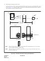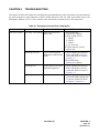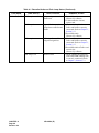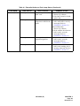
1
ND-46550 (E)
ISSUE 2
STOCK # 151944
®
Remote PIM System Manual
SEPTEMBER, 1998
NEC America, Inc.
LIABILITY DISCLAIMER
NEC America Inc. reserves the right to change the specifications,
functions, or features, at any time, without notice.
NEC America Inc. has prepared this document for use by its employees and customers. The information contained herein is the
property of NEC America Inc. and shall not be reproduced without
prior written approval from NEC America Inc.
NEAX and Dterm are registered trademarks of NEC Corporation.
Copyright 1998
NEC America, Inc.
Printed in the U.S.A.
ND-46550 (E)
ISSUE 2
SEPTEMBER, 1998
NEAX2000 IVS
Remote PIM System Manual
TABLE OF CONTENTS
Page
LIST OF FIGURES.............................................................................................................................................
iii
LIST OF TABLES...............................................................................................................................................
v
CHAPTER 1
INTRODUCTION .................................................................................................................
1
1.
OUTLINE OF THIS MANUAL ................................................................................................................
1
2.
REFERENCE MANUALS.......................................................................................................................
1
CHAPTER 2
SYSTEM DESCRIPTION ....................................................................................................
3
1.
SYSTEM OUTLINE................................................................................................................................
3
2.
PIM CONFIGURATION..........................................................................................................................
4
3.
SYSTEM CONFIGURATION .................................................................................................................
5
4.
REQUIRED EQUIPMENT......................................................................................................................
6
5.
SYSTEM CAPACITY .............................................................................................................................
8
6.
SYSTEM CONDITIONS.........................................................................................................................
9
7.
TIME SLOT ALLOCATION ....................................................................................................................
10
CHAPTER 3
INSTALLATION ...................................................................................................................
13
1.
PRECAUTION IN HANDLING ...............................................................................................................
13
2.
INSTALLATION PROCEDURE..............................................................................................................
16
2.1
Installation Procedure for Main Site .......................................................................................................
18
2.1.1
Switch Setting of DAIA Card .....................................................................................................
18
2.1.2
Mounting of DAIA Card .............................................................................................................
23
2.1.3
Switch Setting of DAIC Card .....................................................................................................
24
2.1.4
Mounting of DAIC Card .............................................................................................................
28
2.1.5
BUS Cable Connection .............................................................................................................
29
Installation Procedure for Remote Site ..................................................................................................
34
2.2.1
Switch Setting of DAIB Card .....................................................................................................
34
2.2.2
Mounting of DAIB Card .............................................................................................................
39
2.2.3
Switch Setting of DAIC Card .....................................................................................................
41
2.2.4
Mounting of DAIC Card .............................................................................................................
41
2.2.5
BUS Cable Connection .............................................................................................................
44
2.2
ND-46550 (E)
TABLE OF CONTENTS
Page i
Revision 2.0
TABLE OF CONTENTS (CONTINUED)
Page
2.3
2.4
2.2.6
Mounting of Line/Trunk Card on Small Platform PIM................................................................
45
2.2.7
Mounting of Line/Trunk Card on 1000 IVS PIM ........................................................................
48
2.2.8
Mounting of Line/Trunk Card on PIM N - UB (64 port PIM) ......................................................
51
2.2.9
Power Failure Transfer (PFT) ...................................................................................................
54
Connection Between Main Site and Remote Site ..................................................................................
62
2.3.1
DTI Connection at Main Site .....................................................................................................
62
2.3.2
DTI Connection at Remote Site ................................................................................................
65
MP Reset ...............................................................................................................................................
66
CHAPTER 4
TROUBLESHOOTING ........................................................................................................
TABLE OF CONTENTS
Page ii
Revision 2.0
ND-46550 (E)
67
LIST OF FIGURES
Figure
Title
Page
2-1
Remote PIM System Outline ..............................................................................................................
3
2-2
System Configuration .........................................................................................................................
5
2-3
Time Slot Allocation ............................................................................................................................
10
2-4
Time Slot Allocation (Continued) ........................................................................................................
11
3-1
Static Electricity Guard .......................................................................................................................
13
3-2
Static-Sensitive Attention Symbol.......................................................................................................
14
3-3
Installation Procedure for Main Site ....................................................................................................
16
3-4
Installation Procedure for Remote Site ...............................................................................................
17
3-5
PN-DAIA Card ....................................................................................................................................
18
3-6
Mounting Location of DAIA Card ........................................................................................................
23
3-7
PN-DAIC Card ....................................................................................................................................
24
3-8
Mounting Location of DAIC Card (Main Site)......................................................................................
28
3-9
BUS-DAIA Cable Connection .............................................................................................................
29
3-10
DAIA-DAIC Cable Connection ............................................................................................................
30
3-11
DAIA-DAIC Cable Connection (Continued) ........................................................................................
31
3-12
DAIA-DAIC Cable Connection (Continued) ........................................................................................
32
3-13
DAIA-DAIC Cable Connection (Continued) ........................................................................................
33
3-14
PN-DAIB Card ....................................................................................................................................
34
3-15
Mounting Location of DAIB Card ........................................................................................................
39
3-16
Mounting Location of DAIB Card (Continued) ....................................................................................
40
3-17
Mounting Location of DAIC Card (Remote PIM).................................................................................
41
3-18
Mounting Location of DAIC Card (Remote PIM) (Continued) .............................................................
42
3-19
Mounting Location of DAIC Card (Remote PIM) (Continued) .............................................................
43
3-20
DAIB-DAIC Cable Connection ............................................................................................................
44
3-21
Mounting Location of Line/Trunk Card (Small Platform) .....................................................................
45
3-22
Location of Each LEN (Small Platform) ..............................................................................................
46
3-23
LTC Connector Pin Arrangement (Small Platform).............................................................................
47
3-24
Mounting Location of Line/Trunk Card (1000 IVS) .............................................................................
48
3-25
Location of Each LEN (1000 IVS).......................................................................................................
49
3-26
LTC Connector Pin Arrangement (1000 IVS) .....................................................................................
50
3-27
Mounting Location of Line/Trunk Card................................................................................................
51
3-28
Location of Each LEN (PIM N_UB).....................................................................................................
52
3-29
LTC Connector Pin Arrangement (PIM B - UB) ..................................................................................
53
3-30
PFT Connection Outline (PN-AUCA) ..................................................................................................
54
3-31
MDF Cross Connection for PFT (PN-AUCA) ......................................................................................
55
3-32
PFT (PZ-8PFTA) Connection Outline .................................................................................................
56
ND-46550 (E)
LIST OF FIGURES
Page iii
Revision 2.0
LIST OF FIGURES (CONTINUED)
Figure
Title
3-33
Connection of 25-Pair Cable and PZ-8PFTA......................................................................................
57
3-34
Mounting PZ-8PFTA Card to PIM.......................................................................................................
58
3-35
PFT Connector Pin Assignment .........................................................................................................
59
3-36
MDF Cross Connection for PFT (PZ-8PFTA) .....................................................................................
60
3-37
DTI Cable Connection via LTC Connector .........................................................................................
62
3-38
Example of DTI Cable Connection via LTC Connector ......................................................................
63
3-39
DTI Cable Connection via CN Connector (Main Site).........................................................................
64
3-40
DTI Cable Connection via CN Connector (Remote Site) ....................................................................
65
LIST OF FIGURES
Page iv
Revision 2.0
Page
ND-46550 (E)
LIST OF TABLES
Table
Title
Page
2-1
PIM Configuration ...............................................................................................................................
4
2-2
Required Equipment ...........................................................................................................................
6
2-3
System Capacity.................................................................................................................................
8
3-1
Lamp Indications on PN-DAIA Card ...................................................................................................
19
3-2
Switch Settings on PN-DAIA Card ....................................................................................................
20
3-3
Switch Settings When Clock Signal Supplied From Master Office .....................................................
22
3-4
Lamp Indications on PN-DAIC Card ...................................................................................................
25
3-5
Switch Settings on PN-DAIC Card .....................................................................................................
25
3-6
Lamp Indications on PN-DAIB Card ...................................................................................................
35
3-7
Switch Settings on PN-DAIB Card .....................................................................................................
36
3-8
LTC Connector Accommodation (Small Platform) ..............................................................................
45
3-9
LTC Connector Accommodation (1000 IVS) ......................................................................................
48
3-10
LTC Connector Accommodation.........................................................................................................
51
4-1
Remedial Action on Each Lamp Status .............................................................................................
67
ND-46550 (E)
LIST OF TABLES
Page v
Revision 2.0
This page is for your notes.
LIST OF TABLES
Page vi
Revision 2.0
ND-46550 (E)
CHAPTER 1
1.
INTRODUCTION
OUTLINE OF THIS MANUAL
This manual provides the system description and installation procedure for providing the Remote PIM System to
the NEAX2000 IVS.
2.
REFERENCE MANUALS
Refer to the following manuals for additional information on equipment and programming installation:
• Installation Procedure Manual
• Small Platform System Manual
• Circuit Card Manual
• Command Manual
• Office Data Programming Manual
• Maintenance Manual
ND-46550 (E)
CHAPTER 1
Page 1
Revision 2.0
This page is for your notes.
CHAPTER 1
Page 2
Revision 2.0
ND-46550 (E)
CHAPTER 2
1.
SYSTEM DESCRIPTION
SYSTEM OUTLINE
Remote PIMs can be installed separately in the same building or between the offices via the Public Switching
Telephone Network (PSTN).
The customers in the remote site can use the same service features as in the main site. Remote PIMs are connected
to the main site by T1 (1.5 Mbps) digital interface.
Figure 2-1 shows an outline of the Remote PIM System.
PIM
1.5
M
)
(T 1
OFFICE B
(Remote Site)
NEAX2000 IVS
PIM
OFFICE A
(Main Site)
PIM
1.5M (T1)
1.5
M
OFFICE C
(Remote Site)
(T1
)
PIM
OFFICE D
(Remote Site)
Figure 2-1
Note:
Remote PIM System Outline
The remote PIM contains station and trunk cards. A CPU card is not required in the remote offices.
ND-46550 (E)
CHAPTER 2
Page 3
Revision 2.0
2.
PIM CONFIGURATION
One PIM can be installed respectively as a remote site. A maximum of 3 remote sites can be provided. The number
of remote sites determines the number of PIMs in one system. Table 2-1 shows the available PIM configuration for
the Remote PIM System.
Table 2-1 PIM Configuration
NUMBER OF PIM AT MAIN SITE
AVAILABLE NUMBER OF REMOTE SITE
1 PIM
(1 FP)
1
2
3
2 PIM
(1 FP)
1
2
3
3 PIM
(2 FP)
1
2
_
4 PIM
(2 FP)
1
2
_
5 PIM
(3 FP)
1
_
_
6 PIM
(3 FP)
1
_
_
7 PIM
(4 FP)
_
_
_
8 PIM
(4 FP)
_
_
_
CHAPTER 2
Page 4
Revision 2.0
ND-46550 (E)
3.
SYSTEM CONFIGURATION
Figure 2-2 shows the system configuration.
Main Site
Remote Site
Remote PIM 1
DAIA 1
(FP1)
23 B Channel
1 D Channel
DAIB
(FP1)
Line/TRK
24 B Channel
DAIC 1
DAIC 1
24 B Channel
DAIC 2
DAIC 2
Remote PIM 2
DAIA 2
(FP2)
TDSW
DAIC 3
DAIC 4
23 B Channel
1 D Channel
24 B Channel
24 B Channel
DAIB
(FP2)
Line/TRK
DAIC 3
DAIC 4
Remote PIM 3
DAIA 3
(FP3)
23 B Channel
1 D Channel
DAIB
(FP3)
Line/TRK
24 B Channel
DAIC 5
DAIC 6
MP
DAIC 5
24 B Channel
DAIC 6
FP0
Figure 2-2
System Configuration
ND-46550 (E)
CHAPTER 2
Page 5
Revision 2.0
4.
REQUIRED EQUIPMENT
Table 2-2 shows the required equipment for establishing the Remote PIM System.
Table 2-2 Required Equipment
EQUIPMENT NAME
SN1308 PIM P-A (PIM Q-UA)
DESCRIPTION
Port Interface Module for Small Platform System/Remote PIM system
(remote site)
A PIM provides 13 card slot for common control, Line/Trunk cards. It
also houses a AC/DC power supply and optional batteries for protection
from short-term power interruption.
Three champ connectors for line/trunk (LTC0 to 2) and a connector for
Power (PWR) are located at the lower front side of the PIM.
SN1420 PIMAB-A
Port Interface Module (PIM) for 1000 IVS/Remote PIM system (remote
site).
A PIM provides 10 card slots for common control, Line/Trunk, and
Application Processor (AP) cards. It is also houses a AC/DC Power Supply and batteries for protection from short-term power interruption.
Two champ connectors for line/trunk (LTC0 to 1) and a connector for
Power (PWR) are located at the lower front side of the PIM.
PN-DAIA (DAIA Card)
Interface card for Remote PIM System at main site
This card provides 1.5 Mbps (24 channel) digital interface, firmware
processor, and BUS interface; 1 through 3 DAIA cards must be provided
at main site, which corresponds to the number of the remote site.
PN-DAIB (DAIB Card)
Interface card for the Remote PIM System at remote site
This card provides 1.5 Mbps (24 channel) digital interface, firmware
processor; 1 card is required per Remote PIM at the remote site.
PIM N-UB
Port Interface Module for 128/512 port systems/Remote PIM system.
This PIM can be a Remote PIM or main office PIM.
This PIM provides 19 slots for common control line and trunk cards. This
PIM houses an AC/DC power supply and optional batteries for short-term
power interruption.
Three champ connectors for line/trunk (LTC0 to 2) and a connector for
Power (PWR) are located at the lower front side of the PIM.
CHAPTER 2
Page 6
Revision 2.0
ND-46550 (E)
Table 2-2 Required Equipment (Continued)
EQUIPMENT NAME
PN-DAIC (DAIC Card)
DESCRIPTION
Digital Interface Channel Expansion Card.
This card provides the 1.5Mbps (24 channel) digital interface.
1 through 6 DAIC cards can be provided at main site.
In Remote PIM, 2 DAIC cards can be provided.
Small Platform PIM: up to 64 line/trunks can be accommodated.
1000 IVS PIM: up to 47 line/trunks can be accommodated.
PN-BS00/BS01 (BUS interface Card) BUS interface cards for PIM0 or PIM1 through PIM7
For Remote PIM System, BS00 card is required at the main site, even if
the system is 1-PIM configuration.
PN-CP01 (FP Card)
Firmware processor card
For Remote PIM System, CP01 card must be mounted on PIM0 at the
main site, even if the system is 1-PIM configuration.
RMT PCM-0.3 CA
1 ft. (30 cm) PCM signal cable
This cable is used for connection between DAIA card and BUS interface
card.
17-TW-0.3 CONN CA-A
1 ft. (30 cm) connection cable between DAIA cards
This cable is required when plural DAIA cards are mounted in a PIM at
the main site.
48-TW-0.2 CONN CA
1ft. (30 cm) connection cable.
This cable is used for connecting between DAIA card and DAIC card or
DAIB card and DAIC card.
ND-46550 (E)
CHAPTER 2
Page 7
Revision 2.0
5.
SYSTEM CAPACITY
Table 2-3 shows the system capacity.
Table 2-3 System Capacity
CAPACITY
MAIN PIM
DESCRIPTION
REMOTE PIM
REMARKS
2000 IVS
SMALL
PLATFORM
(72 Port)
1000 IVS
(48 Port)
Max. number of DAIA card
3
-
-
Max. number of DAIB card
-
1
1
Max. number of DAIC card
6
2
1
Max. number of ports on
Remote Site
-
24
24
Note 1
Note 1
48
48
Note 1
Note 1
64
Note 1
-
Number of PIM
1, 2
3, 4
5, 6
7, 8
3
3
Note 2
2
2
Note 2
Note 2
1
Main PIM :DAIA
Remote PIM :DAIB
Main PIM :1 DAIA, 2 DAIC
Remote PIM :1 DAIB, 2 DAIC
Main PIM :1 DAIA, 2 DAIC
Remote PIM :1 DAIB, 2 DAIC
Number of PIM depends on the
number of Main PIM and
Remote PIM. (Refer to Chapter,
Section 2.)
1
Note 2
0
0
Note 3
Note 3
Note 1:
1 port is used for the control signaling channel.
Note 2:
This number refers to the maximum number of remote offices. The remote office can have only one remote PIM.
Note 3:
When the main site consists of 7 or 8 PIMs, a Remote PIM cannot be provided.
CHAPTER 2
Page 8
Revision 2.0
ND-46550 (E)
6.
SYSTEM CONDITIONS
For providing the Remote PIM System to the NEAX2000 IVS, observe the following conditions:
(1)
The main site must be the NEAX2000 IVS. The Small Platform System cannot be the main site. The main
site must be a medium platform (320 ports) or a large platform (512 ports). The small platform (72 ports)
cannot be used.
(2)
The Remote PIM can be a PIM N-UB, a PIM Q-UA, or a PIM AB-A.
(3)
The Remote PIM can be installed at a maximum of 1312 ft. (399 m) distance from the main site. Using line
extension equipment (repeater, MUX etc.), the distance can be extended.
(4)
A maximum of 23 lines/trunks can be accommodated in one Remote PIM.
(5)
On the remote site, the line/trunk circuit cards can be used as same as the main site, except the CSI card for
wireless system according to UTAM regulation. However, the application circuit cards cannot be used at the
remote site. When providing the ILC card to the remote site, the ICH card must be installed on the main site.
(6)
For the Remote PIM System, the installation procedures for modules, circuit cards and peripheral equipment
are the same as those for the regular NEAX2000 IVS, except the DAIA card and the DAIB card installation
and the BUS cable connection. Refer to the applicable manuals for detailed information.
(7)
When the link between the main site and the remote site is lost, the system activates PFT (Power Failure
Transfer) automatically on the remote site, if provided.
(8)
The resident system programming cannot be set to the remote site while the main site can be set.
(9)
When the LC cards that use an AP card directly (i.e., ILC requires ICH, and 4COTB requires 4RSTC.) If ILC
or COTB are mounted in the Remote PIM, the T1 link between the main and remote sites must be configured
as 64 Kbps with ESF and B8ZS.
(10) In the remote site, if the Remote PIM is a 72-port PIM or a 48-port PIM, when installing a 4-circuit card (LC,
DLC, COT, etc.), assign a phantom DK00 to Level 4 and Level 6 of that LT slot. This assignment will shift
the time slots over enabling the use of additional card slots. (This action is not required if the Remote PIM is
a 64-port PIM.)
ND-46550 (E)
CHAPTER 2
Page 9
Revision 2.0
7.
TIME SLOT ALLOCATION
One time slot of the last 24 time slots provided by the DAIA-DAIB connection is used for the control signaling
channels. Figure 2-3 shows an example of time slot allocation when mounting 8 port cards to the Small Platform
PIM.
(1) When using 1 DAIA card and 1 DAIB card
LT10
LT09
LT08
LT07
LT06
LT05
LT04
LT03
LT02
LT01
LT00
Remote Site
Highway Channel 00-23
DAIB
• 23 time slots for Line/Trunks
• 1time slot for control signaling
channel
Note
DAIA
TDSW
Main Site
(2) When using 1 DAIA card, 1 DAIB card, and 2 DAIC cards.
LT10
LT09
LT08
LT07
LT06
LT05
LT04
LT03
LT02
LT01
LT00
Remote Site
Highway Channel 00-23
24-47
DAIC
DAIB
• 24 time slots for Line/Trunks
• 23 time slots for Line/Trunks
• 1time slot for control signaling
channel
Note
• Max. 47 time slots for Line/Trunks
per Remote Site
DAIC
DAIA
Main Site
Note:
The control signalling channel is set by SW2 of DAIA/DAIB. Refer to Chapter 3 sections 2.1.1
and 2.2.1 for the switch settings.
Figure 2-3
CHAPTER 2
Page 10
Revision 2.0
TDSW
Time Slot Allocation
ND-46550 (E)
(3) When using 1 DAIA card, 1 DAIB card, and 4 DAIC cards
LT10
LT09
LT08
LT07
LT06
LT05
LT04
LT03
LT02
LT01
LT00
Remote Site
Highway Channel 00-23
24-47 48-63
DAIC 0 DAIC 1 DAIB
• 24 time slots for Line/Trunks
• 23 time slots for Line/Trunks
• 1 time slot for control signaling
channel
Note
• 24 time slots for Line/Trunks
• Max. 64 time slots for Line/Trunks
per Remote Site
DAIC 0 DAIC 1 DAIA
Main Site
Note:
TDSW
The control signalling channel is set by SW2 of DAIA/DAIB card. Refer to Chapter 3 sections 2.1.1 and
2.2.1 for the switch settings.
Figure 2-4
Time Slot Allocation (Continued)
ND-46550 (E)
CHAPTER 2
Page 11
Revision 2.0
This page is for your notes.
CHAPTER 2
Page 12
Revision 2.0
ND-46550 (E)
CHAPTER 3
1.
INSTALLATION
PRECAUTION IN HANDLING
When handling cards, the installer must wear a grounded wrist strap to protect the circuit card from static
electricity, and the installer must engage in the work on a grounded conductive work surface. Figure 3-1 illustrates
the actions to take while handling circuit cards.
• When plugging/unplugging circuit card
PBX
WRIST STRAP
FRAME GROUND SCREW
Connect ground wire to
frame earth of equipment.
• When holding circuit card
Never touch components
or soldered surface with
bare hands.
CARD FRONT
Figure 3-1
Static Electricity Guard
ND-46550 (E)
CHAPTER 3
Page 13
Revision 2.0
• When setting switches on circuit card
CIRCUIT
CARD
Wear a wrist strap and perform work on a grounded
conductive work surface.
• When carrying circuit card
CIRCUIT
CARD
CONDUCTIVE
POLYETHYLENE
BAG
When carrying a circuit card around,
keep the card in a conductive
polyethylene bag.
Figure 3-1
Static Electricity Guard (Continued)
The symbol shown in Figure 3-2 designates procedures in which circuit cards are handled. When engaging in such
work, the installer must be careful not to cause damage by static electricity.
ATTENTION
Contents
Static Sensitive
Handling
Precautions Required
Figure 3-2
CHAPTER 3
Page 14
Revision 2.0
Static-Sensitive Attention Symbol
ND-46550 (E)
CAUTION
When plugging or unplugging the circuit card, always hold the circuit card by its edge. If you touch another area,
you may be exposed to hazardous voltages.
PBX
Never touch components or
soldered surface with bare hands.
CARD FRONT
ND-46550 (E)
CHAPTER 3
Page 15
Revision 2.0
2.
INSTALLATION PROCEDURE
Install the Remote PIM System according to the following procedure. Figure 3-3 and Figure 3-4 show the
installation procedure for the main site and the remote site.
START
Switch Setting of DAIA Card
See Section 2.1.1
Mounting of DAIA Card
See Section 2.1.2
Switch Setting of DAIC Card
Mounting of DAIC Card
Mounting of BS00 Card
Mounting of CP01 Card
BUS Cable Connection
Connection Between
Main Site and Remote Site
See Section 2.1.3
See Section 2.1.4
See Installation Procedure Manual
and Circuit Card Manual.
* These procedures are required even if the main
site is 1-PIM configuration.
See Section 2.1.5
See Section 2.3
See Section 2.4
MP Reset
END
Note:
For the main site, this manual describes only the installation procedure exclusively required for the
Remote PIM System. Refer to the Installation Procedure Manual for regular installation.
Figure 3-3
CHAPTER 3
Page 16
Revision 2.0
Installation Procedure for Main Site
ND-46550 (E)
START
Unpacking*
Marking and Drilling*
Installation of Main Equipment
Cable Running to MDF*
Connection of Battery*
Switch Setting of DAIB Card
See Section 2.2.1
Mounting of DAIB Card
See Section 2.2.2
Switch Setting of DAIC Card
See Section 2.1.3
Mounting of DAIC Card
See Section 2.2.4
Termination of Cables on MDF*
Connection between
Main Site and Remote Site
MP Reset
See Section 2.3
See Section 2.4
System Initialization
and System Data Entry*
Switch Setting of
Line/Trunk Circuit Cards*
Operation Test*
Mounting of
Line/Trunk Circuit Cards
Power Failure Transfer (PFT)
See Section 2.2.6
See Section 2.2.7
See Section 2.2.9
Cleaning and Visual Check*
Mounting of Front Cover*
Note 2
END
Note 1:
This manual describes only the installation procedure exclusively required for the Remote PIM
System. Refer to the Installation Procedure Manual for the procedures marked by * .
Note 2:
It is recommended that the Power Failure Transfer (PFT) is provided on the Remote Site in case
the link between the main site and the remote site is lost.
Figure 3-4
Installation Procedure for Remote Site
ND-46550 (E)
CHAPTER 3
Page 17
Revision 2.0
2.1 Installation Procedure for Main Site
2.1.1 Switch Setting of DAIA Card
(1)
Location of Lamps, Switches, and Connectors (see Figure 3-5)
ATTENTION
Contents
Static Sensitive
Handling
Precautions Required
SENSE
RUN
MB
LINK
RED
RMT
LOOP
PWR
BL
SW1
SW2
BUS
SW3
PCM1
JPS
PCM0
JPR
CN
Figure 3-5
CHAPTER 3
Page 18
Revision 2.0
PN-DAIA Card
ND-46550 (E)
(2)
Lamp Indications (see Table 3-1)
Table 3-1 Lamp Indications on PN-DAIA Card
LAMP NAME
COLOR
FUNCTION
RUN
Green
Flashes at 120 IPM while this card is operating normally.
LINK
Green
Lights when a link between this card and a distant office is connected
normally. Goes out after 15 seconds of link disconnection.
RED
Red
Lights when detecting PCM signal loss or Frame Alignment signal loss.
RMT
Red
Lights when receiving a alarm signal from a distant office.
LOOP
–
Not used
PWR
–
Not used
BL
Red
Lights while data transmission on control channel (D ch). Flashes while FP
data downloading.
ND-46550 (E)
CHAPTER 3
Page 19
Revision 2.0
(3)
Switch Settings
In Table 3-2, the figure in the SWITCH NAME column and the position in
in the SETTING POSITION column indicate the standard setting of the switch. When the switch is not set as shown by the figure
and
, the setting of the switch varies with the system concerned.
Table 3-2 Switch Settings on PN-DAIA Card
SWITCH
NAME
SWITCH SETTING
NUMBER POSITION
SW1 (Rotary
SW)
0–F
1
2
3
Note 1
Note 2
FUNCTION
FP (Firmware Processor) Number setting for DAIA card.
By this setting, system regards DAIA card and the opposite DAIB
card as one firmware processor.
0
Not used
1
FP No. 1
2
FP No. 2
3
FP No. 3
4–F
Not used
UP
For make-busy
OFF
For normal operation
1
ON
For supplying 1.5 MHz clock to PLO 0
Note 4
OFF
No clock supply to PLO 0
2
ON
For supplying 1.5 MHz clock to PLO 1
Note 4
OFF
No clock supply to PLO 1
3
OFF
Always set to OFF
4
OFF
Always set to OFF
MB (Toggle SW)
ON
Note 3
SW1 (Piano Key
SW)
OFF
4
3
2
1
ON
CHAPTER 3
Page 20
Revision 2.0
ND-46550 (E)
CHECK
Table 3-2 Switch Settings on PN-DAIA Card (Continued)
SWITCH
NAME
SW2 (Dip SW)
ON
SWITCH SETTING
NUMBER POSITION
1
1 2345 678
2
3
4
FUNCTION
ON
Control channel signaling data transmission speed:
48 Kbps
OFF
Control channel signaling data transmission speed:
64 Kbps
ON
DTI frame configuration: 12-Multi Frame
OFF
DTI frame configuration: 24-Multi Frame
ON
Line code: AMI with ZCS
OFF
Line code: B8ZS
ON
Setting of control signal time slot
SWITCH NUMBER
OFF
5
ON
OFF
6
ON
OFF
7
ON
OFF
8
CHECK
ON
OFF
4
5
6
7
8
TIME SLOT
NUMBER
OFF
ON
OFF
ON
OFF
ON
OFF
ON
OFF
ON
OFF
ON
OFF
ON
OFF
ON
OFF
ON
OFF
OFF
ON
OFF
OFF
ON
ON
OFF
OFF
ON
ON
OFF
OFF
ON
ON
OFF
OFF
ON
ON
OFF
OFF
OFF
ON
ON
ON
OFF
OFF
OFF
OFF
ON
ON
ON
ON
OFF
OFF
OFF
OFF
ON
ON
ON
ON
OFF
ON
ON
ON
ON
ON
ON
ON
OFF
OFF
OFF
OFF
OFF
OFF
OFF
OFF
ON
ON
ON
ON
ON
ON
ON
ON
ON
ON
ON
ON
ON
ON
ON
ON
ON
ON
ON
ON
OFF
OFF
OFF
OFF
OFF
TS1
TS2
TS3
TS4
TS5
TS6
TS7
TS8
TS9
TS10
TS11
TS12
TS13
TS14
TS15
TS16
TS17
TS18
TS19
TS23
* Time slot number 0, 20, 21, and 22 (TS0/20/21/22)
cannot be used for control signal.
** This setting must be identical with the opposite
DAIB card.
ND-46550 (E)
CHAPTER 3
Page 21
Revision 2.0
Table 3-2 Switch Settings on PN-DAIA Card (Continued)
SWITCH
NAME
SWITCH SETTING
NUMBER POSITION
SW3 (Dip SW)
1
ON
OFF
ON
1
2
3
FUNCTION
Set equalizer according to cable length between
system and CSU.
SW-1 SW-2 SW-3
4
2
ON
ON
ON
ON
ON
OFF
OFF
OFF
3
ON
OFF
4
JPS (Jumper pin)
JPR (Jumper pin)
CHECK
ON
ON
OFF
OFF
ON
OFF
CABLE LENGTH
ON
OFF
ON
OFF
ON
OFF
0 - 131.2 ft. (0 - 40 m)
131.2 - 262.5 ft. (40 - 80 m)
262.5 - 394 ft. (80 - 120 m)
394 - 525 ft. (120 - 160 m)
525 - 656 ft. (160 - 200 m)
Signal is not sent
OFF
Always set to OFF
Right
For mounting this card on PIM1 ~ PIM7
Left
For mounting this card on PIM0
Right
Neutral grounding on the receiving line is provided.
Left
Neutral grounding on the receiving line is not
provided.
Note 1:
Set the groove on the switch knob to the desired switch position.
Note 2:
Since DAIA card acts like an FP, the SW1 for DAIA in FPs cannot be set to the same number.
Note 3:
When power is on, flip MB switch to ON (UP position) before plugging/unplugging the circuit card.
Note 4:
When the clock signal from a master office is supplied via the line between the Main Site and the Remote
Site, set the SW1-1 and SW1-2 according to settings in Table 3-3. In this case, DAIA cards (DAIA0,
DAIA1) must be mounted in PIM0.
Table 3-3 Switch Settings When Clock Signal Supplied From Master Office
DAIA0
DAIA1
DAIA2
CONDITIONS
REMARKS
SW1-1
SW1-2
SW1-1
SW1-2
SW1-1
SW1-2
Only one DAIA
card is provided.
ON
OFF
-
-
-
-
Clock signal is sent to
PLO0 of MP card via
supply route 0 (DAIA0).
Two or three DAIA
cards are provided.
ON
OFF
OFF
ON
OFF
OFF
Clock signal supply route
is automatically changed
to route 1 (DAIA1) if
transmission line failure
occurs on supply route 0.
CHAPTER 3
Page 22
Revision 2.0
ND-46550 (E)
2.1.2 Mounting of DAIA Card
STEP 1: Set MB switch on the DAIA card to up position.
ATTENTION
STEP 2: Mount DAIA card in the AP slots (AP0-AP7) on the Main Site PIM0-PIM5.
A maximum of three DAIA cards can be mounted. Figure 3-6 shows
the mounting location of the DAIA card.
Contents
Static Sensitive
Handling
Precautions Required
On the multiple PIM configuration, the DAIA card(s) must be mounted on the
first/last PIM due to the number of connectors of a BUS card.
After mounting the card, set MB switch to down position.
BUS/AP8
PWR
LT15/AP6
MP/FP/AP7
LT14/AP5
LT14/AP4
LT13/AP3
LT12/AP2
LT11/AP1
LT10/AP0
LT09
LT08
LT07
LT05
LT06
LT04
LT02
LT03
LT00
LT01
Main Site
PIM0-PIM5
*
DAIA CARD
Note 1:
For mounting the DAIA card on the slot marked * , the CN connector on the DAIA card should be
used.
Note 2:
When the clock signal is supplied from a master office, Mount DAIA cards (DAIA0, DAIA1) in
PIM0 in order to receive the clock signal.
Figure 3-6
Mounting Location of DAIA Card
ND-46550 (E)
CHAPTER 3
Page 23
Revision 2.0
2.1.3 Switch Setting of DAIC Card
(1)
Location of Lamps, Switches, and Connectors (See Figure 3-7.)
RUN
MB
LINK
RED
RMT
LOOP
PWR
BL
SW1
SW2
TBUS
SW3
RBUS
CN
Figure 3-7
CHAPTER 3
Page 24
Revision 2.0
PN-DAIC Card
ND-46550 (E)
(2)
Lamp Indications (SeeTable 3-4.)
Table 3-4 Lamp Indications on PN-DAIC Card
(3)
LAMP NAME
COLOR
FUNCTION
RUN
Green
Flashes at 120 IPM while this card is operating normally.
LINK
Green
Lights when the following connections are normal.
• Control channel link between the DAIA card and DAIB
card.
• Connection between the opposite DAIC card.
Goes out after 15 seconds of link disconnection.
RED
Red
Lights when detecting PCM signal loss or Frame Alignment
signal loss.
RMT
Red
Lights when receiving an alarm signal from a distant office.
LOOP
–
Not used
PWR
–
Not used
BL
–
Not used
Switch Settings
Table 3-5 Switch Settings on PN-DAIC Card
SWITCH NAME
SWITCH
NUMBER
MB (Toggle SW)
SETTING
POSITION
UP
FUNCTION
CHECK
For make-busy
ON
DOWN
Note
SW1 (Piano Key
SW)
1
Always set to OFF
OFF
2
OFF
For normal operation
Always set to OFF
OFF
4
3
3
Always set to OFF
OFF
2
1
4
ON
Always set to OFF
OFF
ND-46550 (E)
CHAPTER 3
Page 25
Revision 2.0
Table 3-5 Switch Settings on PN-DAIC Card (Continued)
SWITCH NAME
SWITCH
NUMBER
SW2 (Dip SW)
1
OFF
Not used
2
ON
DTI frame configuration: 12-Multi
Frame
ON
SETTING
POSITION
1234 5 678
OFF
3
CHAPTER 3
Page 26
Revision 2.0
FUNCTION
DTI frame configuration: 24-Multi
Frame
ON
Line code: AMI with ZCS
OFF
Line code: B8ZS
4
OFF
Not used
5
OFF
Not used
6
OFF
Not used
7
OFF
Not used
8
OFF
Not used
ND-46550 (E)
CHECK
Table 3-5 Switch Settings on PN-DAIC Card (Continued)
SWITCH NAME
SWITCH
NUMBER
SW3 (Dip SW)
1
SETTING
POSITION
ON
OFF
ON
1
2
3
4
FUNCTION
Set the equalizer according to the cable
length between the system and the CSU.
SW-1 SW-2 SW-3
2
ON
OFF
3
ON
CHECK
ON
ON
ON
ON
OFF
OFF
ON
ON
OFF
OFF
ON
OFF
ON
OFF
ON
OFF
ON
OFF
CABLE LENGTH
0 - 131.2 ft (0 - 40 m)
131.2 - 262.5 ft. (40 - 80 m)
262.5 - 394 ft. (80 - 120 m)
394 - 525 ft. (120 - 160 m)
525 - 656 ft. (160 - 200 m)
Signal is not sent
OFF
4
ON
When mounting this card on remote
site.
OFF
When mounting this card on main site.
In Table 3-5, the figure in the SWITCH NAME column and the position in
in the SETTING
POSITION column indicate the standard setting of the switch. When the switch is not set as shown by the
figure and
Note:
, the setting of the switch varies with the system concerned.
When the power is on, flip the MB switch to ON (UP position) before plugging/unplugging the circuit card.
ND-46550 (E)
CHAPTER 3
Page 27
Revision 2.0
2.1.4 Mounting of DAIC Card
STEP 1: Set MB switch on the DAIC card to up position.
ATTENTION
STEP 2: Mount DAIC card in the AP slots (AP0-AP7) to the LT slot (LT09)
on the Main Site PIM0-PIM5.
A maximum of six DAIC cards can be mounted.
After mounting the card, set MB switch to down position.
Contents
Static Sensitive
Handling
Precautions Required
STEP 3: After mounting all DAIC cards, set MB switch on DAIA card to up, and then down.
BUS/AP8
DAIC CARD
Figure 3-8
CHAPTER 3
Page 28
Revision 2.0
Mounting Location of DAIC Card (Main Site)
ND-46550 (E)
PWR
LT16/AP6
MP/FP/AP7
LT15/AP5
LT14/AP4
LT13/AP3
LT12/AP2
LT11/AP1
LT10/AP0
LT08
LT09
LT07
LT05
LT06
LT04
LT02
PIM0-PIM5
LT03
LT00
LT01
Main Site
2.1.5 BUS Cable Connection
(1)
Cable connection between BUS Card and the DAIA Card
Connect the DAIA card to the BUS card by the RMT PCM-0.3 CA and 17-TW-0.3 CONN CA-A, as shown in
Figure 3-9.
Note:
Up to three DAIA cards can be connected directly by a daisy chain connection on one PIM. If two or three
DAIA cards are mounted on one PIM, the 17-TW-0.3 CONN CA-A is required. When the system is more
than one PIM configuration, the DAIA cards must be mounted on the first/last PIM due to the number of
connectors of a BUS card.
(1) 1-PIM Configuration
: RMT PCM-0.3 CA
BS00
• When mounting 1 DAIA card
DAIA
DAIA
: 17-TW-0.3 CONN CA-A
BUS
CN2
PIM0
CN2
PCM1
PCM0
CN1
CN1
PCM1
PCM0
BS00
• When mounting 2 DAIA cards
DAIA DAIA
BUS
PIM0
DAIA
CN2
DAIA
CN1
PCM1
PCM0
PCM1
PCM0
BS00
• When mounting 3 DAIA cards
DAIA DAIA DAIA
DAIA
BUS
CN2
DAIA
PIM0
DAIA
CN1
PCM1
PCM0
PCM1
PCM0
Figure 3-9
BUS-DAIA Cable Connection
ND-46550 (E)
CHAPTER 3
Page 29
Revision 2.0
(2)
Cable Connection between DAIA Card and DAIC Card
Connect the DAIC card to the DAIA card by the 48-TW-0.2 CONN CA, as shown in Figure 3-10.
(1) 1-PIM Configuration
: RMT PCM-0.3 CA
• When mounting 1 DAIA card and 1 DAIC card
: 17-TW-0.3 CONN CA-A
: 48-TW-0.2 CONN CA
BUS
DAIC DAIA
PIM0
TBUS
CN2
PCM1
PCM0
RBUS
CN1
• When mounting 2 DAIA cards and 2 DAIC cards
DAIC DAIA
BUS
DAIC DAIA
PIM0
TBUS
CN2
PCM1
PCM0
RBUS
CN1
• When mounting 3 DAIA cards and 3 DAIC cards
DAIC DAIA
DAIC DAIA
DAIC DAIA
BUS
PIM0
TBUS
CN2
PCM1
PCM0
RBUS
Figure 3-10
CHAPTER 3
Page 30
Revision 2.0
CN1
DAIA-DAIC Cable Connection
ND-46550 (E)
(2) Multiple PIM Configuration
: RMT PCM-0.3 CA
• When mounting 1 DAIA card and 2 DAIC cards on upper PIM
BUS
DAIC DAIC DAIA
: 48-TW-0.2 CONN CA
: 48 TW-0.7 CONN CA
LAST PIM
TBUS
RBUS
CN2
CN1
PCM1
PCM0
PIM0
CN2
CN1
• When mounting 2 DAIA cards and 4 DAIC cards on 2 PIMs
BUS
DAIC DAIC DAIA
LAST PIM
TBUS
RBUS
CN2
CN1
PCM1
PCM0
PIM0
TBUS
RBUS
PCM1
PCM0
DAIC DAIC DAIA
Figure 3-11
CN2
CN1
BUS
DAIA-DAIC Cable Connection (Continued)
ND-46550 (E)
CHAPTER 3
Page 31
Revision 2.0
(2) Multiple PIM Configuration (continued)
: RMT PCM-0.3 CA
• When mounting 3 DAIA cards and 4 DAIC cards on 2 PIMs
DAIC DAIC DAIA
: 17-TW-0.3 CONN CA-A
: 48-TW-0.2 CONN CA
BUS
: 48 TW-0.7 CONN CA
LAST PIM
TBUS
RBUS
CN2
CN1
PCM1
PCM0
PIM0
TBUS
CN2
CN1
PCM1
PCM0
RBUS
DAIC DAIA
DAIC DAIA
BUS
• When mounting 3 DAIA cards and 5 DAIC cards on 2 PIMs
DAIC DAIC DAIA
BUS
LAST PIM
TBUS
RBUS
CN2
CN1
PCM1
PCM0
PIM0
TBUS
DAIC DAIC DAIA
Figure 3-12
CHAPTER 3
Page 32
Revision 2.0
CN2
CN1
PCM1
PCM0
RBUS
DAIC DAIA
BUS
DAIA-DAIC Cable Connection (Continued)
ND-46550 (E)
(2) Multiple PIM Configuration (continued)
: RMT PCM-0.3 CA
: 17-TW-0.3 CONN CA-A
• When mounting 3 DAIA cards and 6 DAIC cards on last PIM
: 48-TW-0.2 CONN CA
: 48 TW-0.7 CONN CA
DAIC DAIC DAIA DAIC DAIC DAIA DAIC DAIC DAIA BUS
LAST PIM
TBUS
CN2
CN1
RBUS
PCM1
PCM0
PIM0
CN2
CN1
BUS
Figure 3-13
DAIA-DAIC Cable Connection (Continued)
ND-46550 (E)
CHAPTER 3
Page 33
Revision 2.0
2.2 Installation Procedure for Remote Site
2.2.1 Switch Setting of DAIB Card
(1)
ATTENTION
Location of Lamps, Switches, and Connectors (see Figure 3-14)
Contents
Static Sensitive
Handling
Precautions Required
SENSE
RUN
MB
LINK
RED
RMT
SW1
LOOP
BL
SW2
BUS
SW3
JPS
JPR
CN
Figure 3-14
CHAPTER 3
Page 34
Revision 2.0
PN-DAIB Card
ND-46550 (E)
(2)
Lamp Indications (see Table 3-6)
Table 3-6 Lamp Indications on PN-DAIB Card
LAMP NAME
COLOR
FUNCTION
RUN
Green
Flashes at 120 IPM while this card is operating normally.
LINK
Green
Lights when a link between this card and a distant office is connected normally. Goes out after 15 seconds of link disconnection.
RED
Red
Lights when detecting PCM signal loss or Frame Alignment signal loss.
RMT
Red
Lights when receiving a alarm signal from a distant office.
LOOP
–
BL
Red
Not used
Lights while data transmission on control channel (D ch). Flashes while
FP data downloading.
ND-46550 (E)
CHAPTER 3
Page 35
Revision 2.0
(3)
Switch Settings
In Table 3-7, the figure in the SWITCH NAME column and the position in
in the SETTING POSITION column indicate the standard setting of the switch. When the switch is not set as shown by the figure
and
, the setting of the switch varies with the system concerned.
Table 3-7 Switch Settings on PN-DAIB Card
SWITCH
NAME
SWITCH
NUMBER
SW1 (Rotary
SW)
0–F
SETTING
POSITION
0
1–F
UP
MB (Toggle SW)
FUNCTION
Always set to 0
Not used
For make-busy
ON
OFF
For normal operation
OFF
Always set to OFF
OFF
Always set to OFF
OFF
Always set to OFF
OFF
Always set to OFF
Note
SW1 (Piano Key
SW)
1
2
OFF
4
3
3
2
1
4
ON
CHAPTER 3
Page 36
Revision 2.0
ND-46550 (E)
CHECK
Table 3-7 Switch Settings on PN-DAIB Card (Continued)
SWITCH
NAME
SWITCH
NUMBER
SETTING
POSITION
SW2 (Dip SW)
1
ON
ON
12345 678
OFF
2
3
4
FUNCTION
Control channel signaling data transmission speed:
48 Kbps
Control channel signaling data transmission speed:
64 Kbps
ON
DTI frame configuration: 12-Multi Frame
OFF
DTI frame configuration: 24-Multi Frame
ON
Line code: AMI with ZCS
OFF
Line code: B8ZS
ON
Setting of control signal time slot
SWITCH NUMBER
OFF
5
ON
OFF
6
ON
OFF
7
ON
OFF
8
CHECK
ON
4
5
6
7
8
TIME SLOT
NUMBER
OFF
ON
OFF
ON
OFF
ON
OFF
ON
OFF
ON
OFF
ON
OFF
ON
OFF
ON
OFF
ON
OFF
OFF
ON
OFF
OFF
ON
ON
OFF
OFF
ON
ON
OFF
OFF
ON
ON
OFF
OFF
ON
ON
OFF
OFF
OFF
ON
ON
ON
OFF
OFF
OFF
OFF
ON
ON
ON
ON
OFF
OFF
OFF
OFF
ON
ON
ON
ON
OFF
ON
ON
ON
ON
ON
ON
ON
OFF
OFF
OFF
OFF
OFF
OFF
OFF
OFF
ON
ON
ON
ON
ON
ON
ON
ON
ON
ON
ON
ON
ON
ON
ON
ON
ON
ON
ON
ON
OFF
OFF
OFF
OFF
OFF
TS1
TS2
TS3
TS4
TS5
TS6
TS7
TS8
TS9
TS10
TS11
TS12
TS13
TS14
TS15
TS16
TS17
TS18
TS19
TS23
* Time slot number 0, 20, 21, and 22 (TS0/20/21/22)
cannot be used for control signal.
OFF
** This setting must be identical with the opposite
DAIA card.
ND-46550 (E)
CHAPTER 3
Page 37
Revision 2.0
Table 3-7 Switch Settings on PN-DAIB Card (Continued)
SWITCH
NAME
SWITCH
NUMBER
SETTING
POSITION
SW3 (Dip SW)
1
ON
OFF
ON
1
2
3
4
2
ON
OFF
3
ON
OFF
4
JPS (Jumper pin)
OFF
UP
DOWN
JPR (Jumper pin)
UP
DOWN
Note:
FUNCTION
CHECK
Set the equalizer according to the cable length
between the system and the CSU.
SW-1
SW-2
SW-3
CABLE LENGTH
ON
ON
ON
ON
OFF
OFF
ON
ON
OFF
OFF
ON
OFF
ON
OFF
ON
OFF
ON
OFF
0 - 131.2 ft. (0 - 40 m)
131.2 - 262.5 ft. (40 - 80 m)
262.5 - 394 ft. (80 - 120 m)
394 - 525 ft. (120 - 160 m)
525 - 656 ft. (160 - 200 m)
Signal is not sent
Always set to OFF.
Neutral grounding on the transmitting line is
provided.
Neutral grounding on the transmitting line is not
provided.
Neutral grounding on the receiving line is provided.
Neutral grounding on the receiving line is not
provided.
When the power is on, flip the MB switch to ON (UP position) before plugging/unplugging the circuit card.
CHAPTER 3
Page 38
Revision 2.0
ND-46550 (E)
2.2.2 Mounting of DAIB Card
STEP 1: Set MB switch on the DAIB card to up position.
ATTENTION
STEP 2: Mount DAIB card in the MP slot on the Remote PIM.
Contents
Static Sensitive
Handling
Precautions Required
STEP 3: After mounting the card, set MB switch to down position.
•
Small Platform
MP
LT10
LT09
LT08
LT07
LT06
LT05
LT04
LT03
LT02
LT01
LT00
Remote PIM
P
W
R
DAIB CARD
Figure 3-15
Mounting Location of DAIB Card
ND-46550 (E)
CHAPTER 3
Page 39
Revision 2.0
ATTENTION
Contents
Static Sensitive
Handling
Precautions Required
• 1000 IVS
MP
LT08
LT07
LT06
LT05
LT04
LT03
LT02
LT01
LT00
Remote PIM
P
W
R
DAIB CARD
Figure 3-16
CHAPTER 3
Page 40
Revision 2.0
Mounting Location of DAIB Card (Continued)
ND-46550 (E)
2.2.3 Switch Setting of DAIC Card
Refer to Chapter 3, Section 2.1.3.
2.2.4 Mounting of DAIC Card
ATTENTION
Contents
Static Sensitive
Handling
Precautions Required
STEP 1: Set MB switch on DAIC card to up position.
STEP 2: Mount DAIC card in the AP slot on the Remote PIM.
A maximum of two DAIC cards can be mounted.
After mounting the card, set MB switch to down position.
STEP 3: After mounting all DAIC cards, set MB switch on DAIB card to up, and then down.
• Small Platform
MP
AP05
LT10/AP04
LT09/AP03
LT08/AP02
LT07/AP01
LT05
LT06/AP00
LT04
LT03
LT02
LT01
LT00
Remote PIM
P
W
R
DAIC CARD
Figure 3-17
Mounting Location of DAIC Card (Remote PIM)
ND-46550 (E)
CHAPTER 3
Page 41
Revision 2.0
ATTENTION
Contents
Static Sensitive
Handling
Precautions Required
• 1000 IVS
MP
LT08/AP04
LT07/AP03
LT06/AP02
LT05/AP01
LT03
LT04/AP00
LT02
LT01
LT00
Remote PIM
P
W
R
DAIC CARD
Figure 3-18
CHAPTER 3
Page 42
Revision 2.0
Mounting Location of DAIC Card (Remote PIM) (Continued)
ND-46550 (E)
ATTENTION
Contents
Static Sensitive
Handling
Precautions Required
• PIM N - UB
BUS/AP8
LT16/AP6
MP/FP/AP7
LT15/AP5
LT14/AP4
LT13/AP3
LT12/AP2
LT11/AP1
LT10/AP0
LT08
LT09
LT07
LT06
LT05
LT04
LT03
LT02
LT01
LT00
Remote PIM
P
W
R
DAIC CARD
Figure 3-19
Mounting Location of DAIC Card (Remote PIM) (Continued)
ND-46550 (E)
CHAPTER 3
Page 43
Revision 2.0
2.2.5 BUS Cable Connection
Connect the DAIB card to the DAIC card by the 48-TW-0.2 CONN CA, as shown in Figure 3-20.
: 48-TW-0.2 CONN CA
• When mounting 1 DAIC card
DAIC
TBUS
DAIB
BUS
RBUS
• When mounting 2 DAIC cards
DAIC DAIC
TBUS
DAIB
BUS
RBUS
Figure 3-20
CHAPTER 3
Page 44
Revision 2.0
DAIB-DAIC Cable Connection
ND-46550 (E)
2.2.6 Mounting of Line/Trunk Card on Small Platform PIM
Mount the Line/Trunk cards in the following slots on the Remote PIM. Connect the line cables referring to Figure
3-21 through Figure 3-23 and Table 3-8.
MP
LT10
LT09
LT08
LT07
LT06
LT05
LT04
LT03
LT02
LT01
LT00
*1
*2
P
W
R
*3
Remote PIM
LTC1
LTC0
LINE/TRUNK
CARD
LTC2
BWB
FRONT
*1 When providing only one DAIB card (Max. 23 ports): LT00~LT02 slot
*2 When providing one DAIB card and one DAIC card (Max. 47 ports): LT00~LT05 slot
*3 When providing one DAIB card and two DAIC cards (Max. 64 ports): LT00~LT07 slot
Note 1:
The CSI card can not be used on the Remote PIM.
Note 2:
One port of the last 24 ports can not be used for line/trunk, because it is used for control
signaling channel.
Figure 3-21
Mounting Location of Line/Trunk Card (Small Platform)
Table 3-8 LTC Connector Accommodation (Small Platform)
REMOTE PIM TYPE
LTC CONNECTOR
CARD SLOT NUMBER
Small Platform
LTC0
LTC1
LTC2
LT00~LT02
LT03~LT05
LT06~LT07
ND-46550 (E)
CHAPTER 3
Page 45
Revision 2.0
• When opposite DAIA card is set to FP No.1:
LEN
SLOT No.
0135
0134
0133
0132
0131
0130
0129
0128
0143
0142
0141
0140
0139
0138
0137
0136
0151
0150
0149
0148
0147
0146
0145
0144
0159
0158
0157
0156
0155
0154
0153
0152
0167
0166
0165
0164
0163
0162
0161
0160
0175
0174
0173
0172
0171
0170
0169
0168
LT00
LT01
LT02
LT03
LT04
LT05
0183
0182
0181
0180
0179
0178
0177
0176
LT06
0191
0190
0189
0188
0187
0186
0185
0184
LT07
• When opposite DAIA card is set to FP No.2:
LEN
SLOT No.
0263
0262
0261
0260
0259
0258
0257
0256
0271
0270
0269
0268
0267
0266
0265
0264
0279
0278
0277
0276
0275
0274
0273
0272
0287
0286
0285
0284
0283
0282
0281
0280
0295
0294
0293
0292
0291
0290
0289
0288
0303
0302
0301
0300
0299
0298
0297
0296
LT00
LT01
LT02
LT03
LT04
LT05
0311
0310
0309
0308
0307
0306
0305
0304
LT06
0319
0318
0317
0316
0315
0314
0313
0312
LT07
• When opposite DAIA card is set to FP No.3:
LEN
SLOT No.
Note:
0391
0390
0389
0388
0387
0386
0385
0384
0399
0398
0397
0396
0395
0394
0393
0392
0407
0406
0405
0404
0403
0402
0401
0400
0415
0414
0413
0412
0411
0410
0409
0408
0423
0422
0421
0420
0419
0418
0417
0416
0431
0430
0429
0428
0427
0426
0425
0424
0439
0438
0437
0436
0435
0434
0433
0432
0447
0446
0445
0444
0443
0442
0441
0440
LT00
LT01
LT02
LT03
LT04
LT05
LT06
LT07
A maximum of 64 line/trunks can be accommodated in one Remote PIM.
Figure 3-22
CHAPTER 3
Page 46
Revision 2.0
Location of Each LEN (Small Platform)
ND-46550 (E)
LTC0
26
27
28
29
30
31
32
33
34
35
36
37
38
39
40
41
42
43
44
45
46
47
48
49
50
MN
1
2
3
4
5
6
7
8
9
10
11
12
13
14
15
16
17
18
19
20
21
22
23
24
25
LTC2
26
27
28
29
30
31
32
33
34
35
36
37
38
39
40
41
42
43
44
45
46
47
48
49
50
1
2
3
4
5
6
7
8
9
10
11
12
13
14
15
16
17
18
19
20
21
22
23
24
25
(FP1) (FP2) (FP3)
LEN0128 /0256 /0384
0129 /0257 /0385
0130 /0258 /0386
0131 /0259 /0387
LT00
0132 /0260 /0388
0133 /0261 /0389
0134 /0262 /0390
0135 /0263 /0391
0136 /0264 /0392
0137 /0265 /0393
0138 /0266 /0394
0139 /0267 /0395
LT01
0140 /0268 /0396
0141 /0269 /0397
0142 /0270 /0398
0143 /0271 /0399
0144 /0272 /0400
0145 /0273 /0401
0146 /0274 /0402
0147 /0275 /0403
LT02
0148 /0276 /0404
0149 /0277 /0405
0150 /0278 /0406
LEN0151 /0279 /0407
MJ
LTC1
26
27
28
29
30
31
32
33
34
35
36
37
38
39
40
41
42
43
44
45
46
47
48
49
50
1
2
3
4
5
6
7
8
9
10
11
12
13
14
15
16
17
18
19
20
21
22
23
24
25
(FP1) (FP2) (FP3)
LEN0152 /0280 /0408
0153 /0281 /0409
0154 /0282 /0410
0155 /0283 /0411
LT03
0156 /0284 /0412
0157 /0285 /0413
0158 /0286 /0414
0159 /0287 /0415
0160 /0288 /0416
0161 /0289 /0417
0162 /0290 /0418
0163 /0291 /0419
LT04
0164 /0292 /0420
0165 /0293 /0421
0166 /0294 /0422
0167 /0295 /0423
0168 /0296 /0424
0169 /0297 /0425
0170 /0298 /0426
0171 /0299 /0427
LT05
0172 /0300 /0428
0173 /0301 /0429
0174 /0302 /0430
LEN0175 /0303 /0431
(FP1) (FP2) (FP3)
LEN0176 /0304 /0432
0177 /0305 /0433
0178 /0306 /0434
0179 /0307 /0435
LT06
0180 /0308 /0436
0181 /0309 /0437
0182 /0310 /0438
0183 /0311 /0439
0184 /0312 /0440
0185 /0313 /0441
0186 /0314 /0442
0187 /0315 /0443
LT07
0188 /0316 /0444
0189 /0317 /0445
0190 /0318 /0446
LEN0191 /0319 /0447
Figure 3-23
LTC Connector Pin Arrangement (Small Platform)
ND-46550 (E)
CHAPTER 3
Page 47
Revision 2.0
2.2.7 Mounting of Line/Trunk Card on 1000 IVS PIM
Mount the Line/Trunk cards in the following slots on the Remote PIM. Connect the line cables referring to Figure
3-24 through Figure 3-26 and Table 3-9.
LT08
LT07
LT06
LT05
LT04
LT03
LT02
LT01
LT00
*1
*2
Remote PIM
P
W
R
LTC1
LTC0
LINE/TRUNK
CARD
BWB
FRONT
*1 When providing DAIB card only (Max. 23 ports): LT01~LT03slot
*2 When providing one DAIB card and one DAIC card (Max. 4 ports): LT00~LT08 slot (Mounted DAIB in MP, mountedDAIC in LT07 so LT
08 is available for 8 ports card)
*3 When DAIC is mounted in slot 07, slot 06 must use the 4-port Line/Trunk card, so that the last 4 ports of slot 06 do not interfere with the
DAIC card and when DK00 can assign on this last 4-ports, the system can have a Max. of 44 ports.
Note 1:
The CSI card can not be used on the Remote PIM.
Note 2:
One port of the last 24 ports can not be used for line/trunk, because it is used for control
signaling channel.
Figure 3-24
Mounting Location of Line/Trunk Card (1000 IVS)
Table 3-9 LTC Connector Accommodation (1000 IVS)
REMOTE PIM TYPE
LTC CONNECTOR
CARD SLOT NUMBER
1000 IVS
(48 Port PIM)
LTC0
LTC1
LT01~LT03
LT04~LT08, LT00
CHAPTER 3
Page 48
Revision 2.0
ND-46550 (E)
• When opposite DAIA card is set to FP No.1:
LEN
SLOT No.
0191
0190
0189
0188
0187
0186
0185
0184
LT00
0135
0134
0133
0132
0131
0130
0129
0128
0143
0142
0141
0140
0139
0138
0137
0136
0151
0150
0149
0148
0147
0146
0145
0144
0159
0158
0157
0156
0155
0154
0153
0152
0159
0158
0157
0156
LT01
LT02
LT03
LT04
LT05
Note 2
Note 3
0167
0166
0165
0164
0163
0162
0161
0160
LT06
0167
0166
0165
0164
LT07
0175
0174
0173
0172
0171
0170
0169
0168
LT08
Note 4
• When opposite DAIA card is set to FP No.2:
LEN
SLOT No.
0319
0318
0317
0316
0315
0314
0313
0312
LT00
0263
0262
0261
0260
0259
0258
0257
0256
0271
0270
0269
0268
0267
0266
0265
0264
0279
0278
0277
0276
0275
0274
0273
0272
LT01
LT02
LT03
Note 2
0287
0286
0285
0284
0283
0282
0281
0280
LT04
0287
0286
0285
0284
LT05
Note 3
0295
0294
0293
0292
0291
0290
0289
0288
LT06
0295
0294
0293
0292
LT07
0303
0302
0301
0300
0299
0298
0297
0296
LT08
Note 4
• When opposite DAIA card is set to FP No.3:
LEN
SLOT No.
0447
0446
0445
0444
0443
0442
0441
0440
0391
0390
0389
0388
0387
0386
0385
0384
0399
0398
0397
0396
0395
0394
0393
0392
0407
0406
0405
0404
0403
0402
0401
0400
LT00
LT01
LT02
LT03
0415
0414
0413
0412
0411
0410
0409
0408
LT04
Note 2
0415
0414
0413
0412
LT05
Note 3
0423
0422
0421
0420
0419
0418
0417
0416
LT06
0423
0422
0421
0420
LT07
0431
0430
0429
0428
0427
0426
0425
0424
LT08
Note 4
Note 1:
A maximum of 44 line/trunks can be accommodated in one Remote PIM.
Note 2:
Do not mount line/trunk circuit card with cabling in this slot; this slot has no connection to the
MDF via the backplane (LTC cables).
Note 3:
When an 8-port line/trunk card, which requires cabling to MDF, is mounted in Slot 04, Slot 05
must be left vacant or mounted with circuit cards* that do not interfere with the 8-port card
mounted in LT04.
Note 4:
When DAIC is mounted in slot LT07, slot LT06 must use 4-port Line/Trunk card.
* When an 8-port card is mounted in Slot 04, Slot 05 can only be mounted with the following card: PN-M03
Figure 3-25
Location of Each LEN (1000 IVS)
ND-46550 (E)
CHAPTER 3
Page 49
Revision 2.0
LTC0
26
27
28
29
30
31
32
33
34
35
36
37
38
39
40
41
42
43
44
45
46
47
48
49
50
MN
1
2
3
4
5
6
7
8
9
10
11
12
13
14
15
16
17
18
19
20
21
22
23
24
25
(FP1) (FP2) (FP3)
LEN0128 /0256 /0384
0129 /0257 /0385
0130 /0258 /0386
0131 /0259 /0387
LT01
0132 /0260 /0388
0133 /0261 /0389
0134 /0262 /0390
0135 /0263 /0391
0136 /0264 /0392
0137 /0265 /0393
0138 /0266 /0394
0139 /0267 /0395
LT02
0140 /0268 /0396
0141 /0269 /0397
0142 /0270 /0398
0143 /0271 /0399
0144 /0272 /0400
0145 /0273 /0401
0146 /0274 /0402
0147 /0275 /0403
LT03
0148 /0276 /0404
0149 /0277 /0405
0150 /0278 /0406
LEN0151 /0279 /0407
MJ
LTC1
26
27
28
29
30
31
32
33
34
35
36
37
38
39
40
41
42
43
44
45
46
47
48
49
50
*
1
2
3
4
5
6
7
8
9
10
11
12
13
14
15
16
17
18
19
20
21
22
23
24
25
(FP1) (FP2) (FP3)
LEN0152 /0280 /0408
0153 /0281 /0409
0154 /0282 /0410
0155 /0283 /0411
LT04/LT05
0156 /0284 /0412
0157 /0285 /0413
0158 /0286 /0414
0159 /0287 /0415
0160 /0288 /0416
0161 /0289 /0417
0162 /0290 /0418
0163 /0291 /0419
LT06/LT07
0164 /0292 /0420
0165 /0293 /0421
0166 /0294 /0422
0167 /0295 /0423
0168 /0296 /0424
0169 /0297 /0425
0170 /0298 /0426
0171 /0299 /0427
LT08
0172 /0300 /0428
0173 /0301 /0429
0174 /0302 /0430
LEN0175 /0303 /0431
*
* When NEAXMail AD-8 is mounted in the LT00, pin 25 and 50 of the LTC1 bring out the NEAXMail AD-8 internal modem leads.
Figure 3-26
CHAPTER 3
Page 50
Revision 2.0
LTC Connector Pin Arrangement (1000 IVS)
ND-46550 (E)
2.2.8 Mounting of Line/Trunk Card on PIM N - UB (64 port PIM)
Mounting of Line/Trunk cards in the slots on the Remote PIM. Connect the line cables referring to Figure 3-27
through Figure 3-29 and Table 3-10.
MP
LT15
LT14
LT13
LT12
LT11
LT10
LT09
LT08
LT07
LT06
LT05
LT04
LT03
LT02
LT01
LT00
*1
*2
P
W
R
*3
Remote PIM
LTC1
LTC0
LTC2
LINE/TRUNK
CARD
BWB
FRONT
*1 When providing one DAIB card only (Max. 23 ports): LT00~LT05 slots
*2 When providing one DAIB card and one DAIC card (Max. 47 ports): LT00~LT11 slots
*3 When providing one DAIB card and two DAIC cards (Max. 64 ports): LT00~LT15 (DAIC in slot AP6 ~ AP8)
Note 1:
The CSI card cannot be used on the Remote PIM.
Note 2:
One port of the last 24 ports cannot be used for Line/Trunk, because it is used for
control signalling channel.
Figure 3-27
Mounting Location of Line/Trunk Card
Table 3-10 LTC Connector Accommodation
REMOTE PIM TYPE
LTC CONNECTOR
PIM N-UB
LTC0
LTC1
LTC2
CARD SLOT NUMBER
LT00~LT05
LT06~LT09, LT10, LT11
LT12~LT15
ND-46550 (E)
CHAPTER 3
Page 51
Revision 2.0
• When opposite DAIA card is set to FP No.1:
LEN
Slot No.
0131
0135
0139
0143
0147
0151
0155
0159
0193
0167
0171
0175
0179
0183
0187
0191
0130
0134
0138
0142
0146
0150
0154
0158
0162
0166
0170
0174
0178
0182
0186
0190
0129
0133
0137
0141
0145
0149
0153
0157
0161
0165
0169
0173
0177
0181
0185
0189
0128
0132
0136
0140
0144
0148
0152
0156
0160
0164
0168
0172
0176
0180
0184
0188
(LT00)
(LT01)
(LT02)
(LT03)
(LT04)
(LT05)
(LT06)
(LT07)
(LT08)
(LT09)
(LT10)
(LT11)
(LT12)
(LT13)
(LT14)
(LT15)
• When opposite DAIA card is set to FP No. 2:
LEN
0259
0263
0267
0271
0275
0279
0283
0287
0291
0295
0299
0303
0307
0311
0315
0319
0258
0262
0266
0270
0274
0278
0282
0286
0290
0294
0298
0302
0306
0310
0314
0318
0257
0261
0265
0269
0273
0277
0281
0285
0289
0293
0297
0301
0305
0309
0313
0317
0256
0260
0264
0268
0272
0276
0280
0284
0288
0292
0296
0300
0304
0308
0312
0316
Slot No. (LT00) (LT01) (LT02) (LT03) (LT04) (LT05) (LT06) (LT07) (LT08) (LT09) (LT10) (LT11) (LT12) (LT13) (LT14) (LT15)
• When opposite DAIA card is set to FP No. 3:
LEN
Slot No.
0387
0391
0395
0399
0403
0407
0411
0415
0419
0423
0427
0431
0435
0439
0443
0447
0386
0390
0394
0398
0402
0406
0410
0414
0418
0422
0426
0430
0434
0438
0442
0446
0385
0389
0393
0397
0401
0405
0409
0413
0417
0421
0425
0429
0433
0437
0441
0445
0384
0388
0392
0396
0400
0404
0408
0412
0416
0420
0424
0428
0432
0436
0440
0444
(LT00)
(LT01)
(LT02)
(LT03)
(LT04)
(LT05)
(LT06)
(LT07)
(LT08)
(LT09)
(LT10)
(LT11)
(LT12)
(LT13)
(LT14)
(LT15)
Note:
A maximum of 60 line/trunks can be accommodated in one Remote PIM.
Figure 3-28
CHAPTER 3
Page 52
Revision 2.0
Location of Each LEN (PIM N_UB)
ND-46550 (E)
LTC0
26
27
28
29
30
31
32
33
34
35
36
37
38
39
40
41
42
43
44
45
46
47
48
49
50
MN
1
2
3
4
5
6
7
8
9
10
11
12
13
14
15
16
17
18
19
20
21
22
23
24
25
LTC2
26
27
28
29
30
31
32
33
34
35
36
37
38
39
40
41
42
43
44
45
46
47
48
49
50
1
2
3
4
5
6
7
8
9
10
11
12
13
14
15
16
17
18
19
20
21
22
23
24
25
(FP1) (FP2) (FP3)
LEN0128 /0256 /0384
0129 /0257 /0385
0130 /0258 /0386
0131 /0259 /0387
LT00
0132 /0260 /0388
0133 /0261 /0389
0134 /0262 /0390
0135 /0263 /0391
0136 /0264 /0392
0137 /0265 /0393
0138 /0266 /0394
0139 /0267 /0395
LT01
0140 /0268 /0396
0141 /0269 /0397
0142 /0270 /0398
0143 /0271 /0399
0144 /0272 /0400
0145 /0273 /0401
0146 /0274 /0402
0147 /0275 /0403
LT02
0148 /0276 /0404
0149 /0277 /0405
0150 /0278 /0406
LEN0151 /0279 /0407
MJ
LTC1
26
27
28
29
30
31
32
33
34
35
36
37
38
39
40
41
42
43
44
45
46
47
48
49
50
1
2
3
4
5
6
7
8
9
10
11
12
13
14
15
16
17
18
19
20
21
22
23
24
25
(FP1) (FP2) (FP3)
LEN0152 /0280 /0408
0153 /0281 /0409
0154 /0282 /0410
0155 /0283 /0411
LT03
0156 /0284 /0412
0157 /0285 /0413
0158 /0286 /0414
0159 /0287 /0415
0160 /0288 /0416
0161 /0289 /0417
0162 /0290 /0418
0163 /0291 /0419
LT04
0164 /0292 /0420
0165 /0293 /0421
0166 /0294 /0422
0167 /0295 /0423
0168 /0296 /0424
0169 /0297 /0425
0170 /0298 /0426
0171 /0299 /0427
LT05
0172 /0300 /0428
0173 /0301 /0429
0174 /0302 /0430
LEN0175 /0303 /0431
(FP1) (FP2) (FP3)
LEN0176 /0304 /0432
0177 /0305 /0433
0178 /0306 /0434
0179 /0307 /0435
LT06
0180 /0308 /0436
0181 /0309 /0437
0182 /0310 /0438
0183 /0311 /0439
0184 /0312 /0440
0185 /0313 /0441
0186 /0314 /0442
0187 /0315 /0443
LT07
0188 /0316 /0444
0189 /0317 /0445
0190 /0318 /0446
LEN0191 /0319 /0447
Figure 3-29
LTC Connector Pin Arrangement (PIM B - UB)
ND-46550 (E)
CHAPTER 3
Page 53
Revision 2.0
2.2.9 Power Failure Transfer (PFT)
The PN-AUCA card or the PZ-8PFTA card can be used as the PFT card at the remote site.
(1)
When using PN-AUCA card
• Figure 3-30 shows an outline of a PFT (PN-AUCA) connection.
• Figure 3-31 shows the MDF cross connection for a PFT (PN-AUCA).
PBX
TEL
MDF
MDF
PN-AUCA
Figure 3-30
CHAPTER 3
Page 54
Revision 2.0
PN-4COT
PFT Connection Outline (PN-AUCA)
ND-46550 (E)
TO C.O. LINE
PIM0
LTC0
PN-4COT
J
P
MDF
C.O.R0
1
1
Ring
C.O.T0
26
26
Tip
C.O.R1
2
2
Ring
C.O.T1
27
27
Tip
3
3
28
28
04
4
4
03
29
29
Sta. R0
5
5
Ring
Sta. T0
30
30
Tip
Sta. R1
6
6
Ring
Sta. T1
31
31
Tip
7
7
32
32
04
8
8
03
33
33
LEN0000 (No. 0)
LEN0001 (No. 1)
LT00
TO
C.O. LINE
TO
C.O. LINE
02
01
CN1
PN-AUCA
4Q-TW-0.3 CONN CA
LEN0004 (No. 0)
LEN0005 (No. 1)
LT01
TO
STATION
TO
STATION
02
01
CN1
Figure 3-31
MDF Cross Connection for PFT (PN-AUCA)
ND-46550 (E)
CHAPTER 3
Page 55
Revision 2.0
LTC0 (J)
LEN0000
LEN0001
LEN0004
LEN0005
Figure 3-31
26
27
28
29
30
31
32
33
C.O.T0 1
C.O.T1 2
3
4
Sta.T0 5
Sta.T1 6
7
8
(P)
C.O.R0
C.O.R1
Sta.R0
Sta.R1
1
2
3
4
5
6
7
8
C.O.R0 26
C.O.R1 27
28
29
Sta.R0 30
Sta.R1 31
32
33
C.O.T0
C.O.T1
Sta.T0
Sta.T1
MDF Cross Connection for PFT (PN-AUCA) (Continued)
Note 1:
The No. 2 and No. 3 circuits in the PN-4COT card cannot be used with the PFT function.
Note 2:
When using Ground Start trunks with the PFT function, the single line stations must have a ground sending button and a ground lead must be run to the station.
(2)
When using PZ-8PFTA card at a remote site
• Figure 3-32 shows an outline of a PFT (PZ-8PFTA) connection.
PZ-8PFTA
PBX
TEL
MDF
MDF
PN-4LC
PN-4COT
MDF
MDF
TO C.O.
LINE
Note
Figure 3-32
Note:
PFT (PZ-8PFTA) Connection Outline
Using the PN-AUCA card (long line card) instead of the PN-4LC card is not recommended due to the variations from Central Office to the PBX; line quality cannot be assured.
CHAPTER 3
Page 56
Revision 2.0
ND-46550 (E)
• Install the PZ-8PFTA card to the PIM according to the following steps.
STEP 1: Connect the champ connectors of 25-pair cables to the PFT0 and PFT1 connectors on the PZ-8PFTA
card as shown in Figure 3-33. Then, secure them to each other using screws and tie wraps.
PFT0 CONNECTOR
+
TO MDF
(See STEP 3:)
PFT1 CONNECTOR
+
+
+
PZ-8PFTA
25-PAIR CABLE
CHAMP CONNECTOR (Provided with PZ-8PFTA)
Figure 3-33
Connection of 25-Pair Cable and PZ-8PFTA
ND-46550 (E)
CHAPTER 3
Page 57
Revision 2.0
STEP 2: Hook the PZ-8PFTA card at the front bracket on the PIM, and secure them to each other using screws
and SPL washers, as shown in Figure 3-34.
PZ-8PFTA
+
+
+
PIM
+
SPL WASHER
SCREW
Figure 3-34
CHAPTER 3
Page 58
Revision 2.0
Mounting PZ-8PFTA Card to PIM
ND-46550 (E)
STEP 3: Connect the 25-pair cables on the MDF referring to Figure 3-35 and Figure 3-36.
• Figure 3-35 shows the PFT connector pin assignment for each PFT circuit number
(No. 0 - No. 7).
PZ-8PFTA
PFT0
PFT1
PFT0
26
27
28
29
30
31
32
33
34
35
36
37
38
39
40
41
42
43
44
45
46
47
48
49
50
Sta. T0 1
4LC. T0 2
C.O. T0 3
4COT. T0 4
Sta. T1 5
4LC. T1 6
C.O. T1 7
4COT. T1 8
Sta. T2 9
4LC. T2 10
C.O. T2 11
4COT. T2 12
Sta. T3 13
4LC. T3 14
C.O. T3 15
4COT. T3 16
Sta. T4 17
4LC. T4 18
C.O. T4 19
4COT. T4 20
Sta. T5 21
4LC. T5 22
C.O. T5 23
4COT. T5 24
25
PFT1
Sta. R0
4LC. R0
C.O. R0
4COT. R0
Sta. R1
4LC. R1
C.O. R1
4COT. R1
Sta. R2
4LC. R2
C.O. R2
4COT. R2
Sta. R3
4LC. R3
C.O. R3
4COT. R3
Sta. R4
4LC. R4
C.O. R4
4COT. R4
Sta. R5
4LC. R5
C.O. R5
4COT. R5
Figure 3-35
No. 0
No. 1
No. 2
No. 3
No. 4
No. 5
26
27
28
29
30
31
32
33
34
35
36
37
38
39
40
41
42
43
44
45
46
47
48
49
50
Sta. T6 1
4LC. T6 2
C.O. T6 3
4COT. T6 4
Sta. T7 5
4LC. T7 6
C.O. T7 7
4COT. T7 8
9
10
11
12
13
14
15
16
17
18
19
20
21
22
23
E
24
–27V
25
Sta. R6
4LC. R6
No. 6
C.O. R6
4COT. R6
Sta. R7
4LC. R7
No. 7
C.O. R7
4COT. R7
MJ ALM
PFT Connector Pin Assignment
ND-46550 (E)
CHAPTER 3
Page 59
Revision 2.0
• Figure 3-36 shows the MDF cross connection for the No. 0 circuit on the PFT (PZ-8PFTA), as an example.
MDF
Tip
Ring
Tip
Ring
Remote PIM
PN-4LC
R0
LEN0000
T0
(No. 0)
R1
T1
2
27
2
27
LEN0002
(No. 2)
R2
T2
3
28
3
28
LEN0003
(No. 3)
R3
T3
4
29
4
29
PN-4COT
R0
LEN0004
T0
(No. 0)
5
30
5
30
LEN0005
(No. 1)
R1
T1
6
31
6
31
LEN0006
(No. 2)
R2
T2
7
32
7
32
LEN0007
(No. 3)
R3
T3
8
33
8
33
25
25
LT00
TO STATION
PZ-8PFTA
LTC0
J
P
1
1
26 26
LEN0001
(No. 1)
TO C.O. LINE
PFT0
Sta. R0
Sta. T0
1
26
4LC. R0
4LC. T0
2
27
No. 0
C.O. R0
C.O. T0
3
28
4COT. R0
4COT. T0
4
29
P
LT01
J
PFT1
PN-DAIB
12D
23
MJ ALM
MP
PZ-PW86
–27V
24
49
G
E
25
50
P
–27V
J
INSTALLATION CABLE
Figure 3-36
CHAPTER 3
Page 60
Revision 2.0
MDF Cross Connection for PFT (PZ-8PFTA)
ND-46550 (E)
1
PFT0 CONNECTOR
PFT0 (J)
26
27
28
29
2
Sta. T0
4LC. T0
C.O. T0
4COT. T0
(P)
1
2
3
4
Sta. R0
4LC. R0
C.O. R0
4COT. R0 T0
1
2
3
4
Sta. R0
4LC. R0
C.O. R0
4COT. R0
Sta. T0
4LC. T0
C.O. T0
4COT. T0 T0
TO STATION
TO PN-4LC
TO C.O. LINE
TO PN-4COT
PFT1 CONNECTOR
PFT1 (J)
48
49
50
3
26
27
28
29
E
–27V
(P)
23 MJ ALM
24
25
23
24
25
MJ ALM
48
49
50
TO PN-DAIB
E
–27V
TO PZ-PW86
LTC0 CONNECTOR
LTC0 (J)
LEN0000
LEN0004
26
27
28
29
30
31
32
33
Figure 3-36
T0
T0
1
2
3
4
5
6
7
8
(P)
R0
R0
1
2
3
4
5
6
7
8
R0
R0
26
27
28
29
30
31
32
33
T0
TO PZ-8PFTA
T0
TO PZ-8PFTA
MDF Cross Connection for PFT (PZ-8PFTA) (Continued)
ND-46550 (E)
CHAPTER 3
Page 61
Revision 2.0
2.3 Connection Between Main Site and Remote Site
2.3.1 DTI Connection at Main Site
(1)
When using the LTC connector on BWB
Connect the cable to a CSU or directly to the Remote PIM via the MDF as shown in Figure 3-37. Figure 338 shows an example of cable connections when the DAIA/DAIC card is mounted in the AP0 slot of PIM0.
Connection of DAIC cards between the Main PIM and the Remote PIM is available in the same manner as
the DAIA-DAIB connection
MAIN PIM
BWB
MDF
DAIA/
DAIC
CSU
TWISTED-PAIR
CABLE
(SHIELD TYPE)
LTC1/LTC2 CONNECTOR
MAX.656 ft. (200 m)
(0.65Φ cable)
Note
CSU: CONNECTION
SERVICE UNIT
Note: When the Remote PIM is directly connected without CSU, maximum distance is
1312 ft. (400 m) between the Main PIM and the Remote PIM.
Figure 3-37
CHAPTER 3
Page 62
Revision 2.0
DTI Cable Connection via LTC Connector
ND-46550 (E)
PIM0
LTC1
DAIA
P
J
MDF
RECEIVE
AP0
[LT10]
AA0
17
17
T0-31
RA
BA0
42
42
32
RB
AA1
18
18
33
TA
BA1
43
43
34
TB
➀
➀
SEND
LTC1 CONNECTOR
17
18
19
20
RA
TA
42
43
44
45
RB
TB
42
43
44
45
RB
TB
17
18
19
20
RA
TA
(P)
LTC (J)
➁
➁
TO CSU/
REMOTE PIM
MDF CONNECTOR
T0
31
32
33
34
RA
RB
TA
TB
Figure 3-38
35
36
37
38
39
Example of DTI Cable Connection via LTC Connector
ND-46550 (E)
CHAPTER 3
Page 63
Revision 2.0
(2)
When using CN connector on DAIA Card
Connect the cable to a CSU or directly to the Remote PIM via the CN connector on the DAIA/DAIC card as
shown in Figure 3-39. Connection of DAIC cards between the Main PIM and the Remote PIM is available in
the same manner as the DAIA-DIAB connection.
MAIN PIM
BWB
MDF
DAIA /
DAIC
CSU
CN
TWISTED-PAIR
CABLE
(SHIELD TYPE)
MAX.656 ft. (200 m) Note 1
(0.65Φ cable)
DAIA/DAIC
MDF
SEND
CN
BA1
AA1
BA0
AA0
4
3
2
1
TB
TA
RB
RA
TO CSU/REMOTE PIM
RECEIVE
CN CONNECTOR
TB
TA
RB
RA
Note 1:
When the Remote PIM is directly connected without CSU, maximum distance is 1312 ft. (400 m)
between the Main PIM and the Remote PIM.
Note 2:
When the DAIA card is mounted in the MP/FP slot, be sure to connect the cable to the CN connector on the DAIA card.
Figure 3-39
CHAPTER 3
Page 64
Revision 2.0
DTI Cable Connection via CN Connector (Main Site)
ND-46550 (E)
2.3.2 DTI Connection at Remote Site
Connect the cable to a CSU or directly to the Main PIM via the CN connector on the DAIB/DAIC card as shown
in Figure 3-40. Connection of DAIC cards between the Main PIM and the Remote PIM is available in the same
manner as the DAIA-DAIB connection.
REMOTE PIM
BWB
MDF
DAIB/
DAIC
CSU
CN
TWISTED-PAIR
CABLE
(SHIELD TYPE)
MAX. 656 ft. (200 m)
(0.65Φ cable)
Note
DAIB/DAIC
MDF
SEND
CN
BA1
AA1
BA0
AA0
4
3
2
1
TB
TA
RB
RA
TO CSU/MAIN PIM
RECEIVE
CN CONNECTOR
TB
TA
RB
RA
Note:
When the Remote PIM is directly connected without CSU, maximum distance is
1312 ft. (400 m) between the Main PIM and the Remote PIM.
Figure 3-40
DTI Cable Connection via CN Connector (Remote Site)
ND-46550 (E)
CHAPTER 3
Page 65
Revision 2.0
2.4 MP Reset
After mounting all DAIC cards and connecting between the main site and the remote site, press the SW1 switch on
the MP card.
CHAPTER 3
Page 66
Revision 2.0
ND-46550 (E)
CHAPTER 4
TROUBLESHOOTING
This chapter describes the method for fault diagnosis and troubleshooting when maintenance personnel detected
the fault occurrence by lamp indication on DAIA, DAIB, and DAIC cards. For other system faults, refer to the
Maintenance Manual. Table 4-1 shows contents of the fault and the remedial action on each lamp status.
Table 4-1 Remedial Action on Each Lamp Status
CARD NAME
LAMP STATUS
FAULT CONTENT
REMEDIAL ACTION
➀ Reset MB switch.
(Down→Up→Down)
➁ Check setting of SW1.
1: FP No.1
2: FP No.2
3: FP No.3
0, 4-F: Not used
➂ If fault cannot be cleared,
replace card.
Layer 2 link connection
➀ Check whether cable between
DAIA and DAIB is correctly
failure between DAIA and
DAIB
connected. (Refer to Chapter 3,
Section 2.3.)
➁ Reset MB switch.
(Down→Up→Down)
PCM signal loss or Frame ➀ Check whether cable between
Alignment signal loss
DAIA and DAIB is correctly
connected. (Refer to Chapter 3,
Section 2.3.)
Remote alarm
➀ Check whether cable between
DAIA and DAIB (sending side)
is correctly connected. (Refer
to Chapter 3, Section 2.3.)
PN-DAIA (DAIA) RUN lamp is not flashing Abnormal operation of
DAIA card
LINK lamp is not on
RED lamp is on
RMT lamp is on
ND-46550 (E)
CHAPTER 4
Page 67
Revision 2.0
Table 4-1 Remedial Action on Each Lamp Status (Continued)
CARD NAME
LAMP STATUS
FAULT CONTENT
➀ Reset MB switch.
(Down→Up→Down)
➁ If fault cannot be cleared,
replace card.
➀ Check whether cable between
Layer 2 link connection
DAIA and DAIB is correctly
failure between DAIA and
connected. (Refer to Chapter 3,
DAIB
Section 2.3.)
➁ Reset MB switch
(Down→Up→Down)
PCM signal loss or Frame ➀ Check whether cable between
Alignment signal loss
DAIA and DAIB is correctly
connected. (Refer to Chapter 3,
Section 2.3.)
➁ Reset MB switch of DAIA card
on main site.
(Down→Up→Down)
Remote alarm
➀ Check whether cable between
DAIA and DAIB (sending side)
is correctly connected. (Refer
to Chapter 3, Section 2.3.)
PN-DAIB (DAIB) RUN lamp is not flashing Abnormal operation of
DAIB card
LINK lamp is not on
RED lamp is on
RMT lamp is on
CHAPTER 4
Page 68
Revision 2.0
REMEDIAL ACTION
ND-46550 (E)
Table 4-1 Remedial Action on Each Lamp Status (Continued)
CARD NAME
LAMP STATUS
FAULT CONTENT
REMEDIAL ACTION
➀ Reset MB switch.
(Down→Up→Down)
➁ If the fault can not be cleared,
replace card.
➀ Check whether cable between
Layer 2 link connection
DAIA and DAIB is correctly
failure between DAIA and
connected. (Refer to
DAIB
CHAPTER 3, Section 2.3.)
➁ Reset MB switch
(Down→Up→Down)
③ Check whether cable between
DAIC cards is correctly
connected. (Refer to
CHAPTER 3, Section 2.3.)
PCM signal loss or Frame ➀ Check whether cable between
Alignment signal loss
DAIC cards is correctly
connected. (Refer to
CHAPTER 3, Section 2.3.)
Remote alarm
➀ Check whether cable between
DAIC cards (sending side) is
correctly connected. (Refer to
CHAPTER 3, Section 2.3.)
PN-DAIC (DAIC) RUN lamp is not flashing Abnormal operation of
DAIC card
LINK lamp is not on
RED lamp is on
RMT lamp is on
ND-46550 (E)
CHAPTER 4
Page 69
Revision 2.0
This page is for your notes.
CHAPTER 4
Page 70
Revision 2.0
ND-46550 (E)