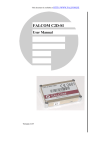
1
Jupiter 20
GPS receiver module
Data Sheet
Related documents
• Jupiter 20 Integrator’s manual LA000508
• Jupiter 20 Product brief LA000509
• Jupiter Series development kit guide
LA000645
• SiRF Binary protocol reference manual
• Navman NMEA reference manual
MN000315
• Jupiter 20 DR application note LA000433
• Low Power Operating Modes application
note LA000513
LA000507G © 2006 Navman New Zealand. All rights reserved. Proprietary information and specifications subject to change without notice.
Contents
1.0 Introduction........................................................................................................ 4
2.0 Technical description........................................................................................ 4
2.1 Product applications...................................................................................................... 4
2.2 Receiver architecture.................................................................................................... 4
2.3 Major components of the Jupiter 20.............................................................................. 5
2.4 Physical characteristics................................................................................................. 5
2.5 Mechanical specification............................................................................................... 5
2.6 External antenna surface mount pads.......................................................................... 5
2.7 I/O and power connections........................................................................................... 5
2.8 Environmental............................................................................................................... 6
2.9 Compliances................................................................................................................. 6
2.10 Marking/Serialisation................................................................................................... 6
3.0 Performance characteristics............................................................................ 6
3.1 TTFF (Time To First Fix)................................................................................................ 6
3.1.1 Hot start................................................................................................................. 6
3.1.2 Warm start............................................................................................................. 6
3.1.3 Cold start............................................................................................................... 6
3.2 Acquisition times........................................................................................................... 7
3.3 Timing 1PPS output...................................................................................................... 7
3.4 Battery backup (SRAM/RTC backup)........................................................................... 7
3.5 TricklePower mode........................................................................................................ 7
3.5.1 Adaptive TricklePower mode................................................................................. 7
3.5.2 Push‑To‑Fix mode................................................................................................. 7
3.6 Differential aiding.......................................................................................................... 8
3.6.1 Differential GPS (DGPS)....................................................................................... 8
3.6.2 Satellite Based Augmentation Systems (SBAS) including WAAS and EGNOS... 8
3.7 Navigation modes.......................................................................................................... 8
3.8 Core processor performance........................................................................................ 8
3.9 Sensitivity...................................................................................................................... 8
3.10 Dynamic constraints.................................................................................................... 9
3.11 Position and velocity accuracy..................................................................................... 9
4.0 Electrical requirements..................................................................................... 9
4.1 Power supply................................................................................................................. 9
4.1.1 Primary power........................................................................................................ 9
4.1.2 Low supply voltage detector.................................................................................. 9
4.1.3 VCC_RF power supply.......................................................................................... 9
4.1.4 External antenna voltage......................................................................................10
4.1.5 RF (Radio Frequency) input..................................................................................10
4.1.6 Antenna gain.........................................................................................................10
4.1.7 Burnout protection................................................................................................10
4.1.8 Jamming performance..........................................................................................10
4.1.9 Flash upgradability................................................................................................10
4.1.10 Reset input..........................................................................................................10
4.2 Data input output specifications ..................................................................................11
4.2.1 Voltage levels.......................................................................................................11
4.2.2 I/O surface mount pads.......................................................................................11
LA000507G © 2006 Navman New Zealand. All rights reserved. Proprietary information and specifications subject to change without notice.
5.0 Software interface........................................................................................... 13
5.1 NMEA output messages...............................................................................................13
5.2 SiRF binary..................................................................................................................13
5.3 Software functions and capabilities..............................................................................13
6.0 Dead Reckoning input specifications............................................................ 14
6.1 Gyro input specification................................................................................................14
6.2 Wheel tick rate.............................................................................................................14
6.3 Fwd/Rev input sense....................................................................................................14
7.0 Jupiter 20 development kit.............................................................................. 15
8.0 Jupiter 20 mechanical drawing...................................................................... 15
9.0 Product handling.............................................................................................. 16
9.1 Packaging and delivery................................................................................................16
9.2 Moisture sensitivity.......................................................................................................16
9.3 ESD sensitivity.............................................................................................................16
9.4 Safety...........................................................................................................................16
9.5 RoHS compliance........................................................................................................16
9.6 Disposal........................................................................................................................16
10.0 Ordering information..................................................................................... 17
11.0 Glossary and acronyms................................................................................. 17
Figures
Figure 2-1: Jupiter 20 module architecture.......................................................................... 4
Figure 8-1: Jupiter 20 mechanical layout............................................................................15
Tables
Table 3‑1: TTFF acquisition times....................................................................................... 7
Table 3‑2: Software processing performance..................................................................... 8
Table 3‑3: GPS receiver performance................................................................................ 8
Table 3‑4: Position and velocity accuracy........................................................................... 9
Table 4‑1: Operating power for the Jupiter 20..................................................................... 9
Table 4‑2: Typical jamming performance...........................................................................10
Table 4‑3: Interface voltage levels.....................................................................................11
Table 4‑4: J20D receiver pad functions.............................................................................11
Table 4‑5: J20/J20S receiver pad functions.......................................................................12
Table 5‑1: Jupiter 20 default baud rates.............................................................................13
Table 5‑2: Default NMEA messages..................................................................................13
Table 5‑3: Jupiter 20 software capability...........................................................................14
Table 6‑1: Gyro input specifications...................................................................................14
Table 10‑1: Jupiter 20 ordering information........................................................................17
LA000507G © 2006 Navman New Zealand. All rights reserved. Proprietary information and specifications subject to change without notice.
1.0 Introduction
The Jupiter 20 GPS receiver module is a very small surface mount receiver that is intended
as a component for OEM (Original Equipment Manufacturer) products. The module provides
a 12‑channel receiver that continuously tracks all satellites in view and provides accurate
positioning data.
2.0 Technical description
The highly integrated digital receiver incorporates and enhances the established technology
of the SiRFstarIIe/LP chipset. It is designed to meet the needs of the most demanding
applications, such as vehicle tracking in dense urban environments. The interface configuration
allows incorporation into many existing devices and legacy designs.
The Jupiter 20 receiver decodes and processes signals from all visible GPS satellites. These
satellites, in various orbits around the Earth, broadcast RF (radio frequency) ranging codes,
timing information, and navigation data messages. The receiver uses all available signals to
produce a highly accurate navigation solution. The 12‑channel architecture provides rapid TTFF
(Time To First Fix) under all start‑up conditions. Acquisition is guaranteed under all initialisation
conditions as long as visible satellites are not obscured.
The Jupiter 20 is available in three configurations:
• Jupiter 20 (standard) – GSW2.3 navigation software
• Jupiter 20S (high sensitivity) – with XTrac navigation software
• Jupiter 20D (Dead Reckoning) – with SiRFDRive software and gyro interface
Protocols supported are selected NMEA (National Marine Electronics Association) data
messages and SiRF binary.
2.1 Product applications
The module is designed for high performance and maximum flexibility in a wide range of OEM
configurations including hand‑helds, sensors, and in‑vehicle automotive products.
2.2 Receiver architecture
The functional architecture of the Jupiter 20 receiver is shown in Figure 2‑1.
Module architecture
DR Modules only
GYRO IN
forward/ wheel
reverse ticks
PWRIN
active or passive antenna
ADC
controls/ UART
ports
GPIO
TCXO
bias T
baseband
processor
LNA
bandpass
filter
RFIC
V_ANT
input
2.8 V
regulator
RFIN
RTC crystal
1.8 V
regulator
AD [0-18]
PWRIN
PWRIN
VBATT
ORing
circuit
D [0-15]
CTRL
Flash memory
brown out
detector
Figure 2-1: Jupiter 20 module architecture
LA000507G © 2006 Navman New Zealand. All rights reserved. Proprietary information and specifications subject to change without notice.
2.3 Major components of the Jupiter 20
LNA (Low Noise Amplifier): This amplifies the GPS signal and provides enough gain for the
receiver to use a passive antenna. A very low noise design is utilised to provide maximum
sensitivity.
Bandpass filter (1.575 GHz): This filters the GPS signal and removes unwanted signals caused by
external influences that would corrupt the operation of the receiver.
RFIC (Radio Frequency Integrated Circuit): The RFIC (SiRFstarII GRF 2i/LP) and related
components convert the GPS signal into an intermediate frequency and then digitise it for use by
the baseband processor.
TCXO (Temperature Compensated Crystal Oscillator): This highly stable 24.5535 MHz oscillator
controls the down conversion process for the RFIC block. Stability in this frequency is required
to achieve a fast TTFF.
Baseband processor: The SiRFstarII GSP 2e/LP processor is the main engine of the GPS
receiver. It runs all GPS signal measurement code, navigation code, and other ancillary routines,
such as power saving modes. The normal I/O of this processor is via the two serial ports.
Flash memory: The Flash memory stores software and also some long term data.
RTC (Real Time Clock) crystal: The 32 kHz crystal operates in conjunction with the RTC inside
the baseband processor. It provides an accurate clock function when main power has been
removed, if the battery backup is connected.
Reset generator: There are two voltage threshold reset generators in the Jupiter 20. The first
provides a reset to the baseband block if the main power drops below a low limit threshold.
The second shuts off the supply to the RTC in case the backup battery drops below a lower
threshold. This is used to compensate for a slow SiRF rise-time backup voltage.
Regulators: The regulators provide a clean and stable voltage supply to the components in the
receiver.
DR (Dead Reckoning) components: The Jupiter 20D has additional components allowing direct
connection to a turn rate gyro. The gyro input takes the form of a high resolution ADC (Analogue
to Digital Converter), where the analogue signal is digitised and prepared for use by the
SiRFDRive DR software running in the baseband processor.
2.4 Physical characteristics
The Jupiter 20 receiver is packaged on a miniature printed circuit board with a metallic RF
enclosure on one side. The standard or DR configuration must be selected at the time of
ordering and is not available for field retrofitting.
A lead‑free RoHS compliant product has been available since the end of 2005.
2.5 Mechanical specification
The physical dimensions of the Jupiter 20 are as follows:
length: 25.4 mm ± 0.1 mm
width: 25.4 mm ± 0.1 mm
thickness:3.0 mm max
weight: 4.0 g max
Refer to Figure 8‑1 for the Jupiter 20 mechanical drawing.
2.6 External antenna surface mount pads
The RF surface mount pad for the external antenna has a characteristic impedance of 50 ohms.
2.7 I/O and power connections
The I/O (Input Output) and power connections use surface mount pads with edge plating around
the edge of the module.
LA000507G © 2006 Navman New Zealand. All rights reserved. Proprietary information and specifications subject to change without notice.
2.8 Environmental
The environmental operating conditions of the Jupiter 20 are as follows:
temperature: –40ºC to +85ºC
humidity: up to 95% non‑condensing or a wet bulb temperature of +35ºC
altitude: –304 m to 18 000 m
vibration: random vibration IEC 68‑2‑64
max. vehicle dynamics:500 m/s
shock (non‑operating): 18 G peak, 5 ms
2.9 Compliances
The Jupiter 20 complies with the following:
• Directive 2002/95/EC on the restriction of the use of certain hazardous substances in
electrical and electronic equipment (RoHS)
• CISPR22 and FCC: Part 15, Class B for radiated emissions
• Automotive standard TS 16949
• Manufactured in an ISO 9000 : 2000 accredited facility
2.10 Marking/Serialisation
The Jupiter 20 supports a code 128 barcode indicating the unit serial number. The Navman
13‑character serial number convention is:
characters 1 and 2: year of manufacture (e.g. 06 = 2006, 07 = 2007)
characters 3 and 4: week of manufacture (1 to 52, starting first week in January)
character 5: manufacturer code
characters 6 and 7: product and type
character 8: product revision
characters 9-13: sequential serial number
3.0 Performance characteristics
3.1 TTFF (Time To First Fix)
TTFF is the actual time required by a GPS receiver to achieve a position solution. This
specification will vary with the operating state of the receiver, the length of time since the last
position fix, the location of the last fix, and the specific receiver design.
3.1.1 Hot start
A hot start results from a software reset after a period of continuous navigation, or a return
from a short idle period (i.e. a few minutes) that was preceded by a period of continuous
navigation. In this state, all of the critical data (position, velocity, time, and satellite
ephemeris) is valid to the specified accuracy and available in SRAM (Static Random Access
Memory). Battery backup of the SRAM and RTC during loss of power is required to achieve a
hot start.
3.1.2 Warm start
A warm start typically results from user‑supplied position and time initialisation data or
continuous RTC operation with an accurate last known position available in memory. In this
state, position and time data are present and valid but ephemeris data validity has expired.
3.1.3 Cold start
A cold start acquisition results when either position or time data is unknown. Almanac
information is used to identify previously healthy satellites.
LA000507G © 2006 Navman New Zealand. All rights reserved. Proprietary information and specifications subject to change without notice.
3.2 Acquisition times
Table 3‑1 shows the corresponding TTFF times for each of the acquisition modes.
J20
Mode
J20S
J20D
Typ
90%
Typ
90%
Typ
90%
TTFF hot
(valid almanac, position, time & ephemeris)
8 s
12 s
8 s
12 s
8 s
12 s
TTFF warm
(valid almanac, position & time)
38 s
42 s
38 s
40 s
35 s
40 s
TTFF cold
(valid almanac)
44 s
55 s
45 s
56 s
52 s
70 s
re‑acquisition
(<10 s obstruction with valid almanac,
position, time & ephemeris)
100 ms 100 ms 100 ms 100 ms 100 ms 100 ms
Table 3‑1: TTFF acquisition times
3.3 Timing 1PPS output
The 1PPS (Pulse Per Second) output of the Jupiter 20 receiver is < 1 µs, typical ± 300 ns in
reference to UTC (Coordinated Universal Time). This feature is currently only available on the
Jupiter 20 standard module.
3.4 Battery backup (SRAM/RTC backup)
During powered down conditions, the SRAM and RTC may be kept operating by supplying
power from the VBATT as shown in Table 4‑1. The Jupiter 20 can accept slow VBATT supply
rise time (unlike many other SiRFstarII based receivers) due to an on‑board voltage detector.
3.5 TricklePower mode
During normal mode of operation the Jupiter 20 is continuously running, providing a navigation
solution at the maximum rate of once per second. This continuous mode provides no power
saving.
The TricklePower mode of operation can be enabled to reduce the average power consumption.
The main power is supplied to the module continuously. An internal timer wakes the processor
from sleep mode. The module computes a navigation position fix, after which the processor
reverts to sleep mode. The duty cycle is controlled by a user‑configurable parameter.
If ephemeris data becomes outdated, the TricklePower mode will attempt to refresh the data set
within every 30-minute period, or for every new satellite that comes into view.
With TricklePower set to a 20% duty cycle, a power saving of 50% can easily be achieved with
minimal degradation in navigation performance.
3.5.1 Adaptive TricklePower mode
In Adaptive TricklePower mode, the processor automatically returns to full power when signal
levels are below the level at which they can be tracked in TricklePower mode. This is the
default behaviour when TricklePower is active.
3.5.2 Push‑To‑Fix mode
Unlike TricklePower, the operation in this mode is not cyclic. This mode always forces the
GPS software to revert to a continuous sleep mode after a navigation position fix. It will stay
in sleep mode until woken by activation of the reset input, and compute a fresh position.
If the ephemeris data becomes invalid, the RTC has the ability to self activate and refresh the
data, thus keeping the restart TTFF very short.
This mode yields the lowest power consumption of the module, and is ideal where a battery
powered application requires very few position fixes.
For further information on the TricklePower and Push‑To‑Fix modes refer to the Low Power
Operating Modes application note (LA000513).
LA000507G © 2006 Navman New Zealand. All rights reserved. Proprietary information and specifications subject to change without notice.
3.6 Differential aiding
3.6.1 Differential GPS (DGPS)
DGPS specification improves the Jupiter 20 horizontal position accuracy to <4 m 2 dRMS.
3.6.2 Satellite Based Augmentation Systems (SBAS) including WAAS and EGNOS
SBAS improves horizontal position accuracy by correcting GPS signal errors caused by
ionospheric disturbances, timing and satellite orbit errors. The Jupiter 20 is capable of
receiving WAAS and EGNOS differential corrections. Both SBAS and DGPS should improve
position accuracy. However, other factors can affect accuracy, such as GDOP (Geometric
Dilution of Precision), multipath, distance from DGPS reference station and latency of
corrections. Note also that XTrac does not support differential aiding.
3.7 Navigation modes
The Jupiter 20 GPS receiver supports 3D (three‑dimensional) and 2D (two‑dimensional) modes
of navigation.
3D navigation: The receiver defaults to 3D navigation when at least four GPS satellites are being
tracked. In 3D navigation, the receiver computes latitude, longitude, altitude, and time from
satellite measurements.
2D navigation: When less than four GPS satellite signals are available, or when a fixed altitude
value can be used to produce an acceptable navigation solution, the receiver will enter 2D
navigation mode using a fixed value of altitude determined by the host. Forced operation in 2D
mode can be commanded by the host.
In 2D navigation, the navigational accuracy is primarily determined by the relationship of the
fixed altitude value to the true altitude of the antenna. If the fixed value is correct, the specified
horizontal accuracies apply. Otherwise, the horizontal accuracies will degrade as a function of
the error in the fixed altitude.
3.8 Core processor performance
The standard Jupiter 20 with GSW2 software runs at a CPU clock speed of 12.28 MHz. Using
XTrac software (Jupiter 20S), the clock speed increases to 24.5 MHz. An SDK (Software
Development Kit) is available from SiRF to customise the Jupiter 20 firmware. Using the SiRF
SDK the clock speed can be increased up to 49 MHz.
The processing power used by the navigation software is shown in Table 3‑2.
Parameter
J20/J20D
J20S
typical performance
2‑3 MIPS
4‑5 MIPS
peak performance
6‑7 MIPS
8‑9 MIPS
Table 3‑2: Software processing performance
3.9 Sensitivity
The GPS receiver performance of the Jupiter 20 is shown in Table 3‑3.
Parameter
J20/J20D
J20S
acquisition sensitivity
–135 dBm
33 dBHz
–135 dBm
33 dBHz
navigation sensitivity
–141 dBm
28 dBHz
–152 dBm
17 dBHz
tracking sensitivity
–143 dBm
26 dBHz
–154 dBm
15 dBHz
Table 3‑3: GPS receiver performance
LA000507G © 2006 Navman New Zealand. All rights reserved. Proprietary information and specifications subject to change without notice.
3.10 Dynamic constraints
The Jupiter 20 receiver is programmed to deliberately lose track if any of the following limits are
exceeded:
Velocity: 500 m/s max
Acceleration: 4 G (39.2 m/s2) max
Vehicle jerk: 5 m/s3 max
Altitude: 18 000 m max (referenced to MSL)
3.11 Position and velocity accuracy
The position and velocity accuracy of the Jupiter 20 are shown in Table 3‑4, assuming full
accuracy C/A code (Clear/Acquisition). These values are the same in normal operation and
when TricklePower is active.
Parameter
J20/J20D
J20S
horizontal CEP
2.1 m
2.2 m
horizontal (2 dRMS)
5.2 m
5.5 m
vertical VEP
2.5 m
2.5 m
velocity 2D (2 sigma)*
0.1 m/s
0.15 m/s
*at a velocity greater than 5 km/h
Table 3‑4: Position and velocity accuracy
4.0 Electrical requirements
4.1 Power supply
4.1.1 Primary power
The Jupiter 20 GPS receiver is designed to operate from a single supply voltage, meeting the
requirements shown in Table 4‑1.
Parameter
input voltage
current (typ) at full power (3.3 V)
current (max)
current (typ) at 20% TricklePower
TM
J20
J20S
J20D
2.9 to 3.6 VDC
2.9 to 3.6 VDC
2.9 to 3.6 VDC
75 mA
85 mA
80 mA
100 mA
100 mA
100 mA
35 mA
60 mA
35 mA
battery backup voltage
2.4 V to 3.6 V
battery backup current
<10 µA typ at 25°C
maximum rise time
ripple
unlimited
not to exceed 50 mV peak to peak
Table 4‑1: Operating power for the Jupiter 20
4.1.2 Low supply voltage detector
The module will enter a reset mode if the main supply drops below 2.8 V.
4.1.3 VCC_RF power supply
The VCC_RF (pad 20) provides a regulated 2.8 V power source. The specifications for this
supply are as follows:
voltage: 2.8 V ± 2%
current max: 25 mA for J20/J20S; 5 mA for J20D
LA000507G © 2006 Navman New Zealand. All rights reserved. Proprietary information and specifications subject to change without notice.
4.1.4 External antenna voltage
DC power is supplied to the external antenna through the antenna power input pad (VANT).
The receiver does not use this supply. The DC supply to the RF connection does not current
limit in the event of a short circuit. Reference designs for antenna current limit are available in
the Jupiter 20 Integrator’s manual (LA000508).
The external antenna characteristics are as follows:
voltage (typ): 3.3 V
voltage max: 12 V
current max: 100 mA
Warning: if the antenna or its cable develops a short circuit and the external antenna
current is not limited, the GPS receiver will experience permanent damage.
4.1.5 RF (Radio Frequency) input
RF input is 1575.42 MHz (L1 Band) at a level between –135 dBm and –152 dBm into a 50 ohm
impedance. This input may have a DC voltage impressed upon it to supply power to an active
antenna. The maximum input return loss is –9 dB.
4.1.6 Antenna gain
The receiver will operate with a passive antenna of unity gain. However, GPS performance
will be optimum when an active antenna is used. The gain of this antenna should be in the
range of 20 dB to 30 dB.
4.1.7 Burnout protection
The receiver accepts without risk of damage a signal of +10 dBm from 0 to 2 GHz carrier
frequency, except in band 1560 to 1590 MHz where the maximum level will be –10 dBm.
4.1.8 Jamming performance
The typical jamming performance of the receiver based upon a 3 dB degradation in C/N0
(Carrier to Noise power ratio) performance is shown in Table 4‑2. This is with reference to the
external antenna.
Frequency MHz
Jamming signal
power dBm
1400
–19
1425.42
–16
1530
–27
1555
–69
1575.42
–114
1625.42
–33
1725.42
–19
Table 4‑2: Typical jamming performance
4.1.9 Flash upgradability
The firmware programmed in the Flash memory may be upgraded via the serial port. The
user can control this by pulling the Serial BOOT pad (3) high at startup, then downloading the
code from a PC with suitable software (e.g. SiRFFlash). In normal operation this pad should
be left floating for minimal current drain. It is recommended that in the user’s application, the
BOOT pad is connected to a test pad for use in future software upgrades.
4.1.10 Reset input
This active low input (pad 22) allows the user to restart the software from an external signal.
It is also used to initiate a ‘push‑to‑fix’ navigation cycle. In normal operation this pad should
be left floating or activated by an open drain driver. Active pull‑up is not recommended.
LA000507G © 2006 Navman New Zealand. All rights reserved. Proprietary information and specifications subject to change without notice.
10
4.2 Data input output specifications
All communications between the Jupiter 20 receiver and external devices are through the I/O
surface mount pads. These provide the contacts for power, ground, serial I/O and control. Power
requirements are discussed in Section 4.1.
4.2.1 Voltage levels
The I/O connector voltage levels measured at PWR_IN = 3 V are shown in Table 4‑3.
Signal
Parameter
Value
VIH (min)
2.0 V
VIH (max)
PWR_IN +0.1 V
VIL (min)
0.1 V
VIL (max)
0.8 V
VOH (min) at IOH 2 mA
2.0 V
VOH (max)
PWR_IN
VOL (min)
0
VOL (max) at IOL –2 mA
1.0 V
max capacitance Cmax
100 pF
input current max
–600 μA
pulse time min
200 μs
TXD & RXD
GPIOs
SPI bus
Reset input*
*Reset input should not be driven high by external circuits. It
is recommended that this input is driven low by an open drain
interface.
Table 4‑3: Interface voltage levels
4.2.2 I/O surface mount pads
Details of the surface mount pad functions are shown in Table 4‑4 and 4-5.
Pad
No.
Name
Type
8*
GYRO_IN
I
gyro input (analogue 0–5 V)
27*
FWD/REV
I
fwd/rev input (low=forward, high=reverse)
28*
WHEEL_TICKS
I
wheel tick input
Description
* See also Table 4‑5 for J20/J20S pad functions
Table 4‑4: J20D receiver pad functions
LA000507G © 2006 Navman New Zealand. All rights reserved. Proprietary information and specifications subject to change without notice.
11
Pad
No.
Name
Type
1
PWRIN
P
main power input (3.3 V)
2
GND
P
ground
3
BOOT
I
serial boot (high for serial boot, low or open circuit for
normal operation)
4
RXA
I
CMOS level asynchronous input for UART A
5
TXA
O
CMOS level asynchronous output for UART A
6
TXB
O
CMOS level asynchronous output for UART B
7
RXB
I
CMOS level asynchronous input for UART B
8*
GPIO3/
ADC_CONV/
NANT_SC
IO
general purpose IO/
output for external A/D converter control/
antenna short circuit sensor input (active low)
9
RF_ON
O
output to indicate whether the RF section is enabled
(active high)
10
GND
P
ground
11
GND
P
ground
12
GND
P
ground
13
GND
P
ground
14
GND
P
ground
15
GND
P
ground
16
GND
P
ground
17
RF_IN
I
antenna signal input
18
GND
P
ground
19
V_ANT
P
external power supply for active antenna
20
VCC_RF
O
RF Power (+2.8 V) supply output
21
V_BATT
P
backup battery input
22
RESET
I
master reset (active low)
23
GPIO10/GPS_FIX
IO
general purpose IO or GPS fix indication (active low)
24
GPIO6/SDO
IO
general purpose IO or SPI serial data out
25
GPIO5/SDI
IO
general purpose IO or SPI serial data in
26
GPIO7/SCK
IO
general purpose IO or SPI serial clock
27*
GPIO15/
ANT_OC
IO
general purpose IO/
antenna open circuit sensor input (active high)
28*
GPIO1/
ANT_CTRL
IO
general purpose IO/
antenna DC power control output (ON=high)
29
GPIO9/1PPS
O
general purpose IO or 1 pulse per second output
30
GND
P
ground
Description
* See also Table 4‑4 for J20D pad functions
Table 4‑5: J20/J20S receiver pad functions
LA000507G © 2006 Navman New Zealand. All rights reserved. Proprietary information and specifications subject to change without notice.
12
5.0 Software interface
The host serial I/O port of the receiver’s serial data interface supports full duplex communication
between the receiver and the user. The default serial modes are shown in Table 5‑1.
Port
J20
(GSW2.3)
J20S
(XTrac)
J20D
(SiRFDRive 1.0)
Port A
NMEA, 9600
NMEA, 9600
NMEA, 9600
Port B
RTCM, 9600
SiRF binary, 38 400
RTCM, 9600
Table 5‑1: Jupiter 20 default baud rates
5.1 NMEA output messages
The output NMEA (0183 v2.2) messages and intervals for the receiver are listed in Table 5‑2.
A complete description of each NMEA message is contained in the Navman NMEA reference
manual (MN000315).
NMEA message
J20
J20S
J20D
GGA
1 s
1 s
1 s
GSA
1 s
1 s
1 s
GSV
1 s
1 s
1 s
RMC
1 s
1 s
1 s
VTG
1 s
1 s
1 s
GLL
1 s
1 s
1 s
ZDA
1 s
N/A
N/A
PTTK, DR
N/A
N/A
1 s
N/A=not available
Table 5‑2: Default NMEA messages
5.2 SiRF binary
A complete description of each binary message is contained in the SiRF Binary Protocol
reference manual.
5.3 Software functions and capabilities
The Jupiter 20 has additional capabilities to the standard SiRF GPS software:
• GPS fix output – GPIO10 Low for 2D or 3D fix
• GPIO command control via serial commands – for use by customer
• Gyro, wheel‑tick and forward reverse inputs (DR only)
• Antenna power monitor messages and power control O/P (non DR only)
• PTTK, DR – DR status messages in NMEA protocol format
Refer to the Jupiter 20 Integrator’s manual (LA000508) for further information.
LA000507G © 2006 Navman New Zealand. All rights reserved. Proprietary information and specifications subject to change without notice.
13
Table 5‑3 shows the software features available with the Jupiter 20 configurations.
Feature
Description
J20
GSW2.3
J20S
XTrac
J20D
SiRFDrive
SBAS capability
Improves position accuracy by using freely available
satellite‑based correction services called SBAS (Satellite
Based Augmentation System)
A
A
DGPS ready
Accepts DGPS corrections in the RTCM SC‑104 format
E
E
TricklePower
Improves battery life using this enhanced power management
mode
A
A
Intelligently switches between TricklePower and full power
depending on the current GPS signal level (when TricklePower
is enabled)
E
yes
Adaptive
TricklePower
Advanced power Improves battery life using a software‑based power
management
management
A
Push‑to‑Fix
Provides an on‑demand position fix mode designed to further
improve battery life
Almanac to
Flash
Improves cold start times by storing the most recent almanac to
flash memory
Low signal
acquisition
Acquires satellites and continues tracking in extremely low
signal environments
Low signal
navigation
Continues navigating in extremely low signal environments
1 PPS
A timing signal generated every second on the second
yes=always enabled
A = available
A
A
yes
yes
yes
yes
E
E
E = enabled by default in production units
Table 5‑3: Jupiter 20 software capability
6.0 Dead Reckoning input specifications
6.1 Gyro input specification
The specifications shown in Table 6‑1 apply to the Jupiter 20D only.
Characteristics
Value
Unit
input max voltage range
max +5, min 0
VDC
input resistance nominal
18.2
kΩ
nominal bias at zero angular velocity
2.5
VDC
nominal scale factor
22.2
mV per degrees/s
± 0.5 max
%
0.055
degrees/s
± 80
degrees/s
linearity
angular resolution
max gyro angular rate
Note that clockwise rotation should cause the input to rise
Table 6‑1: Gyro input specifications
At the time of publication, recommended manufacturers of gyros are as follows:
Murata ENV series
Panasonic EWTS series
(Navman takes no responsibility for the use of these gyros in an application.)
6.2 Wheel tick rate
The wheel tick rate is 4 kHz maximum, 1 Hz minimum.
6.3 Fwd/Rev input sense
The fwd/rev input sense is: LOW=forward, HIGH=reverse. External pull down is required if this
input is not used.
LA000507G © 2006 Navman New Zealand. All rights reserved. Proprietary information and specifications subject to change without notice.
14
7.0 Jupiter 20 development kit
The Jupiter 20 Development kit series assists in the integration of the Jupiter 20 module
in custom applications. The Development kit contains all of the necessary hardware and
software to carry out a thorough evaluation of the Jupiter 20 module. Refer to the Jupiter Series
Development kit guide (LA000645) for further details.
The following development kits are available for Jupiter 20 products:
• TU10-D057-400 Jupiter 20 Development kit RoHS
• TU10-D057-401 Jupiter 20 S Development kit RoHS
• TU10-D057-402 Jupiter 20 DR Development kit RoHS
8.0 Jupiter 20 mechanical drawing
25.4 ± 0.1
30
15
16
25.4 ± 0.1
1
top view
3.0 max
1.277
0.8
2.8
1.9
side view
3.0 max
R0.4
side view
A
1.5
1.0
23.4
detail A
scale 6:1
bottom view
all dimensions are in mm
Figure 8-1: Jupiter 20 mechanical layout
LA000507G © 2006 Navman New Zealand. All rights reserved. Proprietary information and specifications subject to change without notice.
15
9.0 Product handling
9.1 Packaging and delivery
Jupiter 20 modules are shipped in Tape and Reel form. The reeled modules are shipped with
250 units per 300 x 44 mm (D x W) reel with a pitch of 32 mm. Each reel is ‘dry’ packaged and
vacuum sealed in an MMB (Moisture Barrier Bag) with two silica gel packs and placed in a
carton.
The MOQ (Minimum Order Quantity) for shipping is 250 units.
All packaging is ESD protective lined. Please follow the MSD and ESD handling instructions on
the labels of the MMB and exterior carton (refer to sections 9.2 and 9.3).
9.2 Moisture sensitivity
The Jupiter 20 GPS receiver is an MSD (Moisture Sensitive Device). Precautionary measures
are required in handling, storing and using such devices to avoid damage from moisture
absorption. If localised heating is required to rework or repair the device, precautionary methods
are required to avoid exposure to solder reflow temperatures that can result in performance
degradation.
Further information can be obtained from the IPC/JEDEC standard J‑STD‑033: Handling,
Packing, Shipping and Use of Moisture/Reflow Sensitive Surface Mount Devices.
9.3 ESD sensitivity
The Jupiter 20 GPS receiver contains class 1 devices and is ESDS (ElectroStatic Discharge
Sensitive). Navman recommends the two basic principles of protecting ESDS devices from
damage:
• Only handle sensitive components in an ESD Protected Area (EPA) under protected and
controlled conditions
• Protect sensitive devices outside the EPA using ESD protective packaging
All personnel handling ESDS devices have the responsibility to be aware of the ESD threat to
reliability of electronic products.
Further information can be obtained from the IEC Technical Report IEC61340‑5‑1 & 2:
Protection of electronic devices from electrostatic phenomena.
9.4 Safety
Improper handling and use of the Jupiter GPS receiver can cause permanent damage to the
receiver and may even result in personal injury.
9.5 RoHS compliance
This product complies with Directive 2002/95/EC on the restriction of the use of certain
hazardous substances in electrical and electronic equipment.
9.6 Disposal
We recommend that this product should not be treated as household waste. For
more detailed information about recycling of this product, please contact your local
waste management authority or the reseller from who you purchased the product.
LA000507G © 2006 Navman New Zealand. All rights reserved. Proprietary information and specifications subject to change without notice.
16
10.0 Ordering information
The part numbers of the Jupiter 20 variants are shown in Table 10‑1.
Part Number
Description
TU20‑D411‑001
Jupiter 20 (standard)
TU20‑D411‑101
Jupiter 20S (with XTrac)
TU20‑D421‑201
Jupiter 20D (with Dead Reckoning)
TU20‑D101‑001
Jupiter 20 std adapter
TU10‑D007‑400
Jupiter 20 std development kit
TU10‑D007‑401
Jupiter 20S development kit
TU10‑D007‑402
Jupiter 20D development kit
Table 10‑1: Jupiter 20 ordering information
11.0 Glossary and acronyms
2dRMS: twice distance Root Mean Square
ADC: Analogue to Digital Converter
Almanac: A set of orbital parameters that allows calculation of approximate GPS satellite
positions and velocities. The almanac is used by a GPS receiver to determine satellite visibility
and as an aid during acquisition of GPS satellite signals. The almanac is a subset of satellite
ephemeris data and is updated weekly by GPS Control.
C/A code: Coarse Acquisition code
A spread spectrum direct sequence code that is used primarily by commercial GPS receivers to
determine the range to the transmitting GPS satellite.
DGPS: Differential GPS
A technique to improve GPS accuracy that uses pseudo‑range errors recorded at a known
location to improve the measurements made by other GPS receivers within the same general
geographic area.
GDOP: Geometric Dilution of Precision
A factor used to describe the effect of the satellite geometry on the position and time accuracy
of the GPS receiver solution. The lower the value of the GDOP parameter, the less the error in
the position solution. Related indicators include PDOP, HDOP, TDOP and VDOP.
EGNOS: European Geostationary Navigation Overlay Service
The system of geostationary satellites and ground stations developed in Europe to improve the
position and time calculation performed by the GPS receiver.
Ephemeris
A set of satellite orbital parameters that is used by a GPS receiver to calculate precise GPS
satellite positions and velocities. The ephemeris is used to determine the navigation solution and
is updated frequently to maintain the accuracy of GPS receivers.
GPS: Global Positioning System
A space‑based radio positioning system that provides accurate position, velocity, and time data.
OEM: Original Equipment Manufacturer
Re‑acquisition
The time taken for a position to be obtained after all satellites have been made invisible to the
receiver.
SBAS: Satellite Based Augmentation System
Any system using a network of geostationary satellites and ground stations to improve the
performance of a Global Navigation Satellite System (GNSS), e.g. EGNOS and WAAS.
SRAM: Static Random Access Memory
WAAS: Wide Area Augmentation System
System of satellites and ground stations developed by the FAA (Federal Aviation Administration)
providing GPS signal corrections. (Currently available for North America only.)
LA000507G © 2006 Navman New Zealand. All rights reserved. Proprietary information and specifications subject to change without notice.
17
SiRF and SiRF logo are registered trademarks of SiRF Technology, Inc. SiRFstar, Push-to-Fix, and TricklePower are
trademarks of SiRF Technology, Inc. All other trademarks mentioned in this document are property of their respective
owners.
© 2006 Navman New Zealand. All Rights Reserved.
Information in this document is provided in connection with Navman New Zealand (‘Navman’) products. These materials
are provided by Navman as a service to its customers and may be used for informational purposes only. Navman
assumes no responsibility for errors or omissions in these materials. Navman may make changes to specifications and
product descriptions at any time, without notice. Navman makes no commitment to update the information and shall have
no responsibility whatsoever for conflicts or incompatibilities arising from future changes to its specifications and product
descriptions. No license, express or implied, by estoppel or otherwise, to any intellectual property rights is granted by
this document. Except as provided in Navman’s Terms and Conditions of Sale for such products, Navman assumes no
liability whatsoever.
THESE MATERIALS ARE PROVIDED ‘AS IS’ WITHOUT WARRANTY OF ANY KIND, EITHER EXPRESSED OR
IMPLIED, RELATING TO SALE AND/OR USE OF NAVMAN PRODUCTS INCLUDING LIABILITY OR WARRANTIES
RELATING TO FITNESS FOR A PARTICULAR PURPOSE, CONSEQUENTIAL OR INCIDENTAL DAMAGES,
MERCHANTABILITY, OR INFRINGEMENT OF ANY PATENT, COPYRIGHT OR OTHER INTELLECTUAL PROPERTY
RIGHT. NAVMAN FURTHER DOES NOT WARRANT THE ACCURACY OR COMPLETENESS OF THE INFORMATION,
TEXT, GRAPHICS OR OTHER ITEMS CONTAINED WITHIN THESE MATERIALS. NAVMAN SHALL NOT BE
LIABLE FOR ANY SPECIAL, INDIRECT, INCIDENTAL, OR CONSEQUENTIAL DAMAGES, INCLUDING WITHOUT
LIMITATION, LOST REVENUES OR LOST PROFITS, WHICH MAY RESULT FROM THE USE OF THESE MATERIALS.
Navman products are not intended for use in medical, lifesaving or life sustaining applications. Navman customers using
or selling Navman products for use in such applications do so at their own risk and agree to fully indemnify Navman
for any damages resulting from such improper use or sale. Product names or services listed in this publication are for
identification purposes only, and may be trademarks of third parties. Third-party brands and names are the property
of their respective owners. Additional information, posted at www.navman.com, is incorporated by reference. Reader
response: Navman strives to produce quality documentation and welcomes your feedback. Please send comments
and suggestions to [email protected]. For technical questions, contact your local Navman sales office or field
applications engineer.
LA000507G © 2006 Navman New Zealand. All rights reserved. Proprietary information and specifications subject to change without notice.
18