1
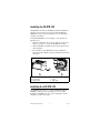
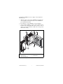
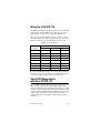
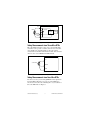
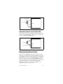
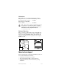
FieldPoint Operating Instructions
FP-RTD-122 and
cFP-RTD-122
Eight-Channel Three-Wire RTD and
Resistance Input Modules
These operating instructions describe how to install and use the
National Instruments FP-RTD-122 and cFP-RTD-122 three-wire
RTD and resistance input modules (referred to inclusively as the
[c]FP-RTD-122). For details on configuring and accessing the
[c]FP-RTD-122 over a network, refer to the user manual for the
FieldPoint network module you are using.
Features
The [c]FP-RTD-122 is a FieldPoint RTD and resistance input
module with the following features:
•
Inputs for 100 and 1,000 Ω platinum RTDs (resistance
temperature detectors)
•
Built-in linearization for six TCR (temperature coefficient of
resistance, or alpha) values of RTDs
•
Direct resistance measurements in 400 and 4,000 Ω ranges
•
True three-wire compensation
•
16-bit resolution
•
Filtering against 50 and 60 Hz noise
•
Hot swappable
•
2,300 Vrms transient overvoltage protection
•
–40 to 70 °C operation
FieldPoint™, National Instruments™, NI™, and ni.com™ are trademarks of National Instruments Corporation.
Product and company names mentioned herein are trademarks or trade names of their respective companies.
For patents covering National Instruments products, refer to the appropriate location: Help»Patents in your software,
the patents.txt file on your CD, or ni.com/patents.
323348B-01
April 2003
© 2002–2003 National Instruments Corp. All rights reserved.
Installing the FP-RTD-122
The FP-RTD-122 mounts on a FieldPoint terminal base (FP-TB-x),
which provides operating power to the module. Installing the
FP-RTD-122 onto a powered terminal base does not disrupt the
operation of the bank.
To install the FP-RTD-122, refer to Figure 1 and complete the
following steps:
1. Slide the terminal base key to either position X, used for any
module, or position 1, used for the FP-RTD-122 module.
2. Align the FP-RTD-122 alignment slots with the guide rails on
the terminal base.
3. Press firmly to seat the FP-RTD-122 on the terminal base.
When the module is firmly seated, the terminal base latch locks
it into place.
4
5
3
6
1
2
1 I/O Module
2 Terminal Base
3 Alignment Slot
4 Key
5 Latch
6 Guide Rails
Figure 1. Installing the FP-RTD-122
Installing the cFP-RTD-122
The cFP-RTD-122 mounts on a Compact FieldPoint backplane
(cFP-BP-x), which provides operating power to the module.
Installing the cFP-RTD-122 onto a powered backplane does not
disrupt the operation of the bank.
FP-RTD-122 and cFP-RTD-122
2
ni.com
To install the cFP-RTD-122, refer to Figure 2 and complete the
following steps:
1. Align the captive screws on the cFP-RTD-122 with the holes
on the backplane. The alignment keys on the cFP-RTD-122
prevent backward insertion.
2. Press firmly to seat the cFP-RTD-122 on the backplane.
3. Using a number 2 Phillips screwdriver with a shank of at least
64 mm (2.5 in.) length, tighten the captive screws to 1.1 N ⋅ m
(10 lb ⋅ in.) of torque. The nylon coating on the screws prevents
them from loosening.
4
3
5
2
4
2
1
1 cFP-RTD-122
2 Captive Screws
3 cFP Controller Module
4 Screw Holes
5 cFP Backplane
Figure 2. Installing the cFP-RTD-122
© National Instruments Corp.
3
FP-RTD-122 and cFP-RTD-122
Wiring the [c]FP-RTD-122
The FP-TB-x terminal bases have connections for each of the eight
input channels on the FP-RTD-122. The cFP-CB-x connector
blocks provide the same connections for the cFP-RTD-122.
Table 1 lists the terminal assignments for the signals associated
with each channel. The terminal assignments are the same for the
FP-TB-x terminal bases and the cFP-CB-x connector blocks.
Table 1. Terminal Assignments
Terminal Numbers
Channel
EX+
SENSE
COM
0
1
2
18
1
3
4
20
2
5
6
22
3
7
8
24
4
9
10
26
5
11
12
28
6
13
14
30
7
15
16
32
If you are using shielded wiring, you can reduce input signal noise
by connecting one end of the shield to the COM terminal. Do not
connect the shield to any of the wires at the signal end.
Taking RTD Measurements
with the [c]FP-RTD-122
The [c]FP-RTD-122 has eight input channels. All eight channels
share a common ground reference that is isolated from other
modules in the FieldPoint system. Each channel pulses a 0.25 mA
excitation current out of the EX+ terminal. The excitation current
returns through the COM terminal. The SENSE terminal measures
resistance and compensates for lead resistance errors. Each
channel is filtered, then sampled by a 16-bit analog-to-digital
converter.
FP-RTD-122 and cFP-RTD-122
4
ni.com
EX+
RTD
Pulsed
Input
Circuitry
16-bit
ADC
SENSE
COM
[c]FP-RTD-122
Figure 3. [c]FP-RTD-122 Input Circuitry
Taking Measurements from Three-Wire RTDs
Three-wire RTDs often have a wire of one color (usually white,
sometimes red) for positive excitation, and two wires of another
color (usually red, sometimes black). Connect the positive
excitation wire to the EX+ terminal of the module, and connect the
other two wires to the SENSE and COM terminals.
EX+
3-wire RTD
SENSE
COM
[c]FP-RTD-122
Figure 4. Three-Wire RTD Connections on One Channel
Taking Measurements from Four-Wire RTDs
For the best accuracy, use the NI [c]FP-RTD-124 for input from
four-wire RTDs. Otherwise, leave any one of the RTD wires
unconnected and connect the remaining three as you would for a
three-wire RTD. Refer to Figure 5.
© National Instruments Corp.
5
FP-RTD-122 and cFP-RTD-122
Leave this wire
unconnected
EX+
4-wire RTD
SENSE
COM
[c]FP-RTD-122
Figure 5. Four-Wire RTD Connections on One Channel
Taking Measurements from Two-Wire RTDs
Connect either wire of a two-wire RTD to the EX+ terminal and the
other wire to the COM terminal, and connect a short jumper wire
between the COM and SENSE terminals.
EX+
2-wire RTD
SENSE
Short Jumper Wire
COM
[c]FP-RTD-122
Figure 6. Two-Wire RTD Connections on One Channel
Measuring Resistance Directly
You can use the [c]FP-RTD-122 to measure resistance in ohms.
In this way, you can take measurements from RTDs of types that
the [c]FP-RTD-122 does not directly support (such as 120 Ω nickel
RTDs) and from resistive devices other than RTDs. You can choose
one of two resistance ranges: 0–400 and 0–4,000 Ω. Resistance
values outside the range you select, including open circuits, result
in an Out of range error for the affected channels. The
[c]FP-RTD-122 ignores any configuration of RTD type for
channels with resistance ranges selected.
FP-RTD-122 and cFP-RTD-122
6
ni.com
Converting Resistance Measurements
to Temperature Measurements
The [c]FP-RTD-122 has built-in linearization algorithms for
platinum RTDs of either 100 or 1,000 Ω nominal resistance,
and for six TCR (or alpha, α) values. The TCR is the average
temperature coefficient of resistance of an RTD from 0 to 100 °C.
This document specifies TCR in units of mΩ/Ω/°C.
The [c]FP-RTD-122 linearizes resistance values and returns
readings in units of temperature. The available ranges are
73 to 1,123 K, –200 to 850 °C, and –328 to 1,562 °F. You can
configure each channel independently, so you can connect different
types of RTDs to each channel.
You must configure each channel of the
[c]FP-RTD-122 for the RTD type connected to it. The
module does not automatically recognize RTD types.
Note
RTD Types
RTD types are specified by material composition, nominal
resistance at 0 °C, and TCR. The [c]FP-RTD-122 can directly
measure the temperature of platinum RTDs of either 100 or
1,000 Ω nominal resistance. These RTDs are commonly referred to
as PT100 or PT1000 RTDs, respectively.
Different types of platinum RTDs have different TCRs. The
[c]FP-RTD-122 supports the following TCRs: 3.750, 3.851, 3.911,
3.916, 3.920, and 3.928 mΩ/Ω/°C. The most common TCR for
RTDs is 3.851 mΩ/Ω/°C. It is defined in international standards
such as IEC-751, DIN 43760, BS 1904, and ASTM E1137.
The TCR of 3.928 mΩ/Ω/°C is used in the reference function for
platinum thermometers in the International Temperature Scale
of 1990 (ITS-90) for high-accuracy metrology applications.
Unfortunately, not all TCR values are as well defined by standards
organizations, and the behavior of RTDs with the same TCR value
may vary from vendor to vendor. The variations are usually small,
and the built-in linearization algorithms of the [c]FP-RTD-122 are
appropriate for nearly all applications.
© National Instruments Corp.
7
FP-RTD-122 and cFP-RTD-122
The [c]FP-RTD-122 uses a linearization curve known as the
Callendar-Van Dusen equation to measure the temperature of
RTDs. The equation is as follows:
Temperatures below 0 °C:
RT = R0 [1 + A × T + B × T 2 + C × T 3 × (T – 100 °C)]
Temperatures above 0 °C:
RT = R0[1 + A × T + B × T 2]
T = temperature in °C
RT = RTD resistance at temperature T
R0 = RTD nominal resistance at 0 °C
A, B, C are coefficients given in Table 2.
Table 2 lists the coefficients used in this equation for each of the
TCR values that the [c]FP-RTD-122 supports. If you have a
nonstandard RTD that does not match one of these linearization
curves, measure the resistance with the [c]FP-RTD-122 and
convert the resistance to temperature in the manner suggested by
the RTD vendor.
Table 2. Callendar-Van Dusen Coefficients Used by the [c]FP-RTD-122
TCR
mΩ/Ω/°C
A
(°C)–1
B
(°C)–2
C
(°C)–4
3.750a
3.81 × 10⁻³
–6.02 × 10⁻⁷
–6.0 × 10⁻¹²
3.851b
3.9083 × 10⁻³
–5.775 × 10⁻⁷
–4.183 × 10⁻¹²
3.911c
3.9692 × 10⁻³
–5.8495 × 10⁻⁷
–4.233 × 10⁻¹²
3.916d
3.9739 ×
–5.870 ×
3.920e
3.9787 × 10⁻³
–5.8686 × 10⁻⁷
–4.167 × 10⁻¹²
3.928f
3.9888 × 10⁻³
–5.915 × 10⁻⁷
–3.85 × 10⁻¹²
10–3
10–7
–4.4 × 10⁻¹²
Three-Wire Compensation of Lead
Resistance Errors
The [c]FP-RTD-122 uses a three-wire compensation technique to
compensate for the lead resistances. The SENSE lead measures the
resistance of the return COM lead. If the EX+ lead has the same
resistance as the COM lead, the [c]FP-RTD-122 corrects for the
FP-RTD-122 and cFP-RTD-122
8
ni.com
effects of the leads. The only residual errors are those caused by
mismatching the EX+ and COM leads. Most RTDs have lead
resistances within 5% of each other, so the compensation of the
[c]FP-RTD-122 corrects for 95% or more of the errors introduced
by lead resistances. This is a more accurate method than the typical
bridge completion methods described in many reference books.
The bridge methods not only have the same sensitivity to lead
resistance mismatch, but also are effective only for temperatures
very near those at which the bridge is balanced (usually 0 °C).
The temperature measurement accuracy specifications for the
[c]FP-RTD-122 at the end of these instructions include the effects
of a typical application using 10 m of 22 gauge copper wire
(approximately 0.5 Ω per lead), with 5% mismatch in the lead
resistances. If you are using leads with greater resistances, the
additional errors are approximately 3 °C per Ω of mismatch in the
lead resistances for 100 Ω RTDs, and 0.3 °C per Ω of mismatch in
the lead resistance for 1,000 Ω RTDs. For example, for 2 Ω leads
matched to 5% of each other, the lead resistance mismatch is
5% × 2 Ω = 0.1 Ω, which would cause 0.3 °C of error in
measurements of a 100 Ω RTD.
If you are using the [c]FP-RTD-122 with two-wire RTDs, the
errors due to lead resistances are much greater because three-wire
compensation is not used. With two-wire RTDs, the additional
errors are approximately 3 °C per Ω of the sum of the lead
resistances for 100 Ω RTDs, and 0.3 °C per Ω of the sum of lead
resistances for 1,000 Ω RTDs. For example, a 1,000 Ω two-wire
RTD with 2 Ω leads has a total lead resistance of 4 Ω (2 Ω per lead),
which causes 1.2 °C of error.
Status Indicators
The [c]FP-RTD-122 has two green status LEDs, POWER and
READY. After you insert the [c]FP-RTD-122 into a terminal base
or backplane and apply power to the connected network module,
the green POWER indicator lights and the [c]FP-RTD-122
informs the network module of its presence. When the network
module recognizes the [c]FP-RTD-122, it sends initial
configuration information to the [c]FP-RTD-122. After the
[c]FP-AI-111 receives this initial information, the green READY
indicator lights and the module is in normal operating mode.
© National Instruments Corp.
9
FP-RTD-122 and cFP-RTD-122
Upgrading the FieldPoint Firmware
You may need to upgrade the FieldPoint firmware when you add
new I/O modules to the FieldPoint system. For information on
determining which firmware you need and how to upgrade your
firmware, go to ni.com/info and enter fpmatrix.
Isolation and Safety Guidelines
Read the following information before
attempting to connect the [c]FP-RTD-122 to any circuits
that may contain hazardous voltages.
Caution
This section describes the isolation of the [c]FP-RTD-122 and its
compliance with international safety standards. The field wiring
connections are isolated from the backplane and the inter-module
communication bus. The isolation is provided by the module,
which has optical and galvanic isolation barriers designed and
tested to protect against transient fault voltages of up to 2,300 Vrms.
Follow these guidelines to ensure a safe total system:
•
The [c]FP-RTD-122 has a safety isolation barrier between the
I/O channels and the inter-module communication bus. There
is no isolation between channels unless otherwise noted. If any
of the channels on a module are wired at a hazardous potential,
make sure that all other devices or circuits connected to that
module are properly insulated from human contact.
•
Do not share the external supply voltages (the V and C
terminals) with other devices (including other FieldPoint
devices), unless those devices are isolated from human contact.
•
For Compact FieldPoint, you must connect the protective earth
(PE) ground terminal on the cFP-BP-x backplane to the system
safety ground. The backplane PE ground terminal has the
following symbol stamped beside it: . Connect the
backplane PE ground terminal to the system safety ground
using 14 AWG (1.6 mm) wire with a ring lug. Use the 5/16 in.
panhead screw shipped with the backplane to secure the ring
lug to the backplane PE ground terminal.
•
As with any hazardous voltage wiring, make sure that all
wiring and connections meet applicable electrical codes and
commonsense practices. Mount terminal bases and backplanes
in an area, position, or cabinet that prevents accidental or
unauthorized access to wiring that carries hazardous voltages.
FP-RTD-122 and cFP-RTD-122
10
ni.com
•
Operate the [c]FP-RTD-122 only at or below Pollution
Degree 2. Pollution Degree 2 means that only nonconductive
pollution occurs in most cases. Occasionally, however, a
temporary conductivity caused by condensation must be
expected.
•
Refer to the FieldPoint product label for regulatory
certification under hazardous location standards. If the
FieldPoint product is not certified for operation in hazardous
locations, do not operate it in an explosive atmosphere or
where there may be flammable gases or fumes.
Specifications
These specifications are typical for the range –40 to 70°C unless
otherwise noted. Gain error is calculated as a percentage of input
signal value.
Input Characteristics
Number of channels.......................... 8
ADC resolution................................. 16 bits
Type of ADC..................................... Delta-sigma
Input signal ranges (software selectable by channel)
Temperature................................ 73 to 1123 K
–200 to 850 °C
–328 to 1562 °F
Resistance................................... 0 to 400 Ω or 0 to 4,000 Ω
Temperature accuracy (includes 5% matched,
0.5 Ω lead wires—10 m of 22 AWG copper)
Error
15 to 35 °C
–40 to 70 °C
Measured Value
Typical
Maximum
Typical
Maximum
–200 to 150 °C
0.15
0.30
0.40
1.6
150 to 850 °C
0.25
0.50
0.90
3.0
Resolution ......................................... 0.016 °C
Resistance accuracy
Offset error, 400 Ω range
15 to 35 °C ........................... 0.03 Ω typ, 0.08 Ω max
–40 to 70 °C......................... 0.08 Ω typ, 0.4 Ω max
© National Instruments Corp.
11
FP-RTD-122 and cFP-RTD-122
Offset error, 4,000 Ω range
15 to 35 °C ........................... 0.2 Ω typ, 0.7 Ω max
–40 to 70 °C......................... 0.8 Ω typ, 4.0 Ω max
Gain error
15 to 35 °C ........................... 0.01% typ, 0.02% max
–40 to 70 °C......................... 0.07% typ, 0.1% max
Resolution
400 Ω range.......................... 0.0061 Ω
4,000 Ω range....................... 0.061 Ω
Excitation current.............................. 135 ms pulses of 0.25 mA
every 1,080 ms
Input noise ........................................ ±1 bit peak-to-peak
Input bandwidth ................................ 3 Hz
Update rate........................................ Each channel is updated
every 1.08 s
Physical Characteristics
Indicators .......................................... Green POWER and
READY indicators
Weight
FP-RTD-122 ............................... 140 g (4.8 oz)
cFP-RTD-122 ............................. 110 g (3.7 oz)
Power Requirements
Power from network module ............ 350 mW
Isolation Voltage
Channel-to-channel isolation ............ No isolation between
channels
Transient overvoltage........................ 2,300 Vrms
Environmental
FieldPoint modules are intended for indoor use only. For outdoor
use, FieldPoint modules must be mounted inside a sealed
enclosure.
Operating temperature ...................... –40 to 70 °C
Storage temperature .......................... –55 to 85 °C
Humidity ........................................... 10 to 90% RH,
noncondensing
FP-RTD-122 and cFP-RTD-122
12
ni.com
Maximum altitude............................. 2,000 m; at higher altitudes
the isolation voltage ratings
must be lowered
Pollution Degree .............................. 2
Shock and Vibration
These specifications apply only to the cFP-RTD-122.
NI recommends Compact FieldPoint if your application is subject
to shock and vibration.
Operating vibration, random
(IEC 60068-2-64).............................. 10–500 Hz, 5 grms
Operating vibration, sinusoidal
(IEC 60068-2-6)................................ 10–500 Hz, 5 g
Operating shock
(IEC 60068-2-27).............................. 50 g, 3 ms half sine,
18 shocks at 6 orientations;
30 g, 11 ms half sine,
18 shocks at 6 orientations
Safety
This product is designed to meet the requirements of the following
standards of safety for electrical equipment for measurement,
control, and laboratory use:
•
IEC 61010-1, EN 61010-1
•
UL 3121-1, UL 61010C-1
•
CAN/CSA C22.2 No. 1010.1
For UL, hazardous location, and other safety certifications, refer to
the product label or to ni.com.
Electromagnetic Compatibility
CE, C-Tick, and FCC Part 15 (Class A) Compliant
Emissions.......................................... EN 55011 Class A at 10 m
FCC Part 15A above 1 GHz
Immunity........................................... EN 61326:1997 + A2:2001,
Table 1
For EMC compliance, operate this device with
shielded cabling.
Note
© National Instruments Corp.
13
FP-RTD-122 and cFP-RTD-122
CE Compliance
This product meets the essential requirements of applicable
European Directives, as amended for CE Marking, as follows:
Low-Voltage Directive (safety)......... 73/23/EEC
Electromagnetic Compatibility
Directive (EMC) ............................... 89/336/EEC
Refer to the Declaration of Conformity (DoC) for
this product for any additional regulatory compliance
information. To obtain the DoC for this product, click
Declarations of Conformity Information at
ni.com/hardref.nsf/.
Note
Mechanical Dimensions
Figure 7 shows the mechanical dimensions of the FP-RTD-122
installed on a terminal base. If you are using the cFP-RTD-122,
refer to the Compact FieldPoint controller user manual for the
dimensions and cabling clearance requirements of the Compact
FieldPoint system.
107.19 mm
(4.22 in.)
109.5 mm
(4.31 in.)
91.44 mm
(3.60 in.)
Figure 7. FP-RTD-122 Mechanical Dimensions
Where to Go for Support
For more information about setting up the FieldPoint system, refer
to these National Instruments documents:
•
FieldPoint network module user manual
•
Other FieldPoint I/O module operating instructions
•
FieldPoint terminal base and connector block operating
instructions
FP-RTD-122 and cFP-RTD-122
14
ni.com
Go to ni.com/support for the most current manuals, examples,
and troubleshooting information.
For telephone support in the United States, create your service
request at ni.com/ask and follow the calling instructions or dial
512 795 8248. For telephone support outside the United States,
contact your local branch office:
Australia 61 2 9672 8846, Austria 43 0 662 45 79 90 0,
Belgium 32 0 2 757 00 20, Brazil 55 11 3262 3599,
Canada (Calgary) 403 274 9391,
Canada (Montreal) 514 288 5722,
Canada (Ottawa) 613 233 5949, Canada (Québec) 514 694 8521,
Canada (Toronto) 905 785 0085,
Canada (Vancouver) 514 685 7530, China 86 21 6555 7838,
Czech Republic 420 2 2423 5774, Denmark 45 45 76 26 00,
Finland 385 0 9 725 725 11, France 33 0 1 48 14 24 24,
Germany 49 0 89 741 31 30, Greece 30 2 10 42 96 427,
Hong Kong 2645 3186, India 91 80 51190000,
Israel 972 0 3 6393737, Italy 39 02 413091,
Japan 81 3 5472 2970, Korea 82 02 3451 3400,
Malaysia 603 9059 6711, Mexico 001 800 010 0793,
Netherlands 31 0 348 433 466, New Zealand 64 09 914 0488,
Norway 47 0 32 27 73 00, Poland 48 0 22 3390 150,
Portugal 351 210 311 210, Russia 7 095 238 7139,
Singapore 65 6 226 5886, Slovenia 386 3 425 4200, South
Africa 27 0 11 805 8197, Spain 34 91 640 0085,
Sweden 46 0 8 587 895 00, Switzerland 41 56 200 51 51,
Taiwan 886 2 2528 7227, United Kingdom 44 0 1635 523545
© National Instruments Corp.
15
FP-RTD-122 and cFP-RTD-122

![[c]FP-DO-401 Operating Instructions](http://vs1.manualzilla.com/store/data/005693758_1-4b10a2df6965457ee651014d1377996a-150x150.png)