1
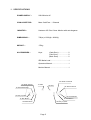
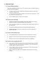
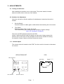
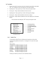
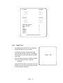
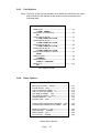
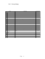
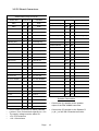
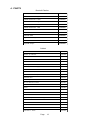
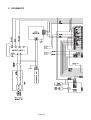
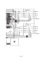
®
™
Operators Manual
IT
IS THE RESPONSIBILITY OF THE OPERATOR TO MAINTAIN CUSTOMER SAFETY
AT ALL TIMES , AND IT IS IMPERATIVE THAT THE DETAILS SET OUT IN THIS
MANUAL ARE FOLLOWED PRECISELY.
Part No. 90500084
© 1995
all rights reserved.
No part of this publication may be reproduced by any mechanical, photographic or
electronic process, or in the form of phonographic recording, nor may it be stored in a
retrieval system, transmitted or otherwise copied for public or private use, without
permission from
NAMCO EUROPE LTD.
While the information contained in this manual is given in good faith and was accurate
at the time of publication, NAMCO EUROPE LTD. reserve the right to make changes
and alterations without notice.
This machine has been manufactured in accordance with European Community
directives (1st. January 1996), and as such bears the marking. Any changes or
modifications to this machine must be in accordance with European Community
directives (1st. January 1996).
If you make any unauthorised changes to this product, you may contravene European
Community directives (1st. January 1996)
Published by:
NAMCO EUROPE LTD.
Namco House,
8 Acton Park Estate,
The Vale,
London. W3 7QE
Phone:- 0208-324-6000
Fax:- 0208-324-6010
SAFETY WARNING
In order to use this machine safely, be sure to read this Operators Manual carefully
before installation, adjustment or use of this machine.
Whenever the owner of this machine entrusts disassembly, installation, adjustment,
routine maintenance or trouble shooting to another person, the owner should ensure that
that person read the appropriate precautions and relevant sections of this manual before
starting work.
In order that no accidents occur when the machine is in operation, strictly follow
the notes on safety described below. Also, carefully read section 2, “Precautions”
Warnings for Operation (
NOTE:
NOTE:
Requirements)
Only operate this machine after checking that it has been installed
correctly and in accordance with the installation and commisioning
manual.
If there is an error or problem with this machine, operation must be
stopped immediately and the problem rectified before further use.
Warnings for Disassembly, Installation, Routine Maintenance, and Troubleshooting.
DANGER:
DANGER:
DANGER:
DANGER:
NOTE:
Namco Ltd. bears absolutely no responsibility for accidents or injuries
resulting from unauthorized changes to this machine.
Ensure that the machine has been turned OFF before making
adjustments or carrying out maintenance. Also ensure only qualified
personnel carry out maintenance or turn the power ON to this
machine.
The power supply and inside the monitor will remain hot and have
areas of high voltage even though the machine has been turned OFF,
and there is a possibility of burns or electric shock. Be careful not to
touch these areas.
In order to avoid injuries due to mis-operation, be sure that the
voltage of the main power supply is within the prescribed limits. Also
to prevent possible electric shocks due to failure, this machine MUST
be fitted with a securely connected earthed plug.
Do not turn the power switch ON until the machine has been installed
correctly.
Contents
Operators Manual ...................................................................................1
SAFETY WARNING .................................................................................3
1.
SPECIFICATIONS .............................................................................5
2.
PRECAUTIONS ................................................................................6
2-1 Cautions When Installing. ...............................................................6
2-2 Cautions when Handling. ...........................................................................6
2-3 Cautions when Transporting....................................................................... 6
2-4 Cautions when handling the PCB. ..............................................................6
3.
ADJUSTMENTS................................................................................7
3-1 Turning on the Power ................................................................................. 7
3-2 Switches for Adjustment .............................................................................7
3-4 Test Mode ...................................................................................................8
3-4-1 Switch Test ....................................................................................8
3-4-2 Sound Test ....................................................................................9
3-4-3 Coin Options ................................................................................ 10
3-4-4 Game Options ............................................................................. 10
3-4-5 Factory Settings........................................................................... 11
3-5 PC Board Connectors .............................................................................. 12
4.
PARTS.............................................................................................13
5.
SCHEMATIC ...................................................................................14
Page 4
1. SPECIFICATIONS
POWER SUPPLY :-
220/240volts AC
COIN ACCEPTOR:-
Mars CashFlow - 1 Channel
MONITOR :-
Hantarex 28" Polo Colour Monitor with auto degauss.
DIMENSIONS :-
790(w) x 1200(d) x 2080(h)
WEIGHT :-
175kg.
ACCESSORIES :-
Keys:
(Cash Door) ..................... 2
(Coin Door) ...................... 2
(Back Door) ..................... 2
IEC Mains Lead ...................................... 1
Operators Manual ................................... 1
Monitor Manual ....................................... 1
2P Attack Horizontal
1P Attack Vertical
1P Start
2P Start
2P Attack Vertical
1P Attack Horizontal
1P 8way Joystick
2P Guard Button
1P Kick Button
2P Kick Button
1P Guard Button
2P 8way Joystick
Page 5
2. PRECAUTIONS
2-1 Cautions When Installing.
This game is designed for indoor use only. The game must not be installed outdoors or
under the following conditions:a.
In areas directly exposed to sunlight, high humidity, direct water contact, dust,
high heat or extreme cold.
b.
In locations that would present an obstacle in the case of an emergency, i.e. near
fire equipment or emergency exits.
c.
On an unstable surface or subject to floor vibration.
2-2 Cautions when Handling.
a.
AC power must always be turned OFF, and the game disconnected, before
replacing any parts or connecting/disconnecting connectors.
b.
When unplugging the game from an electrical outlet, always grasp the plug, not
the mains lead.
c.
The machine must be earthed with a securely connected earthed plug.
d.
Care must be taken at all times to avoid electric shock when inspecting or
adjusting the game.
2-3 Cautions when Transporting.
a.
Do not subject the game to physical shock when transporting or moving it.
b.
Always return the levellers to the UP position before moving the machine.
c.
Take care not to rope any moulded (plastic) parts when transporting.
2-4 Cautions when handling the PCB.
a.
Never test the PCB for continuity with a multimeter or similar device. The PCB
contains sensitive devices which could be damaged or even destroyed by the
internal voltage of such test equipment.
b.
Foreign matter or dust on the PCB may cause failure. Turn off the power and
clean the PCB with a dry soft brush.
c.
When transporting the PCB ensure adequate packing protection to prevent
damage.
Page
6
3. ADJUSTMENTS
3-1 Turning on the Power
After installing the machine, turn on the power. The power switch is located
above the mains inlet on the rear of the cabinet.
3-2 Switches for Adjustment
Open the coin door to find the switches for adjustments, located on the service
bracket.
1.
Service Switch
Press this switch to obtain game credits without incrementing the coin counter.
2.
Test Switch
Slide this switch "ON" to enter test mode.
Test mode allows game testing and the changing of game settings.
(See "3-4 Test Mode" on page 8)
There are two DIP switches located on the PCB.
Switch 1 when set ON will enter the game into test mode. Always ensure this
switch is set to OFF and use the test switch on the service bracket for testing
the machine. Switch 2 when set ON will freeze the screen.
3-3 Volume Adjust
The volume control is located on the PCB. Turn the control to increase or decrease
the volume.
PCB
SERVICE BRACKET
COIN COUNTER
56W edge connector
(JAMMA)
48W extended
edge connector
12
Volume
Option Switch
TEST SWITCH
SERVICE SWITCH
Page
7
3-4 Test Mode
1.
Open the coin door for access to the service bracket, then slide the test switch
"ON". The "Test Menu Screen" will appear on the monitor display.
2.
Operating the 1 Player joystick up or down will step through the items.
3.
Pressing the 1 Player Attack (H) Button will select an item.
4.
Operating the 1 Player joystick up or down will change the settings.
5.
Pressing the 1 Player Attack (H) Button will store the change.
6.
Pressing the 1 Player Attack (V) Button will return the display to the Test Menu
Screen.
The test switch must always be "OFF" during normal game mode.
SWITCH TEST .......................................... For testing switches
SOUND TEST ........................................... For testing the sound
COIN OPTIONS ........................................ For setting game pricing
GAME OPTIONS ...................................... For setting of difficulty etc.
UARTS TEST ............................................ Not Used
POLYGON TEST ...................................... For testing graphics
A.D.S ......................................................... Not Used
COLOR TEST ........................................... For monitor set-up
CONVERGENCE TEST ............................ For monitor set-up
RS-232C TEST ......................................... Not Used
Test Menu Screen
3-4-1
Switch Test
On entering the switch Test, the following screen appears on the monitor.
Operating the joysticks will cause the + to change to X for each of the eight
positions.
When testing:
1P Attack (H) 1P 0000 will change to 1P 1000
1P Attack (V) 1P 0000 will change to 1P 2000
1P Kick
3P 0000 will change to 3P 1000
1P Guard
3P 0000 will change to 3P 2000
2P Attack (H) 2P 0000 will change to 2P 1000
2P Attack (V) 2P 0000 will change to 2P 2000
2P Kick
4P 0000 will change to 4P 1000
2P Guard
4P 0000 will change to 4P 2000
Pressing 1P Attack (V) will return to the Test Menu Screen
Page
8
1P 0000
2P 0000
+ + +
+ X +
+ + +
+ + +
+ X +
+ + +
3P 0000
4P 0000
+ + +
+ X +
+ + +
+ + +
+ X +
+ + +
SERVICE SWITCH
TEST SWITCH
DIP 1
DIP 2
COIN 1
COIN 2
COIN 3
COIN 4
+
X
+
+
+
+
+
+
PRESS ATTACK (V) TO EXIT
3-4-2
Sound Test
On entering the Sound Test, the following
display will appear on the monitor.
Pushing the 1 player joystick to the right
will make the number step up and pushing
the joystick to the left will make the number
step down.
Each number will produce a different sound
when the 1 player Punch 1 button is
pressed.
Song 001 will produce a tone first on the left
speaker, then on the right speaker and then
on both speakers together.
Page
9
SONG
000
3-4-3
Coin Options
Note:- The price of play on this machine is set within the CashFlow coin mech.
Ensure that the coin options on the screen are set as shown in the
following table.
GAME OPTIONS
GAME COST --------------------------------------------------- (1)
1 COIN 1 CREDIT
DISCOUNT TO CONTINUE -------------------------------- (2)
NO
COIN 1 MECH VALUE --------------------------------------- (3)
1 COIN COUNT AS 1 COIN
COIN 2 MECH VALUE --------------------------------------- (4)
1 COIN COUNT AS 1 COIN
COIN 3 MECH VALUE --------------------------------------- (5)
1 COIN COUNT AS 1 COIN
COIN 4 MECH VALUE --------------------------------------- (6)
1 COIN COUNT AS 1 COIN
BONUS FOR QUANTITY BUY-IN ------------------------ (7)
NONE
CREDIT MODE ------------------------------------------------ (8)
COMMON
COIN COUNTER ---------------------------------------------- (9)
TYPE A: 1 COUNTER
FREE PLAY --------------------------------------------------- (10)
NO
Coin Option Screen
3-4-4
Game Options
GAME OPTIONS
DIFFICULTY LEVEL : HARD ------------------------------ (11)
STAGE WIDTH : 18 M --------------------------------------- (12)
FIGHT COUNT(1P GAME) : 2 ---------------------------- (13)
FIGHT COUNT (2P GAME) : 2 --------------------------- (14)
LIFE BAR (IP GAME) : 110% ----------------------------- (15)
LIFE BAR (2P GAME) : 125% ---------------------------- (16)
GUARD DAMAGE : OFF ----------------------------------- (17)
ROUND TIME : 40sec -------------------------------------- (18)
CHARACTER CHANGE AT CONTINUE : YES ------ (19)
CHARACTER CHANGE AT 2P GAME : YES --------- (20)
MUSIC IN ATTRACT : YES ------------------------------- (21)
SPEAKER OUT : STEREO -------------------------------- (22)
EVENT MODE : OFF ---------------------------------------- (23)
HIT COLOUR : GREEN ------------------------------------ (24)
Game Option Screen
Page
10
3-4-5
Factory Settings
ITEM
CONTENTS
FACTORY SET
1
GAME COST
COIN PULSES REQUIRED FOR CREDIT ----- settable 1 - 9
2
DISCOUNT
50% DISCOUNT FOR CONTINUE ----- YES / NO
3
COIN 1 MECH VALUE
NUMBER OF PULSES ON METER ----- settable 1 - 9
1
4
COIN 2 MECH VALUE
NUMBER OF PULSES ON METER ----- settable 1 - 9
1
5&6
1
NO
NOT USED
7
BONUS COIN
EXTRA COIN PULSE AT SPECIFIED COINS IN
NONE
8
CREDIT MODE
COMMON (Credit common to player 1 & 2) / EACH ONE (Player 1 & 2 seperate)
9
COIN COUNTER
TYPE A (1 Coin Counter) / TYPE B (2 Coin Counters)
10
FREE PLAY
YES / NO
11
DIFFICULTY LEVEL
EASY / MEDIUM / HARD / VERY HARD / ULTRA HARD
12
STAGE WIDTH
SETS THE SIZE OF COMBAT AREA
13
FIGHT COUNT (1P GAME)
Settable 1 - 4
2
14
FIGHT COUNT (2P GAME)
Settable 1 - 4
2
15
LIFE BAR (1P GAME)
95 / 110 / 125 / 140 / 160
110
16
LIFE BAR (2P GAME)
95 / 110 / 125 / 140 / 160
125
17
GUARD DAMAGE
OFF / ON (ON : A Character is damaged a little even when blocking)
OFF
18
ROUND TIME
20sec / 30sec / 40sec / 50sec / 60sec
40sec
19
CHARACTER CHANGE AT
CONTINUE
YES/NO
YES
20
CHARACTER CHANGE AT 2P
YES / NO
GAME
YES
21
MUSIC IN ATTRACT
YES / NO
YES
22
SPEAKER OUT
STEREO / MONO
23
EVENT MODE
OFF / ON (Game is over per each 2P game)
24
HIT COLOUR
GREEN / RED
COMMON
TYPE A
NO
HARD
18 M
STEREO
OFF
GREEN
Page
11
3-5 PC Board Connectors
JAMMA 56way Edge Connector
Solder Side
Terminal No
48w Extended Edge Connector
Part Side
Solder Side
Speaker R (-)
GND
A
1
GND
GND
B
2
+5v
C
+5v
Terminal No
Part Side
A1
B1
GND
A2
B2
3
+5v
A3
B3
D
4
+5v
A4
B4
E
5
A5
B5
F
6
A6
B6
Polarizing Key
H
7
Polarizing Key
A7
B7
Coin Counter 2
j
8
Coin Counter 1
A8
B8
K
9
Coin Lockout
A9
B9
GND
Speaker (-)
L
10
Speaker (+)
A10
B10
GND
Audio (GND)
M
11
Audio (+)
A11
B11
Video GREEN
N
12
Video RED
A12
B12
Video SYNC
P
13
Video BLUE
A13
B13
Service Switch
R
14
Video GND
A14
B14
S
15
Test Switch
A15
B15
Coin Switch 2
T
16
Coin Switch 1
A16
B16
2P Start Switch
U
17
1P Start Switch
A17
B17
2P Lever UP
V
18
1P Lever UP
A18
B18
2P Lever DOWN
W
1P Lever DOWN
A19
B19
2P Lever LEFT
X
1P Lever LEFT
A20
B20
2P Lever RIGHT
Y
1P Lever RIGHT
A21
B21
2P Attack - H
Z
22
1P Attack - H
A22
B22
2P Attack - V
a
23
1P Attack - V
A23
B23
2P Kick
b
24
1P Kick
A24
B24
c
25
d
26
GND
e
27
GND
GND
f
28
GND
+12v
•
•
•
•
•
Polarizing Key
+12v
2PGuard Button
1P Guard Button
Speaker R (+)
Polarizing Key
Speaker Connections
Do not make connections to blank positions.
Lockout / Coin Counter both operate on +12v.
The supply voltage must be within 5%.
+5V / 2.5A minimum
+12v / 2A minimum
Page
•
Connect the (L) speaker to the speaker
output of the 56w JAMMA connector
•
Connect the (R) speaker to the Speaker R
(+) & (-) of the 48w Extended connector
12
4. PARTS
Decals & Plastics
DESCRIPTION
PART No.
Cabinet Decal LHS - Upper
40000290
Cabinet Decal LHS - Lower
40000291
Cabinet Decal RHS - Upper
40000292
Cabinet Decal RHS - Lower
40000293
Cabinet Decal Front - LHS
40000294
Cabinet Decal Front - RHS
40000295
Cabinet Decal "NAMCO" LHS/RHS/Front
40000061
Character Plexi
30000225
Play Panel Overlay
33000120
Header Box Vac-Form
45000728
Top Flash Acrylic
30000226
Cabinet
DESCRIPTION
PART No.
Monitor 28" Hantarex
84000026
Front Glass - Bronze
31000022
Interlock Switch
60000006
Interlock Switch Cover
39000028
M16 Adjustable Foot
88300079
Switch Mode Power Supply
83000002
Mains Filter
67000303
Speaker 4½" 20w (with shield can)
62000006
Schaffner Mains In Assy
66000016
Schaffner Boot
66000017
Fuse 5amp 20mm Slo-Blo
63500600
18" 15w Fluorescent Tube
64500009
Choke 240v 15w
63300000
Starter
63000000
Service Switch - SPNO
60000059
Test Switch - DPCO
60000023
3.5 - 6v Panel Meter
65000002
Joystick 8way Brent Fast Action Type
61000017
Push Button - Yellow
60200266
Push Button - Green
60200267
Push Button - Red
60200264
Push Button - Blue
60200263
Push Button - White
60200262
Page
13
5. SCHEMATIC
Page 14
Page 15