1
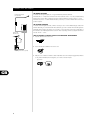
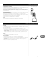
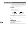
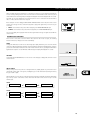
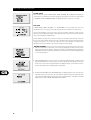
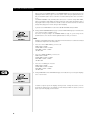
L75
Surround Sound Receiver
GB Owner’s Manual
F
Manuel d’Installation
D
Bedienungsanleitung
E
Manual del Usuario
I
Manuale delle Istruzioni
P
Manual do Proprietário
S
Bruksanvisning
IMPORTANT SAFETY INSTRUCTIONS
CAUTION
• Read all of these instructions.
• Save these instructions for later use.
• Follow all warnings and instructions marked on the audio equipment.
1 Read instructions - All the safety and operating instructions should be read before the product is
operated.
2 Retain instructions - The safety and operating instructions should be retained for future reference.
3 Heed Warnings - All warnings on the product and in the operating instructions should be adhered
to.
4 Follow Instructions - All operating and use instructions should be followed.
5 Cleaning - Unplug this product from the wall outlet before cleaning. Do not use liquid cleaners or
aerosol cleaners. Use a damp cloth for cleaning.
6 Attachments - Do not use attachments not recommended by the product manufacturer as they may
cause hazards.
7 Water and Moisture - Do not use this product near water-for example, near a bath tub, wash bowl,
kitchen sink, or laundry tub; in a wet basement; or near a swimming pool; and the like.
8 Accessories - Do not place this product on an unstable cart, stand, tripod, bracket, or table. The
product may fall, causing serious injury to a child or adult, and serious damage to the product. Use only
with a cart, stand, tripod, bracket, or table recommended by the manufacturer, or sold with the
product. Any mounting of the product should follow the manufacturer’s instructions, and should use
a mounting accessory recommended by the manufacturer.
9 A product and cart combination should be moved with care. Quick stops, excessive force, and uneven
surfaces may cause the product and cart combination to overturn.
10 Ventilation - Slots and openings in the cabinet are provided for ventilation and to ensure reliable
operation of the product and to protect it from overheating, and these openings must not be blocked
or covered. The openings should never be blocked by placing the product on a bed, sofa, rug, or other
similar surface. This product should not be placed in a built-in installation such as a bookcase or rack
unless proper ventilation is provided or the manufacturer’s instructions have been adhered to.
11 Power Sources - This product should be operated only from the type of power source indicated on
the marking label. If you are not sure of the type of power supply to your home, consult your product
dealer or local power company. For products intended to operate from battery power, or other sources,
refer to the operating instructions.
12 Grounding or Polarization - This product may be equipped with a polarized alternating-current line
plug (a plug having one blade wider than the other). This plug will fit into the power outlet only one
way. This is a safety feature. If you are unable to insert the plug fully into the outlet, try reversing the
plug. If the plug should still fail to fit, contact your electrician to replace your obsolete outlet. Do not
defeat the safety purpose of the polarized plug.
13 Power-Cord Protection - Power-supply cords should be routed so that they are not likely to be walked
on or pinched by items placed upon or against them, paying particular attention to cords at plugs,
convenience receptacles, and the point where they exit from the product.
14 Outdoor Antenna Grounding - If an outside antenna or cable system is connected to the product,
be sure the antenna or cable system is grounded so as to provide some protection against voltage
surges and built-up static charges. Article 810 of the National Electrical Code, ANSI/NFPA 70, provides
information with regard to proper grounding of the mast and supporting structure, grounding of the
lead-in wire to an antenna discharge unit, size of grounding conductors, location of antenna-discharge
unit, connection to grounding electrodes, and requirements for the grounding electrode.
GB
2
IMPORTANT SAFETY INSTRUCTIONS
NOTE TO CATV SYSTEM INSTALLER
This reminder is provided to call the CATV system installer’s attention to Section 820-40 of the NEC
which provides guidelines for proper grounding and, in particular, specifies that the cable ground shall
be connected to the grounding system of the building, as close to the point of cable entry as practical.
Example of Antenna Grounding as per National Electrical Code, ANSI/NFPA 70
ANTENNA LEAD IN WIRE
GROUND CLAMP
ANTENNA DISCHARGE UNIT
ELECTRIC SERVICE
EQUIPMENT
GROUNDING CONDUCTORS
GROUND CLAMPS
POWER SERVICE GROUNDING ELECTRODE
SYSTEM
15 Lightning - For added protection for this product during a lightning storm, or when it is left
unattended and unused for long periods of time, unplug it from the wall outlet and disconnect the
antenna or cable system. This will prevent damage to the product due to lightning and power-line
surges.
16 Power Lines - An outside antenna system should not be located in the vicinity of overhead power lines
or other electric light or power circuits, or where it can fall into such power lines or circuits. When
installing an outside antenna system, extreme care should be taken to keep from touching such power
lines or circuits as contact with them might be fatal.
17 Overloading - Do not overload wall outlets, extension cords, or integral convenience receptacles as
this can result in a risk of fire or electric shock.
18 Object and Liquid Entry - Never push objects of any kind into this product through openings as they
may touch dangerous voltage points or short-out parts that could result in a fire or electric shock. Never
spill liquid of any kind on the product.
19 Servicing - Do not attempt to service this product yourself as opening or removing covers may expose
you to dangerous voltage or other hazards. Refer all servicing to qualified service personnel.
20 Damage Requiring Service - Unplug this product from the wall outlet and refer servicing to qualified
service personnel under the following conditions:
a) When the power-supply cord or plug is damaged.
b) If liquid has been spilled, or objects have fallen into the product.
c) If the product has been exposed to rain or water.
d) If the product does not operate normally by following the operating instructions. Adjust only those
controls that are covered by the operating instructions as an improper adjustment of other controls
may result in damage and will often require extensive work by a qualified technician to restore the
product to its normal operation.
e) If the product has been dropped or damaged in any way.
f) when the product exhibits a distinct change in performance-this indicates a need for service.
21 Replacement Parts - When replacement parts are required, be sure the service technician has used
replacement parts specified by the manufacturer or have the same characteristics as the original part.
Unauthorized substitutions may result in fire, electric shock, or other hazards.
22 Safety Check - Upon completion of any service or repairs to this product, ask the service technician to
perform safety checks to determine that the product is in proper operating condition.
23 Wall or Ceiling Mounting - The product should be mounted to a wall or ceiling only as recommended
by the manufacturer.
24 Heat - The product should be situated away from heat sources such as radiators, heat registers, stoves,
or other products (including amplifiers) that produce heat.
GB
3
IMPORTANT SAFETY INSTRUCTIONS
WARNING
TO PREVENT FIRE OR SHOCK HAZARD, DO NOT EXPOSE THIS APPLIANCE TO RAIN OR MOISTURE.
THE LIGHTNING FLASH WITH ARROWHEAD SYMBOL, WITHIN AN EQUILATERAL TRIANGLE, IS
INTENDED TO ALERT THE USER TO THE PRESENCE OF UNINSULATED “DANGEROUS VOLTAGE”
WITHIN THE PRODUCT’S ENCLOSURE THAT MAY BE OF SUFFICIENT MAGNITUDE TO
CONSTITUTE A RISK OF ELECTRIC SHOCK TO PERSONS.
THE EXCLAMATION POINT WITHIN AN EQUILATERAL TRIANGLE IS INTENDED TO ALERT THE
USER TO THE PRESENCE OF IMPORTANT OPERATING AND MAINTENANCE (SERVICING)
INSTRUCTIONS IN THE LITERATURE ACCOMPANYING THE APPLIANCE
The equipment draws its nominal non-operational power from the AC outlet with its POWER switch in the
STANDBY position.
CAUTION
Changes or modifications to this equipment not expressly approved by NAD Electronics for compliance
could void the user’s authority to operate this equipment.
CAUTION REGARDING PLACEMENT
To maintain proper ventilation, be sure to leave a space around the unit (from the largest outer dimensions
including projections) equal to, or greater than, shown below.
Left and Right Panels : 10 cm
Rear Panel : 10 cm
Top Panel : 50 cm
IMPORTANT INFORMATION FOR UK CUSTOMERS
DO NOT cut off the mains plug from this equipment. If the plug fitted is not suitable for the power points
in your home or the cable is too short to reach a power point, then obtain an appropriate safety approved
extension lead or consult your dealer. If, nonetheless, the mains plug is cut off, REMOVE THE FUSE and
dispose of the PLUG immediately, to avoid possible shock hazard by inadvertent connection to the mains
supply. If this product is not provided with a mains plug, or one has to be fitted, then follow the instructions
given below:
IMPORTANT
DO NOT make any connection to the larger terminal which is marked with the letter ‘E’ or by the safety
earth symbol or coloured GREEN or GREEN AND YELLOW.
GB
The wires in the mains lead on this product are coloured in accordance with the following code:
BLUE - NEUTRAL
BROWN - LIVE
As these colours may not correspond with the coloured markings identifiying the terminals in your plug,
proceed as follows:
The BLUE wire must be connected to the terminal marked with the letter ‘N’ or coloured BLACK.
The BROWN wire must be connected to the terminal marked with the letter ‘L’ or coloured RED
When replacing the fuse, only a correctly rated and approved type should be used, and be sure
to re-fit the fuse cover.
IF IN DOUBT CONSULT A COMPETENT ELECTRICIAN
4
BEFORE USE
READ THIS BEFORE OPERATION
• Choose the installation location of your unit carefully. Avoid placing it in direct sunlight or close to a
source of heat. Also avoid locations subject to vibrations and excessive dust, heat, cold or moisture.
• The ventilation holes should not be covered. Make sure there is at least 50 cm of space above and at
least 10 cm of space beside the amplifier/receiver. Do not place a CD player or other equipment on top
of the amplifier/receiver.
• Do not open the cabinet as this might result in damage to the circuitry or electrical shock. If a foreign
object should get into the set, contact your dealer.
• When removing the power plug from the wall outlet, always pull directly on the plug, never yank the
cord.
• The ventilation should not be impeded by covering the ventilation openings with items, such as
newspapers, table-cloths, curtains, etc.
• No naked flame sources, such as lighted candles, should be placed on the apparatus.
• The apparatus should not be exposed to dripping or splashing and no objects filled with liquids, such
as vases, should be placed on the apparatus.
• This apparatus is designed to be used in moderate climates.
ABOUT THE POWER SWITCH
This unit is not equipped with a
primary power switch. Even when
the units STANDBY/ON button is
set to STANDBY (off). the power
supply to this unit is not
completely turned off. If you wish
to completely turn the power off,
disconnect the power cord from
the household AC outlet.
CONTENTS
Important Safety Instruction . . . . . . . . . . . . . . . . . . . . . . . . . . . . . . . . . . . . . . . . . . . . . . . . . .2-4
Before Use . . . . . . . . . . . . . . . . . . . . . . . . . . . . . . . . . . . . . . . . . . . . . . . . . . . . . . . . . . . . . . . . . .5
Connecting Antennas . . . . . . . . . . . . . . . . . . . . . . . . . . . . . . . . . . . . . . . . . . . . . . . . . . . . . . . .6-7
Connecting Speaker Systems . . . . . . . . . . . . . . . . . . . . . . . . . . . . . . . . . . . . . . . . . . . . . . . . . . .7
Connecting Audio Equipment . . . . . . . . . . . . . . . . . . . . . . . . . . . . . . . . . . . . . . . . . . . . . . . . . . .8
Connecting Video Equipment . . . . . . . . . . . . . . . . . . . . . . . . . . . . . . . . . . . . . . . . . . . . . . . . . . .9
Connecting Digital Audio Output Equipment . . . . . . . . . . . . . . . . . . . . . . . . . . . . . . . . . . . . . . .9
Audio Operation . . . . . . . . . . . . . . . . . . . . . . . . . . . . . . . . . . . . . . . . . . . . . . . . . . . . . . . . . .10-11
Audio Adjustments . . . . . . . . . . . . . . . . . . . . . . . . . . . . . . . . . . . . . . . . . . . . . . . . . . . . . . . . . .11
Radio Reception . . . . . . . . . . . . . . . . . . . . . . . . . . . . . . . . . . . . . . . . . . . . . . . . . . . . . . . . . . . . .13
Auto Tuning . . . . . . . . . . . . . . . . . . . . . . . . . . . . . . . . . . . . . . . . . . . . . . . . . . . . . . . . . . . . . . 13
Manual Tuning . . . . . . . . . . . . . . . . . . . . . . . . . . . . . . . . . . . . . . . . . . . . . . . . . . . . . . . . . . . . 13
Automatic Memory Presetting . . . . . . . . . . . . . . . . . . . . . . . . . . . . . . . . . . . . . . . . . . . . . . . . . 13
Manual Memory Presetting . . . . . . . . . . . . . . . . . . . . . . . . . . . . . . . . . . . . . . . . . . . . . . . . . . . 13
Deleting a stored preset . . . . . . . . . . . . . . . . . . . . . . . . . . . . . . . . . . . . . . . . . . . . . . . . . . . . . . 13
RDS (Radio Data System) . . . . . . . . . . . . . . . . . . . . . . . . . . . . . . . . . . . . . . . . . . . . . . . . . . . . . .14
Clock /On time/Off time adjust . . . . . . . . . . . . . . . . . . . . . . . . . . . . . . . . . . . . . . . . . . . . . . . . .14
Available Surround Modes . . . . . . . . . . . . . . . . . . . . . . . . . . . . . . . . . . . . . . . . . . . . . . . . . .15-16
Speaker Positioning . . . . . . . . . . . . . . . . . . . . . . . . . . . . . . . . . . . . . . . . . . . . . . . . . . . . . . . . . .17
Speaker Configuration . . . . . . . . . . . . . . . . . . . . . . . . . . . . . . . . . . . . . . . . . . . . . . . . . . . . . . . .17
Surround Effects . . . . . . . . . . . . . . . . . . . . . . . . . . . . . . . . . . . . . . . . . . . . . . . . . . . . . . . . . . . . .18
Delay Time . . . . . . . . . . . . . . . . . . . . . . . . . . . . . . . . . . . . . . . . . . . . . . . . . . . . . . . . . . . . . . . 18
OSD (On Screen Display) . . . . . . . . . . . . . . . . . . . . . . . . . . . . . . . . . . . . . . . . . . . . . . . . . . . .19-22
Automatic OSD function . . . . . . . . . . . . . . . . . . . . . . . . . . . . . . . . . . . . . . . . . . . . . . . . . . . 19-20
OSD ON Position . . . . . . . . . . . . . . . . . . . . . . . . . . . . . . . . . . . . . . . . . . . . . . . . . . . . . . . . . 20-22
Remote Control Unit . . . . . . . . . . . . . . . . . . . . . . . . . . . . . . . . . . . . . . . . . . . . . . . . . . . . . . . . .23
Using the Remote Control Unit . . . . . . . . . . . . . . . . . . . . . . . . . . . . . . . . . . . . . . . . . . . . . . . . 23
Battery Installation . . . . . . . . . . . . . . . . . . . . . . . . . . . . . . . . . . . . . . . . . . . . . . . . . . . . . . . . . . 23
Troubleshooting . . . . . . . . . . . . . . . . . . . . . . . . . . . . . . . . . . . . . . . . . . . . . . . . . . . . . . . . . . . . .24
Specifications . . . . . . . . . . . . . . . . . . . . . . . . . . . . . . . . . . . . . . . . . . . . . . . . . . . . . . . . . . . . . . .25
GB
5
CONNECTING ANTENNAS
Lead-type FM Antenna
(75Ω) provided
Outdoor FM
Antenna (75Ω)
FM INDOOR ANTENNA
In an area with strong FM signals, the “T”-type FM antenna provided is sufficient.
Extend this into a “T” shape and connect the two wires at the base of the “T” to the provided matching
transformer, as shown. After completing connection, plug the transformer into the “FM 75Ω“ socket.
Extend the top of the “T” and fix with thumb tacks, or the like, to a wall or window frame for the best
possible reception.
FM OUTDOOR ANTENNA
In an area where FM signals are weak, it will be necessary to use a 75-ohm unbalanced-type outdoor FM
antenna. Generally, a 3- element antenna will be sufficient; if you live in an area where the FM signals are
particularly weak, it may be necessary to use one with 5 or more elements. Connect the coaxial cable of
the antenna to the matching transformer as shown. After completing connection, plug the transformer
into the “FM 75Ω“ socket.
HOW TO CONNECT A COAXIAL CABLE TO THE MATCHING TRANSFORMER
1 Strip the cable and dress it as shown.
2 Press both side tabs outward to remove the cover.
Matching Transformer (optional)
3 Wrap the core conductor around the central metal fixture as shown. Crimp the jagged metal fixtures
so they hold the braided portion using pliers, etc. Put the cover back in place.
jagged metal
Insert into slit.
GB
6
CONNECTING ANTENNAS
AM INDOOR LOOP ANTENNA
The high-performance AM loop antenna provided with the receiver is sufficient for good reception in most
areas. Connect the loop antenna’s wires to the AM antenna terminals as shown.
Place the antenna on a shelf, for example, or hang it on a window frame, etc., in the direction which gives
the best reception, as far away as possible from the entire system, speaker cords and the power cord, to
prevent unwanted noise.
AM Loop Antenna (provided)
AM OUTDOOR ANTENNA
If the AM loop antenna provided does not deliver sufficient reception (because you are too far from the
transmitter or in a concrete building, etc.), it may be necessary to use an outdoor AM antenna.
Use an insulated wire more than 15 ft (5 m) long, strip one end, and connect this to the terminal as shown.
The antenna wire should be strung outdoors or indoors near a window.
For better reception, connect the GND terminal to a reliable ground.
NOTE
Even when using an outdoor AM antenna, do not disconnect the AM loop antenna.
CONNECTING SPEAKER SYSTEMS
CAUTION
To avoid damage the speakers by inputting a sudden high-level signal, be sure to switch the power off
before connecting the speakers.
Connect the cable from each speaker to the corresponding terminal on the rear of the receiver.
• Most speaker cables have different markings, textures or colors to help you tell the difference between
negative and positive.
• Be sure to connect the positive (+) terminal on each speaker to the positive (+) terminal on the receiver.
Similarly, connect the negative (-) terminal on the speaker to negative (-) terminal on the receiver.
NOTES
• Use speakers with a nominal impedance of 8 ohms or more.
GB
HOW TO CONNECT
1 Strip back the cable covering by about 1 cm and twist the wire strands together.
2 Turn the terminal cap counterclockwise to loosen it. The speaker terminal caps cannot be fully removed
from the base.
3 Insert the wire into the terminal fully and turn the terminal cap clockwise to securely connect it.
4 Make sure it is fastened firm by pulling the cable lightly.
7
CONNECTING AUDIO EQUIPMENT
CAUTION
• Do not plug the power cord of any component into AC outlets and do not turn their POWER switches
on until all connections have been performed.
• The cable connectors should be fully inserted into the jacks. Loose connections may cause hum and
noise.
• Read the instructions for each component you intend to use with the receiver.
AUDIO SIGNAL JACKS
AUX IN jacks Connect the Auxiliary output jacks to the AUX IN jacks.
TAPE (IN/OUT) jacks
• Connect the TAPE jacks to the cassette deck.
• Connect the cassette deck output (LINE OUT)jacks to the IN jacks.
• Connect the cassette deck output (LINE IN)jacks to the OUT jacks.
White
White
L
L
R
R
Red
Red
AUDIO CONNECTION CORDS
To make these connections, use interconnect cords with RCA plugs. Make sure that you connect the white
pin-plug to the white jacks (left) and the red pin-plug to the red jacks (right).
CONNECTING THE PRE OUT JACKS
Since subwoofer signals are not amplified, use a subwoofer with a built-in amplifier or connect it to the
amplifier connected to this unit.
NOTE
• If a speaker is connected directly to the PRE OUT jack without an amplifier connected, no sound comes
from the speaker.
CONNECTING THE AC POWER
Be sure to connect the power cord to an AC outlet which supplies the correct voltage.
• Hold the power plug when plugging or unplugging the power cord.
GB
AC OUTLETS (AH VERSION)
CAUTION
Make sure that the total power consumption of all equipment connected to the outlets on the receiver
does not exceed 100 watts.
8
CONNECTING VIDEO EQUIPMENT
AUDIO SIGNAL JACKS
• Connect the video deck (VCR) LINE output (AUDIO OUT) jacks to the IN (VIDEO 1) jacks, and the video
deck (VCR) LINE input (AUDIO IN) jacks to the OUT (VIDEO 1) jacks.
• Connect the LD player AUDIO OUTPUT jacks to the VIDEO 2 jacks.
• Connect the DVD player’s analogue Left and Right AUDIO OUTPUT jacks to the DVD jacks.
VIDEO SIGNAL JACKS
• Connect the TV monitor VIDEO IN jack to the MONITOR OUT jack.
• Connect the video deck (VCR) VIDEO OUT (VIDEO) jack to the IN (VIDEO 1) jack. Connect the video
deck (VCR) VIDEO IN jacks to the OUT (VIDEO 1) jack.
• Connect the LD player VIDEO OUTPUT jacks to the VIDEO 2 IN jack.
• Connect the DVD player or Decoder VIDEO OUTPUT jacks to the DVD IN jacks.
S-VIDEO SIGNAL JACKS
• Connect the TV monitor S-VIDEO IN jack to the MONITOR OUT jack.
• Connect the video deck (VCR) S-VIDEO OUT jack to the S-VIDEO VIDEO1 IN jack. Connect the video
deck (VCR) S-VIDEO IN jack to the S-VIDEO VIDEO1 OUT jack.
• Connect the LD player S-VIDEO OUTPUT jacks to the VIDEO2 IN jack.
• Connect the DVD or Decoder S-VIDEO OUTPUT jacks to the S-VIDEO DVD IN jack.
NOTES
• The FUNCTION (source) selector for the S-VIDEO inputs and VIDEO inputs work in conjunction with
each other.
• This unit’s S-VIDEO (IN/OUT) jacks and VIDEO (IN/OUT) pin jacks have independent circuit structures, so
that video signals input from the S-VIDEO jacks are only output from the S-VIDEO jack outputs and
video signals input from the VIDEO pin jacks are only output from the VIDEO pin jack outputs.
DOLBY DIGITAL (AC-3)/DTS/PCM DIGITAL IN JACKS
• If the DVD player or Decoder is provided with either a coaxial or optical digital output, connect to
respectively DVD Coaxial or Digital input.
• If a Digital music source, such as MiniDisc or MP3 player is provided an optical digital output, connect
to AUX Digital input.
• When an optical connection is used for connection, remove the caps protecting both ends of the
optical cable and the connectors. Remove the protective cap from the input socket.
DIGITAL OUT (OPTICAL AND COAXIAL)
• Connect the coaxial or optical digital input on CD or MiniDisk Recorder to the coaxial respectively
optical Digital output of the L75.
GB
NOTES
Do not connect both the coaxial and optical Digital Outputs to the corresponding Digital inputs on the
same recording device.
9
AUDIO OPERATIONS
NOTES
The following points apply throughout the “Audio Operations”
sections unless otherwise noted. To simplify explanations, instructions
refer to names of buttons and controls on the front panel, making
no mention of the use of remote control unit.
PRIVATE LISTENING
For private listening, insert the headphones (1/4-inch plug) into the
PHONES jack.
PHONES
NOTE
When playing movie or music with 5.1 channels through Dolby
Digital or DTS, multi-channel signal will be automatically down-mixed
to 2-channel stereo. VFL Display will show ‘Digital stereo’ icon or
‘DTS stereo’ icon. The output via speakers will be muted.
MUTING BUTTON (ON THE REMOTE CONTROL UNIT)
Press this to mute the sound from the speakers and headphones when
answering the telephone, etc. To restore the original volume, press the
MUTING button again. While Muting is engaged, the Display will say
“MUTE”.
SLEEP
SLEEP TIMER OPERATION
SLEEP Timer Function (on the Remote Control Unit)
This function allows you to preprogram the receiver to switch its own
power off automatically. You can then enjoy the audio/video system for
a specified amount of time without having to worry about turning the
unit off later. Each press of the SLEEP button changes the time indication
by 10 minutes.
SLEEP 90
SLEEP 80
SLEEP 10
Released condition
To let the remaining time (until power off) appear on the display while
the sleep timer is engaged, press the SLEEP button once.
GB
WHEN TO USE RESET SWITCH
1 When this system is subjected to an electrical shock.
2 When the power is irregular. In these cases, try the following (in
power standby mode.):
MUTE
Rear Panel
Press the RESET switch lightly once or twice with a pencil or ballpoint pen
NOTE
When the RESET switch is pressed, all the memory will be cancelled.
10
AUDIO OPERATIONS
BASIC OPERATIONS
1 Press the POWER button to ON.
2 Adjust the tone as required with the BASS and TREBLE tone controls. Adjust the balance between the
left and right channels with the BALANCE control.
3 Select the desired source with the Source Selector. An indicator for the selected source lights up.
4 Select the desired surround mode with the SURROUND MODE buttons. (The SURROUND indicator
lights in the display.)
• Refer to available surround modes. (page 12).
• Refer to OSD surround mode. (page 16-17).
5 Start playing the source component.
6 Gradually turn up the volume to the required level with the MASTER VOLUME control.
1
6
2
4
2
3
AUDIO ADJUSTMENTS
1 POWER STANDBY/ON Button Press this button to turn the power on. Press it again to turn the
system off (power standby mode). The STANDBY indicator lights up in power standby mode and goes
out when this unit is turned on.
2 BASS/TREBLE Tone Controls These two tone controls - BASS and TREBLE - can be used to obtain a
“flat” frequency response or a tone which suits your individual listening preference. The Bass control
adjusts low frequencies and the TREBLE control adjusts the high frequencies.
3 BALANCE Control This control is used to adjust the balance between the left and right channels.
Normally set to the center position.
4 MASTER VOLUME Control Adjust the overall sound volume from the front, center, sub woofer and
rear speakers with this control.
5 FM MUTE/MONO This button combines two functions, it switches the tuner from stereo to mono and
disengages the mute circuitry at the same time. The muting circuit will mute the Tuner in between radio
stations when searching or tuning. If FM broadcasts with weak signal strength are received, the FM
muting function works automatically to cut the signals, eliminating loud noise.
6 SURROUND MODE Button Surround mode changes follows whenever you press this button.
• Refer to available surround modes. (page 12)
• Refer to OSD surround mode. (page 16-17)
NOTE
• You can not select DTS/DOLBY DIGITAL mode in Analog mode or except DVD, AUX Function.
• To select DTS/DOLBY DIGITAL mode, you should select optical or coaxial mode by DISPLAY button.
1
5
6
2
4
7
3
GB
7 DISPLAY Button Press this button to switch the digital signal when DVD, AUX selected. Refer to OSD
digital input (page 16).
When DVD selected
Optical
Coaxial
Analog
When AUX selected
Optical
Analog
CAUTION
In tuner function, this button toggles the display to show the PS/RT.
11
RADIO RECEPTION
2
3
4
AUTO TUNING
1 Select the Tuner by turning the Source selector.
2 Select the AM or FM by pressing the AM/FM selector button.
3 Press the Tune/Preset MODE button to change to TUNING mode. (The PRESET CH. indicator disappears
from the display.) This button is used to select Tuning or Preset scan mode.
4 Press the UP or DOWN TUNING button (within 0.5 to 2 seconds). The next station broadcasting at a
frequency higher or lower than that of the current station is automatically detected and tuned in. By
pressing and holding the TUNING button for longer than 2 seconds, it will continue to scan (three times
faster than normal speed).
MANUAL TUNING
Manual Tuning is generally used to tune to stations broadcasting a signal that is too weak to be received
by Auto Tuning.
1 Select the Tuner by turning the Source selector.
2 Select the AM or FM by pressing the AM/FM selector button.
3 Press the Tune/Preset MODE button to change to TUNING mode. (The PRESET CH. indicator disappears
from the display.)
4 When the Tune/Preset Mode button is pressed momentarily (0.5 second or less), the frequency changes
by a fixed step.
EUROPE
FM : 50 kHz steps
AM : 9 kHz steps
AMERICA
FM : 100 kHz steps
AM : 10 kHz steps
• Press the AM/FM button for more than 4 seconds then steps changes.
1
PRESET TUNING
This facility is used to store AM and FM stations in presets from 1 to 30.
2
GB
3
4
1
12
AUTOMATIC MEMORY PRESETTING
1 Select the Tuner by turning the Source selector.
2 Select the AM or FM by pressing the AM/FM selector button.
3 Press the MEMORY button for a while (for more than 1.5 seconds).
a) The start frequency will show in the display:
EUR87.5 MHz in FM, 522 kHz in AM.
AMERICA 87.5 MHz in FM, 530 kHz in AM.
b) The frequency and display will automatically scan.
c) The frequency shown in the display will rapidly change. As each station is located a preset number
will appear in the display indicating which preset MEMORY button has been assigned to the station
located. The scanning process will continue to operate in this fashion until 30 stations have been
found and entered into the preset memory or when there are no more stations to be found on the
waveband chosen. The memory indicator will extinguish and let you hear the last station to be
memorized. To listen to the memorized station select the band required and press the numeric keys
1, 2, 3 etc.
4 The last memorized preset of each band will be displayed when Auto Memory is completed. Check the
programmed frequencies with TUNING/PRESET UP, DOWN button.
RADIO RECEPTION
MANUAL MEMORY PRESETTING
1 Select the Tuner by turning the Source selector.
2 Select the AM or FM by pressing the AM/FM selector button.
3 Press the Tune/Preset MODE button to change to TUNING mode. (The PRESET CH. indicator disappears
from the display).
4 Select the frequency you want to preset by pressing TUNING/PRESET UP or DOWN button.
5 Press the MEMORY button briefly, MEMORY display will blink at an interval of 1 second.
6 While the MEMORY indicator is lit
a) Press the TUNING/PRESET button to be desired selection then press the MEMORY button again, or
b) Press the numeric keys (on the remote control unit) to input the preset number in which the data
for the broadcast is to be stored.
2
3
4,6
5
1
DELETING A STORED PRESET
You can empty a preset by deleting the stored information
1 Select the preset to be emptied.
2 Press and hold Tune/Preset mode button for more than 4 seconds. The preset will then be deleted and
“_ _” appears on the preset number and “DELETED” scrolls on the display.
NOTE
Empty presets will be skipped during preset tuning.
RECALLING FREQUENCIES
Press the numeric key(s) corresponding to the channel number to tune directly to a broadcast.
“BACK-UP” MEMORY FUNCTION
This function conserves the already preset station memories, and “Most-recent” memory function, even
in the event of a cut-off of power supply, as when the plug is pulled out of the wall outlet.
GB
13
RDS (RADIO DATA SYSTEM)
RDS is a broadcasting service which allows stations to send additional information along with the regular
radio program signal. RDS services can be received only in FM band.
2
3
RDS DISPLAY
1 Select the tuner with the Source selector.
2 Press the AM/FM button to select FM.
3 Press the DISPLAY button. Each time you press the button briefly (1.5 sec or less), the modes will change
as follows regardless of the current mode.
PS
RT
RDS OFF
1
CLOCK/ON TIME /OFF TIME ADJUST
1,2
GB
14
3, 5, 7 2, 4, 6, 8
9, 11, 13 10, 12
1 Press and hold the TIMER ON/OFF button for more than 4 seconds. “TIME” scrolls on the display and
then replaced by the current time with the hour blinking at an intervals of 1 second.
2 Adjust the hour by pressing TIME DOWN/UP button. Otherwise press TIMER ON/OFF button briefly to
bypass current time setting and move to On Time Adjust mode. Another press of TIMER ON/OFF button
will bypass On Time setting and move to Off Time setting.
3 Press the MEMORY button briefly. The minutes will blink at an interval of 1 second.
4 Adjust the minute by pressing TIME DOWN/UP button.
5 Press MEMORY button briefly to change to On Time Adjust Mode. “ON TIME” scrolls on the display
and is then replaced by the previously set On Time with the hour blinking at an interval of 1 second.
6 Adjust the hour by pressing TIME DOWN/UP button.
7 Press the MEMORY button briefly. The minute will blink at an interval of 1 second.
8 Adjust the minute by pressing TIME DOWN/UP button.
9 Press MEMORY button briefly to change to Off Time Adjust Mode. “OFF TIME” scrolls on the display
and is then replaced by the previously set Off Time with the hour blinking at an interval of 1 second.
10 Adjust the hour by pressing TIME DOWN/UP button.
11 Press the MEMORY button briefly. The minute will blink at an interval of 1 second.
12 Adjust the minute by pressing TIME DOWN/UP button.
13 Press MEMORY button briefly to change to Normal Mode.
AVAILABLE SURROUND MODES
When you use the surround function, the sound creates a “live” atmosphere such as that experienced in
movie theaters, discos, stadiums and concert halls. This unit is provided with the following surround
modes, which can be selected using the SURROUND MODE switches.
Select the appropriate surround mode according to the program source.
• Note that surround speakers are needed for the Dolby Pro Logic Surround mode to function, and a
center speaker is needed for the 3 Stereo mode to function.
DTS (DIGITAL THEATER SYSTEM)
Allows you to enjoy 5.1 (or 6) discrete channels of high quality digital audio from DTS program sources
bearing the
,
or “HIGH DEFINITION SURROUND” trademark such as discs, DVD and compact
discs, etc. DTS DigitalSurround delivers up to 6 channels of transparent audio (which means identical to
the original masters) and results in exceptional clarity throughout a true 360° soundfield. The term DTS is
a trademark of DTS Technology, LLC. Manufactured under license from DTS Technology, LLC.
SURROUND MODE
NOTE
The DTS program sources should be played back in the DTS mode. If not, it will sound like continuous
noise.
DOLBY DIGITAL SURROUND
The Dolby Digital surround format lets you enjoy up to 5.1 channels of digital surround sound from a Dolby
Digital program source. If you connect a DVD player equipped with an DOLBY DIGITAL output to the
DIGITAL (Dolby Digital) / DTS / PCM DIGITAL IN jack on a surround receiver/amplifier or surround
processor and play DVD with the
mark, you can enjoy even better sound quality, greater spatial
accuracy, and improved dynamic range. This is because Dolby Digital delivers up to 5 totally discrete, full
frequency audio channels (front left and right, center, and surround left and right), plus 0.1 channel called
LFE (bass-only effects channel).
Dolby Digital is a system developed by Dolby Laboratories that transmits 5.1 channels of digital signals. The
surround system developed for movie theaters using this system is called “Dolby SR-D (Surround Digital)”.
Because each channel is completely independent, a realistic sound field with a “three-dimensional” feel is
achieved which gives the sound a sense of distance, movement and relative position, creating a surprisingly
real and powerful sense of presence.
Some Dolby Digital programs carry information that allow you to compress the dynamic range of sound
track, without degrading the sound quality, for softer sound effects when you listen late at night.
LFE: LOW FREQUENCY EXTENSION
This channel delivers separate non-directional bass signals to the subwoofer for more dynamic deep bass
sound effects.
GB
DOLBY PRO LOGIC SURROUND
Use this mode when playing movie or music video software which carries the
DOLBY SURROUND
mark. This mode provides the effect of being in a movie theater or live concert house-an effect with an
intensity which can only be obtained through DOLBY PRO LOGIC SURROUND. The main feature of DOLBY
PRO LOGIC SURROUND is that the separation between the various channels is significantly improved from
the 3 dB of previous systems to 26-40 dB.
As a result, the effect of the front/back/ left/right movement of the sound image, as well as the sense of
fixed position in the sound image, is much clearer and more dynamic than before.
In addition, movie dialogue and other sounds which should naturally be heard from the center are output
through an independent center channel, providing a high degree of focus for dialogue.
15
AVAILABLE SURROUND MODES
3 STEREO
Front speakers receive rear (surround) speaker signals in addition to front speakers signals.
Center speaker works similarly as that of Dolby Pro Logic mode. In this way, you can enjoy playback sound
having superior sound positioning.
HALL SURROUND
When playing recordings of live music, this mode provides a feeling similar to actually being in a concert
hall. When this mode is selected, the normal program source is directed to the main speakers and a
reverberated sound is directed to the surround speakers. This mode is suited to program sources which
contain a large amount of reverberation.
STEREO
When playing movie or music with 5.1 channels through Dolby Digital or DTS, selecting STEREO MODE
will down-mix the multi-channel signal to 2-channel stereo. VFL Display will show ‘Dolby stereo’ icon or
‘DTS stereo’ icon.
GB
Manufactured under license from Dolby Laboratories. Dolby Pro Logic and the double-D Symbol are
trademarks of Dolby Laboratories. Confidential Unpublished Works. ©1992-1997 Dolby Laboratories, Inc.
All rights reserved.
Manufactured under license from Digital Theater System, Inc. US Pat No. 5,451,942 and other world- wide
patents issued and pending. “DTS”,”DTS Digital Surround”, are trademarks of Digital Theater System, Inc.
© 1996 Digital Theater System, Inc. All Rights Reserved.
16
SPEAKER POSITIONING
The installation positions of speakers differ according to the size, and acoustics of the listening room. While
actually listening to a program source, try various speaker positions to determine which layout provides the
best surround effect.
• Front speakers Place to the front left and right of the listening position. Front speakers are required
for all surround modes.
• Center speaker Place front and center. This speaker stabilizes the sound image and helps recreate
sound motion. Be sure to connect a center speaker when using the 3 STEREO mode.
• Rear speakers Place to the direct left and right. These speakers recreate sound motion and
atmosphere. Required for surround playback. For best results, do not install the rear speakers too far
behind the listening position and install them above the level of the listener’s ears. It is also effective to
direct the rear speakers towards a wall or ceiling to further disperse the sound.
• Subwoofer Reproduces powerful deep bass sounds.
Front
Speakers
Center Speaker
Subwoofer
Rear Speakers
Speaker layout example when using
SURROUND MODE
SPEAKER CONFIGURATION
• Refer to OSD speaker configuration. (page 17)
It is important to perform speaker configuration prior to using the decoder. This allows the unit to sense
the available speakers and automatically select decoding modes. It is possible to receive multi-channel
surround sound without a center speaker, but for best results with Dolby Pro Logic and Dolby Digital
decoding, at least 5 speakers (Left, Center, Right, Left Rear and Right Rear) should be used.
CENTER SPEAKER MODE
• LARGE: Use this mode with a large center speaker. The center channel’s output is full range.
• SMALL: Use this mode with a small center speaker. Bass frequencies below 90 Hz are output from the
speaker selected by LFE/Bass Out.
• NONE: Use this mode if there is no center speaker. The center channel signal will be divided between
the main L and R speakers.
REAR (SURROUND) SPEAKER MODE
• LARGE: The mode to choose if a large speaker is used or if a subwoofer is connected in parallel. The
rear channels full range is output as is.
• SMALL: The mode to choose if small speakers are used. Frequencies of 90Hz and below are output to
the speaker selected by LFE/Bass Out.
GB
FRONT SPEAKER MODE
• LARGE: The mode to choose if a large speaker are installed. Front channels full range is output as is.
• SMALL: The mode to choose compact speakers. Frequencies of 90Hz and below are output to the
speaker selected by LFE/Bass Out.
SUBWOOFER OUTPUT
• SUB-ON: The mode to choose if a subwoofer is used. Low frequencies of 90Hz and below in the LFE
channel and other selected channels are output to the subwoofer.
• SUB-OFF: The mode to choose if no subwoofer is used. Low frequencies of 90Hz and below in the LFE
channel and other selected channels are distributed between the front L and R speakers.
17
SURROUND EFFECTS
DELAY TIME
• Refer to OSD surround mode. (page 17)
When you adjust the delay time in the DOLBY DIGITAL mode, an additional 15 ms is automatically added
to the surround channels in the DOLBY PRO LOGIC mode. The current setting is shown on the display.
DELAY TIME SETTING
Adjustable Range
DOLBY DIGITAL Mode:
0 ~ 15 ms in 1 ms step (S-Delay)
0 ~ 5 ms in 1 ms step (C-Delay)
DOLBY PRO LOGIC Mode:
15 ~ 30 ms in 1 ms step (S-Delay)
In the surround modes, the sound from the rear speakers should be delayed slightly, relative to that from
the front speakers. The optimum delay time will depend on acoustic properties, whether the walls and
furnishings reflect or absorb sound, etc.
It is recommended that you try different delay times to obtain the best effect. The delay is digitally
synthesized, for the highest sound quality with minimum noise and distortion. The delay time can be set
independently for each surround mode using the DELAY TIME buttons, with the current setting shown in
the display.
GB
18
OSD (ON SCREEN DISPLAY)
When your NAD Surround sound Receiver is connected to a television, you can operate the unit with the
remote control by making selections from on-screen menus. If a menu remains on the screen for a period
of time without a selection being made, the display will disappear. Most menus disappear after 12 seconds.
Important: The on-screen display will not operate unless the receiver is connected to the television with a
video or s-video cable from the monitor out jacks.
Before using the on-screen display, the ON SCREEN SELECTOR SWITCH on the rear panel of the receiver
must be set to the type of video connection being used to supply video signal from your receiver to your
TV monitor.
• VIDEO : Set the switch to this position when using the yellow VIDEO MONITOR OUT jack.
• S-VIDEO : Set the switch to this position when using the 4 pin S-VIDEO MONITOR OUT jack.
The on-screen display will only appear when the video signal matches the type of signal selected with the
selector switch.
AUTOMATIC OSD FUNCTIONS
If the receiver is connected to a television with a video cable from the monitor out jacks, the following
functions when used , will appear on-screen automatically.
SLEEP
Pressing the SLEEP button on the remote control brings up a display that allows you to select the amount
of time from 90 to 0 minutes after which the system will shut itself off. Once the display appears, each time
you press the SLEEP button reduces the time in ten minute increments. At zero, pressing the SLEEP button
again starts the sequence over at 90 minutes. Without input, the display will disappear in 7 seconds.
VOLUME
Pressing the MASTER VOLUME button on the remote control brings up a display that shows the receiver
volume selected.
INPUT STATUS
When you turn your receiver’s power on or change its functions, a display appears on your television screen
showing the current status of the system, including the type of video and audio input being monitored,
the type of audio output.
GB
With this display on-screen, the type of input being monitored can be changed by pressing the appropriate
key in the top section of the remote control. This menu will remain on the screen for only 7 seconds
without input.
VIDEO
DVD
VIDEO 1
VIDEO 2
DVD
VIDEO 1
VIDEO 2
TUNER
TAPE
AUX
AUDIO
19
OSD (ON SCREEN DISPLAY)
SYSTEM STATUS
When operating the system in DOLBY DIGITAL, DOLBY PRO LOGIC, OR 3 STEREO you can display the
current status of your delay times and volume settings, press any buttons on the remote controller related
to SURROUND, including SURROUND ON/OFF. This display will remain on screen for 12 seconds.
TEST TONE
In DOLBY DIGITAL, DOLBY PRO LOGIC, or 3 STEREO MODES, press TEST button. Test Tone scrolls
automatically every 2 sec from left, center, right, rear right, rear left to subwoofer in continuous cycle.
Press the Surround button on the remote control, press the Test button, within five seconds select the
channel you wish to adjust by pressing the volume up/down key. The volume level for the selected channel
can be set by using the preset up/down keys.
If arrow up/down is pressed, test tone will stop moving to the next channel and will increase or decrease
the level of the current channel, and the level in dB on the OSD will also change for that channel. When
no button is pressed for 5 sec, test tone will continue to move to other channels. To exit and save the
settings press test press test button to cancel test mode and memorize all change.
OSD “ON” POSITION
1 When the SET UP button on the remote control is pressed, a display appears which shows the current
status of the input being monitored. To change these settings, press the ENTER button to bring up the
MAIN MENU. This is the only operation that can be performed on this menu, which will disappear after
12 seconds without input.
2 When MAIN MENU appears, move the arrow cursor using the up/down buttons located above and
below the ENTER button to select the function you wish to change, then press ENTER. This menu will
remain on the screen for 20 seconds without input. If it disappears before you have made a selection,
press the SETUP button then the ENTER button to bring it back.
GB
3 Entering INPUT SELECTOR from the MAIN MENU brings up a display that allows you to select the video
input that you’d like to monitor. Move the arrow using the up/down buttons, then change the input
source with the left/right buttons located on either side of the ENTER button. To get back to the MAIN
MENU move the arrow to GO TO MAIN MENU and press ENTER.
20
OSD (ON SCREEN DISPLAY)
4 Entering DIGITAL INPUT(see page 9) from the MAIN MENU brings up a menu that allows you to select
the audio input you’d like to monitor.
An asterisk (*) appears opposite the input currently selected. To change this selection, move the arrow
with the up/down keys to the input you want and press ENTER. The asterisk (*) will now appear
opposite the input you have selected. For VIDEO1, VIDEO2, TAPE, TUNER inputs, ANALOG is the only
selection available.
For AUX, DVD inputs, ANALOG or DIGITAL may be selected. However you must have DIGITAL audio
connections and a DIGITAL or DTS source to playback in DIGITAL. (i.e. DVD, SATELLITE, CD, MD)
Otherwise no sound will be heard.
To get back to the MAIN MENU move the arrow with the up/down keys to GO TO MAIN MENU and
press ENTER.
5 Entering SURROUND MODE (see page 9,12) from the MAIN MENU brings up a menu that allows you
to select the acoustical effects you’d like to use.
The choices available to you will vary according to the function and type of input you are monitoring.
When you are monitoring VIDEO1, VIDEO2, TAPE or TUNER use the left/right buttons to select
one of these SURROUND MODE choices (see page 12):
PRO LOGIC
3 STEREO
HALL
STEREO
GB
When you are monitoring AUX or DVD use the left/right buttons to select one of these
SURROUND MODE choices (see page 12):
DTS
DOLBY DIGITAL
PRO LOGIC
3 STEREO
HALL
STEREO
NOTE
You must have digital audio connections and a Dolby Digital or DTS source to playback in Dolby Digital
or DTS.
When you are monitoring ANALOG input, use the left/right buttons to select one of these
SURROUND MODE choices (see page 12):
PRO LOGIC
3 STEREO
HALL
STEREO
21
OSD (ON SCREEN DISPLAY)
When you have selected DOLBY DIGITAL as your SURROUND MODE, the menu will include options for
adjusting the DELAY TIME (see page 13) for each speaker channel. Using the right/left buttons, the
delay for the CENTER speaker can be set from 0 to 5ms and the REAR speakers can be set from 0 to
15 ms.
In the DOLBY PRO LOGIC mode, the REAR speakers can be set for 15 to 30 ms of delay. NIGHT MODE,
which is only available in Dolby Digital surround mode. Because of the possible wide dynamic range of
Dolby Digital material it may sometimes be desirable to reduce the extreme between soft and loud
passages when playing at low volume setting to retain intelligibility.
To get back to the MAIN MENU move the arrow to GO TO MAIN MENU and press ENTER.
6 Entering SPEAKER CONFIGURATION (see page 13) from the MAIN MENU brings up a menu that allows
you to select the speaker configuration in use.
Your choices will vary according to the SURROUND MODE (see page 12) you are using. Use the
up/down buttons to move the arrow and the right/left buttons to make your selections.
NOTE
Regardless of the available front speakers, select large for front when there is no subwoofer connected
to redirect bass frequencies to the front speakers.
• In the case of DTS or DOLBY DIGITAL, your choices are:
FRONT: SMALL or LARGE
CENTER: NONE or SMALL or LARGE
REAR: NONE or SMALL or LARGE
SUB: ON or OFF
• In the case of DOLBY PRO LOGIC, your choices are:
FRONT: SMALL or LARGE
CENTER: NONE or SMALL or LARGE
REAR: NONE or SMALL or LARGE
SUB: ON or OFF
• In the case of 3 STEREO, your choices are:
FRONT: SMALL or LARGE
CENTER: NONE or SMALL or LARGE
REAR: NONE or SMALL or LARGE
SUB: ON or OFF
GB
7 Entering LANGUAGE from the MAIN MENU brings up a menu that allows you to change the language
of the on screen menus.
An asterisk (*) appears opposite the language currently selected. To change this selection, move the
arrow with the up/down keys to the language you want and press ENTER. The asterisk (*) will now
appear opposite the language you have selected.
22
REMOTE CONTROL UNIT
USING THE REMOTE CONTROL UNIT
NOTES
• Ensure the slide switch near the bottom of the remote’s fascia is in the “RCVR” position, otherwise most
buttons on the remote will not operate the receiver.
• Even if the remote control unit is operated within the effective range, remote control operation may
be impossible if there are any obstacles between the unit and the remote control.
• If the remote control unit is operated near other appliances which generate infrared rays, or if other
remote control devices using infrared rays are used near the unit, it may operate incorrectly. Conversely,
the other appliances may also operate incorrectly.
BATTERY INSTALLATION
1 Remove the battery compartment cover.
2 Insert two “AAA” (R03, UM-4) dry batteries. Make sure that the batteries are inserted with their
positive and negative poles positioned correctly.
3 Close the cover until it clicks.
BATTERY REPLACEMENT
If the distance required between the remote control unit and main unit decreases, the batteries are
exhausted. In this case replace the batteries with new ones.
PRECAUTIONS CONCERNING BATTERIES
• Be sure to insert the batteries with correct positive “+” and negative “-” polarities.
• Use batteries of the same type. Never use different types of batteries together.
• Rechargeable and non-rechargeable batteries can be used. Refer to the precautions on their labels.
• When the remote control unit is not to be used for a long time (more than a month), remove the
batteries from the remote control unit to prevent them from leaking. If they leak, wipe away the liquid
inside the battery compartment and replace the batteries with new ones.
• Do not heat or disassemble batteries and never dispose of old batteries by throwing them in a fire.
GB
23
TROUBLESHOOTING
To determine any problem with your receiver, always check the most obvious possible causes first. If any problem still remains after your have checked the items below,
consult your nearest NAD dealer.
Problem
Probable Cause
Remedy
Amplifier
When listening to the music in stereo, left/right
speakers sounds reversed.
Speakers are connected wrong.
After checking, if needed, reconnect.
Low hum or buzzer sound.
Power line of a fluorescent light is installed near this
product.
Place this product as far away as possible from
electric devices with interference.
Sound is only heard from one channel.
One of the input cords is disconnected.
The BALANCE control is set to one side.
Connect the input cords securely.
Adjust the BALANCE control.
Sound cuts off during listening to the music or no
sound even though power is ON.
Speaker impedance is less than prescribed for this
unit.
After turning off the power and then turning it on
again, reduce the volume or change to the correct 8
ohm speakers.
Low bass response.
Speaker polarity (+/-) is reversed.
Check all speakers for correct polarity.
An unusual hissing noise is heard when listening to
the broadcast in stereo, but not heard when
listening monaurally.
A slight noise may be heard because the method
used for modulation of FM stereo broadcasts is
different than that used for monaural broadcasts.
•
Noise is excessive in both stereo and monaural
broadcasts.
Poor location and / or direction of the antenna.
Tuner
•
•
•
Transmitting station is too far away.
Sound is distorted and/or the volume level becomes
low.
Broadcast signals are being disturbed.
Excessive distortion in the sound of stereo
broadcasts.
Speaker system connections are not correct.
•
Try reducing the treble sound by turning the
treble controls.
Try changing the location, height and/or
direction of the antenna.
Set the FM mode to monaural by pressing the
FM MUTE/MONO button. (Note that the
broadcast will then be heard as monaural
sound).
If an indoor antenna is being used, change to an
outdoor antenna.
Try using an antenna with more elements.
Surround Effects - Important The center and rear speakers only operate when the unit is set on a Surround Sound mode and the source material being played is
recorded or broadcast in Dolby Digital, DTS or Dolby Pro Logic surround sound. Stereo broadcasts or recordings will produce some rear channel effects when played in a
surround mode. However, mono sources will not produce any sound from the rear speakers.
No sound from the rear speakers.
GB
No sound from the center speaker.
SURROUND MODE button is set to STEREO.
Set the button to the desired surround mode
position.
Source being played is not recorded or broadcast in
surround sound or stereo.
Use surround or stereo source.
One or more rear speaker wires is not making good
contact.
Check all rear speaker wires for good connection.
SURROUND mode button is not set to DTS, DOLBY
DIGITAL, DOLBY PRO LOGIC or 3 STEREO.
Set the button to DTS, DOLBY DIGITAL, DOLBY PRO
LOGIC or 3 STEREO.
The batteries are exhausted.
Replace with new batteries.
The remote control unit is too far from the receiver
or out of the effective range.
Operate the remote control unit within the effective
range.
Remote Control Unit
Remote control not working.
24
SPECIFICATIONS
AMPLIFIER SECTION
Output Power (Front)
Surround Output Power
(0.5% THD, 1 kHz, 8Ω)
Total Harmonic Distortion (Front)
Delay Time DOLBY DIGITAL
DOLBY PRO LOGIC
Audio Input Sensitivity/Impedance (LINE*)
Output Level / Impedance (TAPE REC)
Frequency Response (LINE*)
Signal-to-Noise Ratio : 1 Watt (LINE*)
Tone Control
DIGITAL AUDIO SECTION
Sampling Frequency
DIGITAL Input Level/Impedance
60 watts RMS per channel minimum**
40 + 40 Watt (Front)
40 Watt (Center)
40 + 40 Watt (Rear)
0.02 % (at 60 watts, 1 kHz)
REAR 0 - 15 ms
CENTER 0 - 5 ms
REAR 15 - 30 ms
200 mV/47 k ohms
185 mV/2.2 k ohms
20 Hz - 65 kHz, +1/ -3 dB
70 dB (IHF-A)
BASS ±10 dB at 100 Hz
TREBLE ±10 dB at 10 kHz
32 kHz, 44.1 kHz, 48 kHz
COAXIAL 0.5 Vp-p/75 ohms
OPTICAL -15 dBm ~ -21 dBm
VIDEO SECTION
Input Sensitivity /Impedance
Output Level /Impedance
1.0 Vp-p/75 ohms
1.0 Vp-p/75 ohms
FM TUNER SECTION
Tuning Range :
AM Suppression Ratio:
Total Harmonic Distortion (1 kHz)
Frequency Responses
Stereo Separation (1 kHz)
Signal-to-Noise Ratio
87.5 MHz - 108.0 MHz
C: 50 kHz steps
AH: 100 kHz steps
C: 45 dB
AH: 60 dB
Mono : 0.4%
Stereo : 0.5%
30 Hz - 15 kHz, +1/ -1. 5 dB
C: 40 dB
AH: 35 dB
Mono : 75 dB
Stereo : 70 dB
GB
AM TUNER SECTION
Tuning Range
Usable Sensitivity
Total Harmonic Distortion
Signal-to-Noise Ratio
C : 522 kHz - 1,620 kHz (9 kHz steps)
AH : 530 kHz - 1,720 kHz (10 kHz steps)
55 dB/m
0.8% at 85 dB/m
45 dB at 85 dB/m
GENERAL
Power Requirements
Power Consumption
AC Outlets
Dimensions (W x H x D)
Weight (net)
C : 230V AC, 50Hz
AH : 120V AC, 60Hz
C: 1.2A
AH: 2.3A
unswitched x 1, Total 100 W max. (1A)
(AH Version only)
285 x 133 x 348
8.8kg
* LINE means TAPE, AUX, VIDEO 1, VIDEO 2, DVD
** both channels driven into 8 ohms from 20 Hz to 20kHz with no more than 0.09% total harmonic distortion
Improvements may result in specifications and features changing without notice
Illustrations may differ from production models.
25
WWW.NADELECTRONICS.COM
©2001 NAD ELECTRONICS INTERNATIONAL
All rights reserved. No part of this publication may be reproduced, stored or transmitted in any form without the written permission of NAD Electronics International
L75 Manual 02/01 Printed in Korea