1
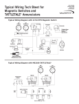
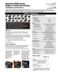
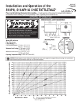
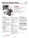
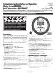
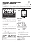
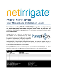
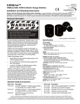
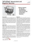
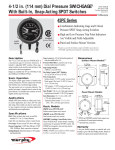
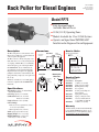
Rack Puller for Diesel Engines
RP-95028B/N
Revised 09-07
Catalog Section 40
(00-02-0106)
Model RP75
■
■
■
■
Description
The RP75 rack puller is a semi-automatic device
that provides a pulling force to initiate shutdown
of diesel engines and equipment.
The RP75 connects to the injection pump or air
intake shut-off lever via a cable (chain optional).
A coil spring, within the RP75, is reset manually
and is held in place by an electromagnet. When
the SWICHGAGE® detects a malfunction, the
electromagnetic circuit is interrupted through a
Magnetic Switch–releasing the coil spring thus
pulling the cable/chain to actuate shutdown. The
spring, when fully compressed, exerts a pull of 30
lbf (133 N).
The RP75 is available for 12 or 24 VDC applications and is compatible with all SWICHGAGE®
instruments.
Specifications
Operating Force: 30 lbf (133 N) maximum,
10 lbf (44 N) minimum.
Coil Voltage: Specify 12 or 24 VDC.
Coil Resistance: RP75-12: 32.2 ohms.
RP75-24: 129.8 ohms.
Length of Travel: 1-7/8 in. (48 mm).
Control Linkage
• Cable: 4ft. (1.22 m); Optional 8 ft. (2.43 m)
or 12 ft. (3.65 m) available.
• Chain (optional): 30 in. (762 mm).
NOTE: Specify options when ordering.
Shipping Weight: 5 lbs 3 oz. (2.4 kg).
Shipping Dimensions: 9-1/4 x 8-1/4 x
5-1/4 in. (235 x 210 x 133 mm).
Pulls Injection Pump or
Air Intake Shut-off Lever
30 lbf (133 N) Operating Force
Models Available for 12 or 24 Volt Systems
Operates on Signal from SWICHGAGE®
Installed on the Engine or Driven Equipment
Dimensions
How to Order
Side View
Wiring
Terminals
Reset Knob
and Stem
Specify model number.
RP75 – ____ – ____
Voltage
12 = 12 VDC
24 = 24 VDC
3-1/4 in.
(83 mm)
Calibration
Blank = 4 ft. (1.2 m) cable
8 = 8 ft. (2.4 m) cable
12 = 12 ft. (3.7 m) cable
C = Chain 30 in. (762 mm)
5-1/2 in.
(140 mm)
10-1/4 in.
(260 mm)
Rear View
Mounting Hole
Dimensions
Mounting
Studs
1/4-20
(4 places)
3-3/4 in.
(95 mm)
2-3/8 in.
(60 mm)
1-1/4 in.
(32 mm)
Service Parts
Specify part number.
Part Number Description
40-00-0021
12 VDC core assembly
40-00-0044
Shaft solenoid assembly
40-01-0050
Bushing shaft assembly
40-01-0053
Case repair kit
40-01-0054
Cocking rod, bushing and
knob repair kit
40-05-0136
Spring, main actuating
40-05-0149
Spring, cocking rod return
80-04-1030
2 Screws, machined #10-24
x 3/8 pan HD steel CAD II
40-00-0024
24 VDC core assembly
Warranty
A limited warranty on materials and workmanship
is given with this FW Murphy product. A copy of
the warranty may be viewed or printed by going to
www.fwmurphy.com/support/warranty.htm
Installation Instructions
✔
✔
✔
✔
Time Delay On Start
Magnetic Switch Energized to Run
WA R N I N G
Before beginning installation of this Murphy product:
Disconnect ALL electrical power to the machine.
Make sure the machine CANNOT operate during installation.
Follow all safety warnings of the machine manufacturer.
Read and follow all installation instructions.
761APH
117PH
C
S
B
G N.O. N.C. S
Battery
B
Battery
SWICHGAGE®
RP75
SWICHGAGE®
RP75
Mounting
Magnetic Switch Energized to Run
Wiring
Terminals
Reset Knob
and Stem
Cable
Attaching Nut
Outer Cable
Securing Nut
518PH
G
N.C. SW1 SW2 B
Battery
Figure 3
Push to Latch
“S” Hook
Lockwashers
(4 required)
1/4-20 Nut
(4 required)
Mounting
Bracket
SWICHGAGE®
Chain
RP75
Figure 1
Installing Cable or Chain
1. Mount the RP75 using a mounting bracket as illustrated in
1. To install the control linkage (cable or chain), apply voltage to
Figure 1 (see page 1 of this bulletin for mounting hole dimensions.). If installing the RP75 to an engine compartment firewall, go to Step 2.
Firewall
2. If installing the RP75 to an engine
Allenhead
Screw
compartment firewall, drill a 37/64
Reset
Stem
in. (15 mm) diameter hole in the
firewall (see Figure 2).
the RP75. Push in the reset knob. If installing the cable, insert
the cable attaching nut into the RP75 and tighten snugly (see
Figure 1). DO NOT OVERTIGHTEN or threads may strip.
Attach and tighten outer cable securing nut. If installing the
chain, attach the “S” hook to the RP75 (see Figure 1).
2. Attach the other end of the cable or chain to the injection pump
or air intake shut-off lever so it moves freely without sharp
bends and without binding.
Mounting
Nut
Reset
Knob
WARNING: The
firewall must be capable of withstanding the
push and pull force of the RP75.
Figure 2
3. Remove the reset knob on the RP75 by loosening the allenhead
screw on the knob.
4. Remove the mounting nut and insert the RP75 reset stem
through the hole from the back of the firewall.
5. Replace the mounting nut and tighten. Reinstall the reset knob.
Typical Wiring Diagrams
Wire the RP75 appropriately (see Figure 3). NOTE: RP75 is voltage
rated; do not apply 24 VDC to 12 VDC model and vice versa. Also,
the 117PH Magnetic Switch is rated for both 12 and 24 VDC circuits
but voltage must be specified when ordering the 518PH or 761APH
Magnetic Switches.
Operation Test
NOTE: Some method must be provided to disconnect (lockout) all
normally closed SWICHGAGE® circuits when starting (such as
through the appropriate Magnetic Switch).
1. Reset magnetic switch.
2. Push in RP75 reset stem until coil latches the trip mechanism.
3. Start engine and observe that all locked out contacts clear.
4. With engine running, ground SWICHGAGE® contact. The
Magnetic Switch will trip thus removing voltage to RP75. The
engine should shutdown immediately. If the engine does shutdown, adjust control linkage (cable or chain) to ensure that shutoff lever travels the full length in both directions.
CAUTION: Shut-off lever should not pull hard
against the stop in the “off” position.
FW MURPHY
CONTROL SYSTEMS & SERVICES DIVISION
COMPUTRONIC CONTROLS, LTD
P.O. Box 470248
Tulsa, Oklahoma 74147 USA
+1 918 317 4100 Fax: +1 918 317 4266
E-mail: [email protected]
P.O. Box 1819
Rosenberg, Texas 77471 USA
Phone: +1 281 633 4500 Fax: +1 281 633 4588
E-mail: [email protected]
INDUSTRIAL PANEL DIVISION
FRANK W. MURPHY, LTD
41 - 43 Railway Terrace Nechells
Birmingham B7 5NG UK
Phone: +44 121 327 8500 Fax: +44 121 327 8501
E-mail: [email protected]
Web site: www.computroniccontrols.com
Fax: +1 918 317 4124
E-mail: [email protected]
Church Rd Laverstock
Salisbury SP1 1QZ UK
Phone: +44 172 241 0055 Fax: +44 172 241 0088
E-mail: [email protected]
Web site: www.fwmurphy.co.uk
MURPHY POWER IGNITION
Web site: www.murphy-pi.com
www.
fwmurphy .com
FW MURPHY INSTRUMENTS (HANGZHOU) CO. LTD
77 23rd Street
Hangzhou Economic & Technological Development Area
Hangzhou, Zhejiang 310018 China
Phone: +86 571 8788 6060 Fax: +86 571 8684 8878
Printed in U.S.A.
RP-95028B/N page 2 of 2