1
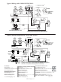
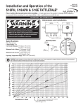
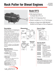
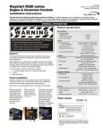
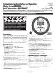
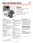
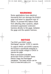
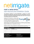
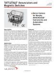
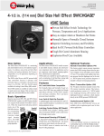
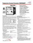
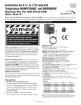
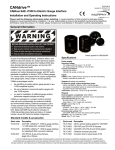
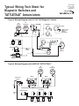
WIR-97020B
Revised 10-06
Section 25
(00-02-0257)
Typical Wiring Tech Sheet for
Magnetic Switches and
TATTLETALE® Annunciators
Typical Wiring Diagram with 117/117PH Magnetic Switch
20T
Temperature
20P
Pressure
117/117PH
Hourmeter
+ _
B+
Tachometer
SIG GRD
C
S
To Magnetic Sensor,
Alternator “Tach”
Terminal, or
Signal Generator
B
+ _
PB128S Stop Switch
Voltmeter
+ _
+ _
Battery
Ammeter
Ignition coil
Distributor
ST BAT
IGN
Fuel Valve
ACC
Energized
to Run
S
Start Switch
B
Alternator
Starter
Rack Pull Solenoid
(RP2300 Series shown)
Typical Wiring Diagram with MS2100 TATTLETALE®
20P
Pressure
20T
Temperature
MS2100
MS2100
Typical Power
Adaptor
6 1
G
A
A
2
3
4 5
6 1
S
Ignition Generator
B+
Exciter
Spark Plugs
“Kill”
Wire
Ignition Coils
WIR-97020B page 1 of 2
2
3
4 5
Typical Wiring with 518PH TATTLETALE®
CLOSEDLOOP™ Wiring*
518PH
20P-F
Pressure
20T-F
Temperature
Hourmeter
+ _
R
G NO
NC
Tachometer
SIG GRD
SW1
SW2 B
**
To Magnetic Sensor,
Alternator “Tach”
Terminal, or
Signal Generator
+ _
Jumper*
PB128S Stop Switch
B+
Voltmeter
+ _
Ignition coil
Distributor
+ _
Battery
B+
Ammeter
Fuel Valve
Exciter
ST BAT
IGN
Energized
to Run
ACC
S
Start Switch
B
Alternator
Starter
Rack Pull Solenoid (RP2300 Series shown)
*Jumper is to be removed when connecting a CLOSEDLOOP™ circuit.
**Normally Opened terminal is available on the 518APH & 518E models.
Typical Wiring Diagram with 760A and 761APH
760A/761APH
20P
Pressure
20T
Temperature
Hourmeter
TD
+ _
NOTE 1
B+
Tachometer
SIG GRD
G
NO
NC
S
To Magnetic Sensor,
Alternator “Tach”
Terminal, or
Signal Generator
B
+ _
PB128S Stop Switch
Voltmeter
Ignition
Coil
Distributor
Flyback
Diode
Fuel
Valve
Rack Pull
Solenoid
(RP2300
Series shown)
R
+ _
Normally Open
Relay with
Flyback Diode
Ammeter
Energized
to Run
Battery
B+
Exciter
ST BAT
IGN
ACC
S
Start Switch
Flyback
Diode
Flyback
Diode
+ _
B
Alternator
Starter
NOTE 1: With terminal “G” grounded, the time delay operates only on start; after the initial
time delay, the shut-down circuit is operated immediately when SWICHGAGE® contact operates.
With terminal “G” not grounded, the time delay operates both on start and stop.
FW MURPHY
CONTROL SYSTEMS & SERVICES DIVISION
COMPUTRONIC CONTROLS, LTD
P.O. Box 470248
Tulsa, Oklahoma 74147 USA
+1.918.317.4100 Fax: +1.918.317.4266
E-mail: [email protected]
P.O. Box 1819
Rosenberg, Texas 77471 USA
Phone: 281.633.4500 Fax: 281.633.4588
E-mail: [email protected]
Web site: www.fwmurphy.com
41 - 43 Railway Terrace Nechells
Birmingham B7 5NG UK
Phone: +44 121 327 8500 Fax: +44 121 327 8501
E-mail: [email protected]
Web site: www.computroniccontrols.com
FRANK W. MURPHY, LTD
FW MURPHY INSTRUMENTS (HANGZHOU) CO. LTD
Church Rd Laverstock
Salisbury SP1 1QZ UK
Phone: +44 1722 410055 Fax: +44 1722 410088
E-mail: [email protected]
Web site: www.fwmurphy.co.uk
77 23rd Street
Hangzhou Economic & Technological Development Area
Hangzhou, Zhejiang, 310018, China
Phone: +86 571 8788 6060 Fax: +86 571 8684 8878
INDUSTRIAL PANEL DIVISION
Fax: 918.317.4124
E-mail: [email protected]
MURPHY POWER IGNITION
Web site: www.murphy-pi.com
www.fwmurphy.com
WIR-97020B page 2 of 2
Printed in U.S.A.