1
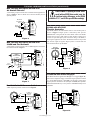
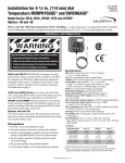
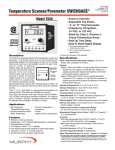
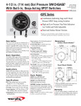
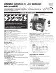
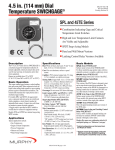
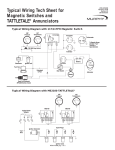
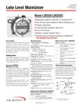
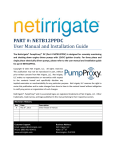
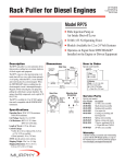
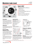
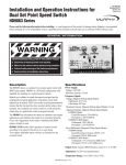
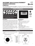
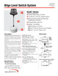
SS-97028N
Revised 05-04
Section 20
Installation and Operation Instructions for
SELECTRONIC® Speed Switches
SS300 Series
00-02-0286
Please read the following information before installing. A visual inspection of this product for damage during shipping is recommended before mounting. It is your responsibility to have a qualified person install this unit and make sure it conforms to NEC
and local codes.
GENERAL INFORMATION
SS300-AD
WARNING
SPEED SWITCH
1
2
PICKUP
3
ENERGIZE
4 INPUT
BEFORE BEGINNING INSTALLATION OF THIS MURPHY PRODUCT
✔
✔
✔
✔
5 -BATT
SPEED
ADJ.
6 +BATT
Disconnect all electrical power to the machine.
Make sure the machine cannot operate during installation.
Follow all safety warnings of the machine manufacturer.
Read and follow all installation instructions.
7 GND. FOR
T/D
8 POS. TO
DE-ENERGIZE
LATCH
Description
Specifications
The SS300 Series are single set point speed switches with SPDT relay dry contact
output. The trip point is set by a potentiometer. An LED indicates when the signal
source is present. A second LED turns on when the trip point is reached. See Table 1
for available models and requirements. An optional time delay is on board to delay
operation of the relay for 2-6 seconds after the set point has been reached.
Power Requirements:
12 VDC (9-16 VDC).
24 VDC (18-30 VDC).
Frequency Signal: Voltage (all models):
• Minimum Input Voltage Signal: 4.5 Vrms.
• Maximum Input Voltage Signal: 50 Vrms.
The SS300 Series speed switch is intended for installation within a weatherproof
enclosure to protect it from rain, dust, etc.
Overspeed Shutdown
Maximum Current
12V
24V
Pull In
46 mA
46 mA
Pickup only
10.5 mA
16 mA
The SS300 Series shuts down the engine if RPM exceeds the pre-set limit.
Speed Sensitive Pull-in/Drop-out
Engage or disengage PTO’s, 4-wheel drives, other switch points, etc. according
to speed of engine being monitored.
Frequency Range in Hz
Engine and Transmission Alarm/Shutdowns
Oil pressure in some engines and transmissions varies widely between running
and idle speeds. The SS300 Series can select between two pressure switch set
points according to speed of the engine or transmission and thus give maximum
protection to the equipment while at operating RPM and eliminate nuisance
alarms when at idle.
Adjustable Differential Model
The (“AD”) can be adjusted to change the speed range over which the pull-in and
drop-out differential of the relay will operate. A typical application is to insure
that engine speed is above a minimum RPM before applying a load but allows a
drop in speed of several hundred RPM without disconnecting the load.
Table 1: Models Available and Input Signal
Model Number
Distributor Magnetic
Pickup
Ignition
✗
SS300 (std. model)
SS300-LF (low frequency)
✗
✗
Voltage
12
24
✗
✗
✗
✗
✗
✗
✗
✗
✗
✗
✗
SS300-AD (adjustable differential)
SS300-AD-LF (low frq. & Adjst. diff.)
Alternator
Model Number
25-2000
SS300-LF
SS300-AD-LF
625-9000
SS300-AD
SS300
Reset Differential Magnetic Pickup Signal Models:
• “Standard Models: 2 Hz Differential.
• “AD” Models (Adjustable Differential): 650-8900 Hz Adjustable
Reset Differential Alternator Models:
• “LF” Models (Low Frequency): 2 Hz Differential
• “AD-LF” Models (Adjustable Differential Low Frequency):
50-1900 Hz Adjustable.
Output: Relay contact, SPDT, resistive load, 6 A, 30 VDC.
Time Delay: When terminal 7 is grounded, the relay operation is delayed for
2-6 seconds after rpm set point is reached.
Adjustment: 20–turn potentiometer(s).
Temperature Range: -4° to 185°F (-20° to 85°C).
Relative Humidity: 0 to 95% Non-condensing.
Case: Black, ABS plastic.
SS-97028N page 1 of 4
MOUNTING DIMENSIONS
CAUTION: THE SS300 SERIES MODELS ARE INTENDED FOR INSTALLATION WITHIN A WEATHERPROOF ENCLOSURE.
1-1/32 in.
(26 mm)
The SS300 Series models can be mounted to a flat surface within
the panel using two #8 screws. Mounting screws are not supplied.
3 in.
(76 mm)
2-1/2 in.
(64 mm)
SS300 Series
(all models)
2 in.
(51 mm)
3/16 in. (5 mm)
dia. two places
2-1/16 in.
(52 mm)
TYPICAL WIRING INSTALLATION
CAUTION: BEFORE PERFORMING THE WIRING OPERATION TURN THE POWER SOURCE
OFF AND STOP YOUR ENGINE.
Frequency/RPM Input Source
Connect the SS300 Series speed switch to the appropriate frequency/RPM
input source. See Figures 1 thru 3.
SPEED
1
2
Magnetic Pickup
CAUTION: If replacing an SS100 Series
model with an SS300 Series model, note the
significant wiring differences on the SS300
terminals: 5, 6, 7, and 8. Wire your SS300 accordingly.
3
4 INPUT
5 – BATT.
6 + BATT.
-- +
Battery
7 GND. FOR
T/D
8 POS. TO
LATCH
Ignition
Switch
SS300
Latching Overspeed with Fuel Solenoid
A latching overspeed switch with fuel solenoid application is shown in
Figures 4 and 5. Ignition switch must be turned off to unlatch.
Figure 1: Magnetic Pickup Input
SPEED
SPEED
To Alternator
Tach. Terminal
1
Fuel
Solenoid
2
3
1
4 INPUT
2
3
4 INPUT
Speed
Signal
5 – BATT.
6 + BATT.
5 – BATT.
6 + BATT.
-- +
Battery
Ignition
Switch
-- +
Battery
7 GND. FOR
T/D
8 POS. TO
LATCH
Ignition
Switch
7 GND. FOR
T/D
8 POS. TO
LATCH
SS300
Figure 4: Energize to Run Solenoid
SS300
Figure 2: Alternator Tach., Input
Energize to stop
Solenoid
SPEED
--
+
Coil
2
2
3
3
4 INPUT
4 INPUT
Speed
Signal
5 – BATT.
5 – BATT.
6 + BATT.
6 + BATT.
-- +
Battery
Ignition
Switch
SPEED
1
1
7 GND. FOR
T/D
8 POS. TO
LATCH
-- +
Battery
SS300
Ignition
Switch
7 GND. FOR
T/D
8 POS. TO
LATCH
SS300
Figure 5: Energize to Stop Solenoid
Figure 3: Distributor Ignition Input
SS-97028N page 2 of 4
TYPICAL WIRING INSTALLATION (continued)
Non Latching Overspeed Switch with
Air Shutoff Solenoid
A non-latching overspeed switch with air shutoff solenoid application is
shown in Figure 6. The air shutoff device must be manually reset to
open/run position.
Air Shutoff
Energized to
Close
CAUTION: If replacing an SS100 Series
model with an SS300 Series model, note the
significant wiring differences on the SS300
terminals: 5, 6, 7, and 8. Wire your SS300 accordingly.
SPEED
1
2
3
Speed
Signal
4 INPUT
SS300 with AT-67207
Throttle Controller
5 – BATT.
6 + BATT.
7 GND. FOR
T/D
8 POS. TO
LATCH
-- +
Battery
The SS300 with the AT-67207 throttle control is used to limit speed as
shown in Figure 9. Engine speed is controlled by OPL pressure
SWICHGAGE® setting and the AT-67207 throttle control. The throttle
control moves as long as OPL contact is made. If OPL is calling for an
increase in speed and engine speed exceeds the setting of the SS300, a
slow signal is applied to AT-67207. The throttle control will stop if both
fast and slow signals are applied. Engine speed at a constant load will
not exceed the limit set by the SS300.
SS300
Figure 6
Non Latching Overspeed Switch with
518PH and Fuel Solenoid
A non-latching overspeed switch with an 518PH magnetic switch and a
fuel solenoid is shown in Figure 7.
Pressure
SWICHGAGE®
AT-67207
Battery
Slow
Fast
SPEED
SPEED
1
3
4 INPUT
3
5 – BATT.
4 INPUT
Speed
Signal
B
SW2
SW1
G
2
2
518PH
TATTLETALE®
NC
1
Speed
Signal
5 – BATT.
6 + BATT.
7 GND. FOR
T/D
8 POS. TO
LATCH
6 + BATT.
7 GND. FOR
T/D
8 POS. TO
LATCH
Fuel
Solenoid
-- +
Battery
SS300
SS300
Fuse
Figure 9
-- +
Battery
SS300-AD with Clutch Engager
Oil
Pressure
The SS300-AD can be applied with a Murphy CO-3 engager (Figure 10).
The circuit is designed to engage a clutch after engine speed has increased
to a preset RPM (Example: 1200 RPM), and disengage clutch when
engine speed has decreased to idle (Example: 600 RPM). The adjustable
differential SS300-AD relay is set to pull in at 1200 RPM and drop out at
600 RPM.
Water
Temperature
Figure 7
Dual Set Point Oil Pressure Switch
A dual set point oil pressure switch is shown in Figure 8.
SPEED
To alarm or
shutdown
Circuit
N.C.
C
SPEED
1
2
N.O.
1
CO-3
3
5
4
Common 3
Disengage 2
Engage 1
2
3
4 INPUT
5 – BATT.
6 + BATT.
Speed
Signal
4 INPUT
5 – BATT.
Speed Signal
-- +
Battery
On - Off
Switch
6 + BATT.
7 GND. FOR
T/D
8 POS. TO
LATCH
SS300
Figure 8
SS-97028N page 3 of 4
-- +
Battery
7 GND. FOR
T/D
8 POS. TO
LATCH
SS300
Figure 10
SPEED SETTING ADJUSTMENT
For Models SS300 and SS300-LF
For Models SS300-AD and SS300-AD-LF
NOTE: The adjustment control(s) is a 20-turn potentiometer(s) and
have no stops when the extreme settings are reached. Always turn a
full 20 turns.
1. Make sure the PICKUP LED light is “ON”. The PICKUP LED will be
flashing for low frequency (under 30 Hz) and will remain “ON” for a
high frequency.
1. Make sure the PICKUP LED light is “ON”. The PICKUP LED will
be flashing for a low frequency (under 30 Hz) and will remain “ON”
for a higher frequency.
2. Turn the SPEED ADJUST pot fully clockwise 20 turns (Figure 14).
2. Turn the SPEED ADJUST pot fully clockwise 20 turns (Figure 13).
3. Run the engine at the desired RPM and adjust the SPEED ADJUST pot
counterclockwise until the ENERGIZE LED comes “ON” and the
relay has transferred (Figure 13).
3. Turn the DE-ENERGIZE pot fully counterclockwise 20 turns.
4. Run the engine at the desired RPM and adjust the SPEED ADJUST pot
counterclockwise until the ENERGIZE LED comes “ON” and relay
has transferred.
5. Reduce the engine speed to the desired drop out point.
6. Adjust the DE-ENERGIZE pot clockwise until the ENERGIZE LED
goes “OFF” and the relay has dropped out (Figure 14).
P
PICKU
20 turn
potentiometers
SPEED
ADJ.
LED
Lights
GIZE
ENER
IZE
NERG
DE-E
D
SPEE
Figure 14
Figure 13
Warranty
A limited warranty on materials and workmanship is given with this FW Murphy product.
A copy of the warranty may be viewed or printed by going to www.fwmurphy.com/support/warranty.htm
GI
D
MURPHY SWITCH OF CALIFORNIA
41343 12th Street West
Palmdale, California 93551-1442; USA
+1 661 272 4700 fax +1 661 947 7570
e-mail [email protected]
www.murphyswitch.com
MACQUARRIE CORPORATION
1620 Hume Highway
Campbellfield, Vic 3061; Australia
+61 3 9358 5555 fax +61 3 9358 5558
e-mail [email protected]
E
MURPHY DE MEXICO, S.A. DE C.V.
Blvd. Antonio Rocha Cordero 300, Fracción del Aguaje
San Luis Potosí, S.L.P.; México 78384
+52 444 8206264 fax +52 444 8206336
Villahermosa Office +52 993 3162117
e-mail [email protected]
www.murphymex.com.mx
FRANK W. MURPHY, LTD.
Church Rd.; Laverstock, Salisbury SP1 1QZ; U.K.
+44 1722 410055 fax +44 1722 410088
e-mail [email protected]
www.fwmurphy.co.uk
RE
FW Murphy
P.O. Box 470248
Tulsa, Oklahoma 74147 USA
+1 918 317 4100
fax +1 918 317 4266
e-mail [email protected]
www.fwmurphy.com
CONTROL SYSTEMS & SERVICES DIVISION
P.O. Box 1819; Rosenberg, Texas 77471; USA
+1 281 633 4500 fax +1 281 633 4588
e-mail [email protected]
STER
USA–ISO 9001:2000 FM 28221
UK–ISO 9001:2000 FM 29422
In order to consistently bring you the highest quality, full featured products, we reserve the right to change our specifications and designs at any time.
Printed in U.S.A.
SS-97028N page 4 of 4