1
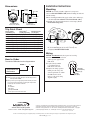
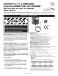
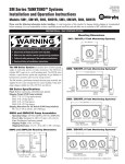
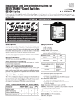
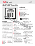
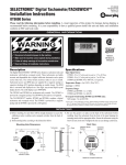
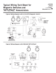
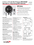
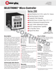
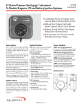
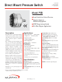
Direct Mount Pressure Switch
PSB-9104B
Revised 03-06
Catalog Section 05
(00-02-0031)
Model PSB
■ Limit Switch for Critical Pressure
■ Operate Alarms or
**
Shutdown Equipment
■ SPDT Snap-Acting Switch
■ Fits Most Engine Applications
Description
Applications
The PSB switch is a direct mount switch for
critical pressure points. It has one limit
contact that can be used to activate an alarm,
actuate indicator lights or shutdown
equipment.
• Engine Lubrication • Water pumps
• Compressors • Oil field systems
• Irrigation systems
• Construction Equipment
• Mobile Equipment
• Marine engines • Generators
The construction of this instrument is the
same as our time-proven Swichgage ®
instrument. A precision machined brass
mounting plate and port captures a high
quality stamped beryllium copper
diaphragm. The single-pole, double-throw
(SPDT) snap-switch is operated directly
from the diaphragm for quick acting and
positive switching. Trip point is factory
preset according to your specifications.
Housing is weather sealed to prevent entry of
moisture, dust, etc. A glass-filled nylon
terminal block with quick screw terminal
connections gives the PSB switch a real
advantage in industrial engine applications.
The PSB is ideal when reading is not desired,
but pressure is critical to operational
efficiency.
Intended for use in general purpose nonclassified areas.
Features
• Fits all engine applications
• SPDT snap-switch
• Activates indicator lights, alarms, or shut
down equipment
• Time-proven SWICHGAGE® construction
• Easy wiring terminal block
• Steel housing specially coated to resist
corrosion
• Factory preset to your specifications
Specifications
Housing: Plated steel.
Pressure Connection: 1/8-27 NPT, Brass.
Diaphragm: Formed beryllium copper (heat
treated).
Pulsation Dampener: Brass (it is removable
for cleaning).
**Products covered by this bulletin comply with EMC Council directive 89/336/EEC
regarding electromagnetic compatibility except as noted.
PSB-9104B page 1 of 2
Terminal Block: Three #4-40 screws.
Accuracy: Trip point: ±3% of full scale.
Switch reset differential: ±7% of full scale.
Repeatability: ±1% of full scale.
Contact Rating: SPDT 3 A @ 30 VDC
inductive.
Maximum Pressure: See Trip Point Chart
on reverse side.
Temperature Range:
Ambient= -40°F (-40°C) thru 150°F (66°C).
Process= -40°F (-40°C) thru 250°F (121°C).
Factory Trip Point Setting: See Trip Point
Chart (on back).
Pressure Range: Specify from 0-400 psi (02.76 MPa) [0- 27.58 bar]. See Trip Point
Chart on reverse side.
Contact: Operates on rising or falling
pressure (specify).
Shipping Weight: 8 oz. (0.25 kgs).
Shipping Dimensions: 3 x 2-3/4 x 2-3/4 in.
(76 x 70 x 70 mm).
NOTE: No customer replacement parts.
Dimensions
Installation Instructions
Mounting
2-9/16 in.
(65 mm)
2-1/4 in.
(57 mm)
1/8-27 NPT
NO C NC
CAUTION: Use wrench on shank to tighten or loosen pressure
connection. DO NOT TWIST CASE, which will damage the unit and
void the warranty.
1. Before installing the PSB switch, apply sealant, such as Teflon tape,
to the threads (be sure sealant does not block the inlet orifice).
2. The PSB can be mounted in horizontal or vertical angles (do not
mount switch facing down).
2-1/32 in. Dia.
(52 mm)
1/2 in. (13 mm)
Square wrench flats
Slot head terminal
screws (4-40, UNC-2A)
Factory setting*
psi (kPa) [bar] Falling
Maximum pressure
psi (kPa) [bar]
0-15 (0-103) [0-1.03]
0-30 (0-207) [0-2.07]
0-50 (0-345) [0-3.45]
0-75 (0-517) [0-5.17]
0-100 (0-689) [0-6.89]
0-150 (0-1.03) [0-10.34]
0-200 (0-1.38) [0-13.79]
0-300 (0-2.07) [0-20.70]
0-400 (0-2.76) [0-27.60]
3 (21) [.21]
7 (48) [.48]
10 (69) [.69]
15 (103) [1.03]
20 (138) [1.38]
30 (207) [2.07]
50 (345) [3.45]
75 (517) [5.17]
150 (1.03) [10.34]
30 (207) [2.07]
60 (414) [4.14]
100 (0-689) [0-6.89]
150 (0-1.03) [0-10.34]
200 (0-1.38) [0-13.79]
300 (0-2.07) [0-20.70]
400 (0-2.76) [0-27.60]
500 (3.45) [34.50]
500 (3.45) [34.50]
*These points will be used if switch trip point is not specified.
n
gA
gle
WRONG
UP
3. Locate the unit in place and secure it by tightening
the 1/8-27 NPT fitting into the desired location (do not
overtighten). DO NOT TWIST CASE.
Wiring
How to Order
To order the PSB model use the diagram below.
PSB –
u
in
nt
M
Ranges available
psi (kPa/MPa) [bar]
o
Trip Point Chart
–
Pressure Range
Specify maximum value
from chart above.
Switch Trip Point †
F = Factory set to trip on falling. Specify “F” and the set point value.
Example: PSB-100-F20.
R = Factory set to trip on rising, Specify “R” and the set point value.
For units of measure other than psi, specify the set point value
followed by unit of measure as follows:
B = Bar
K = kPa/MPa
M = kg/cm2
Example: PSB-7B-2B
CAUTION: DISCONNECT Electrical power before wiring.
1. Switch contacts (below) are shown
with no pressure applied to the
PSB switch.
2. A spade (forked) terminal
is recommended for all
PSB switch connections.
Normally
3. Complete the wiring operation
Closed (N.C.)
making sure the voltage and
Common (C)
current requirements are within
Normally
the PSB switch electrical
Open (N.O.)
rating (see the typical wiring
diagram at right).
†Switch set point value will be stated on label.
www.fwmurphy.com
918.317.4100 Email: [email protected]
In order to consistently bring you the highest quality, full featured products, we reserve the right to change our
specifications and designs at any time. MURPHY, the Murphy logo are registered and/or common law
trademarks of Murphy Industries, Inc. This document, including textual matter and illustrations, is copyright
protected by Murphy Industries, Inc., with all rights reserved. (c) 2006 Murphy Industries, Inc.
Printed in U.S.A. 0591124M
In order to consistently bring you the highest quality, full featured products, we reserve the right to change our specifications and designs at any time.
PSB-9104B page 2 of 2