1
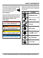
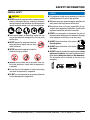
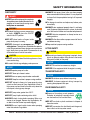
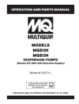
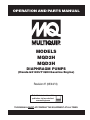
OPERATION AND PARTS MANUAL MODELS MQD2H MQD3H DIAPHRAGM PUMPS (Honda GX120UT1QX2 Gasoline Engine) Revision #7 (05/24/13) To find the latest revision of this publication, visit our website at: www.multiquip.com THIS MANUAL MUST ACCOMPANY THE EQUIPMENT AT ALL TIMES. PROPOSITION 65 WARNING PAGE 2 — MQD2H/3H DIAPHRAGM PUMPS — OPERATION AND PARTS MANUAL — REV. #7 (05/24/13) NOTES MQD2H/3H DIAPHRAGM PUMPS — OPERATION AND PARTS MANUAL — REV. #7 (05/24/13) — PAGE 3 TABLE OF CONTENTS MQD2H/D3H Gasoline Powered Diaphragm Pumps Proposition 65 Warning ............................................. 2 Table of Contents ...................................................... 4 Parts Ordering Procedures ....................................... 5 Safety Information .................................................. 6-9 Specifications ...........................................................10 Dimensions ..............................................................11 General Information .................................................12 Components.............................................................13 Basic Engine ............................................................14 Inspection .................................................................15 Set-up ................................................................ 16-17 Operation ........................................................... 18-19 Maintenance ...................................................... 20-25 Preparation for Long-Term Storage .........................26 Troubleshooting ................................................. 27-29 Explanation Of Code In Remarks Column ...............30 Suggested Spare Parts ............................................31 HONDA GX120UT1QX2 Engine Air Cleaner Assembly......................................... 46-47 Camshaft Assembly ........................................... 48-49 Carburetor Assembly ......................................... 50-51 Control Assembly ............................................... 52-53 Crankcase Cover Assembly ............................... 54-55 Crankshaft Assembly ......................................... 56-57 Cylinder Barrel Assembly ................................... 58-59 Cylinder Head Assembly .................................... 60-61 Fan Cover Assembly .......................................... 62-63 Flywheel Assembly ............................................ 64-65 Fuel Tank Assembly ........................................... 66-67 Ignition Coil Assembly ........................................ 68-69 Muffler Assembly ............................................... 70-71 Piston Assembly ................................................. 72-73 Recoil Starter Assembly..................................... 74-75 Gasket Kit Assembly .......................................... 76-77 Labels ................................................................ 78-79 Terms and Condition Of Sale — Parts .................... 80 NOTICE Component Drawings Nameplate and Decals Assy. ............................. 32-33 Waterbox and Flap Valve Assy. (2-inch) ............. 34-35 Pump Assy. (2-inch) ........................................... 36-37 Handle, Engine and Wheel Assy. (2-inch) .......... 38-39 Waterbox and Flat Valve Assy. (3-inch) .............. 40-41 Pump Assy. (3-inch) ........................................... 42-43 Handle, Engine and Wheel Assy. (3-inch) .......... 44-45 Specification and part number are subject to change without notice. PAGE 4 — MQD2H/3H DIAPHRAGM PUMPS — OPERATION AND PARTS MANUAL — REV. #7 (05/24/13) www.multiquip.com PARTS ORDERING PROCEDURES Ordering parts has never been easier! Choose from three easy options: Order via Internet (Dealers Only): Best Deal! Effective: January 1st, 2006 If you have an MQ Account, to obtain a Username and Password, E-mail us at: parts@multiquip. com. Order parts on-line using Multiquip’s SmartEquip website! ■ View Parts Diagrams ■ Order Parts ■ Print Specification Information To obtain an MQ Account, contact your District Sales Manager for more information. Use the internet and qualify for a 5% Discount on Standard orders for all orders which include complete part numbers.* Goto www.multiquip.com and click on Order Parts to log in and save! Note: Discounts Are Subject To Change Order via Fax (Dealers Only): All customers are welcome to order parts via Fax. Domestic (US) Customers dial: 1-800-6-PARTS-7 (800-672-7877) Fax your order in and qualify for a 2% Discount on Standard orders for all orders which include complete part numbers.* Note: Discounts Are Subject To Change Order via Phone: Domestic (US) Dealers Call: 1-800-427-1244 Non-Dealer Customers: Contact your local Multiquip Dealer for parts or call 800-427-1244 for help in locating a dealer near you. International Customers should contact their local Multiquip Representatives for Parts Ordering information. When ordering parts, please supply: ❒ ❒ ❒ ❒ ❒ ❒ Dealer Account Number Dealer Name and Address Shipping Address (if different than billing address) Return Fax Number Applicable Model Number Quantity, Part Number and Description of Each Part ❒ Specify Preferred Method of Shipment: ✓ UPS/Fed Ex ✓ DHL ■ Priority One ✓ Truck ■ Ground ■ Next Day ■ Second/Third Day NOTICE All orders are treated as Standard Orders and will ship the same day if received prior to 3PM PST. WE ACCEPT ALL MAJOR CREDIT CARDS! MQD2H/3H DIAPHRAGM PUMPS — OPERATION AND PARTS MANUAL — REV. #7 (05/24/13) — PAGE 5 SAFETY INFORMATION Do not operate or service the equipment before reading the entire manual. Safety precautions should be followed at all times when operating this equipment. Failure to read and understand the safety messages and operating instructions could result in injury to yourself and others. Potential hazards associated with the operation of this equipment will be referenced with hazard symbols which may appear throughout this manual in conjunction with safety messages. SAFETY MESSAGES The four safety messages shown below will inform you about potential hazards that could injure you or others. The safety messages specifically address the level of exposure to the operator and are preceded by one of four words: DANGER, WARNING, CAUTION or NOTICE. SAFETY SYMBOLS DANGER Indicates a hazardous situation which, if not avoided, WILL result in DEATH or SERIOUS INJURY. WARNING Indicates a hazardous situation which, if not avoided, COULD result in DEATH or SERIOUS INJURY. CAUTION Indicates a hazardous situation which, if not avoided, COULD result in MINOR or MODERATE INJURY. NOTICE Addresses practices not related to personal injury. PAGE 6 — MQD2H/3H DIAPHRAGM PUMPS — OPERATION AND PARTS MANUAL — REV. #7 (05/24/13) SAFETY INFORMATION GENERAL SAFETY CAUTION NEVER operate this equipment without proper protective clothing, shatterproof glasses, respiratory protection, hearing protection, steel-toed boots and other protective devices required by the job or city and state regulations. Avoid wearing jewelry or loose fitting clothes that may snag on the controls or moving parts as this can cause serious injury. NEVER operate this equipment when not feeling well due to fatigue, illness or when under medication. NEVER operate this equipment under the influence of drugs or alcohol. NOTICE This equipment should only be operated by trained and qualified personnel 18 years of age and older. Whenever necessary, replace nameplate, operation and safety decals when they become difficult read. Manufacturer does not assume responsibility for any accident due to equipment modifications. Unauthorized equipment modification will void all warranties. NEVER use accessories or attachments that are not recommended by Multiquip for this equipment. Damage to the equipment and/or injury to user may result. ALWAYS know the location of the nearest fire extinguisher. ALWAYS know the location of the nearest first aid kit. ALWAYS know the location of the nearest phone or keep a phone on the job site. Also, know the phone numbers of the nearest ambulance, doctor and fire department. This information will be invaluable in the case of an emergency. ALWAYS clear the work area of any debris, tools, etc. that would constitute a hazard while the equipment is in operation. No one other than the operator is to be in the working area when the equipment is in operation. DO NOT use the equipment for any purpose other than its intended purposes or applications. MQD2H/3H DIAPHRAGM PUMPS — OPERATION AND PARTS MANUAL — REV. #7 (05/24/13) — PAGE 7 SAFETY INFORMATION PUMP SAFETY DANGER NEVER operate the equipment in an explosive atmosphere or near combustible materials. An explosion or fire could result causing severe bodily harm or even death. WARNING ALWAYS flush pump (clean) after use when pumping water concentrated with heavy debris. It is very important to always flush the pump before turning it off to prevent clogging. Fix damage to machine and replace any broken parts immediately. ALWAYS store equipment properly when it is not being used. Equipment should be stored in a clean, dry location out of the reach of children and unauthorized personnel. Accidental starting can cause severe injury or death. ALWAYS place the ON/OFF switch in the OFF position. NEVER lubricate components or attempt service on a running machine. DO NOT place hands or fingers inside pump when pump is running. ALWAYS allow the machine a proper amount of time to cool before servicing. NEVER disconnect any emergency or safety devices. These devices are intended for operator safety. Disconnection of these devices can cause severe injury, bodily harm or even death. Disconnection of any of these devices will void all warranties. Keep machine in proper running condition. CAUTION DO NOT restrict the flow of the discharge hose as it may cause overheating. Be careful of discharge whipping under pressure. NOTICE NEVER operate pump on its side. DO NOT allow up to freeze in water. NEVER leave an open pump chamber unattended. ALWAYS keep the machine in proper running condition. DO NOT attempt to thaw-out a frozen pump by using a torch or other source of flame. Application of heat in this manner may heat the oil in the seal cavity above the critical point, causing pump damage. DO NOT pump water greater than 104º F. DO NOT pump liquids containing acid or alkali. ALWAYS check strainer before pumping. Make sure strainer is not clogged. Remove any large objects, dirt or debris from the strainer to prevent clogging. ALWAYS use a large basket strainer when pumping water that contains large debris. LIFTING SAFETY CAUTION When raising or lowering of the pump is required, always attach an adequate rope or lifting device to the correct lifting point (handle) on the pump. NOTICE DO NOT lift machine to unnecessary heights. NEVER lift the equipment while the engine is running. TRANSPORTING SAFETY NOTICE ALWAYS shutdown pump before transporting. ALWAYS tie down equipment during transport by securing the equipment with rope. ENVIRONMENTAL SAFETY NOTICE Dispose of hazardous waste properly. Examples of potentially hazardous waste are used motor oil, fuel and fuel filters. DO NOT use food or plastic containers to dispose of hazardous waste. DO NOT pour waste, oil or fuel directly onto the ground, down a drain or into any water source. PAGE 8 — MQD2H/3H DIAPHRAGM PUMPS — OPERATION AND PARTS MANUAL — REV. #7 (05/24/13) NOTES MQD2H/3H DIAPHRAGM PUMPS — OPERATION AND PARTS MANUAL — REV. #7 (05/24/13) — PAGE 9 SPECIFICATIONS Table 1. Specifications (Pump) Pump Type MMQD2H Q-D2H Diaphragm DiaphragmPump Pump MMQD3H Q-D3H DDiaphragm iaphragm Pump Pump Suction & Discharge Size 2.00 in. (50.8 mm.) 3.00 in. (76.2 mm.) Maximum Pumping Capacity 3,000 gallons/hour (11,340 liters/hour) 5,400 gallons/hour (20,456 liters/hour) Max. Solids Diameter 1-1/2 in. (38.1 mm) 1-5/8 in (41.275 mm) Max Lift 26 ft. (7.92 meters) 26 ft. (7.92 meters) Max. Head 25 ft. (7.62 meters) 25 ft. (7.62 meters) 140 lbs. (63 Kg.) 160 lbs. (72 Kg.) Dry Net Weight Table 2. Specifications (Engine) Model HONDA GX120UT1QX2 Type Air-cooled 4 stroke, Single Cylinder, OHV, Horizontal Shaft Gasoline Engine Bore X Stroke 2.4 in. x 1.7 in. (60 mm x 42 mm) Displacement 119 cc (7.2 cu-in) Max Output Fuel Tank Capacity Fuel Lube Oil Capacity Speed Control Method Starting Method Dimension (L x W x H) Dry Net Weight 4.0 H.P./2,750 R.P.M. 0.66 US gal. (2.5 liters) Unleaded Automobile Gasoline .60 liters (0.63 qts) Centrifugal Fly-weight Type Recoil Start 11.7 x 13.4 x 12.5 in. (297 x 341 x 318 mm) 28.7 lbs (13 Kg.) PAGE 10 — MQD2H/3H DIAPHRAGM PUMPS — OPERATION AND PARTS MANUAL — REV. #7 (05/24/13) DIMENSIONS MQ-D2H/D3H — DIMENSIONS (PUMP) Figure 1. MQD2H/D3H Pump Dimensions Table 3. Dimensions MODEL A LENGTH B HEIGHT C WIDTH D DISCHARGE E SUCTION MQ-D2H MQD2H 39 in. (99.06 cm.) 27.53 in. (69.93 cm.) 25.68 in. (65.23 cm.) 7.34 in. (18.64 cm.) 5.62 in. (14.27 cm.) MQD3H M Q-D3H 41.5 in. (105.41 cm.) 22 in. (55.88 cm.) 30 in. (76.2 cm.) 6.2 in. (15.75 cm.) 6.3 in. (16 cm.) MQD2H/3H DIAPHRAGM PUMPS — OPERATION AND PARTS MANUAL — REV. #7 (05/24/13) — PAGE 11 MQ-D2H/D3HGENERAL — GENERAL INFORMATION INFORMATION APPLICATION The MQD2H and MQD3H diaphragm pumps are designed to be used for de-watering applications. The suction and discharge ports on the MQD2H use a 2-inch diameter opening, which allows the pump to pump at rate of approximately 3,000 gallons/hour (gph) or 11,340 liters/hour (lph). The suction and discharge ports on the MQD3H use a 3-inch diameter opening, which allows the pump to pump at rate of approximately 5,400 gallons/hour (gph) or 20,456 liters/hour (lph). Diaphragm pumps use a positive displacement design rather than centrifugal force to move water through the casing. This means the pump will deliver a specific amount of flow per stroke, revolution or cycle. These pumps are commonly referred to as mud hogs, mud hens and mud suckers. Their names reflect their popularity for use in applications where shallow depths and slurry water render centrifugal pumps ineffective. Elevation Higher elevations will effect the performance of the pump. Due to less atmospheric pressure at higher altitudes, pumps DO NOT have the priming ability that they have at sea level. This is due to the “thinner air” or lack of oxygen at higher altitudes. A general rule of thumb is that for every 1,000 feet of elevation above sea level a pump will lose one foot of priming ability. For example, in Flagstaff, Arizona where the elevation is approximately 7,000 feet, the pump would have a suction lift of only 18 feet rather than the 25 feet at sea level. Table 3 shows suction lift at various elevations. Table 4. Suction Lift at Various Elevations Altitude Feet (Meters) Suction Lift in Feet (Meters) Power Plant Sea Level 10.0 (3.048) 15.0 (4.572) 20.0 (6.096) 25.0 (7.620) These diaphragm pumps are powered by a 4.0 horsepower air cooled, 4-stroke, single cylinder HONDA GX120 gasoline engine that incorporates a low “Oil Alert Feature” . The drive shaft of the engine is coupled to an offset connecting rod that is coupled to a flexible diaphragm. The connecting rod alternately raises (expands) and lowers (contracts) the diaphragm at a rate of 60 cycles per minute at maximum engine RPM (2,750). 2,000 (610) 8.80 (2.680) 13.2 (4.023) 17.6 (5.364) 22.0 (6.705) 4,000 (1,219) 7.80 (2.377) 11.7 (3.566) 15.6 (4.754) 19.5 (5.943) 6,000 (1,829) 6.90 (2.103) 10.4 (3.169) 13.8 (4.206) 17.3 (5.273) 8,000 (2,438) 6.20 (1.889) 9.30 (2.834) 12.4 (3.779) 15.5 (4.724) Oil Alert Feature In the event of low oil or no oil, the HONDA GX120 engine has a built-in oil alarm engine shut-down feature. In the event the oil level is low the engine will automatically shut-down. Suction Lift This pump is intended to be used for dewatering applications and is capable of suction lifts up to 25 feet at sea level. For optimal suction lift performance keep the suction hose or line as short as possible. In general always place the pump as close to the water as possible. Pump Support The pump should always be placed on solid stationary ground in a level position. NEVER place the pump on soft soil. The suction hose or pipe connection should always be checked for tightness and leaks. A small suction leak in the hose or fittings could prevent the pump from priming. 10,000 (3,048) 5.70 (1.737) 8.60 (2.621) 11.4 (3.474) 14.3 (4.358) Table 4 shows percentage drops in performance as elevation increases. Table 5. Performance Loss at Various Elevations Altitude Discharge Flow Feet (Meters Discharge Head Sea Level 100% 100% 2,000 (610) 97% 95% 4,000 (1,219) 95% 91% 6,000 (1,829) 9 3% 87% 8,000 (2,438) 91% 83% 10,000 (3,048) 88% 78% PAGE 12 — MQD2H/3H DIAPHRAGM PUMPS — OPERATION AND PARTS MANUAL — REV. #7 (05/24/13) MQ-D2H/D3H — PUMPCOMPONENTS COMPONENTS Figure 2 shows a typical application using the MQD2H or MQD3H diaphragm pump. Please note that this pump is intended for the removal of clean water and water containing some debris and solids. Maximum size of solids for the MQD2H should not exceed 11/2 inches (38.1 mm) in diameter, and maximum size of solids for the MQD3H should not exceed 1-5/8 inches (41.275) in diameter. DO NOT set strainer on bottom of water bed. Placing the strainer above the water bed will prevent the pump from drawing in excessive amounts of sand and foreign debris. NOTE Contact your nearest Multiquip dealer for quick disconnect hoses and fittings. Figure 2. MQ-D2H/D3H Pump Application 1. Pump – The Multiquip Models MQD2H and MQD3H are 2-inch and 3-inch diaphragm pumps respectively and are used in general de-watering applications. Typical dewatering applications consist of cleaning out cesspools and septic tanks, draining slow seepage from small excavations, trenches and construction sites, or pumping out industrial waste. 2. Priming Plug/Suction Priming Chamber – To help facilitate faster priming operations, fill chamber with clean water and secure priming plug. 3. Discharge Port – Connect either a 2-inch or 3-inch discharge hose to this port depending on pump model. 4. NPT Connection – Used to secure the hose to the inlet and outlet ports on the pump. 5. Discharge Hose – Connect a flexible rubber hose to the discharge port on the pump. Make sure that the hose lays flat and is not kinked. Use only recommended type discharge hose. Contact Multiquip parts department for ordering information. 6. Suction Port – Connect either a 2-inch or 3-inch inlet hose to this port depending on pump model. 7. Suction Hose – Connect a flexible rubber hose to the suction port on the pump. Make sure that the hose lays flat and is not kinked. Use only recommended type suction hose. Contact Multiquip parts department for ordering information. 8. Strainer – Always attach a strainer to bottom side of the suction hose to prevent large objects and debris from entering the pump. Strainer should be positioned so that it will remain completely under water. 9. Transmission Oil Fill Plug – Remove this plug to add SAE 80/90 EP (API GL-5) gear oil to the transmission. Transmission oil capacity is 22 ounces (651 ml.). 10. Connecting Rod Grease Access Hole – Grease connecting rod bearing through this access hole. Grease connecting rod bearing every 25 hours of operation. MQD2H/3H DIAPHRAGM PUMPS — OPERATION AND PARTS MANUAL — REV. #7 (05/24/13) — PAGE 13 BASIC ENGINE Figure 3. Engine Controls and Components INITIAL SERVICING The engine (Figure 3) must be checked for proper lubrication and filled with fuel prior to operation. Refer to the Honda manufacturers engine manual for instructions and details for operation and servicing. 1. 6. Choke Lever – Used in the starting of a cold engine, or in cold weather conditions. The choke enriches the fuel mixture. 7. Air Cleaner – Prevents dirt and other debris from entering the fuel system. Remove wing-nut on top of air filter cannister to gain access to filter element. Fuel Filler Cap – Remove this cap to add unleaded gasoline to the fuel tank. Make sure cap is tightened securely. DO NOT over fill. Explosive Fuel DANGER - Explosive Fuel Adding fuel to the tank should be done only when the engine is stopped and has had an opportunity to cool down. In the event of a fuel spill, DO NOT attempt to start the engine until the fuel residue has been completely wiped up, and the area surrounding the engine is dry. 2. Throttle Lever – Used to adjust engine RPM speed (lever advanced forward SLOW, lever back toward operator FAST). 3. Engine ON/OFF Switch – ON position permits engine starting, OFF position stops engine operations. 4. Recoil Starter (pull rope) – Manual-starting method. Pull the starter grip until resistance is felt, then pull briskly and smoothly. 5. Fuel Valve Lever – OPEN to let fuel flow, CLOSE to stop the flow of fuel. NOTE Operating the engine without an air filter, with a damaged air filter, or a filter in need of replacement will allow dirt to enter the engine, causing rapid engine wear. 8. Spark Plug – Provides spark to the ignition system. Set spark plug gap to 0.6 - 0.7 mm (0.028 - 0.031 inch) Clean spark plug once a week. 9. Muffler – Used to reduce noise and emissions. CAUTION - Burn Hazard Engine components can generate extreme heat. To prevent burns, DO NOT touch these areas while the engine is running or immediately after operating. NEVER operate the engine with the muffler removed. 10. Fuel Tank – Holds unleaded gasoline. For additional information refer to engine owner's manual. PAGE 14 — MQD2H/3H DIAPHRAGM PUMPS — OPERATION AND PARTS MANUAL — REV. #7 (05/24/13) INSPECTION UPPER LIMIT CAUTION - Read Manual Please read the entire maintenance section in this manual before servicing the pump. In addition for operator safety, please read all safey messages at the begining of the manual LOWER LIMIT Inspection Figure 5. Engine Oil Dipstick (Oil Level) 1. Clean the pump, removing dirt and dust, particularly the engine cooling air inlet, carburetor and air cleaner. 2. Check the air filter for dirt and dust. If air filter is dirty, replace air filter with a new one as required. 3. Check carburetor for external dirt and dust. Clean with dry compressed air. 4. Check fastening nuts and bolts for tightness. Table 6. Oil Type Season Temperature Oil Type Summer 25°C or Higher SAE 10W-30 Spring/Fall 25°C~10°C SAE 10W-30/20 Winter 0°C or Lower SAE 10W-10 Engine Oil Check 1. To check the engine oil level, place the pump on secure level ground with the engine stopped. 2. Remove the filler dipstick from the engine oil filler hole (Figure 4) and wipe clean. DIPSTICK DANGER - Explosive Fuel Motor fuels are highly flammable and can be dangerous if mishandled. DO NOT smoke while refueling. Adding fuel to the tank should be done only when the engine is stopped and has had an opportunity to cool down. DO NOT attempt to refuel the pump if the engine is hot! or running In the event of any spilled fuel, wipe up immediately. DO NOT attempt to start the engine until the fuel residue has been completely wiped up, and the area surrounding the engine is dry. Fuel Check Figure 4. Engine Oil Dipstick (Removal) 3. Insert and remove the dipstick without screwing it into the filler neck. Check the oil level shown on the dipstick. 4. If the oil level is low (Figure 5), fill to the edge of the oil filler hole with the recommended oil type (Table 5). Maximum oil capacity is .63 quarts (.60 liters). 1. Remove the gasoline cap located on top of fuel tank. 2. Visually inspect to see if the fuel level is low. If fuel is low, replenish with unleaded fuel. 3. When refueling, be sure to use a strainer for filtration. DO NOT top-off fuel. Wipe up any spilled fuel immediately! MQD2H/3H DIAPHRAGM PUMPS — OPERATION AND PARTS MANUAL — REV. #7 (05/24/13) — PAGE 15 SETUP Handle Installation Before Starting CAUTION - Handle Mounting Failure to follow instructions and properly install handle, mounting screws with washers, and torque mounting screws, will result in damage or premature failure to gearbox, base or other pump components. The MQD2H/D3H diaphragm pumps are completely assembled except for the steering handle. Attach the steering handle to the pump base as referenced below: 1. Remove the two front 1/2-13 hex screws fastening gearbox mounting feet to base as shown in Figure 6. 2. Place handle onto gearbox mounting feet. Align handle mounting holes with front holes on gearbox feet. 3. Install 1/2" flat washers onto 1/2-13 X 2-1/4 hex screws. 4. Insert hex screws through handle and gearbox foot, into tapped holes of base. 5. Hand tighten both hex screws. 6. Torque both hex screws to 35 ft-lb. 1. Read safety instructions at the beginning of manual. 2. Place pump as near to water as possible, on a firm flat, level surface. WARNING - Fill Cap DO NOT open fill cap if pump is hot! Water inside may be under pressure. Hoses and Clamps 1. Check that all hoses are securely attached to the pump. Make certain suction hose (Figure 2) does not have any air leakage. Use teflon tape or pipe dope on NPT threads. 2. Remember suction hoses must be rigid enough not to collapse when the pump is in operation. 3. Check that the discharge hose (Figure 2) is not restricted. Place hose so that it lays as straight as it is possible on the ground. Remove any twists or sharp bends from hose which may block the flow of water. GEAR BOX HANDLE BOLT WASHER NOTE Suction and discharge hoses are available from Multiquip. Contact your nearest dealer for more information. PUMP BASE 4. The discharge hose is usually a collapsible (thin-walled) hose, however if a thin-walled discharge hose is not available, a rigid suction hose can be substituted in its place. Figure 6. Handle Installation 5. Make sure the suction strainer (Figure 2) is clean and securely attached to the water end of the suction hose. The strainer is designed to protect the pump by preventing large objects from being pulled into the pump. CAUTION - Transmission Fluid Transmission fluid needs to be added prior to operation. PAGE 16 — MQD2H/3H DIAPHRAGM PUMPS — OPERATION AND PARTS MANUAL — REV. #7 (05/24/13) SETUP CAUTION - Strainer The strainer should be positioned so it will remain completely under water. Running the pump with the strainer above water for long periods can damage the pump. CAUTION - Flammable Fluids DO NOT pump flammable fluids, corrosive chemicals or fluids containing toxic substances. These fluids can create potentially dangerous health and environmental hazards. Contact local authorities for assistance. Diaphragm pumps will handle fluids containing considerable solids (see Table 1 for maximum solids diameter), NOTE however, if the mixture is too heavy to be pumped, water must be added until the mixture becomes sufficently fluid for pumping. Connecting Rod Bearing Lubrication 1. Grease connecting rod bearing thru the access hole (Figure 8) every 25 hours of operation. 2. Use only premium lithium based grease, conforming to NLG1 Grade #2 consistency. Gear Reduction Oil (Transmission) 1. Remove the transmission oil level plug (Figure 7). If oil begins to seep out as the plug is being removed, then it can be assumed that the transmission oil is at the proper operating level. 2. If oil does not seep out as the oil level plug is being removed, then remove the transmission oil fill plug and fill with SAE 80/90 EP (API GL-5) gear oil to the proper operating level. Transmission oil capacity is capacity is 22 ounces (651 ml). Figure 8. Connecting Rod Bearing Lubrication Helpful Hints The capacity of this diaphragm pump will vary greatly depending on the height of the suction lift and length of the discharge hose. A discharge hose which is too small, long or high will cause the following: ■ Excessive bulging of diaphragm on the down stroke. ■ Valves closing with a loud snap. ■ Rough operation. Figure 7. Transmission Oil Level ■ Engine overloads and slow downs. ■ Reduced efficiency. MQD2H/3H DIAPHRAGM PUMPS — OPERATION AND PARTS MANUAL — REV. #7 (05/24/13) — PAGE 17 MQ-D2H/D3H —OPERATION OPERATION CAUTION - Read Manual DO NOT attempt to operate the pump until the Safety, General Information and Inspection sections of this manual have been read and thoroughly understood. CAUTION - General Safety Precautions NEVER operate the pump in a confined area or enclosed area structure that does not provide ample free flow of air. Figure 11. Engine Choke Lever (CLOSED) 4. Place the choke lever (Figure 12) in the "OPEN " position if starting a warm engine or the temperature is warm. ALWAYS wear approved eye and hearing protection before operating the pump. This section is intended to assist the operator with the initial start-up of the trash pump. It is extremely important that this section be read carefully before attempting to use the pump in the field. Starting the Engine (HONDA engine) 1. Place the engine fuel valve lever (Figure 9) to the "ON" position. Figure 12. Engine Choke Lever (Open) 5. Place the engine ON/OFF switch (Figure 13) in the "ON " position. Figure 9. Engine Fuel Valve Lever (ON Position) 2. Move the throttle lever (Figure 10) away from the slow position, about 1/3 of the way toward the fast position. Figure 13. Engine ON/OFF Switch (ON Position) 6. Grasp the starter grip (Figure 14) and slowly pull it out. The resistance becomes the hardest at a certain position, corresponding to the compression point. Pull the starter grip briskly and smoothly for starting. Figure 10. Throttle Lever (1/3 Start Position) 3. Place the choke lever (Figure 11) in the "CLOSED " position if starting a cold engine. Figure 14. Starter Grip PAGE 18 — MQD2H/3H DIAPHRAGM PUMPS — OPERATION AND PARTS MANUAL — REV. #7 (05/24/13) MQ-D2H/D3H —OPERATION OPERATION 7. If the engine has started, slowly return the choke lever (Figure 15 ) to the “OPEN” position. If the engine has not started repeat steps 1 through 6. Stopping The Engine Normal Shutdown 1. Move the throttle lever to the IDLE position (Figure 17) and run the engine for three minutes at low speed. Figure 17. Throttle Lever (Idle) Figure 15. Choke Lever (Open) 2. After the engine cools, turn the engine ON/OFF switch to the “OFF” position (Figure 18). 8. Before the pump is placed into operation, run the engine for several minutes. Check for fuel leaks, and noises that would associate with a lose component. 9. To begin pumping, place the throttle lever (Figure 16) in the "RUN" position. Figure 18. Engine ON/OFF Switch (OFF) 3. Place the fuel shut-off lever (Figure 19) in the ”OFF” position. Figure 16. Throttle Lever (Run) Figure 19. Fuel Valve Lever (OFF) Pump speed can be regulated with the engine throttle control from full NOTE volume, 65 strokes per pinute, to about 40 strokes per minute for lesser volume seepage.Smoothest operation can be determined by trying to pump at several speeds. Limit maximum speed to 65 strokes per minute of the diaphragm (2,800 RPM engine speed). Emergency Showdown 1. Move the throttle lever quickly to the “IDLE” position, and place the engine ON/OFF switch in the “OFF” position. MQD2H/3H DIAPHRAGM PUMPS — OPERATION AND PARTS MANUAL — REV. #7 (05/24/13) — PAGE 19 MAINTENANCE Pump Vacuum Test To perform the pump vacuum test do the following: 1. Start the engine as outlined in the initial start-up section, and wait for the pump to begin pumping. 2 Flapper Valve Replacement 1. Remove the two bolts that secure the suction port chamber (Figure 20) to the pump well. Remove suction port chamber. Replace valves as required and reassemble. Check and make sure that there are no air leaks between the vacuum tester (Figure 21) and the inlet port on the pump. If air leaks are present reseat vacuum tester. 3. Run the pump for a few minutes while monitoring the vacuum gauge. If the gauge indicates a reading between -25 and -20 in. Hg. (inches of mercury) then it can be assumed that the pump is working correctly. NOTE 22 in. Hg (inches of mercury) translates into 25 feet of lift at sea level. 4. If the vacuum tester gauge indicates a reading below -20 in. Hg, it can then be assumed that the pump is not functioning correctly, and corrective action needs 2. to be taken. Figure 20. Flapper Valve Replacement Remove the two bolts that secure the discharge port (Figure 20) to the pump well. Remove discharge port plate.Replace valves as required and reassemble. 5. To test the flapper valve, shut down the engine. The vacuum tester should remain attached to the pump suction inlet port by vacuum. This indicates the pump's Gear Reduction Oil (Transmission) flapper valve is seating properly to hold water in the 1. Check gearbox oil level every 20 hours of operation or suction hose when the engine is stopped. This prevents at least once a week; more often if any leakage is backflow and allows for faster priming when the engine detected around the gearbox. is restarted. 2. Change transmission oil after the first 40 hours of operation. Use SAE 80/90 EP (API GL-5) gear oil. Transmission oil capacity is 22 ounces (651 ml.). Check oil level periodically and change oil after every 350 hours of operation. Connecting Rod Bearing Lubrication 1. Grease connecting rod bearing (Figure 8) every 8 hours of operation.This is done by rotating the rod bearing to the 12 o'clock position. At this point the grease fitting will be visible through the guard hole. 2. Use only premium lithium based grease, conforming to NLG1 Grade #2 consistency. 3. Remove connecting rod guard occasionally and wipe up excess grease from connecting rod bearing. PAGE 20 — MQD2H/3H DIAPHRAGM PUMPS — OPERATION AND PARTS MANUAL — REV. #7 (05/24/13) MAINTENANCE NOTE Pressure reading may vary depending on altitude. See Tables 4 and 5. Figure 21. Pump Vacuum Tester MQD2H/3H DIAPHRAGM PUMPS — OPERATION AND PARTS MANUAL — REV. #7 (05/24/13) — PAGE 21 MAINTENANCE Rotation of Suction and Discharge Ports In some applications, it may be preferable to have suction/ discharge ports rotated 90° (Figure 22) to be in-line with the pump wheels. Perform the following procedure to rotate ports: 1. Remove the four hex head cap screws, hex nuts, flat washers and lock washers from the pump base. 2. Push pump well downwards to separate from pump base. 3. Rotate pump well 90° clockwise so that driver is positioned over top of discharge plate. 4. Align pump well, pump base, and diaphragm with each other. Once all components have been properly aligned, reinstall the four hex head cap screws, hex nuts, flat and lock washers and tighten securely. CAUTION - Stalled or Stopped Pump During the course of pumping operations that include heavy debris laden fluids, the pump well MUST be checked for build-up of rocks, silt, sand and general debris. Failure to clean out the pump cavity (well) could result in damage to the plunger arm, and pump casing. Stalled/Stopped/Damaging Debris If Pump has stalled, stopped, or has been engaged in moving heavy debris laden fluids, perform the following procedures: 1. Remove handle from pump. See Figure 6. 2. Remove the four hex head cap screws, hex nuts, flat washers and lock washers from the pump base. 3. Push pump well downwards (Figure 23) to separate from pump base. 4. Clean and remove all dirt and debris from pump well. 5. Align pump well, pump base, and diaphragm with each other. Once all components have been properly aligned, reinstall the four hex head cap screws, hex nuts, flat and lock washers and tighten securely. Figure 22. Suction/Discharge Port Rotation Clearing a Jam-Up If large solids or an accumulation of sand, silt or other sediment gather and become lodged in the pump well, the plunger arm may be prevented from making a normal full stroke. This action may cause the pump to stall, the crank to slip on the output shaft, and ultimately cause damage to the plunger arm. Similarly, large damaging solids and debris may build in the pump well and if not removed, may cause extreme damage to the plunger arm and pump casing. If a jam or suspected debris build-up occurs, the pump must be thoroughly cleaned as described in the “Stalled/Stopped/Damaging Debris” Section. Figure 23. Pump Well (Clean-out) WARNING - Lock Screw Torqueing Pump jamming with an over-torqued lock screw (plunger arm) may cause internal damage. Under torqueing may allow the output shaft to spin and wear parts prematurely causing replacement. PAGE 22 — MQD2H/3H DIAPHRAGM PUMPS — OPERATION AND PARTS MANUAL — REV. #7 (05/24/13) MAINTENANCE Seized Plunger Diaphragm Replacement 1. Remove plunger cover as shown in step 1 of the "Seized If the plunger arm has seized, perform the following: Plunger" section. 1. Remove plunger guard (Figure 24) by removing slotted 2. Remove handle as shown in Figure 6 of the "Handle screw (2). Installation" section. 2. Disassemble pump and clean as described in steps 1 3. Rotate pump output shaft until plunger arm is in the thru 4 in the "Stalled Pump" section. down position. 3. Using a torque wrench, torque lock screw (Figure 24) to 4. Remove the four hex head cap screws, hex nuts, flat 70 ft.-lbs. (9.6 kg-m). washers and lock washers from the pump base. 5. Push pump well downwards to separate from pump PLUNGER GUARD base. 6. Remove the three carriage bolts (Figure 25) that secure SLOTTED the diaphragm to the plunger arm base. Remove SCREW diaphragm. 7. Replace diaphragm, reassemble in reverse order. LOCK SCREW PLUNGER ARM 70 FT-LBS (9.6 KG-M) Figure 24. Lock Screw Torqueing Figure 25. Diaphragm Replacement MQD2H/3H DIAPHRAGM PUMPS — OPERATION AND PARTS MANUAL — REV. #7 (05/24/13) — PAGE 23 MAINTENANCE Engine Maintenance Perform engine maintenance procedures as referenced by Table 7 below: Table 7. Engine Maintenance Schedule DESCRIPTION (3) OPERATION BEFORE CHECK X FIRST EVERY MONTH 3 MONTHS OR OR 10 HRS. 25 HRS. EVERY 6 MONTHS OR 50 HRS. EVERY YEAR OR 100 HRS. EVERY 2 YEARS OR 200 HRS. Engine Oil CHANGE CHECK X X Air Cleaner CHANGE All Nuts & Bolts Re-tighten If Necessary X (1) X CHECK-CLEAN X Spark Plug REPLACE X Cooling Fins CHECK X Spark Arrester CLEAN X Fuel Tank CLEAN X Fuel Filter CHECK X Id le S p e e d CHECK-ADJUST X (2) Valve Clearance CHECK-ADJUST Fuel lines CHECK X (2) Every 2 years (replace if necessary) (2) (1) Service more frequently when used in DUSTY areas. (2) These items should be serviced by your servic dealer, unless you have the proper tools and are mechanically proficient. Refer to the HONDA shop Manual for service procedures (3) For commercial use, log hours of operation to determine proper maintenance intervals. NOTE Reference manufacturer engine manual for specific servicing instructions. PAGE 24 — MQD2H/3H DIAPHRAGM PUMPS — OPERATION AND PARTS MANUAL — REV. #7 (05/24/13) MAINTENANCE Maintenance DANGER - Combustion (Fire , Explosion) Perform the engine maintenance procedures as indicated below: DAILY ■ Thoroughly remove dirt and oil from the engine and control area. Clean or replace the air cleaner elements as necessary. Check and retighten all fasteners as necessary. Check the spring box and bellows for oil leaks. Repair or replace as needed. WEEKLY ■ Remove the fuel filter cap and clean the inside of the fuel tank. ■ Remove or clean the filter at the bottom of the tank. ■ Remove and clean the spark plug (Figure 26), then adjust the spark gap to 0.028 ~0.031 inch (0.6~0.7 mm). This unit has electronic ignition, which requires no adjustments. DO NOT use gasoline as a cleaning solvent. The possibility exists of fire or explosion. ENGINE AIR CLEANER 1. Remove the air cleaner cover and foam filter element as shown in Figure 28. 2. Tap the paper filter element (Figure 28) several times on a hard surface to remove dirt, or blow compressed air [not exceeding 30 psi (207 kPa, 2.1 kgf/cm2)] through the filter element from the air cleaner case side. NEVER brush off dirt. Brushing will force dirt into the fibers. Replace the paper filter element if it is excessively dirty. 3. Clean foam element in warm, soapy water or nonflammable solvent. Rinse and dry thoroughly. Dip the element in clean engine oil and completely squeeze out the excess oil from the element before installing. Figure 26. Spark Plug Gap ENGINE OIL 1. Drain the engine oil when the oil is warm as shown in Figure 27. 2. Remove the oil drain bolt and sealing washer and allow the oil to drain into a suitable container. 3. Replace engine oil with recommended type oil as listed in Table 5. Engine oil capacity is .63 quarts (.60 liters). DO NOT overfill. 4. Install drain bolt with sealing washer and tighten securely. Figure 28. Engine Air Cleaner Figure 27. Engine Oil (Draining) MQD2H/3H DIAPHRAGM PUMPS — OPERATION AND PARTS MANUAL — REV. #7 (05/24/13) — PAGE 25 PREPARATION FOR LONG-TERM STORAGE Pump Storage For storage of the pump for over 30 days, the following is required: Drain the fuel tank completely. Run the engine until the fuel is completely consumed. Completely drain used oil from the engine crankcase and fill with fresh clean oil, then follow the procedures described in the engine manual for engine storage. Remove the pump cover and clean inside of pump housing. Coat inside of pump housing with a light film of oil to reduce corrosion. A spray can of oil works well for this application. Cover suction and discharge ports with duct tape to prevent any foreign matter from falling into pump. Cover pump and engine with plastic covering or equivalent and store in a clean, dry place. PAGE 26 — MQD2H/3H DIAPHRAGM PUMPS — OPERATION AND PARTS MANUAL — REV. #7 (05/24/13) TROUBLESHOOTING TABLE 8. ENGINE TROUBLESHOOTING SYMPTOM POSSIBLE PROBLEM SOLUTION Difficult to start Fuel is available but spark plug will not ignite. (Power available at high tension cable). Fuel is available but spark plug will not ignite. (Power NOT available at high tension cable). Fuel is available and spark plug ignites (compression normal). Fuel is available and spark plug ignites (compression low ). Ignition plug being bridge? Check ignition system. Carbon deposit at ignition? Clean or replace ignition. Shor t circuit due to defective insulators? Replace insulators. Improper spark gap? Set spark plug gap to the correct gap. Shor t circuit at stop switch? Check stop switch circuit. Replace stop switch if defective. Ignition coil defective? Replace ignition coil. Muffler clogged with carbon deposits? Clean or replace muffler. Mixed fuel quality is inadequate? Check fuel to oil mixture. Fuel in use inadequate (water, dust)? Flush fuel sytem and replace with fresh fuel. Air Cleaner clogged? Clean or replace air cleaner. Defective cylinder head gasket? Tighten cylinder head bolts or replace head gasket. Cylinder worn? Replace cylinder. Spark plug loose? Tighen spark plug. Air cleaner clogged? Clean or replace air cleaner. Air in fuel line? Bleed (remove air) from fuel line. Fuel level in carbureator float chamber improper? Adjust carbureator float Carbon deposits in cylinder? Clean or replace cylinder Ignition coil defective? Flush fuel sytem and replace with fresh fuel. Ignition plug often shor ts? Replace ignition wires, clean ignition. Fuel in use inadequate (water, dust)? Flush fuel sytem and replace with fresh fuel. Excessive carbon depostion in combustion chamber? Clean or replace crankcase. Exhaust or muffler clogged with carbon. Clean or replace muffler. Spark plug heat value incorrect? Replace spark plug with correct type spark plug. Operation not satisfactory Not enough power available (compression normal, no missfiring). Not enough power available (compression normal, missfiring). Engine overheats. MQD2H/3H DIAPHRAGM PUMPS — OPERATION AND PARTS MANUAL — REV. #7 (05/24/13) — PAGE 27 TROUBLESHOOTING TABLE 8. ENGINE TROUBLESHOOTING (Continued) SYMPTOM POSSIBLE PROBLEM SOLUTION Operation not satisfactory Rotational speed fluctuates. Recoil star ter not working properly. Governor adjustment improper? Adjust governor to correct lever. Governor spring defective? Clean or replace ignition. Fuel flow erratic? Check fuel line. Air taken in through suction line? Check suction line. Dust in rotating par t? Clean recoil star ter assembly. Spring spring failure? Replace sprial spring. Table 9. Pump Troubleshooting SYMPTOM Pump does not take on water. Pump takes in water, little or no discharge. POSSIBLE PROBLEM SOLUTION Not enough priming water in the housing? Add water to suction chamber. Engine speed too low? Increase throttle. Strainner plugged? Clean strainer. Suction hose damaged? Replace or repair hose, and clamps Air leak at suction port? Check that fittings are tight and properly sealed. Pump is located too high above water line? Move pump closer to water. Debris collecting in pump housing? Clean pump housing. Valves not seated correctly? Check that valves are seated correctly. Pour water in in suction chamber to help seal valves. Pump does not prime correctly? Check diaphragm for breaks or leaks. Engine speed too low? Increase throttle speed. Suction hose leaks at inlet. Clean strainer. Teflon Tape/Pipe Dope not used? Apply teflon tape or pipe dope to NPT fittings. Hose diameter is too large? Use same diameter on suction/discharge ports. Pressure too high? Check pressure, add additional clamp. Hose kinked or end blocked? Check hose. Suction hose leaks at inlet. Discharge hose does not stay on coupling. PAGE 28 — MQD2H/3H DIAPHRAGM PUMPS — OPERATION AND PARTS MANUAL — REV. #7 (05/24/13) TROUBLESHOOTING TABLE 9. PUMP TROUBLESHOOTING (Continued) SYMPTOM POSSIBLE PROBLEM SOLUTION Incorrect engine speed speed? Increase engine speed. Piping is clogged or damaged? Clean or replace piping. Clogged pump? Clean pump well. Discharge line restricted or undersize? Flush out piping or replace. Collapsible disc hose? Replace with rgid or noncollapsible hose. Too many hose bends? Straighten hose. Hose lines too long? Shor ten hose lines. Faulty suction piping? Replace piping. Pump located too far from fluid source? Move pump closer to source. Gate valve closed? Open gate valve. Clogged strainer? Clean or replace strainer. Discharge height too high? Lower the height. Leak in suction line? Repair suction line. Leak in foot valve? Repair or replace valve. Diaphragm has a crack or hole? Replace diaphragm. Defective or clogged flapper valves? Clean or replace flapper valves. Excessive noise while pump is in operation. Pump not secured properly? Secure pump. restricted suction line? Clean or correct restriction. Water can be seen on top of diaphragm. Diaphragm has crack or hole? Replace diaphragm. Screw loose holding diaphragm? Tighten screw. Pump stalls repeatedly or stops for no apparent reason. Discharge height is over 25 feet (7.62 meters) of head? Lower height. Material jammed in pump well? Clean out pump well. Flow rate is slow. Pump runs but no fluid. Pump star ts and stops pumping. MQD2H/3H DIAPHRAGM PUMPS — OPERATION AND PARTS MANUAL — REV. #7 (05/24/13) — PAGE 29 EXPLANATION OF CODE IN REMARKS COLUMN The following section explains the different symbols and remarks used in the Parts section of this manual. Use the help numbers found on the back page of the manual if there are any questions. NOTICE The contents and part numbers listed in the parts section are subject to change without notice. Multiquip does not guarantee the availability of the parts listed. SAMPLE PARTS LIST NO. 1 2% 2% 3 4 PART NO. PART NAME QTY. REMARKS 12345 BOLT......................1 .....INCLUDES ITEMS W/% WASHER, 1/4 IN............NOT SOLD SEPARATELY 12347 WASHER, 3/8 IN....1 .....MQ-45T ONLY 12348 HOSE ..................A/R ...MAKE LOCALLY 12349 BEARING ..............1 .....S/N 2345B AND ABOVE NO. Column QTY. Column Numbers Used — Item quantity can be indicated by a number, a blank entry, or A/R. A/R (As Required) is generally used for hoses or other parts that are sold in bulk and cut to length. A blank entry generally indicates that the item is not sold separately. Other entries will be clarified in the “Remarks” Column. REMARKS Column Some of the most common notes found in the “Remarks” Column are listed below. Other additional notes needed to describe the item can also be shown. Assembly/Kit — All items on the parts list with the same unique symbol will be included when this item is purchased. Unique Symbols — All items with same unique symbol Indicated by: “INCLUDES ITEMS W/(unique symbol)” (@, #, +, %, or >) in the number column belong to the same assembly or kit, which is indicated by a note in the “Remarks” column. Serial Number Break — Used to list an effective serial number range where a particular part is used. Duplicate Item Numbers — Duplicate numbers indicate multiple part numbers, which are in effect for the same general item, such as different size saw blade guards in use or a part that has been updated on newer versions of the same machine. NOTICE When ordering a part that has more than one item number listed, check the remarks column for help in determining the proper part to order. PART NO. Column Numbers Used — Part numbers can be indicated by a number, a blank entry, or TBD. TBD (To Be Determined) is generally used to show a part that has not been assigned a formal part number at the time of publication. A blank entry generally indicates that the item is not sold separately or is not sold by Multiquip. Other entries will be clarified in the “Remarks” Column. Indicated by: “S/N XXXXX AND BELOW” “S/N XXXX AND ABOVE” “S/N XXXX TO S/N XXX” Specific Model Number Use — Indicates that the part is used only with the specific model number or model number variant listed. It can also be used to show a part is NOT used on a specific model or model number variant. Indicated by: “XXXXX ONLY” “NOT USED ON XXXX” “Make/Obtain Locally” — Indicates that the part can be purchased at any hardware shop or made out of available items. Examples include battery cables, shims, and certain washers and nuts. “Not Sold Separately” — Indicates that an item cannot be purchased as a separate item and is either part of an assembly/kit that can be purchased, or is not available for sale through Multiquip. PAGE 30 — MQD2H/3H DIAPHRAGM PUMPS — OPERATION AND PARTS MANUAL — REV. #7 (05/24/13) SUGGESTED SPARE PARTS MQD2H/D3H DIAPHRAGM PUMP 1 TO 3 UNITS WITH HONDA GX120UT1QX2 ENGINE Qty. P/N Description 3 ............ 17210ZE0822 ....... ELEMENT AIR CLEANER DUAL 3 ............ 9807955876 .......... SPARK PLUG 1 ............ 17620Z0T813 ....... CAP, FUEL WITH GASKET 1 ............ 28462ZH8003 ....... ROPE STARTER 1 ............ 336030000 ............ DIAPHRAGM 2-INCH 1 ............ 213200000 ............ DIAPHRAGM 3-INCH 2 ............ 336007090 ............ FLAP VALVE 2-INCH 2 ............ 335407090 ............ FLAP VALVE 3-INCH 1 ............ 212400000 ............ PLUG, 2 & 3-INCH FILL 1 ............ 212500000 ............ PRIMING PLUG GASKET, 2 & 3-INCH 1 ............ C23017000 ........... STRAINER 2-INCH 1 ............ 168000000 ............ STRAINER 3-INCH NOTE Part number on this Suggested Spare Parts List may super cede/ replace the P/N shown in the text pages of this book. MQD2H/3H DIAPHRAGM PUMPS — OPERATION AND PARTS MANUAL — REV. #7 (05/24/13) — PAGE 31 NAME PLATE AND MQ-D2H/3H — NAMEPLATE ANDDECALS DECALS ASSY. ASSY. NAMEPLATE AND DECALS ASSY. BACK 4 3 TAG FRONT MODEL SERIAL NO. 2 GREASE CONNECTING 1 ROD BEARING MONTHLY 6 1 DCL1261 CAUTION Avoid equipment damage: Use noncollapsable hose or pipe on both suction and discharge. Do not exceed (60) strokes per minute with the diaphragm pump. PRECAUCION Evite dano en el equipo: Asegurese que sea reforzada tanto en la succion como en la descarga. No exceda (60) carreras por minuto con la bomba de diafragma. ATTENTION Éviter l’endommagement du materiel: Il faut prendre soin d’utiliser un tuyau renforce pour l’aspiration et la decharge. Il ne faut pas depasser 60 coups/min avec la pompe a diaphragme. 5/2003 CAUTION Avoid personal injury: Do not pump flammable substances with this unit. Exposure to chemicals can be hazardous. Follow instructions issued by chemical manufacturer. CAUTION PRECAUCION Evite las lesiones personales: No bombee sustancias inflamables con esta unidad. La exposición a productos químicos puede ser peligrosa. Siga las instrucciones publicadas por el fabricante del producto químico. 7 1 ATTENTION Éviter les blessures corporelles: Ne pas pomper de substances inflammables avec cette pompe. L’exposition aux produits chimiques peut être dangereuse. Suivre les instructions données par le fabricant du produit chimique. 10/96 Avoid personal injury: 1 5 KEEP power shields and guards in place. PRECAUCION Evite las lesiones personales: Garder tous les ecrans et gardes de securite en place. ATTENTION Eviter les biessures corporelles: Mantenga las defensas y las protecciones de la energia en su lugar 5/2003 NOTES: ITEMS 5, 6 AND 7 NO LONGER 1 AVAILABLE, REPLACED BY ITEM 4. PAGE 32 — MQD2H/3H DIAPHRAGM PUMPS — OPERATION AND PARTS MANUAL — REV. #7 (05/24/13) NAME PLATE AND MQ-D2H/3H — NAMEPLATE ANDDECALS DECALS ASSY. ASSY. NAMEPLATE AND DECALS ASSY. NO. PART NO. PART NAME QTY. REMARKS 1 DCL1261 DECAL, GREASE MONTHLY 1 2 512910 DECAL, MQ LOGO 1 3 DECAL, NAMEPLATE .................................................. 1 .......... CONTACT MQ PARTS DEPT 4 335925190 DECAL, CAUTION, KIT 1 5 205901900 DECAL, CAUTION, KEEP GUARDS IN PLACE ........... 1 .......... NO LONGER AVAILABLE 6 205901900 DECAL, CAUTION, AVOID EQUIPMENT DAMAGE .... 1 .......... NO LONGER AVAILABLE 7 205901900 DECAL, CAUTION, AVOID PERSONAL INJURY ......... 1 .......... NO LONGER AVAILABLE MQD2H/3H DIAPHRAGM PUMPS — OPERATION AND PARTS MANUAL — REV. #7 (05/24/13) — PAGE 33 MQD2H — WATERBOX AND FLAP VALVE ASSY. WATERBOX AND FLAP VALVE ASSY. (2-INCH) PAGE 34 — MQD2H/3H DIAPHRAGM PUMPS — OPERATION AND PARTS MANUAL — REV. #7 (05/24/13) MQD2H — WATERBOX AND FLAP VALVE ASSY. WATERBOX AND FLAP VALVE ASSY. (2-INCH) NO. PART NO. PART NAME 1 336005001 SUCTION PRIMING CHAMBER 2 212400000 PRIMING PLUG 3 212500000 PRIMIMG PLUG GASKET 4 316017000 NPT PIPE NIPPLES (PACK OF TWO) 5 176601300 BOLT 1/2”-13 X 1-1/2" 5 175900100 BOLT 3/8"-16 X 1-1/2" 6 212100000 RETAINER PIN 1/8" X 3/8" 8 336007090 FLAPPER VALVE ASSY 11 336000101 PUMP WELL 12 336005201 DISCHARGE PLATE 13 176001100 CARRIAGE BOLT 3/8"-16 X 2-1/4" 14 336009200 DIAPHRAGM RETAINER 15 336030000 DIAPHRAGM 16 C23017000 NPT STRAINER 3/8" HOLES 17 178000000 NUT, HEX 3/8"-16 18 176601600 BOLT 1/2"-13 X 2-1/4" 19 179800200 FLAT WASHER 1/2" 20 179800100 SPLIT LOCKWASHER 1/2" 20 179300100 SPLIT LOCKWASHER 3/8" 21 178200100 NUT 1/2"-13 QTY. 1 1 1 1 4 4 2 2 1 1 3 1 1 1 3 4 4 8 8 4 REMARKS MQD2H/3H DIAPHRAGM PUMPS — OPERATION AND PARTS MANUAL — REV. #7 (05/24/13) — PAGE 35 MQD2H —PUMP ASSY. PUMP ASSY. (2-INCH) 37 27 33 34 28 1 31 26 24 27 21 8 35 29 13 38 28 30 32 25 5 4 3 1 2 6 22 7 12 18 10 11 12 17 19 16 15 13 39 2 9 43A 20 14 40 43B 42 NOTES: 41 1 TORQUE TO 7-8 FT. LBS. 2 TORQUE TO 55-60 FT. LBS. PAGE 36 — MQD2H/3H DIAPHRAGM PUMPS — OPERATION AND PARTS MANUAL — REV. #7 (05/24/13) MQD2H —PUMP ASSY. PUMP ASSY. (2-INCH) NO. PART NO. 1 336019100 2 336019000 3 336009001 4 180103000 5 336009401 6 173800100 7 176601800 8# 9 214800000 10 335409001 11 335419000 12 171700200 13 335419100 14 335430000 15 335412100 16 215700000 17 335414001 18 214100000 19 335412000 20 214900000 21 180606400 22 335419200 24 335409101 25 176700200 26 335410600 27 178800100 28 171800400 29 176700100 30 335419400 31 335412200 32 214800100 33 335419300 34 151700100 35 218100500 37 335409301 38 174500200 39 176601300 39 175900100 40 179800100 40 179300100 41 336002001 42 335410300 43A 171601000 43B 171201000 PART NAME QTY. REMARKS INTERNAL RETAINING RING 1-1/2" 1 PLUNGER BEARING ................................................ 1 ...... INCLUDES ITEMS W/# PLUNGER ARM 1 SPACER 5/8" X 1-1/16" 1 CRANK 1 SOCKET SET SCREW 5/16"-18 X 1/2" 1 BOLT 1/2"-13 X 2-3/4" 1 LOCKNUT 3/4" -16 1 OIL SEAL 1 GEAR BOX OUTPUT HALF 1 OUTPUT BALL BEARING #6307 1 DOWEL PIN 1/4" X 3/4" 2 INTERMEDIATE BALL BEARING #6304 2 GASKET 1 IDLER PINION SHAFT 1 WOODRUFF KEY #406 1/8" X 3/4" 1 OUTPUT SHAFT 1 WOODRUFF KEY #1008 5/16" X 1" 1 OUTPUT GEAR 1 INTERNAL SPUR GEAR 1 EXTERNAL RETAINING RING 1-1/8" 1 IDLER BALL BEARING #6302 1 GEAR BOX INPUT HALF 1 NPT PIPE PLUG 1/4" 2 LIFT BRACKET 1 LOCK WASHER 1/4" 12 BOLT 1/4"-20 X 7/8" 12 NPT PIPE PLUG 1/2" 1 INPUT PINION BALL BEARING OPEN #6007 1 INPUT PINION 1 OIL SEAL, INPUT PINION 1 INPUT PINION BALL BEARING SEALED #6007 1 KEY 3/16" X 3/16" X 1-1/2" 1 O-RING #143 BUNA N 1 ADAPTER (GASOLINE ENGINE) 1 FLANGE SCREW 5/16"-18 X 3/4" 4 BOLT 1/2"-13 X 1-1/2" 2 BOLT 3/8"-16 X 1-1/2" 2 SPLIT LOCKWASHER 1/2" 2 SPLIT LOCKWASHER 3/8" 2 PUMP BASE 1 PLUNGER GUARD 1 KNOB 1/4"-20 X 5/16" ............................................... 1 ...... NO LONGER AVAILABLE SLOTTED SCREW 1/4"-20 X 5/16" MQD2H/3H DIAPHRAGM PUMPS — OPERATION AND PARTS MANUAL — REV. #7 (05/24/13) — PAGE 37 MQD2H —HANDLE, ENGINE, AND WHEEL ASSY. HANDLE, ENGINE AND WHEEL ASSY. (2-INCH) 7 8 9 6 1 2 20 5 3 11 13 10 12 15 14 16 17 18 19 PAGE 38 — MQD2H/3H DIAPHRAGM PUMPS — OPERATION AND PARTS MANUAL — REV. #7 (05/24/13) MQD2H —HANDLE, ENGINE, AND WHEEL ASSY. HANDLE, ENGINE AND WHEEL ASSY. (2-INCH) NO. PART NO. PART NAME QTY. REMARKS 1 335411690 HANDLE .................................................................... 1 ...... REPLACES 215200000 2 13178 BOLT 1/2"-13 X 2-1/4" ............................................... 2 ...... REPLACES 176601300 & 175900100 3 0447 FLAT WASHER 1/2" ................................................... 2 ...... REPLACES 179800100 & 179300100 5 335410800 ENGINE MOUNT 1 6# BOLT 4 7 163000700 HONDA GX120 ENGINE 1 8# BOLT 4 9# WASHER 4 10# NUT 4 11 173401300 BOLT 1/4"-20 X 3" 2 12 178900000 SAE WASHER 1/4" 2 13 174500200 FLANGE BOLT 5/16-18 X 3/4" 4 14 176600000 FLANGE NUT 1/4"-20 2 15 178202000 NUT 5/8"-18 2 16 335410900 WHEEL BRACKET 2 17 166300000 WHEEL 2 18 179900000 WASHER 5/8" 2 19 176900000 BOLT 5/8"-18 X 4" 2 20 335A42090 KIT, HARDWARE, GASOLINE ENGINE ADAPTER (PACK OF 4) .............................................................. 1 ...... INCLUDES ITEMS W/# MQD2H/3H DIAPHRAGM PUMPS — OPERATION AND PARTS MANUAL — REV. #7 (05/24/13) — PAGE 39 MQD3H —WATERBOX AND FLAP VALVE ASSY. WATERBOX AND FLAP VALVE ASSY. (3-INCH) PAGE 40 — MQD2H/3H DIAPHRAGM PUMPS — OPERATION AND PARTS MANUAL — REV. #7 (05/24/13) MQD3H —WATERBOX AND FLAP VALVE ASSY. WATERBOX AND FLAP VALVE ASSY. (3-INCH) NO. PART NO. PART NAME QTY. REMARKS 1 212300001 SUCTION PRIMING CHAMBER 1 2 212400000 PRIMING PLUG 1 3 212500000 PRIMIMG PLUG GASKET 1 4 327017000 NPT PIPE NIPPLES (PACK OF TWO) 1 5 176601300 BOLT 1/2”-13 X 1-1/2" 4 6 212100000 RETAINER PIN 1/8" X 3/8" 2 8 335407090 FLAPPER VALVE ASSY 2 11 212000100 PUMP WELL ............................................................. 1 ...... REPLACES P/N 212000001 12 213100001 DISCHARGE PLATE 1 13 176601500 CARRIAGE BOLT 1/2"-13 x 2" 3 14 213300000 DIAPHRAGM RETAINER 1 15 213200000 DIAPHRAGM 1 16 168000000 NPT STRAINER 3/8" HOLES 1 17 178200100 NUT, HEX 1/2"-13 5 18 176601600 BOLT 1/2"-13 X 2-1/4" 2 19 179800200 FLAT WASHER 1/2" 2 20 179800100 SPLIT LOCKWASHER 1/2" 6 MQD2H/3H DIAPHRAGM PUMPS — OPERATION AND PARTS MANUAL — REV. #7 (05/24/13) — PAGE 41 MQD3H — PUMP ASSY. PUMP ASSY. (3-INCH) 8 5 2 3 2 37 4 40 3 7 6 1 27 OLD STYLE PLUNGER ASSY. 35 29 13 27 21 22 38 31 26 24 44 33 34 28 1 28 30 32 25 12 4 18 NEW STYLE PLUNGER ASSY. 10 11 12 17 19 16 15 13 39 2 9 43A 20 14 40 43B 42 NOTES: 41 1 TORQUE TO 7-8 FT. LBS. 2 TORQUE TO 55-60 FT. LBS. 3 OLD STYLE PLUNGER ARM, ITEM 3, NO LONGER AVAILABLE. IF REPLACEMENT IS REQUIRED, ORDER NEW STYLE PLUNGER ASSY. PARTS. PAGE 42 — MQD2H/3H DIAPHRAGM PUMPS — OPERATION AND PARTS MANUAL — REV. #7 (05/24/13) MQD3H — PUMP ASSY. PUMP ASSY. (3-INCH) NO. PART NO. 1 170400200 2 213600000 3 3 213400001 4 213800090 5 214000001 6 173800100 7 176601800 8 178401000 9 214800000 10 335409001 11 335419000 12 171700200 13 335419100 14 335430000 15 335412100 16 215700000 17 335414000 18 214100000 19 335412000 20 214900000 21 180606400 22 335419200 24 335409101 25 176700200 26 335410600 27 178800100 28 171800400 29 176700100 30 335419400 31 335412200 32 214800100 33 335419300 34 151700100 35 218100500 37 335409301 38 174500200 39 176601300 40 179800100 41 335400101 42 335410300 43A 171601000 43B 171201000 44 335019000 PART NAME QTY. REMARKS FLAT HD MACH SCHREW #10-32 X 1/2" ................. 6 ...... OLD STYLE PLUNGER BEARING RETAINER ................................................ 2 ...... OLD STYLE PLUNGER PLUNGER ARM ........................................................ 1 ...... NO LONGER AVAILABLE PLUNGER ARM ........................................................ 1 ...... NEW STYLE PLUNGER PLUNGER BEARING ................................................ 1 ...... REPLACES P/N 213800000 CRANK 1 SOCKET SET SCREW 5/16"-18 X 1/2" 1 BOLT 1/2"-13 X 2-3/4" 1 LOCKNUT 3/4" -16 1 OIL SEAL 1 GEAR BOX OUTPUT HALF 1 OUTPUT BALL BEARING #6307 1 DOWEL PIN 1/4" X 3/4" 2 INTERMEDIATE BALL BEARING #6304 2 GASKET 1 IDLER PINION SHAFT 1 WOODRUFF KEY #406 1/8" X 3/4" 1 OUTPUT SHAFT 1 WOODRUFF KEY #1008 5/16" X 1" 1 OUTPUT GEAR 1 INTERNAL SPUR GEAR 1 EXTERNAL RETAINING RING 1-1/8" 1 IDLER BALL BEARING #6302 1 GEAR BOX INPUT HALF 1 NPT PIPE PLUG 1/4" 2 LIFT BRACKET 1 LOCK WASHER 1/4" 12 BOLT 1/4"-20 X 7/8" 12 NPT PIPE PLUG 1/2" 1 INPUT PINION BALL BEARING OPEN #6007 1 INPUT PINION 1 OIL SEAL, INPUT PINION 1 INPUT PINION BALL BEARING SEALED #6007 1 KEY 3/16" X 3/16" X 1-1/2" 1 O-RING #143 BUNA N 1 ADAPTER (GASOLINE ENGINE) 1 FLANGE SCREW 5/16"-18 X 3/4" 4 BOLT 1/2"-13 X 1-1/2" 4 SPLIT LOCKWASHER 1/2" 5 PUMP BASE 1 PLUNGER GUARD 1 KNOB 1/4"-20 X 5/16" ............................................... 1 ...... NO LONGER AVAILABLE SLOTTED SCREW 1/4"-20 X 5/16" 2 RETAINER RING ....................................................... 1 ...... NEW STYLE PLUNGER MQD2H/3H DIAPHRAGM PUMPS — OPERATION AND PARTS MANUAL — REV. #7 (05/24/13) — PAGE 43 MQD3H——HANDLE, HANDLE, ENGINE, AND WHEEL ASSY. MQ-D3H ENGINE AND WHEEL ASSY. (3-INCH) HANDLE, ENGINE AND WHEEL ASSY. (3-INCH) 7 8 9 6 1 20 2 3 5 11 13 10 12 15 14 16 17 18 19 PAGE 44 — MQD2H/3H DIAPHRAGM PUMPS — OPERATION AND PARTS MANUAL — REV. #7 (05/24/13) MQD3H——HANDLE, HANDLE, ENGINE, AND WHEEL ASSY. MQ-D2H/D3H ENGINE AND WHEEL ASSY. (3-INCH) HANDLE, ENGINE AND WHEEL ASSY. (3-INCH) NO. PART NO. PART NAME QTY. REMARKS 1 335411690 HANDLE .................................................................... 1 ...... REPLACES 215200000 2 13178 BOLT 1/2"-13 X 2-1/4" ............................................... 2 ...... REPLACES 176601600 3 0447 FLAT WASHER 1/2" ................................................... 2 ...... REPLACES 179800200 5 335410800 ENGINE MOUNT 1 6# BOLT 4 7 163000700 HONDA GX120 ENGINE 1 8# BOLT 4 9# WASHER 4 10# NUT 4 11 173401300 BOLT 1/4"-20 X 3" 2 12 178900000 SAE WASHER 1/4" 2 13 174500200 FLANGE BOLT 5/16-18 X 3/4" 4 14 176600000 FLANGE NUT 1/4"-20 2 15 178202000 NUT 5/8"-18 2 16 335410900 WHEEL BRACKET 2 17 166300000 WHEEL 2 18 179900000 WASHER 5/8" 2 19 176900000 BOLT 5/8"-18 X 4" 2 20 335A42090 KIT, HARDWARE, GASOLINE ENGINE ADAPTER (PACK OF 4) .............................................................. 1 ...... INCLUDES ITEMS W/# MQD2H/3H DIAPHRAGM PUMPS — OPERATION AND PARTS MANUAL — REV. #7 (05/24/13) — PAGE 45 TERMS AND CONDITION OF SALE — PARTS PAYMENT TERMS 5. Parts must be in new and resalable condition, in the original Multiquip package (if any), and with Multiquip part numbers clearly marked. 6. The following items are not returnable: Multiquip reserves the right to quote and sell direct to Government agencies, and to Original Equipment Manufacturer accounts who use our products as integral parts of their own products. a. SPECIAL EXPEDITING SERVICE Terms of payment for parts are net 30 days. FREIGHT POLICY All parts orders will be shipped collect or prepaid with the charges added to the invoice. All shipments are F.O.B. point of origin. Multiquip’s responsibility ceases when a signed manifest has been obtained from the carrier, and any claim for shortage or damage must be settled between the consignee and the carrier. b. MINIMUM ORDER The minimum charge for orders from Multiquip is $15.00 net. Customers will be asked for instructions regarding handling of orders not meeting this requirement. RETURNED GOODS POLICY Return shipments will be accepted and credit will be allowed, subject to the following provisions: 1. 2. A Returned Material Authorization must be approved by Multiquip prior to shipment. Obsolete parts. (If an item is in the price book and shows as being replaced by another item, it is obsolete.) Any parts with a limited shelf life (such as gaskets, seals, “O” rings, and other rubber parts) that were purchased more than six months prior to the return date. c. Any line item with an extended dealer net price of less than $5.00. d. Special order items. e. Electrical components. f. Paint, chemicals, and lubricants. g. Decals and paper products. h. Items purchased in kits. 7. The sender will be notified of any material received that is not acceptable. To obtain a Return Material Authorization, a list must be provided to Multiquip Parts Sales that defines item numbers, quantities, and descriptions of the items to be returned. 8. Such material will be held for five working days from notification, pending instructions. If a reply is not received within five days, the material will be returned to the sender at his expense. a. The parts numbers and descriptions must match the current parts price list. 9. b. The list must be typed or computer generated. Credit on returned parts will be issued at dealer net price at time of the original purchase, less a 15% restocking charge. c. The list must state the reason(s) for the return. d. The list must reference the sales order(s) or invoice (s) under which the items were originally purchased. e. The list must include the name and phone number of the person requesting the RMA. 3. A copy of the Return Material Authorization must accompany the return shipment. 4. Freight is at the sender’s expense. All parts must be returned freight prepaid to Multiquip’s designated receiving point. 10. In cases where an item is accepted, for which the original purchase document can not be determined, the price will be based on the list price that was effective twelve months prior to the RMA date. A $35.00 surcharge will be added to the invoice for special handling including bus shipments, insured parcel post or in cases where Multiquip must personally deliver the parts to the carrier. LIMITATIONS OF SELLER’S LIABILITY Multiquip shall not be liable hereunder for damages in excess of the purchase price of the item with respect to which damages are claimed, and in no event shall Multiquip be liable for loss of profit or good will or for any other special, consequential or incidental damages. LIMITATION OF WARRANTIES No warranties, express or implied, are made in connection with the sale of parts or trade accessories nor as to any engine not manufactured by Multiquip. Such warranties made in connection with the sale of new, complete units are made exclusively by a statement of warranty packaged with such units, and Multiquip neither assumes nor authorizes any person to assume for it any other obligation or liability whatever in connection with the sale of its products. Apart from such written statement of warranty, there are no warranties, express, implied or statutory, which extend beyond the description of the products on the face hereof. Effective: February 22, 2006 11. Credit issued will be applied to future purchases only. PRICING AND REBATES Prices are subject to change without prior notice. Price changes are effective on a specific date and all orders received on or after that date will be billed at the revised price. Rebates for price declines and added charges for price increases will not be made for stock on hand at the time of any price change. PAGE 46 — MQD2H/3H DIAPHRAGM PUMPS — OPERATION AND PARTS MANUAL — REV. #7 (05/24/13) NOTES MQD2H/3H DIAPHRAGM PUMPS — OPERATION AND PARTS MANUAL — REV. #7 (05/24/13) — PAGE 47 OPERATION AND PARTS MANUAL HERE’S HOW TO GET HELP PLEASE HAVE THE MODEL AND SERIAL NUMBER ON-HAND WHEN CALLING UNITED STATES Multiquip Corporate Office 18910 Wilmington Ave. Carson, CA 90746 Contact: [email protected] MQ Parts Department Tel. (800) 421-1244 Fax (800) 537-3927 Service Department 800-421-1244 310-537-3700 800-427-1244 310-537-3700 Fax: 800-672-7877 Fax: 310-637-3284 Warranty Department Fax: 310-537-4259 800-421-1244 310-537-3700 Fax: 310-943-2249 Technical Assistance 800-478-1244 Fax: 310-943-2238 MEXICO UNITED KINGDOM MQ Cipsa Multiquip (UK) Limited Head Office Carr. Fed. Mexico-Puebla KM 126.5 Momoxpan, Cholula, Puebla 72760 Mexico Contact: [email protected] Tel: (52) 222-225-9900 Fax: (52) 222-285-0420 Unit 2, Northpoint Industrial Estate, Globe Lane, Dukinfield, Cheshire SK16 4UJ Contact: [email protected] Tel: 0161 339 2223 Fax: 0161 339 3226 CANADA Multiquip 4110 Industriel Boul. Laval, Quebec, Canada H7L 6V3 Contact: [email protected] Tel: (450) 625-2244 Tel: (877) 963-4411 Fax: (450) 625-8664 © COPYRIGHT 2012, MULTIQUIP INC. Multiquip Inc, the MQ logo are registered trademarks of Multiquip Inc. and may not be used, reproduced, or altered without written permission. All other trademarks are the property of their respective owners and used with permission. This manual MUST accompany the equipment at all times. This manual is considered a permanent part of the equipment and should remain with the unit if resold. The information and specifications included in this publication were in effect at the time of approval for printing. Illustrations, descriptions, references and technical data contained in this manual are for guidance only and may not be considered as binding. Multiquip Inc. reserves the right to discontinue or change specifications, design or the information published in this publication at any time without notice and without incurring any obligations. Your Local Dealer is: