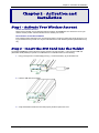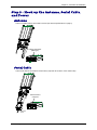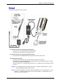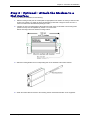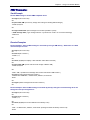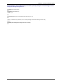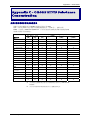
1
®
MultiModem GPRS
Wireless Modem
MTCBA-G-F4
User Guide
Copyright and Technical Support
MultiModem® GPRS User Guide
Wireless Modem
MTCBA-G-F4
S000443A, Revision A
Copyright
This publication may not be reproduced, in whole or in part, without prior expressed written permission from MultiTech Systems, Inc. All rights reserved.
Copyright © 2007 by Multi-Tech Systems, Inc.
Multi-Tech Systems, Inc. makes no representation or warranties with respect to the contents hereof and specifically
disclaims any implied warranties of merchantability or fitness for any particular purpose.
Furthermore, Multi-Tech Systems, Inc. reserves the right to revise this publication and to make changes from time to
time in the content hereof without obligation of Multi-Tech Systems, Inc., to notify any person or organization of such
revisions or changes. Check Multi-Tech’s Web site for current versions of our product documentation.
Revision History
Revision Date
A
10/03/07
Description
Initial Release
Trademarks and Logos
The Multi-Tech logo and MultiModem are registered trademarks of Multi-Tech Systems, Inc. Windows is a registered
trademark of Microsoft in the U.S. and other countries. Other trademarks and trade names mentioned in this
publication belong to their respective owners.
Technical Support
Country
Europe, Middle East, Africa:
U.S., Canada, all others:
By Email
[email protected]
[email protected]
By Phone
+(44) 118 959 7774
800-972-2439 or 763-717-5863
World Headquarters
Multi-Tech Systems, Inc.
2205 Woodale Drive
Mounds View, Minnesota 55112
Phone: 763-785-3500 or 800-328-9717
Fax: 763-785-9874
Internet Address: http://www.multitech.com
Multi-Tech Systems, Inc. MultiModem GPRS Wireless Modem User Guide
2
Table of Contents
Contents
Chapter 1 – Product Description and Specifications................................................................................................4
Product Description..............................................................................................................................................4
Features .................................................................................................................................................................4
Safety .....................................................................................................................................................................5
General Safety .................................................................................................................................................5
RF Interference Issues.....................................................................................................................................5
Installation Instructions and Hazardous Locations Warnings ...........................................................................5
Vehicle Safety ..................................................................................................................................................5
Maintenance of Your Modem ...........................................................................................................................6
Your Responsibility ..........................................................................................................................................6
Package Contents.................................................................................................................................................6
General Specifications .........................................................................................................................................7
Functions – GSM/GPRS Modes ...........................................................................................................................7
Electrical Specifications.......................................................................................................................................7
RF Specifications..................................................................................................................................................8
Antenna Specifications ........................................................................................................................................8
GSM/EGSM Antenna Requirements/Specifications.........................................................................................8
Antennas Available from Multi-Tech Systems, Inc. ..........................................................................................8
PTCRB Requirements Note.............................................................................................................................8
FCC Requirements Note..................................................................................................................................8
Interfaces ...............................................................................................................................................................8
LEDs ................................................................................................................................................................8
RS232 15-Pin Connector Pinout ..........................................................................................................................9
AT Command Information ....................................................................................................................................9
Chapter 2 – Activation and Installation ....................................................................................................................10
Step 1 – Activate Your Wireless Account .........................................................................................................10
Step 2 – Insert the SIM Card into the Holder ....................................................................................................10
Step 3 – Hook up the Antenna, Serial Cable, and Power.................................................................................11
Step 4 – Optional – Attach the Modem to a Flat Surface .................................................................................13
Step 5 – Install the Modem Driver......................................................................................................................14
Chapter 3 – Using Your Wireless Modem ................................................................................................................15
Phone Numbers for the Wireless Modem .........................................................................................................15
Examples of Useful AT Commands...................................................................................................................15
Verifying Signal Strength ...............................................................................................................................15
Checking Network Registration and Roaming Status.....................................................................................15
Checking the Modem’s Identity ......................................................................................................................15
Establishing a Voice Call ...............................................................................................................................16
Establishing a Circuit-Switched Data (CSD) Connection ...............................................................................16
Answering a Circuit-Switched Data (CSD) Connection ..................................................................................16
Using Short Message Services (SMS)...............................................................................................................17
SMS Examples ..............................................................................................................................................18
Internet Access ...................................................................................................................................................20
Connecting to the GPRS Network for Internet Access...................................................................................20
Chapter 4 – Troubleshooting and Frequently Asked Questions............................................................................22
Troubleshooting Examples ................................................................................................................................22
Frequently Asked Questions .............................................................................................................................23
Chapter 5 – Reference Information...........................................................................................................................25
Wireless Modem Reference Information...........................................................................................................25
Data Cable Diagram – No Voice ....................................................................................................................25
Data Cable Diagram – with Voice ..................................................................................................................26
Fused DC Power Cable Dimensions..............................................................................................................26
How to Change the Fuse ...............................................................................................................................26
Appendix A – Warranty and Repairs ........................................................................................................................27
Appendix B - Waste Electrical and Electronic Equipment (WEEE) Statement .....................................................29
Appendix C – C-ROHS HT/TS Substance Concentration........................................................................................30
Multi-Tech Systems, Inc. MultiModem GPRS Wireless Modem User Guide
3
Chapter 1 – Product Description and Specifications
Chapter 1 – Product Description
and Specifications
Product Description
The Multi-Tech MultiModem® GPRS is an external data/fax/voice wireless modem. It also supports mobile originated
short message service (SMS) and mobile-terminated SMS. It offers standards-based multi-band GPRS Class 10
performance. This ready-to-deploy, standalone modem allows developers to add wireless communication to products
with a minimum of development time and expense. The MultiModem GRPS Wireless Modem is based on industrystandard open interfaces, is fully type approved, and can be desktop or panel mounted.
Other Product Codes:
NAM is the model for US and Canada
GB/IE is the model for Great Britain and Ireland
Euro/ROW is the model for Europe and the rest of the world
A Note About Documentation:
Multi-Tech Systems, Inc. reserves the right to revise this publication and to make changes from time to time in the
content hereof without obligation of Multi-Tech Systems, Inc., to notify any person or organization of such revisions or
changes. Check Multi-Tech’s Web site for current versions of our product documentation.
Features
•
•
•
•
•
•
•
•
•
•
•
•
•
•
•
•
•
•
•
•
GPRS Class 10 operation
Quad-band 850/900/1800/1900
GSM Class 1 and Class 2 Group 3 FAX
Desktop or panel mounting
Short Message Services including text and PDU, point-to-point, cell broadcast
14.4K GSM circuit switched data
SMA antenna connector and SIM socket
Serial interface supports DTE speeds to 115.2K
AT command compatible
MNP2 V.42bis data compression
Numerous LEDs provide operational status
ME + SIM phone book management
Fixed dialing number
SIM Toolkit Class 2
SIM, network and service provider locks
Real time clock
Alarm management
UCS2 character set management
Packet data up to 85K bps
Embedded TCP/IP stack
Multi-Tech Systems, Inc. MultiModem GPRS Wireless Modem User Guide
4
Chapter 1 – Product Description and Specifications
Safety
General Safety
The modem is designed for and intended to be used in fixed and mobile applications. “Fixed” means that the device is
physically secured at one location and is not able to be easily moved to another location. “Mobile” means that the
device is designed to be used in other than fixed locations.
Caution: Maintain a separation distance of at least 20 cm (8 inches) is normally maintained
between the transmitter’s antenna and the body of the user or nearby persons. The Modem
is not designed for or intended to be used in portable applications within 20 cm. (8 inches) of
the body of the user.
RF Interference Issues
It is important to follow any special regulations regarding the use of radio equipment due in particular to the possibility
of radio frequency, RF, interference. Please follow the safety advice given below carefully.
• Switch OFF your Wireless MultiModem when in an aircraft. The use of cellular telephones in an aircraft may
endanger the operation of the aircraft, disrupt the cellular network and is illegal. Failure to observe this
instruction may lead to suspension or denial of cellular telephone services to the offender, or legal action or
both.
• Switch OFF your Wireless MultiModem when around gasoline or diesel-fuel pumps and before filling your
vehicle with fuel.
• Switch OFF your Wireless MultiModem in hospitals and any other place where medical equipment may be in
use.
• Respect restrictions on the use of radio equipment in fuel depots, chemical plants or where blasting operations
are in progress.
• There may be a hazard associated with the operation of your Wireless MultiModem close to inadequately
protected personal medical devices such as hearing aids and pacemakers. Consult the manufacturers of the
medical device to determine if it is adequately protected.
• Operation of your Wireless MultiModem close to other electronic equipment may also cause interference if the
equipment is inadequately protected. Observe any warning signs and manufacturers’ recommendations.
Installation Instructions and Hazardous Locations
Warnings
1.
2.
3.
4.
5.
6.
The modems are open devices intended for installation in an ultimate enclosure suitable for the intended
application.
THIS EQUIPMENT IS SUITABLE FOR USE IN CLASS I, DIVISION 2, GROUPS A, B, C, AND D OR NONHAZARDOUS LOCATIONS ONLY.
“WARNING – Explosion Hazard – Substitution of Components may Impair Suitability for Class I Division 2”.
“WARNING – Explosion Hazard – Do not Disconnect Equipment Unless Power has been switched off or the
area is known to be Non-Hazardous”.
“WARNING – Explosion Hazard - Do not replace the Fuse Unless Power has been switched off or the area
is known to be Non-Hazardous”.
“WARNING – Do not install or remove SIM card unless power has been switched off or the area is known to
be Non-Hazardous”.
Vehicle Safety
• Do not use your MultiModem while driving.
• Respect national regulations on the use of cellular telephones in vehicles. Road safety always comes first.
• If incorrectly installed in a vehicle, the operation of Wireless MultiModem telephone could interfere with the
correct functioning of vehicle electronics. To avoid such problems, be sure that qualified personnel have
performed the installation. Verification of the protection of vehicle electronics should be part of the installation.
• The use of an alert device to operate a vehicle’s lights or horn on public roads is not permitted.
Multi-Tech Systems, Inc. MultiModem GPRS Wireless Modem User Guide
5
Chapter 1 – Product Description and Specifications
Maintenance of Your Modem
Your Wireless MultiModem is the product of advanced engineering, design, and craftsmanship and should be treated
with care. The suggestions below will help you to enjoy this product for many years.
• Do not expose the Wireless MultiModem to any extreme environment where the temperature is above 50ºC or
humidity is above 90% noncondensing.
• Do not attempt to disassemble the Wireless MultiModem. There are no user serviceable parts inside.
• Do not expose the Wireless MultiModem to water, rain, or spilled beverages. It is not waterproof.
• Do not place the Wireless MultiModem alongside computer discs, credit or travel cards, or other magnetic
media. The phone may affect the information contained on discs or cards.
• The use of accessories not authorized by Multi-Tech or not compliant with Multi-Tech's accessory
specifications may invalidate the warranty of the Wireless MultiModem.
• In the unlikely event of a fault in the Wireless MultiModem, contact Multi-Tech Tech Support.
Your Responsibility
This Wireless MultiModem is your responsibility. Please treat it with care respecting all local regulations. It is not a toy.
Therefore, keep it in a safe place at all times and out of the reach of children.
Try to remember your Unlock and PIN codes. Become familiar with and use the security features to block
unauthorized use and theft.
Package Contents
Unbundled Package
Modem with No Accessories
1 modem
1 mounting bracket
1 fused DC power cable
1 Quick Start Guide
1 MultiModem CD
Note: You must supply bracket
screws and an antenna.
Bundled Package
Modem with Accessories
1 modem
1 mounting bracket
1 antenna
1 serial cable
1 DC power supply/cable (varies)
4 rubber feet
1 Quick Start Guide
1 MultiModem CD
Note: You must supply bracket
screws.
Note:
Your wireless provider will supply the SIM card.
Multi-Tech Systems, Inc. MultiModem GPRS Wireless Modem User Guide
6
Chapter 1 – Product Description and Specifications
General Specifications
General Specifications
Power Requirements
5 V to 32VDC; 400mA Average @5V, 1A Peak @ 5V
Mechanical Dimensions & Weight
4.3" L x 2.4" W x 0.94" H; 4.2 oz.
(11 cm x 6.1 cm x 2.4 cm; 119 g)
Connectors & Fasteners
Antenna Connection type: SMA jack
Serial Connector: DE15
Pins: RS232 link, audio link, BOOT, RESET
Power Connector: 2.5mm miniature power jack
SIM receptacle: standard 3V
Operating Temperatures
-30° to +70°C
Storage Temperatures
-40° to +85°C
Humidity
Relative humidity 20% to 90% noncondensing
Certifications
CE Mark, R&TTE
EMC: FCC Part 2, 15, 22, 24, EN 55022 & EN 55024
Safety: cUL, UL 60950, EN 60950
Network: PTCRB
Functions – GSM/GPRS Modes
Mode
Standard
Interface
SMS
Data
Fax
GPRS
Description
Quad Band 850/900/1800/1900 MHz
Serial interface RS-232. V.24/V.28 Autobauding function.
Mobile Originated (MO) and Mobile Terminated (MT) SMS Mode Text & PDU point to point. Cell
broadcast in accordance with GSM 07.05.
Data circuit asynchronous, transparent, non-transparent up to 14,400 bits
Class 1 and Class 2 Group 3 compatible.
Class 10. Coding schemes: CS1 to CS4.
Electrical Specifications
Electrical Characteristics
Switching on/off
The device is permanently powered (when connected to the power supply).
Voltage Range
Voltage range : 5 to 32V DC
GND : 0V
Over voltage and under voltage
Correct operation of the Wireless MultiModem in communication mode is
not guaranteed if input voltage falls below 5V.
Input/output electrical characteristics for external connections
Parameters
GSM/GPRS 850/900 GSM/GPRS 1800/1900 Unit
Typ.
Typ.
Input Supply Voltage
5
13.2
32
5
13.2
32
V
Input peak supply current in comm. mode at Pmax
1
.4
.2
1
.4
.2
A
Input average supply current in comm. mode at Pmax
360
150
75
300
125
70
mA
Input average supply current in idle mode
30
10
10
30
10
10
mA
Multi-Tech Systems, Inc. MultiModem GPRS Wireless Modem User Guide
7
Chapter 1 – Product Description and Specifications
RF Specifications
Frequency RX
Frequency TX
RF Power Stand
GSM 850
869 to 894 MHz
824 to 849 MHz
2W at 12.5% duty
cycle
EGSM 900
925 to 960 MHz
880 to 915 MHz
2W at 12.5% duty
cycle
GSM 1800
1805 to 1800 MHz
1710 to 1785 MHz
1W at 12.5% duty
cycle
GSM 1900
1930 to 1990 MHz
1850 to 1910 MHz
1W at 12.5% duty
cycle
Antenna Specifications
GSM/EGSM Antenna Requirements/Specifications
Frequency Range:
Impedance:
VSWR:
Typical Radiated Gain:
Radiation:
Polarization:
Wave:
824 – 960 MHz / 1710 – 1990 MHz
50 Ohms
<2.0:1
3 dBi on azimuth plane
Omni
Vertical
Half Wave Dipole
Antennas Available from Multi-Tech Systems, Inc.
Description
Part Number
Hinged Right Angle 900/1800 MHz Cellular Modem Antenna
ANF1-1HRA
Hinged Right Angle 800/1900 MHz Cellular Modem Antenna
ANF21HRA
Hinged Right Angle 850/900/1800/1900 MHz Cellular Modem Antenna ANQB-1HRA
PTCRB Requirements Note
There cannot be any alteration to the authorized antenna system. The antenna system must be the same type
with similar in-band and out-of-ban radiation patterns and maintain the same specifications.
FCC Requirements Note
The antenna gain, including cable loss, must not exceed 3.0 dBi at 1900 MHz / 1.6 dBi at 850 MHz for mobile
operating configurations and 7.0 dBi at 1900 MHz / 2.3 dBi at 850 MHz for fixed mounted operations, as defined
in 2.1091 and 1.1307 of the rules for satisfying RF exposure compliance.
Interfaces
The Wireless MultiModem has several interfaces:
•
LED function indicating operating status
•
External antenna (via SMA connector)
•
Serial and control link (via 15 pins SUB D)
•
Power supply (via 2.5mm miniature power jack)
•
SIM card holder
LEDs
LED Indicators
TD
RD
CD
LS
TR
PWR
Transmit Data. Lit when modem is transmitting data.
Receive Data. Lit when modem is receiving data.
Carrier Detect. Lit when data connection has been established.
Line Status.
Continuous “on” state indicates that the wireless modem is not registered on the network.
Flashing state indicates registration on network.
Off state. Modem is off (not ready) or in download mode.
Terminal Ready. Commonly called “Data Terminal Ready.” This is a readiness signal from the PC.
Power. Indicates presence of DC power when lit.
Multi-Tech Systems, Inc. MultiModem GPRS Wireless Modem User Guide
8
Chapter 1 – Product Description and Specifications
RS232 15-Pin Connector Pinout
5
10
15
RS-232
Audio
Boot
Reset
PIN
1
6
2
8
9
7
12
11
13
4
5
10
15
3
14
EIA
DCD
RX
TX
DTR
GND
DSR
RTS
CTS
RI
MICROPHONE (+)
MICROPHONE (-)
SPEAKER (+)
SPEAKER (-)
BOOT
RESET
1
6
11
CCIT
109
104
103
108.2
107
105
106
125
Designation
Data Carrier Direct
Receive Data (out)
Transmit Data
Data Terminal Ready
Signal Ground
Data Set Ready
Request to Send
Clear to Send
Ring Indicator
For factory use only.
To reset, connect to GND momentarily (typical:
2mSec). Open for normal operation.
AT Command Information
AT commands for the GPRS wireless modem are published in a separate Reference Guide included on the
MultiModem CD and posted on the Multi-Tech web site.
IP commands for GPRS modems are also published in a separate Reference Guide included on the MultiModem
CD and posted on the Multi-Tech web site.
Multi-Tech Systems, Inc. MultiModem GPRS Wireless Modem User Guide
9
Chapter 2 – Activation and Installation
Chapter 2 – Activation and
Installation
Step 1 – Activate Your Wireless Account
Activate Your Wireless Account
Please see the wireless account Activation Notices located on the MultiModem CD. Choose the one for your
wireless network provider and follow the directions to activate your account.
Phone Numbers for the Wireless Modem
Every wireless modem will have its own unique phone number. The phone number may simply be given to you
by your wireless service provider or it may be on the SIM card or both. Wireless provider implementations may
vary.
Step 2 – Insert the SIM Card into the Holder
The wireless MultiModem requires the power supply connection to begin operation. It also requires a SIM card
(Subscriber Identity Module) to operate on a GSM network. To install the modem, do the following:
1. Using your fingernail or a small wedging tool (e.g., a small screwdriver), pry off the SIM cover.
2. Insert the SIM card into the holder.
3. Verify that the SIM card fits into the holder properly and then replace the cover.
Multi-Tech Systems, Inc. MultiModem GPRS Wireless Modem User Guide
10
Chapter 2 – Activation and Installation
Step 3 – Hook up the Antenna, Serial Cable,
and Power
Antenna
Connect a suitable antenna to the SMA connector (see antenna specifications on page 9).
Antenna Connector
(SMA type)
Serial Cable
Connect both sides of the serial and control cable (15-pin Sub D connector on the modem side).
Serial & Control
Connector
To Serial Port
of PC
Multi-Tech Systems, Inc. MultiModem GPRS Wireless Modem User Guide
11
Chapter 2 – Activation and Installation
Power
Plug the power supply cable into the modem.
For Two-Piece Transformer Power Supply (International).
• Connect the AC cord receptacle into the transformer block.
• Connect the AC cord plug into the mains power outlet.
For One-Piece Transformer Power Supply (North America).
• Connect between the MultiModem power receptacle and the mains power outlet.
For Optional Direct DC Power
• Connect the fused DC power cable into the DC power connector on the modem.
• Then attach the two wires at the other end of the fused cable to a DC fuse/terminal block on a vehicle
in which you are mounting the MultiModem.
• Connect red wire to the "+" (positive) and black wire to the "–" (negative). Be sure the GND connection
is correct.
Warning: Over-voltage protection is provided on the device. To ensure complete protection, you may
want to add additional filtering to the DC input.
Note: For automotive application: according to the type of application, you can use permanent “+” or keyswitched “+”. Connect the power supply to its source (for example, in a mobile situation, to the
vehicle’s DC fuse/terminal block).
Multi-Tech Systems, Inc. MultiModem GPRS Wireless Modem User Guide
12
Chapter 2 – Activation and Installation
Step 4 – Optional – Attach the Modem to a
Flat Surface
To mount the Wireless MultiModem, do the following:
1.
Obtain mounting screws (two are needed) that are appropriate for the surface on which you will mount the
modem. For example, one might use two 6-32 self-tapping screws 5/8” in length to mount the unit in a
truck to the wall of the cab behind the passenger’s seat.
2. Typically, the unit is mounted against a flat surface into which holes can be drilled. The mounting holes
(center-to-center) must be separated by 125mm or 4 -15/16 inches.
Drill the mounting holes at the desired mounting location.
3. Slide the mounting bridles into the corresponding slots on the backside of the modem chassis.
4. Attach the modem with two screws to the mounting surface at the desired location on the equipment.
Multi-Tech Systems, Inc. MultiModem GPRS Wireless Modem User Guide
13
Chapter 2 – Activation and Installation
Step 5 – Install the Modem Driver
Introduction
Compatibility: The wireless modem is compatible with Windows 2000/2003+, Windows XP, and Linux.
Windows: Windows operating systems require a modem driver to be installed. See the example below for
installing a GPRS modem driver onto a PC with Windows XP/2003.
Linux: Linux does not require a driver for serial modems.
Requirements
• One MTCBA-G modem
• A RS232 cable to connect the modem to the PC
• The MultiModem CD that was shipped with the Multi-Tech modem
• A PC running Windows
Note: This installation procedure is only used as a basic guide to help you install the Multi-Tech Wireless modem
driver. You may see differences based upon your version of Windows and your Windows settings.
Installing the Multi-Tech MTCBA-G Modem Driver onto a PC Running Windows XP/2003
This installation assumes a Windows XP or 2003 operating system. XP and 2003 are identical in the methods they
use for installing modem drivers.
To load the MultiModem wireless modem’s driver on your PC, select the Control Panel’s Phone and Modem Options
option. During this installation, you will be required to browse the MultiModem CD to load the modem’s INF file. This
file is located at the root directory on the MultiModem CD.
1. Go to Start, and then click on Control Panel.
2.
In the Control Panel, double-click on Phone and Modem Options. When the Phone and Modem Options
screen appears, click on the tab labeled Modems.
3.
Click on Add to add a new modem.
4.
On the Install Modem screen, click Don’t detect my modem, I will select it from a list. Then click Next >.
5.
On the next screen, click the Have Disk button to browse for the driver file on the MultiModem CD.
6.
Make sure that the Multi-Tech system CD is inserted into your CD-ROM then click on Browse.
7.
Browse to the root directory of your CD-ROM drive and then click on Open.
8.
The Install From Disk screen should now show the directory of your CD-ROM. Click on OK.
9.
On this next screen, scroll down the list of modems and select the model that is applicable to your modem.
Once you have selected your model, click on Next>.
10.
You will now have to choose which com port the Multi-Tech modem is connected to. If you know exactly
which port your modem is on, click on that port; other wise, choose COM1 (most common). Click Next >.
11.
You will now be prompted with a screen that states that the Multi-Tech driver has not passed Windows logo
testing. You can ignore this message and click Continue Anyway.
12.
To finish the install, click on Finish.
You have now successfully installed the Multi-Tech wireless modem driver to your PC.
Verifying That Your Modem Has Been Installed Successfully
1.
After you have successfully installed the Multi-Tech modem driver as stated above, you should be brought
back to the Phone and Modems Options screen. Make sure that the modem is now listed under the columns
Modem and Attached To (the correct com port).
2.
Highlight the modem and then click on Properties.
3.
A Properties screen will open for the Multi-Tech modem. Click on the tab labeled Diagnostics.
4.
In the middle of the screen, click on the Query Modem button. Windows will now try to query the Multi-Tech
modem. If this process passes, the second box on this screen will show the columns Command and
Response.
Note: To make sure that the modem is correctly being queried, look at the LED lights of the modem after
you click on Query Modem. The TR light should come on and the TD and RD lights should flicker.
5.
If this process passes, then the modem should be properly installed and ready for use. Click OK to close the
modem Properties window. Then click on OK to close the Phone and Modem Options window.
Multi-Tech Systems, Inc. MultiModem GPRS Wireless Modem User Guide
14
Chapter 3 – Using Your Wireless Modem
Chapter 3 – Using Your Wireless
Modem
Phone Numbers for the Wireless Modem
• Every wireless modem will have its own unique phone number.
• The phone number may simply be given to you by your wireless service provider or it may be on the SIM card
or both. Wireless provider implementations may vary.
Examples of Useful AT Commands
A Note About HyperTerminal
In order to verify signal strength and roaming status, you must use a terminal application such as HyperTerminal. To
open this program in Windows XP or Windows 2003, go to Start > All Programs > Accessories > Communications
> HyperTerminal. Other Windows operating systems have similar paths to HyperTerminal. See your system’s online
Help if you cannot find it.
A Note About AT Commands
AT commands can be used to operate, configure, and query your modem. A reference guide to the GPRS commands
is included on the MultiModem CD and on the Multi-Tech Web site.
The following two commands let you query signal strength and roaming status.
Verifying Signal Strength
Using HyperTerminal, type AT+CSQ
The modem responds with the received signal strength (rssi).
The modem responds with the received signal strength (rssi) and the channel bit error rate (ber).
RSSI ranges from 0 to 31.
Signal Strength Verification – RSSI
21 – 31
Exceptional
11 - 20
Average
0 - 10
Weak or Insufficient
99
No signal
BER ranges from 0 to 7 (Seven is the highest error rate).
Checking Network Registration and Roaming Status
In this procedure, you will verify that the Wireless MultiModem has been registered on the wireless network.
Using HyperTerminal, type AT+CREG?
The modem will respond in one of the following ways:
Value
0,0
0,1
0,5
Network Registration Verification
Network Registration Status
The modem is not registered on any network
The modem is registered on the home network
The modem is registered on a network and it is roaming
Note: If the modem indicates that it is not registered, verify the signal strength to determine if the problem
is the strength of the received signal.
Checking the Modem’s Identity
Use the ATI command (Note: This command is illustrated using the capital letter i after AT)
• Type ATI0 (Note: The command ends in a zero)
The manufacturing data displays. For example: Wavecom Modem Multiband G850 1900
• Type ATI3
The software version displays. For example: 651_09gg...
• Type ATI6
Displays modem data features. For example: data rates, data modes, fax classes.
Multi-Tech Systems, Inc. MultiModem GPRS Wireless Modem User Guide
15
Chapter 3 – Using Your Wireless Modem
Establishing a Voice Call
• Enter PIN Code (if required by your wireless provider)
Type AT+CPIN=1234
Responses:
OK (PIN Code accepted)
+CME ERROR : 16 (Incorrect PIN Code)
+CME ERROR : 3 (PIN already entered [with +CMEE : 1 mode])
• Initiate a voice call
Type ATD1234; (Note: Don’t forget the semicolon “;” at the end. This stands for voice calls)
Responses:
OK (Communication established)
CME ERROR : 11 (PIN Code not entered [with +CMEE : 1 mode])
CME ERROR : 3 (Operation not allowed)
• Initiate an emergency call
Type ATD112; (Note: Don’t forget the semicolon “;” at the end. This stands for voice calls)
Responses:
OK
• Hang up
Type ATH
Responses:
OK
Establishing a Circuit-Switched Data (CSD) Connection
A Circuit-Switched Data Connection makes the wireless modem work similar to a regular analog modem. You
must have CSD service in order to make a CSD call.
Note: Your wireless service provider charges airtime usage for these connections.
Establish a Connection: Using HyperTerminal or a terminal application, you can establish a CSD
connection by entering the following command: ATD<phone number>
Notes:
• The phone number you are calling is entered between the displayed
brackets. Do not type additional brackets. For example, type only ATD
8585551212. 8285551212 is typed between the brackets.
• This command tells the modem to inform the wireless network that you are
initiating a CSD modem call. If you are dialing to another modem, the
remote modem should answer and a connection between the two modems
will be established. If you include a semi-colon (;) at the end of the dialing
string, the modem will instead initiate a Voice call to the phone number
dialed.
Disconnect:
Type: +++
Wait about two seconds to see an OK response.
Then type: ATH
Note: +++ is the escape sequence and ATH is the Hang-up command.
Answering a Circuit-Switched Data (CSD) Connection
A Circuit-Switched Data Connection makes the wireless modem work similar to a regular analog modem. You
must have CSD service in order to answer a CSD call.
There are three phone numbers for GSM: the voice number, the data number, and the fax number. All are
provided by the carrier. To answer a call:
Establish A Connection: Call into the modem by dialing the data number provided by your carrier.
Answer a Call:
When you see the RING responses on the terminal screen, enter ATA <cr> to
answer the call.
Set Auto-Answer:
Enter ATS0=x
This sets the modem to auto-answer. The call will be answered after the number
of rings entered. x stand for the number rings.
Then call into the number provided to you by the carrier.
Disconnect:
Type: +++
Wait about one second to see an OK response.
Then type: ATH
Multi-Tech Systems, Inc. MultiModem GPRS Wireless Modem User Guide
16
Chapter 3 – Using Your Wireless Modem
Using Short Message Services (SMS)
Send a Short Message to a Specified Number.
Type AT+CMGS="8585551212" <press Enter>
Then type your message: Please call me soon. <press ctrl Z>
The modem may respond with +CMGS:<mr> OK
Write a Message to Memory.
You can store a message to send it at a later date.
Type AT+CMGW="8585551212" <press Enter>
Type the message. <press ctrl Z>
The modem may respond with +CMGW: 4 OK (The message is stored in the index as message 4.)
Send a Message from Storage.
Type AT+CMSS=x,"8585551212" <press Enter>
The modem may respond with +CMSS: 1 OK (The transmission is successful. One SMS message is
sent.)
Note: The x represents an index location.
View a List of Stored Messages.
Type AT+CMGL=x <press Enter>
For x, substitute one of the following:
"REC UNREAD" Shows received unread messages.
"REC READ" Shows received read messages.
"STO UNSENT" Shows stored unsent messages.
"STO SENT" Shows stored sent messages.
"ALL" Shows messages.
The modem will respond AT+CMGL: 1,"REC UNREAD","8585551212",1...
The modem will continue until all UNREAD messages, numbers, and index number are listed.
Read a Stored Message.
Type AT+CMGR=x <press Enter>
The modem may respond with +CMGR: "REC READ", "8585551212", ......
Note: The x represents an index location.
Delete a Stored Message.
Type AT+CMGD=x,n <press Enter>
If you want to delete one message at a time, do not enter a value for n.
For n, substitute one of the following:
0 Delete message at location <include the index number>
1 Delete all READ messages.
2 Delete all READ and SENT messages.
3 Delete all READ, SENT, and UNSENT messages.
4 Delete ALL messages.
The modem will respond OK.
Note: The x represents an index location. The n stands for the type of messages to delete.
Multi-Tech Systems, Inc. MultiModem GPRS Wireless Modem User Guide
17
Chapter 3 – Using Your Wireless Modem
SMS Examples
Send Example
Send an SMS message to another SMS compatible device
at+cmgf=1 (set to text mode)
OK
at+cpms="SM","SM" (set memory storage when writing and sending SMS messages)
+CPMS: 0,50,0,50
OK
at+cmgs="7632273726" (send message to the number specified in quotes)
> TEST message ONE. ( Type message after the > symbol and hit <CTRL + Z> to send the message)
+CMGS: 52
OK
Receive Examples
Receive Example 1: Receive SMS messages in text mode by saving to SIM memory – Notification via +CMTI
unsolicited response code:
at+cmgf=1 (set to text mode)
OK
at+csms=0 (set to Phase 1)
+CSMS: 1,1,1
OK
at+cnmi=2,1,0,0,0 (set to display +CMTI indication when SMS is received)
OK
at+cpms="SM","SM" (set the read and write storage of SMS to SIM)
+CPMS: 0,50,0,50
OK
+CMTI: "SM",1 (indication that message was received and stored to SIM location 1)
at+cmgr=1 (read message stored in location 1)
+CMGR: "REC UNREAD","+17632273726",,"06/03/17,13:55:22+00"
TEST1
OK
at+cmgd=1 (delete message that is stored in location 1)
OK
Receive Example 2: Receive SMS message in text mode by directly routing the received message to the TE
through the serial port using Phase 2:
at+cmgf=1 (set to text mode)
OK
at+csms=0 (set to Phase 2)
+CSMS: 1,1,1
OK
at+cnmi=2,2,0,0,0 (set to receive SMS and route directly to TE)
OK
+CMT: "+17632273726",,"06/03/17,13:59:18+00" (message received and directly routed to TE)
TEST2
Multi-Tech Systems, Inc. MultiModem GPRS Wireless Modem User Guide
18
Chapter 3 – Using Your Wireless Modem
Receive Example 3: Receive SMS message in text mode by directly routing the received message to the TE
through the serial port using Phase 2+:
at+cmgf=1 (set to text mode)
OK
at+csms=1 (set to Phase 2+)
+CSMS: 1,1,1
OK
at+cnmi=2,2,0,0,0 (set to receive SMS and route directly to TE)
OK
+CMT: "+17632273726",,"06/03/17,14:01:17+00" (message received and directly routed to TE)
TEST3
at+cnma (acknowledge that message has been received)
OK
Multi-Tech Systems, Inc. MultiModem GPRS Wireless Modem User Guide
19
Chapter 3 – Using Your Wireless Modem
Internet Access
Internet access can be setup in Windows Dial-Up Networking (DUN) of the computer that the wireless modem is
serving. Setup procedures will vary according to the type of wireless service provider used. To access Dial-Up
Networking on your PC, go to Start > Settings > Network Connections.
•
For GSM-without-GPRS, a circuit-switched data connection is used. The user can set up DUN to
make a conventional V.32 modem connection to any terminating modem at the other end. The phone
number specified in DUN can be one supplied by the wireless service provider or another phone
number related to a different dialup modem service (e.g., a dialup modem service phone number from
any commercial or private dialup network).
•
For GSM-with-GPRS, a single DUN number is generally used by all of a wireless provider’s
subscribers throughout its area of coverage; regional, nationwide, continental, etc. Rather than being
a literal phone directory number, as in conventional DUN, this is a code that gives the modem Internet
access.
Connecting to the GPRS Network for Internet Access
After you have inserted the SIM card and the modem is ready for use, you can establish an Internet connection
through a Windows dial-up session.
Note that your wireless provider will charge you for data usage.
Requirements
• One Multi-Tech wireless GPRS modem
• The GPRS modem should have an active SIM card and must have GPRS services
• The modem must be getting a proper signal and be showing a network registration through the wireless
provider’s network
• A PC running Windows XP or 2003 with the Multi-Tech drivers installed for your particular model
The following instructions are for Windows XP SP2 and Windows 2003. Every PC may have slight
differences which may cause the instructions to be different. Use these instructions as a guide to help you
understand what is required to set up an Internet connection through your wireless service provider for all
operating systems.
Note: Cellular providers provide Internet services as part of your service plan. Multi-Tech recommends that if
you plan on using large amounts of data, to sign up for an unlimited data service plan with your provider.
Multi-Tech Systems, Inc. will not be responsible for any charges on your cellular bill. If you have any
questions about billing, service plans, service charges, etc., please contact your provider for more
information.
Set the Access Point Name (APN) into the Modem’s Properties on Your PC
In order for your GPRS wireless modem to connect to your provider’s network, you must tell the modem the
Access Point Name (APN) to which it will connect. The APN is a server name that your account is setup on
with your provider. Your APN will be given to you by your provider. Here are some well-known APNs:
• AT&T: PROXY, or INTERNET, or PUBLIC
• T-Mobile: INTERNET2.VOICESTREAM.COM, or INTERNET3.VOICESTREAM.COM, or
WAP.VOICESTREAM.COM
• Rogers AT&T of Canada: INTERNET.COM
Steps for Setting the APN
1.
2.
3.
4.
Start by clicking on Start and then clicking on Control Panel.
In the Control Panel, double-click on Phone and Modem Options.
The Phone and Modem Options window appears. Click on the tab labeled Modems. Highlight the
Multi-Tech wireless modem listed in the table and then click on Properties.
A Properties window for your modem will display. Click on the Advanced tab and you should see
an Extra Settings box. In the Extra initialization commands text box, type:
AT+CGDCONT=1,”IP”,”<APN>”
For <APN>, type in the correct APN for your account. For example:
AT+CGDCONT=1,”IP”,”ISP.AT&T”
Click OK to close the modem Properties window. Then click OK to close the Phone and
Modem Options window.
Multi-Tech Systems, Inc. MultiModem GPRS Wireless Modem User Guide
20
Chapter 3 – Using Your Wireless Modem
Create Your Dial-Up Connection in Windows XP/2003
1.
Click on Start and then click on Control Panel.
2.
In the Control Panel, double-click on Network Connections.
3.
On the Network Connections screen on the left-hand side under Network Tasks, click on Create a new
connection.
4.
The New Connection Wizard should appear. It will walk you through setting up your Internet connection.
Click on Next > to begin.
5.
On the Network Connection Type screen, select Connect to the Internet, and then click Next >.
6.
On the Getting Ready screen, select Set up my connection manually, and then click Next >.
7.
On the Internet Connection screen, select Connect using a dial-up modem, and then click Next >.
Note: After clicking on Next, you may or may not be asked to select which modem to use. If you have
more than one modem installed in your PC, you will be required to select the proper modem to use. If
asked, please select the Multi-Tech wireless modem that has been installed.
8.
On the Connection Name screen in the ISP Name box, type in a name for your new connection. You
can give it any name that you would like. After you have typed in a name, click Next >.
On the Phone Number to Dial screen, type in the number that specifies to the modem to connect to your
provider’s Internet service.
9.
For GPRS modems, type in the number *99***1#.
Then click Next >.
10.
On the Connection Availability screen, specify if this connection is for anyone’s use or for your use only
by checking the appropriate button. Choose your preference, and then click Next>.
11.
On the Internet Account Information screen, type the user name and the password for your account. In
many cases, a user name and a password are not required, but some wireless providers require it.
Check with your provider to see if they are needed.
Check the following two options if you would like them activated:
Check the box if you want this account name and password to be used by everyone.
Check the box if you want this as your default Internet connection. Then click Next >.
12.
On the Completing the New Connection Wizard screen, you last task is to place a check in the box if
you would like to add a shortcut to your desktop. Then click Finish.
13.
A Connection screen displays on your desktop. Click the Properties button on the bottom of this
screen.
14.
The Properties window will open for you to make your connection. Important: Make sure that Use
dialing rules is not selected, and then click OK.
15.
Once back at your Connection screen, click the Dial button at the bottom of the screen to start the
connection.
16.
The connection will now tell the modem to connect to your provider’s Internet service. Once connected,
you should see the connection status icon in your system tray at the bottom right-hand corner of your
screen.
You should now be able to open Internet Explorer or any other browser of your preference to surf the
Internet.
Disconnecting the Connection:
1.
To disconnect the connection, right click on the connection icon in your system tray at the bottom righthand corner of your screen.
2.
Scroll up and click on Disconnect.
Your should now be disconnect from the Internet.
Multi-Tech Systems, Inc. MultiModem GPRS Wireless Modem User Guide
21
Chapter 4 – Troubleshooting and Frequently Asked Questions
Chapter 4 – Troubleshooting and
Frequently Asked Questions
Troubleshooting Examples
Before calling the Multi-Tech Technical Support, check to the following connections:
•
The right antenna is connected to the modem
•
The serial cable connection is correct
•
The power is connected correctly and the power lights on the modem are on
•
Verify your signal strength
•
Verify your network registration
•
Use the following situation examples to troubleshoot the modem not answering and the modem
returning a No Carrier message.
Situation A: The modem does not answer
If the Wireless MultiModem does not answer through the serial link upon an attempted transmission of data or
voice signals, see the table below for possible causes and solutions.
Solutions for ‘no connection through serial link’ situation
If the
Then ask …
Action
modem
returns …
(nothing)
Is the communication program
In communications program, verify that modem
properly configured?
parameters have been set to the values shown here:
Data bits = 8
Parity = none
Stop Bits = 1
Baud = 115200 bps
Close any such application program.
Is another program interfering
with the communication
program?
Is the modem set to
Type ATS0=1 (to set to auto answer on the first ring)
autoanswer?
Type ATA (to set to manual answer)
Is the communication program
Type ATS0=1 (to set to auto answer on the first ring)
receiving RING responses?
Type ATA (to set to manual answer)
Situation B: The modem always returns «No carrier» when trying to originate a call
Solutions for “no carrier” message
If the modem
Then ask …
returns …
no carrier
Is the selected bearer type
(esp. for data
supported by the called
communication) party?
Is the selected bearer type
supported by the network?
no carrier
(esp. for voice
communication)
Action
Type AT+CEER to view the extended error code (see
“Error Results Codes" in the AT Command guide).
Be sure that the selected bearer type is supported by the
called party.
Be sure that the selected bearer type is supported by the
network.
If no success, try bearer selection type: AT+CBST=0,0,3
Be sure SIM card is available for data/fax calls.
Be sure that the semicolon character (“;”) is typed
immediately after the phone number in the AT command;
e.g., ATD######;
Multi-Tech Systems, Inc. MultiModem GPRS Wireless Modem User Guide
22
Chapter 4 – Troubleshooting and Frequently Asked Questions
Frequently Asked Questions
Which providers can I use?
• Two major providers are T-Mobile and AT&T.
Does this modem support High-Speed Circuit-Switched Data (HSCSD)?
• No, our GSM/GPRS modems do not support HSCSD.
The modem is answering, but seems to not be doing anything?
• The modem is answering in voice mode.
• If you are trying to make a data call, make sure the account has CSD service. You will also need the data
number (separate number from the main phone number that is provided by the provider).
I am trying to make a data connection by dialing from my wireless modem to an analog modem. Why does
the analog modem answer and send tones, but never connect?
• To make a data call you must use the ATD<number> command.
• Make sure the account has CSD service.
How do I get the voice portion to work so I can talk to others using the wireless modem?
• You will need a cable that has the speaker pins connected to a speaker and microphone.
• We have a “Y” cable that splits out to a RJ9 connector that can be used to plug into the receiver of a
handset.
• ‘ATD<number>;’ will originate a voice call.
How do I make an Internet connection to my dial-up ISP?
• Make sure you have CSD service.
• Create a dial-up connection to the ISP’s access number, then use your account username and password
and choose the wireless modem as the device.
How does faxing work?
• GPRS modems support Class 1 and Class 2 Group 3 faxing.
• You will need fax services setup on your account. You should receive a separate phone number for fax just
like voice and data, and you must call the fax number for the modem to receive a fax.
• You will also need fax software (we do not have working software). WinFax Version 10 has been tested with
success.
I can’t make outgoing calls. I just receive a NO CARRIER response.
• Make sure the antenna is connected and SIM is inserted correctly.
• Check signal and registration: ‘AT+CSQ’ (10-31 is good), ‘AT+CREG?’ (0,1 is registered & 0,5 is roaming).
• Check NO CARRIER reason with ‘AT+CEER’. Look up error code in Reference Guide.
The modem will not answer.
• To have modem autoanswer, set modem with ‘ATS0=1’ and ‘AT&W’ to store the setting.
• Send ‘ATA’ to the modem once the RING is indicated on the terminal screen.
• You may need to set modem to ignore DTR, ‘AT&D0’, if you aren’t providing DTR.
I am trying to make a GPRS connection using a Windows dial-up session. It connects and then immediately
disconnects.
• Make sure the APN is configured in the modem correctly (The APN is provided by the provider).
• Check the APN with ‘AT+CGDCONT?’ To make sure it is correct.
• If no APN is inserted, then insert the correct APN using the command ‘AT+CGDCONT=1,”IP”,”<APN>”’ with
HyperTerminal or add it into the “Extra Initialization Commands:” in the modem’s properties.
• Make sure the APN is correct for your account.
When I try to establish a GPRS connection using Windows dial-up I get an error: “Hardware Failure”.
• Check the modem to make sure it is installed and can be queried in the modem’s properties.
• Make sure the com port is not being held by another application. Look for the TR light indication. If it is on,
most likely another application is holding onto the port.
• Make sure the dial-up connections maximum speed matches the modem’s properties maximum port speed.
• Try rebooting the PC.
What is the maximum amount of characters I can use to send an SMS message?
• Supports up to 160 characters maximum.
• In PDU mode using 7-bit, the modem still supports 160 characters, but in 8-bit the modem will support only
70 characters.
Multi-Tech Systems, Inc. MultiModem GPRS Wireless Modem User Guide
23
Chapter 4 – Troubleshooting and Frequently Asked Questions
After changing the +CNMI, +CSCA, or +CSMP command values, the modem doesn’t store them.
• When changing these command values, you must use the +CSAS command to store the changes.
How do I send an SMS message to an email account?
• When sending an SMS message to an email account, you must use a designated routing number that will
tell the SMS server to route your message to an email account. Here are the numbers that we are aware of
at this time:
AT&T = “0000”
T-Mobile = “500”
Here is an example of how to send an SMS message to an email account:
AT+CMGS=”0000”
> [email protected] My message goes here. <ctrl +Z>
Multi-Tech Systems, Inc. MultiModem GPRS Wireless Modem User Guide
24
Chapter 5 – Reference Information
Chapter 5 – Reference Information
Wireless Modem Reference Information
Data Cable Diagram – No Voice
Multi-Tech Systems, Inc. MultiModem GPRS Wireless Modem User Guide
25
Chapter 5 – Reference Information
Data Cable Diagram – with Voice
Fused DC Power Cable Dimensions
How to Change the Fuse
The Fused DC power cable is provided when a single unit is purchased.
Multi-Tech Systems, Inc. MultiModem GPRS Wireless Modem User Guide
26
Appendix A – Warranty and Repairs
Appendix A – Warranty and Repairs
Multi-Tech Warranty Statement
Multi-Tech Systems, Inc., (hereafter “MTS”) warrants that its products will be free from defects in material or workmanship for a
period of two, five, or ten years (depending on model) from date of purchase, or if proof of purchase is not provided, two, five, or ten
years (depending on model) from date of shipment.
MTS MAKES NO OTHER WARRANTY, EXPRESS OR IMPLIED, AND ALL IMPLIED WARRANTIES OF MERCHANTABILITY AND
FITNESS FOR A PARTICULAR PURPOSE ARE HEREBY DISCLAIMED.
This warranty does not apply to any products which have been damaged by lightning storms, water, or power surges or which have
been neglected, altered, abused, used for a purpose other than the one for which they were manufactured, repaired by Customer or
any party without MTS’s written authorization, or used in any manner inconsistent with MTS’s instructions.
MTS’s entire obligation under this warranty shall be limited (at MTS’s option) to repair or replacement of any products which prove to
be defective within the warranty period or, at MTS’s option, issuance of a refund of the purchase price. Defective products must be
returned by Customer to MTS’s factory — transportation prepaid.
MTS WILL NOT BE LIABLE FOR CONSEQUENTIAL DAMAGES, AND UNDER NO CIRCUMSTANCES WILL ITS LIABILITY
EXCEED THE PRICE FOR DEFECTIVE PRODUCTS.
Repair Procedures for U.S. and Canadian Customers
In the event that service is required, products may be shipped, freight prepaid, to our Mounds View, Minnesota factory:
Multi-Tech Systems, Inc.
2205 Woodale Drive
Mounds View, MN 55112 U.S.A.
Attn: Repairs, Serial # ____________
A Returned Materials Authorization (RMA) is not required. Return shipping charges (surface) will be paid by MTS to destinations in
U.S. and Canada.
Please include, inside the shipping box, a description of the problem, a return shipping address (must have street address, not P.O.
Box), and your telephone number. If the product is out of warranty, a payment in advance is required. Acceptable means of payment
include credit card, wire transfer or a check in U.S. dollars drawn on a U.S. Bank.
For out of warranty repair charges, go to COMPANY/Policies/warranty/
Extended two-year overnight replacement service agreements are available for selected products. Please call MTS customer
service at (888) 288-5470 or visit our web site at /PARTNERS/Programs/overnight_replacement/ for details on rates and coverages.
Please direct your questions regarding technical matters, product configuration, verification that the product is defective, etc., to our
Technical Support department at (800) 972-2439 or email [email protected]. Please direct your questions regarding repair
expediting, receiving, shipping, billing, etc., to our Repair Accounting department at (800) 328-9717 or (763) 717-5631, or email
[email protected].
Repairs for damages caused by lightning storms, water, power surges, incorrect installation, physical abuse, or user-caused
damages are billed on a time-plus-materials basis.
Repair Procedures for International Customers
(Outside U.S.A. and Canada)
Your original point-of-purchase Reseller may offer the quickest and most economical repair option for your Multi-Tech product. You
may also contact any Multi-Tech sales office for information about the nearest distributor or other repair service for your Multi-Tech
product. The Multi-Tech sales office directory is available at www.multitech.com/PARTNERS/Channels/offices/
In the event that factory service is required, products may be shipped, freight prepaid to our Mounds View, Minnesota factory.
Recommended international shipment methods are via Federal Express, UPS or DHL courier services, or by airmail parcel post;
shipments made by any other method will be refused. Please include, inside the shipping box, a description of the problem, a return
shipping address (must have street address, not P.O. Box), and your telephone number. If the product is out of warranty, a payment
in advance is required. Acceptable means of payment include credit card, wire transfer or a check in U.S. dollars drawn on a U.S.
Bank. Repaired units shall be shipped freight collect, unless other arrangements are made in advance.
Please direct your questions regarding technical matters, product configuration, verification that the product is defective, etc., to our
Technical Support department nearest you or email [email protected]. When calling the U.S., please direct your questions
regarding repair expediting, receiving, shipping, billing, etc., to our Repair Accounting department at +(763) 717-5631 in the U.S.A.,
or email [email protected].
Repairs for damages caused by lightning storms, water, power surges, incorrect installation, physical abuse, or user-caused
damages are billed on a time-plus-materials basis.
Multi-Tech Systems, Inc. MultiModem GPRS Wireless Modem User Guide
27
Appendix A – Warranty and Repairs
Repair Procedures for International Distributors
International distributors should contact their MTS International sales representative for information about the repair of Multi-Tech
product(s).
Please direct your questions regarding technical matters, product configuration, verification that the product is defective, etc., to our
International Technical Support department at +(763)717-5863. When calling the U.S., please direct your questions regarding repair
expediting, receiving, shipping, billing, etc., to our Repair Accounting department at +(763) 717-5631 in the U.S.A. or email
[email protected].
Repairs for damages caused by lightning storms, water, power surges, incorrect installation, physical abuse, or user-caused
damages are billed on a time-plus-materials basis.
Replacement Parts
SupplyNet, Inc. can supply you with replacement power supplies, cables, and connectors for selected Multi-Tech
products. You can place an order with SupplyNet via mail, phone, fax, or the Internet at the following addresses:
Mail:
Phone:
Fax:
Email:
Internet:
SupplyNet, Inc.
614 Corporate Way
Valley Cottage, NY 10989
800 826-0279
914 267-2420
[email protected]
http://www.thesupplynet.com
Multi-Tech Systems, Inc. MultiModem GPRS Wireless Modem User Guide
28
Appendix C – China ROHS
Appendix B - Waste Electrical and
Electronic Equipment (WEEE)
Statement
July, 2005
The WEEE directive places an obligation on EU-based manufacturers, distributors, retailers and importers to takeback electronics products at the end of their useful life. A sister Directive, ROHS (Restriction of Hazardous
Substances) complements the WEEE Directive by banning the presence of specific hazardous substances in the
products at the design phase. The WEEE Directive covers all Multi-Tech products imported into the EU as of August
13, 2005. EU-based manufacturers, distributors, retailers and importers are obliged to finance the costs of recovery
from municipal collection points, reuse, and recycling of specified percentages per the WEEE requirements.
Instructions for Disposal of WEEE by Users in the European Union
The symbol shown below is on the product or on its packaging, which indicates that this product must not be disposed
of with other waste. Instead, it is the user’s responsibility to dispose of their waste equipment by handing it over to a
designated collection point for the recycling of waste electrical and electronic equipment. The separate collection and
recycling of your waste equipment at the time of disposal will help to conserve natural resources and ensure that it is
recycled in a manner that protects human health and the environment. For more information about where you can
drop off your waste equipment for recycling, please contact your local city office, your household waste disposal
service or where you purchased the product.
Multi-Tech Systems, Inc. MultiModem GPRS Wireless Modem User Guide
29
Appendix C – China ROHS
Appendix C – C-ROHS HT/TS Substance
Concentration
依照中国标准的有毒有害物质信息
根据中华人民共和国信息产业部 (MII) 制定的电子信息产品 (EIP)
标准-中华人民共和国《电子信息产品污染控制管理办法》(第 39 号),也称作中国
RoHS,下表列出了 Multi-Tech Systems Inc. 产品中可能含有的有毒物质 (TS) 或有害物质 (HS)
的名称及含量水平方面的信息。
有害/有毒物质/元素
成分名称
铅
(PB)
汞
(Hg)
质
(CD)
六价质 (CR6+)
多质质苯
(PBB)
多质二苯质
(PBDE)
O
O
O
O
O
O
印刷质路板
质阻器
X
O
O
O
O
O
电容器
X
O
O
O
O
O
质氧体磁质
O
O
O
O
O
O
质质器/光学部件
O
O
O
O
O
O
IC
O
O
O
O
O
O
二极管/晶体管
O
O
O
O
O
O
振质器和晶振
X
O
O
O
O
O
质质器
O
O
O
O
O
O
质质质感器
O
O
O
O
O
O
质质器
O
O
O
O
O
O
质声器
O
O
O
O
O
O
质接器
O
O
O
O
O
O
LED
O
O
O
O
O
O
螺质、螺母以及其
它五金件
交流-直流质源
X
O
O
O
O
O
O
O
O
O
O
O
质件/文档 CD
O
O
O
O
O
O
手册和纸页
O
O
O
O
O
O
底质
O
O
O
O
O
O
X
表示所有使用类似材料的设备中有害/有毒物质的含量水平高于 SJ/Txxx-2006
限量要求。
O
表示不含该物质或者该物质的含量水平在上述限量要求之内。
Multi-Tech Systems, Inc. MultiModem GPRS Wireless Modem User Guide
30