1
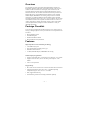
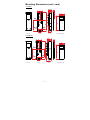
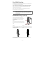
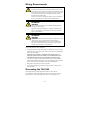
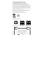
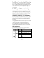
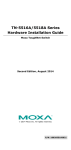
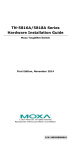
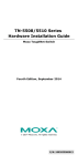
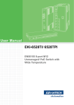
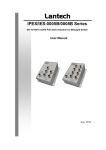
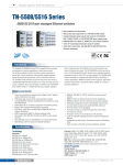
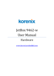
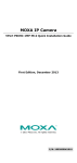
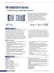
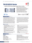
Moxa ToughNet Switch
TN-5308 Series
Layer 2 M12 unmanaged Ethernet switches
Hardware Installation Guide
First Edition, May 2009
© 2009 Moxa Inc. All rights reserved.
Reproduction without permission is prohibited.
P/N: 1802053080010
Overview
The ToughNet TN-5308 series M12 unmanaged Ethernet switches are
designed for industrial applications in harsh environments. The TN series
switches use M12 connectors to ensure tight, robust connections, and
guarantee reliable operation against environmental disturbances, such as
vibration and shock. The TN-5308 series Ethernet switches provide 8 Fast
Ethernet M12 ports, support IEEE 802.3/802.3u/802/3x with 10/100M,
full/half-duplex, MDI/MDI-X auto-sensing, and provide an economical
solution for your industrial Ethernet network. Models with an extended
operating temperature range of -40 to 75°C are also available. The TN-5308
series Ethernet switches are compliant with EN50155/50121-3-2/50121-4
(railway applications), NEMA TS2 (traffic control systems), and e-Mark
(vehicles) requirements, making the switches suitable for a variety of
industrial applications.
Package Checklist
Your TN-5308 is shipped with the following items. If any of these items is
missing or damaged, please contact your customer service representative for
assistance.
y Moxa ToughNet Switch
y Panel Mounting Kit
y Hardware Installation Guide
y Moxa Product Warranty Statement
Features
High Performance Network Switching Technology
y 8 10/100BaseT(X) ports
y Store and Forward switching process type
y IEEE 802.3/802.3u/802.3x
y 10/100M, Full/Half-Duplex, MDI/MDIX auto-sensing
Industrial-Specific Applications
y Support 12/24/36/48 VDC (7 to 60 VDC) power input for “-LV” models
y Support 72/96/110 VDC (50.4 to 154 VDC) power input for “-MV”
models
y Active circuit protection
Rugged Design
y M12 / M23 circular connectors for vibration-resistant robust connections
y Operating temperature range of 0 to 60°C, or extended operating
temperature range of -40 to 75°C for “-T” models
y IP40, rugged metal housing
y Panel mounting or DIN-rail mounting installation capability
— 1 —
TN-5308-LV Panel Layouts
Front Panel View
Rear Panel View
1
2
3
11
4
4
5
6
7
8
4
9
10
4
7
4
1.
2.
TP port’s 10/100 Mbps LED
10/100BaseT(X) port
(female 4-pin shielded M12 connector with D coding)
3.
4.
Port label
Screw holes for panel mounting kit or DIN rail mounting kit
(there are 3 holes: top middle, bottom left, and bottom right)
5.
6.
Power input LED
Power input port
(male 5-pin shielded M12 connector with A coding)
7.
Grounding screw
8.
Power input port pin assignment
9.
Model name
10. TP port pin assignment
11. Model label
— 2 —
4
TN-5308-MV Panel Layouts
Front Panel View
Rear Panel View
1
2
3
11
4
4
5
6
9
7
8
4
7
10
4
4
1.
TP port’s 10/100 Mbps LED
2.
10/100BaseT(X) port
(female 4-pin shielded M12 connector with D coding)
3.
4.
Port label
Screw holes for panel mounting kit or DIN rail mounting kit
(there are 3 holes: top middle, bottom left, and bottom right)
5.
6.
Power input LED
Power input port
(male 5-pin shielded M23 connector with A coding)
7.
Grounding screw
8.
Power input port pin assignment
9.
Model name
10. TP port pin assignment
11. Model label
— 3 —
4
Mounting Dimensions (unit = mm)
TN-5308-LV
Rear View
Front View
Side View
DIN-Rail Mounting Kit
TN-5308-MV
Rear View
Front View
Side View
— 4 —
DIN-Rail Mounting Kit
Panel/Wall Mounting
Mounting the TN-5308-LV/MV on the wall requires 3 screws. Please use the
3 screws packed in the panel mounting kit.
STEP 1: Prepare the 3 screw holes on the wall according to the positions of
the 3 screw holes on the switch shown on the mounting dimension diagram.
STEP 2: Use one screw to go through the top-middle screw hole on the
switch and screw it into the wall.
STEP 3: Screw in the remaining 2 screws through the bottom-left and
bottom-right holes on the switch to the wall.
NOTE
The screw lengths of TN-5308-LV and TN-5308-MV are
different. TN-5308-LV uses M3 * 30 mm screws. TN-5308-MV
uses M3 * 40 mm screws. Please use the screws packed in the
panel mounting kit.
DIN-Rail Mounting (optional)
With the optional DIN-Rail mounting kit
DK-TN-5308 (must be purchased separately),
you can mount the TN-5308-LV/MV on a
35mm DIN-Rail.
STEP 1:
Fix the DIN-Rail attachment plate onto the rear
panel of the switch as shown in the figure at the
right.
STEP 2:
STEP 3:
Position the TN-5308-LV/MV on the Swing the switch down fully onto the
DIN-Rail, tilting to hook clamps over DIN-Rail until both clamps completely
the top edge of the rail.
latch.
metal
spring
metal
spring
DIN-Rail
DIN-Rail
To remove the Moxa ToughNet Switch from the DIN-Rail, simply reverse
Steps 2 and 3 above.
— 5 —
Wiring Requirements
WARNING
Turn the power off before disconnecting modules or wires. The
correct power supply voltage is listed on the product label. Check
the voltage of your power source to make sure you are using the
correct voltage. Do NOT use a voltage greater than what is
specified on the product label.
These devices must be supplied by a SELV source as defined in
the Low Voltage Directive 2006/95/EC and 2004/108/EC.
ATTENTION
Safety First!
Be sure to disconnect the power cord before installing and/or
wiring your Moxa switch.
This device has UL508 approval. Use copper conductors only,
60/75°C, and tighten to 4.5 pound-inches. For use in pollution
degree 2 environments.
ATTENTION
Safety First!
Calculate the maximum possible current in each power wire and
common wire. Observe all electrical codes dictating the
maximum current allowable for each wire size. If the current
goes above the maximum ratings, the wiring could overheat,
causing serious damage to your equipment.
Please read and follow these guidelines:
y Use separate paths to route wiring for power and devices. If power wiring
and device wiring paths must cross, make sure the wires are perpendicular
at the intersection point.
NOTE: Do not run signal or communications wiring and power
wiring through the same wire conduit. To avoid interference, wires
with different signal characteristics should be routed separately.
y You can use the type of signal transmitted through a wire to determine
which wires should be kept separate. The rule of thumb is that wiring that
shares similar electrical characteristics can be bundled together.
y Keep input wiring and output wiring separated.
y It is strongly advised that you label wiring for all devices in the system
when necessary.
Grounding the TN-5308
Grounding and wire routing help limit the effects of noise due to
electromagnetic interference (EMI). Run the ground connection from the
grounding screw to the grounding surface prior to connecting devices.
— 6 —
ATTENTION
This product is intended to be mounted to a well-grounded
mounting surface such as a metal panel.
Connecting the Power Supply
The M12/M23 A-coded 5-pin male connector on the TN-5308-LV/MV front
panel is used for the DC power input. You have to prepare a power cord with
M12/M23 A-coded 5-pin female connector to connect the switch to the DC
power input.
Pinouts for the power input port on the TN-5308-LV
N.C. : Not connected
Pinouts for the power input port on the TN-5308-MV
STEP 1: Plug your power cord connector to the power input port of the
TN-5308 switch.
STEP 2: Screw the nut on your power cord connector to the power input
connector on the switch to ensure a tight connection.
ATTENTION
Before connecting the TN-5308 to the DC power input, make
sure the DC power source voltage is stable.
— 7 —
Connecting the Data Lines
10/100BaseT(X) Ethernet Port Connection
All TN-5308 models have 8 10/100BaseT(X) Ethernet ports (4-pin shielded
M12 connectors with D coding). The 10/100TX ports located on the
TN-5308’s front panel are used to connect to Ethernet-enabled devices. Most
users configure these ports for Auto MDI/MDI-X mode, in which case the
port’s pinouts are adjusted automatically depending on the type of Ethernet
cable used (straight-through or cross-over), and the type of device (NIC-type
or HUB/Switch-type) connected to the port.
In what follows, we give pinouts for both MDI (NIC-type) ports and MDI-X
(HUB/Switch-type) ports. We also give cable wiring diagrams for
straight-through and cross-over Ethernet cables.
Pinouts for the 10/100BaseT(X) Ports on the TN-5308
Housing: shield
Pinouts for the RJ45 (8-pin) Port
RJ45 (8-Pin)
1
8
MDI Port Pinouts
Pin
1
2
3
6
MDI-X Port Pinouts
Signal
Tx +
Tx Rx +
Rx -
Pin
1
2
3
6
Signal
Rx +
Rx Tx +
Tx -
M12 (4-pin, M) to M12 (4-pin, M) Cross-Over Cable Wiring
Cross-Over Cable Wiring
Tx+
Rx+
TxRx-
1
2
3
4
1
2
3
4
— 8 —
Tx+
Rx+
TxRx-
M12 (4-pin, M) to M12 (4-pin, M) Straight-Trough Cable Wiring
Straight-through Cable Wiring
Tx+
Rx+
TxRx-
1
2
3
4
1
2
3
4
Rx+
Tx+
RxTx-
1
2
3
6
Tx+
TxRx+
Rx-
M12 (4-pin, M) to RJ45 (8-pin) Cross-Over Cable Wiring
Cross-Over Cable Wiring
Tx+
Rx+
TxRx-
1
2
3
4
M12 (4-pin, M) to RJ45 (8-pin) Straight-Trough Cable Wiring
Straight-through Cable Wiring
Tx+
Rx+
TxRx-
1
2
3
4
1
2
3
6
Rx+
RxTx+
Tx-
Auto MDI/MDI-X Connection
The Auto MDI/MDI-X function allows users to connect TN-5308’s
10/100BaseTX ports to any kind of Ethernet device, without needing to pay
attention to the type of Ethernet cable being used for the connection. This
means that you can use either a straight-through cable or cross-over cable to
connect the TN-5308 to Ethernet devices.
— 9 —
Dual Speed Functionality & Switching
The TN-5308’s 10/100 Mbps switched M12 ports auto negotiate with the
connected device to use the fastest data transmission rate supported by both
devices. All of Moxa’s ToughNet switches are plug-and-play devices, so that
software configuration is not required. The half/full duplex mode for the
switched M12 ports is user dependent and changes (by auto-negotiation) to
full or half duplex, depending on which transmission speed is supported by
the attached device.
Switching and Address Learning
The TN-5308 has a MAC address table that can hold up to 1000 node
addresses, which makes it suitable for use with large networks. The address
tables are self-learning, so that as nodes are added or removed, or moved
from one segment to another, the TN-5308 automatically keeps up with new
node locations. An address-aging algorithm causes the least-used addresses to
be deleted in favor of newer, more frequently used addresses. To reset the
address buffer, power down the unit and then power it back up.
Switching, Filtering, and Forwarding
Each time a packet arrives at one of the switched ports, a decision is made to
filter or forward the packet. Packets with source and destination addresses
belonging to the same port segment will be filtered, constraining those
packets to one port, and relieving the rest of the network from the need to
process them.
A packet with destination address on another port segment will be forwarded
to the appropriate port, and will not be sent to the other ports where it is not
needed. Packets that are used in maintaining the operation of the network
(such as the occasional multi-cast packet) are forwarded to all ports.
The TN-5308 operates in the store-and-forward switching mode, which
eliminates bad packets and enables peak performance to be achieved when
there is heavy traffic on the network.
LED Indicators
Several LED indicators are located on the TN-5308’s front panel. The
function of each LED is described in the table below.
LED
Color
PWR
AMBER
State
On
Off
TP
(10M)
AMBER
TP
(100M)
GREEN
On
Blinking
Off
On
Blinking
Off
Description
Power is being supplied to the power
input.
Power is not being supplied to the
power input.
TP port’s 10 Mbps link is active.
Data is being transmitted at 10 Mbps
TP port’s 10 Mbps link is inactive.
TP port’s 100 Mbps link is active
Data is being transmitted at 100
Mbps.
TP port’s 100 Mbps link is inactive.
— 10 —
Auto-Negotiation and Speed Sensing
All of the TN-5308’s Ethernet ports independently support auto-negotiation
for speeds in the 10BaseT and 100BaseTX modes, with operation according
to the IEEE 802.3u standard. This means that some nodes could be operating
at 10 Mbps, while at the same time, other nodes are operating at 100 Mbps.
Auto-negotiation takes place when an M12 cable connection is made, and
then each time a LINK is enabled. The TN-5308 advertises its capability for
using either 10 Mbps or 100 Mbps transmission speeds, with the device at the
other end of the cable expected to advertise in the same way. Depending on
what type of device is connected, this will result in agreement to operate at a
speed of either 10 Mbps or 100 Mbps.
If a TN-5308’s Ethernet port is connected to a non-negotiating device, it will
default to 10 Mbps speed and half-duplex mode, as required by the IEEE
802.3u standard.
Specifications
Technology
Standards
IEEE 802.3 for 10BaseT
IEEE 802.3u for 100BaseT(X)
IEEE 802.3x for Flow Control
Processing Type
Store and Forward
Flow Control
IEEE802.3x flow control, back pressure flow
control
Interface
M12 Ports
10/100BaseT(X) auto negotiation speed, F/H duplex
mode and auto MDI/MDI-X connection
LED Indicators
PWR, 10/100M
Power Requirements
Input Voltage
TN-5308-LV: 12/24/36/48 VDC (7 to 60 VDC)
TN-5308-MV: 72/96/110 VDC (50.4 to 154 VDC)
Input Current
TN-5308-LV: 0.19A @ 12 VDC, 0.10A @ 24 VDC,
0.054A @ 48 VDC
TN-5308-MV: 0.033A @ 72 VDC, 0.024A @ 96
VDC, 0.021A @ 110 VDC
Connection
TN-5308-LV: M12 A-coding, 5-pin male connector
TN-5308-MV: M23 A-coding, 5-pin male connector
Overload Current
Protection
Present
Reverse Polarity
Protection
Present
Physical Characteristics
Housing
Metal, IP40 protection
Dimensions (W × H × D) TN-5308-LV: 60 x 216.6 x 36.1 mm
(2.36 x 8.53 x 1.42 in)
TN-5308-MV: 60 x 216.6 x 53.7 mm
(2.36 x 8.53 x 2.11 in)
— 11 —
Weight
TN-5308-LV: 485 g
TN-5308-MV: 685 g
Installation
Panel mounting, DIN-Rail mounting (with optional
kit)
Environmental Limits
Operating Temperature
Standard Models: 0 to 60°C (32 to 140°F)
Wide Temp. Models: -40 to 75°C (-40 to 167°F)
Storage Temperature
-40 to 85°C (-40 to 185°F)
Operating Humidity
5 to 95% (non-condensing)
Regulatory Approvals
Safety
UL508 (Pending)
Rail Traffic
EN50155 (Environmental, Pending), EN50121-3-2
(Pending), EN50121-4 (Pending)
Traffic Control
NEMA TS2 (Pending), e-Mark (Pending)
EMI
FCC Part 15, CISPR (EN55022) class A
EMS
EN61000-4-2 (ESD), level 3
EN61000-4-3 (RS), level 4
EN61000-4-4 (EFT), level 3
EN61000-4-5 (Surge), level 3
EN61000-4-6 (CS), level 3
EN61000-4-8
EN61000-4-11
EN61000-4-12
Shock
IEC61373
Freefall
IEC60068-2-32
Vibration
IEC61373
Note: Please check Moxa’s website for the most up-to-date certification
status.
WARRANTY
5 years
Details: See www.moxa.com/warranty
Technical Support Contact Information
www.moxa.com/support
Moxa Americas:
Toll-free: 1-888-669-2872
Tel:
+1-714-528-6777
Fax:
+1-714-528-6778
Moxa China (Shanghai office):
Toll-free: 800-820-5036
Tel:
+86-21-5258-9955
Fax:
+86-10-6872-3958
Moxa Europe:
Tel:
+49-89-3 70 03 99-0
Fax:
+49-89-3 70 03 99-99
Moxa Asia-Pacific:
Tel:
+886-2-8919-1230
Fax:
+886-2-8919-1231
— 12 —