1
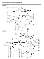
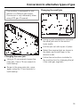
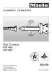
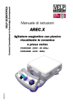
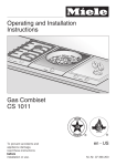
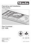
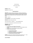
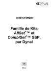
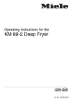
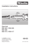
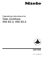
Operating instructions for
Gas cooktops
KM 83-2, KM 93-2
CANADIAN GAS ASSOCIATION
R
APROVED
]ö
M.-Nr. 03 998 090
Description of the appliance
Description of the appliance
KM 83-2
5
4
6
3
7
8
2
9
1
10
12
11
KM 93-2
4
3
5
6
7
2
8
1
9
10
11
2
15 14
13
12
Description of the appliance
Description of the appliance
KM 83-2
b Control panel
c Normal burner
n Control for the rear right burner
o Control for the rear left burner
p Control for the front left burner
d Fast burner
e Pan support
f Ring support for the Normal burner
g Burner cap
h Ignitor
i Ignition safety control
j Burner head
k Cable for connection
to electrical supply approx. 3.6 ft
(1.10 m) long.
l Control for front burner
m Control for rear burner
KM 93-2
b Control panel
c Normal burner
d Pan support
e Ring support for the normal burner
f Burner cap
g Ignitor
h Ignition safety control
i Burner head
j Fast burner
k Normal burner
l Cable for connection
Data plate
Because the data plate is no longer
visible once the appliance has been installed, a 2nd data plate is supplied
which should be placed into the space
provided on page 15 of these instructions.
Special accessories
Special accessories are available from
your Miele Dealer or from the Miele
Parts Department.
Stainless steel cover EA 80
A stainless steel cover is available for
the KM 83-2 cooktop. Check availability in each country.
For installation of the cover, a minimum
distance of 20" (510 mm) is required between the countertop and wall cabinets.
Note:
The pan support must be removed before lowering the stainless steel cover
(EA80).
Do not install the DA 8-2 directly
next to the gas hob.
to electrical supply, approx. 3.6 ft
(1.10 m) long
m Control for the front right burner
3
For your safety
For your safety
WARNING: If the information in
this manual is not followed
exactly, a fire or explosion may
result causing property damage,
personal injury or death.
Do not store or use gasoline or other
flammable vapors and liquids in the
vicinity of this or any other appliance.
WHAT TO DO IF YOU SMELL GAS
– Do not try to light any appliance.
– Do not touch any electrical
switch; do not use any phone in
your building.
– Immediately call your gas supplier from a neighbor’s phone.
Follow the gas supplier’s instructions.
– If you cannot reach your gas supplier, call the fire department.
Installation and service must be
performed by a qualified installer,
service agency or the gas supplier.
4
Note to the installer (CDN and USA)
LEAVE THESE INSTRUCTIONS
WITH THE CONSUMER.
The appliance and its individual shutoff
valve must be disconnected from the gas
supply piping system during any pressure
testing of that system at test pressures in
excess of 1/2 psi (3.5 kPa).
The appliance must be isolated from the
gas supply piping system by closing its
individual manual shutoff valve during
any pressure testing of the gas supply
piping system at test pressures equal to
or less than 1/2 psi (3.5 kPa).
For Canada only:
The minimum supply pressure for
checking the regulator setting shall be
5 inches water column (1246 Pa),
which is 1 inch water column (249 Pa)
above the manifold pressure of 4 inches water column (996 Pa).
Help protect our environment
Help protect our environment
Disposal of packaging
The transport and protective packing is
mostly manufactured from the following
re-usable materials:
– Corrugated paper / card board mostly from recycled materials.
– Polyethylene foil (PE) partly from secondary raw materials.
Rather than throwing these materials
away, please take them to the nearest
recycling center for specific waste.
Disposal of your old machine
Old machines contain materials which
can be recycled. Please contact your
local recycling center or scrap merchant about potential recycling programs, before disposing of the appliance.
Read the notes on page 8 before disposing of the appliance.
5
Contents
Contents
Description of the appliance . . . . . . . . . . . . . . . . . . . . . . . . . . . . . . . . . . . . . . . . . 2
For your safety . . . . . . . . . . . . . . . . . . . . . . . . . . . . . . . . . . . . . . . . . . . . . . . . . . . . 4
Help protect our environment . . . . . . . . . . . . . . . . . . . . . . . . . . . . . . . . . . . . . . . . 5
Warning and Safety Instructions . . . . . . . . . . . . . . . . . . . . . . . . . . . . . . . . . . . . . 7
Using the cooktop
Burner controls. . . . . . . . . . . . . . . . . . . . . . . . . . . . . . . . . . . . . . . . . . . . . . . . . . . .
Instructions for using the gas burners . . . . . . . . . . . . . . . . . . . . . . . . . . . . . . . . . .
Power outage . . . . . . . . . . . . . . . . . . . . . . . . . . . . . . . . . . . . . . . . . . . . . . . . . . . . .
Suitable pans . . . . . . . . . . . . . . . . . . . . . . . . . . . . . . . . . . . . . . . . . . . . . . . . . . . . .
10
10
11
12
Cleaning and care . . . . . . . . . . . . . . . . . . . . . . . . . . . . . . . . . . . . . . . . . . . . . . . . 13
Problem solving guide. . . . . . . . . . . . . . . . . . . . . . . . . . . . . . . . . . . . . . . . . . . . . 15
After Sales Service. . . . . . . . . . . . . . . . . . . . . . . . . . . . . . . . . . . . . . . . . . . . . . . . 16
Electrical connection . . . . . . . . . . . . . . . . . . . . . . . . . . . . . . . . . . . . . . . . . . . . . . 17
Gas connection . . . . . . . . . . . . . . . . . . . . . . . . . . . . . . . . . . . . . . . . . . . . . . . . . . 18
Appliance dimensions . . . . . . . . . . . . . . . . . . . . . . . . . . . . . . . . . . . . . . . . . . . . . 19
Installation instructions. . . . . . . . . . . . . . . . . . . . . . . . . . . . . . . . . . . . . . . . . . . . 21
Conversion to alternative types of gas . . . . . . . . . . . . . . . . . . . . . . . . . . . . . . . 24
6
Warning and Safety Instructions
Warning and Safety Instructions
Important safety instructions
Warning:
When using your cooktop, follow
basic safety precautions including
the following:
Read all instructions before using
the cooktop.
Use the cooktop only for its intended purpose.
Do not use the cooktop unless all
parts are properly in place according to the installation and operating instructions.
Before servicing, disconnect the
power supply by removing the fuse
or tripping the circuit breaker.
The electrical safety of this appliance can only be guaranteed
when continuity is complete between
the appliance and an effective grounding system.
It is imperative that this basic safety requirement is met. If there is any doubt,
have the electrical system of the house
checked by a qualified electrician. The
manufacturer cannot be held responsible for damage caused by the lack or
inadequacy of an effective grounding
system.
Store all toys away from the cooktop to prevent injury to curious or
playful children.
Please remember that, in use, burners and pot racks become hot.
Ensure that children do not touch them.
Do not let cooking grease or other
flammable materials accumulate
on the cooktop.
Allow sufficient time for the burners
to cool before touching or exposing surface areas to flammable materials.
Always cook pork thoroughly to ensure that, in the event of trichina,
all bacteria will be killed and the meat
is safe to eat.
If high settings are used, remain
near the cooktop and watch for
splattering grease or boiling over which
may cause smoking.
Never use wet potholders.
Use only cookware suitable for
range-top service. Unsuitable
cookware may break due to sudden
temperature changes.
Do not connect the appliance to the
main electrical supply using an extension cord. Extension cords do not guarantee the required safety of the appliance.
Never use the cooktop to warm or
heat the room.
7
Warning and Safety Instructions
Warning and Safety Instructions
Always position the handle of the
cookware toward the center of the
range to minimize burns and spillage.
Before removing pots and pans,
be sure to turn the cooktop ”OFF“.
Always heat oil slowly so it doesn’t
bubble over.
When frying foods, make sure that
the food is as dry as possible to
prevent moisture from causing hot oil to
bubble over.
When shallow or deep frying, do
not overfill the pan with oil.
Do not use a steam-cleaning appliance to clean the gas cooktop.
The steam could penetrate to electrical
components and cause a short circuit.
SAVE THESE INSTRUCTIONS!
8
Important notes for the installer
The minimum clearances:
between adjacent cabinets and fixtures – 4" (100 mm).
between the appliance and rear wall
– 2 1/4" (55 mm).
between the appliance and overhead cabinets and fixtures
– 30" (760 mm)
between the appliance and front
edge of countertop – 2 1/4" (55 mm)
between cabinets and the extended
cooking surface – 18" (460 mm)
Backsplashes and/or side walls
must be heat resistant.
Leave these instructions with the
consumer.
Warning and Safety Instructions
Warning and Safety instructions
Important notes for the user
Installation and maintenance
should only be performed by a
qualified technician.
For safety reasons, this cooktop
should only be installed as a builtin appliance.
Please remember that the cooktop
may become hot, not only around
the burner, but also around the control
panel. Ensure that small children do not
touch the cooktop when it is being
used.
Never leave the cooktop unattended when cooking with oil or
fat. Overheated oil and fat can catch
fire.
When cooking or boiling in large
pots or pans, ensure that there is a
minimum distance of 2" (50 mm) between the pot and a heat-sensitive
countertop. After combustion, the hot
gases flow outwards under the base of
the pot and may consequently burn the
edge of the countertop if it is not heat
resistant.
Make sure that there is a minimum
distance of 5/8" (15 mm) between
the pot or pan and the control panel.
Never place a pot on the control panel.
When using an electric outlet near
the cooktop, care should be taken
to ensure that the cable of the electrical
appliance does not fall into the flames.
When using a vent hood over a
gas cooktop, make sure that any lit
burners are always covered with a pot
or frying pan. Otherwise, parts of the
vent hood could be damaged by the
heat and / or flames.
Note and correct any potential hazards that may exist in regards to
overhead cabinets.
Do not use the cooktop for space
heating.
Keep these instructions in a safe
place and pass them on to any future
user.
Disposal of an old appliance
Before disposing of an old appliance, ensure that disconnection
from the gas supply is made by a qualified technician. Turn off at the main
power source, and disconnect and
remove the appliance cable. This is intended to prevent the discarded appliance from becoming a hazard.
Text highlighted in boxes is of particular importance and should be
read in conjunction with the Warning and Safety instructions.
9
Using the cooktop
Using the cooktop
Before using for the first time thoroughly read the “Warning and
Safety instructions”.
Burner controls
The burner controls can only be
turned counter-clockwise as far as
the small flame symbol, otherwise
the controls could be damaged.
Each burner is equipped with an ignition safety device. If a gas flame goes
out, for example if food has boiled over
or if there was a sudden draft, the ignition safety control cuts off the supply of
gas.
Instructions for using the gas
burners
Place the pan on the pan support.
The flame strength can selected as follows:
X Gas turned off
& High flame
/ Low flame
The gas flame is lit by electriconic ignition. When the burner control is
pressed, a spark passes from the ignitor to the burner and ignites the gas to
give a flame.
10
A ring support (trivet) is supplied with
the cooktop. It is designed to rest on
the pan support when using small
pans.
The ring support should only be used
on a normal (front) burner with a low
flame.
It should only be used with pans having a diameter of less than 4" (10 cm).
Ignoring this advice could result in
damage to the ring support enamel.
Using the cooktop
Using the cooktop
Press in the correct control knob and
turn counter-clockwise to the high
setting (large flame symbol).
When the flame ignites, keep the button pressed in for 5-10 seconds, and
then press down firmly once more
before letting go.
If the flame goes out, repeat the procedure, keeping the control knob pressed
in for a few extra seconds.
Turn the control knob to a low setting to
prevent food from boiling over or burning.
To shut the burner off, turn the control knob clockwise to the “X“ position.
The flame will go out.
Power outage
If there is an interruption to the electrical supply, the gas can be ignited with
a match.
Press in and turn the burner control
counter-clockwise to the highest setting, (large flame).
With the control knob pressed in,
ignite the gas at the burner with a
match.
Keep the control knob pressed in for
an additional 5-10 seconds, then
press down firmly once again before
letting go.
Important:
If, after several attempts the gas still
does not ignite, check whether the
knobs of the burner cap are correctly
positioned in the notches of the burner
head.
When using the burners :
Make certain that there is a minimum
distance of 2" (50 mm) between the
pan and heat-sensitive countertops
or surroundings.
Turn the control knob to:
– the high setting for boiling or
searing food or;
– the low setting for continued cooking
and for keeping food warm.
After combustion, the hot gases
flow outwards under the base of the
pan, and may consequently burn
the edge of the countertop or surroundings they are not heat resistant.
11
Using the cooktop
Using the cooktop
Make certain that there is a minimum
distance of 5/8" (15 mm) between
the pan and the control panel.
Never place a pan on the control
panel.
The outer part of the gas flame is much
hotter than the center. Therefore the
tips of the flame should be in contact
with the base of the pan and not
spread out to the sides. Flames which
spread out to the sides of the pan
merely warm up the air in the room.
Thick pan bases lessen the risk of
food overheating, as better heat distribution is possible.
Size of pans
Using a small pan on the large burner
does not make cooking faster, but simply results in wasteful gas consumption. The correct procedure is to cook
with small pans on the normal burner
and large ones on the large burner.
small pans = small burners
large pans = large burners
Suitable pans
Material
Most pans can be used for cooking on
gas.
Pan base
Pan bases do not need to be even for
gas cooking, in contrast to those used
on electric burners. Through the
spreading action of the flame, heat
reaches all parts of the base.
Thin pans conduct heat to the food inside more quickly than thick ones.
Since heat is never evenly distributed
over the pan base, there is a danger
that food may overheat in places.
Therefore, when using saucepans with
thin bases, stir the food more often.
12
Wide, flat pans are more suitable than
narrow, tall ones, since they heat up
more quickly.
Lids
Less heat is lost by cooking in a
covered pot.
Cleaning and care
Cleaning and care
If of a pot boils over, clean the burner
and the cooktop surface immediately,
to prevent the substance from burning
on.
Install the burner cap correctly on the
burner head after cleaning.
Burners
The burners can be dismantled for
cleaning when cold.
Burner caps
The burner caps can be cleaned with a
solution of dishwashing liquid.
Do not use any caustic cleaners,
scouring powders, knives or hard
brushes, as these will scratch.
With time and use, the surface of the
burner caps will attain a matt finish.
Burner head
These can be cleaned with a damp
cloth or with a chrome / stainless steel
cleaner.
Electronic ignition
The ignitors must always be dry,
otherwise they will not spark.
From time to time, the ignitors should
be wiped with a damp cloth and dried
with a clean cloth.
Important: The burners must be correctly installed before they are lit,
otherwise the ignitor could be damaged.
Pan supports, ring support
Caution: the pan supports and the
ring support become hot during use.
The pan supports can be removed for
cleaning:
Lift the support at the back and pull
it out of the holders at the front.
13
Cleaning and care
Cleaning and care
The pan supports and ring support can
be cleaned in a hot solution of dishwashing liquid.
Never use scouring agents as these
could scratch the surface.
Dry with a soft cloth.
Cooktop surface
Do not allow liquids or foods containing salt or sugar to spill onto the
cooktop. Should this happen, wipe
up any spills immediately, otherwise
discoloration could occur.
Remove dust, oils and fats, spills of
foods and condensed water from pots
and pans immediately to prevent them
from drying on. Dried on food residues
are easier to remove if they are first softened with warm water.
Clean the cooktop surface using hot
water with a little dishwashing liquid.
Do not use cleaning agents containing acids. A cleaning agent for stainless steel can be used on the stainless steel cooktop surface.
14
Control panel / Control knobs
Do not use any scouring agents or
pads on the knobs or control panel.
Clean the cooktop controls and the control panel with hot water and a little dishwashing liquid.
After application, rub dry with a clean
cloth.
Problem solving guide
Problem solving guide
Repairs to the gas and electrical
components of this appliance
should only be performed by a
trained technician. Repairs by unauthorized personnel could be dangerous.
Some minor problems can be resolved
as follows:
What to do if . . .
. . . the burners do not ignite after
several attempts?
. . . the gas flame goes out after
being lit?
Check whether the burner cap is correctly positioned on the burner head.
. . . the electric spark ignition for the
gas burners no longer works?
Check whether food residues or
cleaning agent have collected between the ignitor and the burner.
Clean these carefully. Do not let the
ignitor get wet.
Check whether:
the burner cap is correctly positioned on the burner head.
the gas supply valve is turned on.
a main fuse has blown. In this case
call an electrician or the Miele Service Dept.
A match can be used to light the burner.
See page 10.
. . . the shape and color of the flame
are different than usual?
Check whether the burner cap is correctly positioned on the burner head.
15
After Sales Service
After Sales Service
In the event problems arise that you
cannot correct yourself, or if the appliance is under warranty, please contact:
Your Miele Dealer
or
The Miele Service Department
The address of the nearest Service
Department is given on the back page.
When contacting the Service Department, please quote the Model and Serial No. of the appliance, both which
can be found on the data plate.
Space for enclosed data plate
16
Electrical connection
Electrical connection
The automatic ignition requires connection to a 120 VAC, 60 Hz power supply.
Fuse rating is 6 A.
These appliances are factory equipped
with a power supply cord with a
molded three-prong plug – ready for
connection to an electrically grounded
socket which complies with your local
electrical codes or with the
National Electical Code ANSI/NFPA
No. 70-1481 for the USA
or
Canadian Electrical Code Part I for
Canada (CSA Standard C 22.1).
Ensure that the receptacle is positioned
so that it is easily accessible after the
appliance is built in.
WARNING:
THIS APPLIANCE MUST BE
GROUNDED.
Do not cut or remove the grounding
prong from this plug.
17
Gas connection
Gas connection
This appliance must be installed
with a separate shut-off valve and a
gas pressure regulator (included).
Both shut-off valve and pressure
regulator must be easily accessible
to the consumer.
This appliance and its individual
shut-off valve must be disconnected from the gas supply system
during any pressure testing of that
system.
Pressure regulator
A pressure regulator convertible from
Natural to LP Gas is included with this
appliance.
Conversion is carried out by inverting
the regulator cap marked "NAT"/"LP". If
"NAT" is visible then the regulator is set
for Natural and if "LP" is visible then setting is for Liquefied Petroleum Gas (Propane).
Nominal rating for all types of gas on
the high setting
For USA only
The gas connection must be made
in accordance with local codes, or
in absence of local codes, with the
National Fuel Gas Code,
ANSI Z 223.1-1980.
Gas Pressures for USA
Max. Supply Pressure: 1/2 PSI
Manifold pressure:
– Natural gas – 4" water column
– Propane gas – 10" water column
For CDN only
The gas connection must be made
in accordance with local codes, or
in absence of local codes, with the
current CAN/CGA B 149.1 and .2
Inst.
Gas Pressures for CDN
Manifold pressure:
– Natural gas 4" water column
– Propane gas 10" water column
18
Normal burner
Fast burner
kW
Btu/hr
1.65
2.70
5630
9212
Nominal rating on the low setting
Type of gas
kW
Btu/hr
Normal burner
Natural gas
LP gas
0.26
0.26
887
887
Fast burner
Natural gas
LP gas
0.45
0.54
1535
1842
Appliance dimensions
Appliance dimensions
KM 83-2
KM 93-2
Measurement Conversion Table
mm
inches
490
19 5/16
265
10 7/16
560
22 1/16
510
20 1/16
288
11 3/8
580
22 13/16
55
2 3/16
19
Appliance dimensions
Appliance dimensions
KM 83-2
KM 93-2
Gas connection:
Gas connection:
Measurement Conversion Table
20
mm
inches
30
1 3/16
323,5
12 3/4
Installation instructions
Installation instructions
The following minimum dimensions
must be observed:
– a distance of 4" (100 mm) from adjacent units if they are susceptible
to heat, otherwise some form of insulation must be installed.
– a distance of 30" (76 cm) between
the cooktop and any cabinet installed above it.
– a distance of 26" (65 cm) between
the cooktop and vent hood (or more
if building regulations require).
All backsplashes must be made of
heat resistant material. Please comply with the cabinet manufacturers
recommendations for safe distances.
If a drawer or shelf is installed
underneath the cooktop, make certain there is at least 3" (80 mm) between the base of the cooktop and
the upper edge of the drawer or
shelf.
The cooktop may be installed as shown
above.
Do not surround the cooktop with cabinetry, as this presents a fire hazard.
21
Installation instructions
Installation instructions
Depth
in
mm
Width *
(= Dimension B)
in mm
490
490
490
490
490
265
558
851
1144
1437
490
490
490
560
1143
1728
One 2 zone
+ one 4 zone
490
851
Two 2 zone
+ one 4 zone
490
1143
Three 2 zone
+ one 4 zone
490
1437
One 2 zone
+ two 4 zone
490
1436
Two 2 zone
+ two 4 zone
490
1729
2 zone Combiset
1 Combiset
2 Combisets
3 Combisets
4 Combisets
5 Combisets
4 zone Combiset
1 Combiset
2 Combisets
3 Combisets
Combination
2/ ˝
3 16
195/16˝
2/ ˝
3 16
Prepare the cooktop cut-out as illustrated.
Dimension ”B“ will vary depending
on how many combisets (cooktops)
are installed. The following chart
gives dimension ”B“ for a variety of
2 zone (ie KM 83-2) and 4 zone
(ie KM 93-2) combinations.
Extractor (e.g. DA 8-2)
For building in between two appliances:
- Dimension B increases by 90 mm.
For building in at the end of a combination:
- Dimension B increases by 98 mm.
* Width includes provision for V 98 spacer bar .
22
Installation instructions
Installation instructions
Depth
in
inch
Width *
(= Dimension B)
in inch
19-5/16"
19-5/16"
19-5/16"
19-5/16"
19-5/16"
10-7/16"
22"
33-1/2"
45-1/32"
56-9/16"
19-5/16"
19-5/16"
19-5/16"
22"
45"
68"
2 zone Combiset
1 Combiset
2 Combisets
3 Combisets
4 Combisets
5 Combisets
4 zone Combiset
1 Combiset
2 Combisets
3 Combisets
Combination
One 2 zone
+ one 4 zone
19-5/16"
33-1/2"
Two 2 zone
+ one 4 zone
19-5/16"
45"
Three 2 zone
+ one 4 zone
19-5/16"
56-9/16"
One 2 zone
+ two 4 zone
19-5/16"
56-1/2"
Two 2 zone
+ two 4 zone
19-5/16"
68-1/16"
Extractor (e.g. DA 8-2)
For building in between two appliances:
- Dimension B increases by 3 9/16".
For building in at the end of a combination:
- Dimension B increases by 3 7/8".
* Width includes provision for V 98 spacer bar.
Place the seal provided f under the
edge of the cooktop.
loosen
tighten
b Appliance
c Tensioning screw
d Clamp
e Countertop
f Seal
Turn the tensioning screws c
counter-clockwise until a resistance
is felt, then turn the clamp to the left.
Place the appliance into position,
turn the clamps and tighten the tensioning screws until the clamps
press into the countertop e.
Install the stainless steel lid, EA 80 (if
applicable). It is supplied with its
own installation instructions.
Connect the appliance to the electrical supply.
When installing several Combiset units,
a stainless steel spacer bar must be
placed between the units. It is supplied
with its own installation instructions.
23
Conversion to alternative types of gas
Conversion to alternative types of gas
When converting to alternative
types of gas, the main and small
jets of all burners must be changed.
Select the new jets following the table
below. The gas cooktop is supplied
equipped for natural gas; the appropriate gas jet kit for propane gas, LPG, is
also supplied with the appliance.
Reference table - jet sizes
Main jet
diameter
Natural gas
Normal burner
Fast burner
LP gas
Normal burner
Fast burner
24
Small jet
diameter
1.22 mm
0.048"
1.55 mm
0.061"
0.48 mm
0.019"
0.57 mm
0.023"
0.72 mm
0.028"
0.91 mm
0.036"
0.32 mm
0.013"
0.40 mm
0.016"
Conversion to LP Gas
Turn off the main gas supply (if the
appliance has already been installed) and turn off the main electrical supply.
Remove the pan supports and the
burner caps.
With a suitable tool, loosen and
remove the brass ring in each burner
head.
Remove the burner heads.
Pull the control knobs for the gas burners up and off.
Carefully raise the cooktop slightly at
the rear, pull forward and lift the control panel up. To avoid having to
remove the ground wire, stand the
control panel up against the wall behind the cooktop.
Conversion to alternative types of gas
Conversion to alternative types of gas
The cooktop is equipped for connection to a Natural gas supply.
Conversion is only necessary when
using LPG gas (Propane).
Changing the small jets
Using a small screwdriver, unscrew
the small jets next to the control
knob shafts.
Pull the jets out with a pair of pliers.
Select the required jets as shown in
the table, and install them in the
reverse order.
Changing the main jets
Using a 10 mm wrench loosen the
main jets. Use a 13 mm wrench to
hold backup.
Follow the instructions included in
the cooktop box for changing the jet
it the main gas regulator.
Screw in the new main jets, once
again using the 13 mm wrench to
hold backup.
25
Conversion to alternative types of gas
Conversion to alternative types of gas
Check the first intake of air.
Re-assemble the cooktop in the
reverse order.
b Securing screw
c Air sleeve
Gap X must be 13 mm / 1/2" for both
natural and liquid gas
If this is not the case, loosen the securing screw, re-position the air jet and
then tighten the securing screw.
Important note:
When reassembling, it is important
to ensure that the profile b of the
control panel grips the moulding c
on the lower casing.
When the top is reinstalled, the ignitor
and ignition safety control must be centered in their respective holes.
Put the burner heads on and secure
them with the brass rings. Replace the
burner caps.
26
Conversion to alternative types of gas
Conversion to alternative types of gas
After conversion
After converting the gas cooktop to
an alternative type of gas, place the
label supplied with the jet kit on the
data plate.
Check that the burner is assembled
correctly .
Turn on the gas supply.
Check that there are no leaks.
Turn on the electrical supply.
Light each of the burners in turn:
When set at “low”, the flame should
not go out, nor should it go out when
the control knob is quickly turned
from “high” to “low”.
When set at ”high“ the gas flame
must burn with a clearly visible center.
27
Alteration rights reserved /
CDN, USA - 01/0999