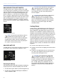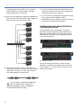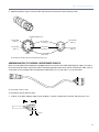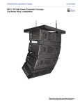
1
OPERATING INSTRUCTIONS INDUSTRIAL SERIES MM-10 Miniature Subwoofer MPS-488HP Power Supply Keep these important operating instructions. Check www.meyersound.com for updates. DECLARATION OF CONFORMITY ACCORDING TO ISO/IEC GUIDE 22 AND EN 45014 Manufacturer’s Name: Meyer Sound Laboratories Inc. Manufacturer’s Address: 2832 San Pablo Avenue Berkeley, CA 94702-2204, USA Declares that the product: Product Names: MM-10 Miniature Subwoofer MPS-488HP Power Supply Product Options: All Conforms to the following Product Specifications: Safety: EN 60065:2002 EMC: EN55103-1: 1997 emission1 EN55103-2: 1997 immunity2 This device also complies with EN 55103-1 & -2. Operation is subject to the following 2 conditions: (1) this device may not cause harmful interference, and (2) this device must accept any interference received, including interference that may cause undesired operation Supplementary Information: The product herewith complies with the requirements of the Low Voltage Directive (LVD) 2006/95/EC and the EMC Directive 2004/108/EC. Signature: Ms. Margie Garza Director of Quality Meyer Sound Laboratories Inc. Berkeley, California 94702 USA Issued August 18, 2011 European Contact: Your local Meyer Sound dealer or Meyer Sound Germany, GmbH. © 2010 Meyer Sound. All rights reserved. MM-10 Operating Instructions, PN 05.199.005.01 B The contents of this manual are furnished for informational purposes only, are subject to change without notice, and should not be construed as a commitment by Meyer Sound Laboratories Inc. Meyer Sound assumes no responsibility or liability for any errors or inaccuracies that may appear in this manual. Except as permitted by applicable copyright law, no part of this publication may be reproduced, stored in a retrieval system, or transmitted, in any form or by any means, electronic, mechanical, recording or otherwise, without prior written permission from Meyer Sound. MM-10, MM-4XP, MPS-488HP, MPS-488, and all alpha-numeric designations for Meyer Sound products and accessories are trademarks of Meyer Sound. Meyer Sound and the Meyer Sound wave logo are registered trademarks of Meyer Sound Laboratories Inc. (Reg. U.S. Pat. & Tm. Off.). All third-party trademarks mentioned herein are the property of their respective trademark holders. ii FEDERAL COMMUNICATIONS COMMISSION (FCC) STATEMENT This equipment has been tested and found to comply with the limits for a Class B digital device, pursuant to part 15 of the FCC Rules. These limits are designed to provide reasonable protection against harmful interference in a residential installation. This equipment generates, uses and can radiate radio frequency energy and, if not installed and used in accordance with the instructions, may cause harmful interference to radio communications. However, there is no guarantee that interference will not occur in a particular installation. If this equipment does cause harmful interference to radio or television reception, which can be determined by turning the equipment off and on, the user is encouraged to try to correct the interference by one or more of the following measures: —Reorient or relocate the receiving antenna. —Increase the separation between the equipment and receiver. —Connect the equipment into an outlet on a circuit different from that to which the receiver is connected. —Consult a Meyer Sound dealer or service representative for help. Properly shielded and grounded cables and connectors must be used in order to meet FCC emission limits. Proper cables and connectors are available from Meyer Sound authorized dealers. Meyer Sound is not responsible for any radio or television interference caused by unauthorized changes or modifications to this equipment. Unauthorized changes or modifications could void the user's authority to operate this equipment. This device complies with Part 15 of the FCC rules. Operation is subject to the following two conditions: (1) this device may not cause harmful interference, and (2) this device must accept any interference received, including interference that may cause undesired operation. INDUSTRY CANADA COMPLIANCE STATEMENT This Class B digital apparatus complies with Canadian ICES-003. AVIS DE CONFORMITÉ À LA RÉGLEMENTATION D'INDUSTRIE CANADA Cet appareil numérique de la classe B est conforme à la norme NMB-003 du Canada. iii SYMBOLS USED These symbols indicate important safety or operating features in this booklet and on the chassis: ! Dangerous voltages: risk of electric shock Important operating instructions Frame or chassis Protective earth ground Pour indiquer les risques résultant de tensions dangereuses Pour indequer important instructions Masse, châssis Terre de protection Warnung vor gefährlicher elektrischer Spannung Wichtige Betriebsanweisung oder Gebrauchsanleitung Rahmen oder Gehäuse Masse Schutzleiter Para indicar voltajes peligrosos Instrucciones importantes de funcionamiento y/o manteniento Armadura o chassis Tierra proteccionista IMPORTANT SAFETY INSTRUCTIONS 1. Read these instructions. 2. Keep these instructions. 3. Heed all warnings. 4. Follow all instructions. 11. Only use attachments/accessories specified by Meyer Sound. 12. If applicable, use only with the caster rails or rigging specified by Meyer Sound, or sold with the loudspeaker. Handles are for carrying only. 5. Do not use this loudspeaker near water. 6. Clean only with dry cloth. 7. Do not block any ventilation openings. Install in accordance with Meyer Sound’s installation instructions. 8. Do not install near any heat sources such as radiators, heat registers, stoves, or other apparatus that produce heat. 9. Do not defeat the safety purpose of the grounding-type plug. A grounding type plug has two blades and a third grounding prong. The third prong is provided for your safety. If the provided plug does not fit into your outlet, consult an electrician for replacement of the obsolete outlet. 10. Protect the power cord from being walked on or pinched, particularly at plugs, convenience receptacles, and the point where they exit from the loudspeaker. The AC mains plug or appliance coupler shall remain readily accessible for operation. ! CAUTION: Rigging should only be done by experienced professionals. 13. Unplug this loudspeaker during lightning storms or when unused for long periods of time. 14. Disconnect the mains plug before disconnecting the power cord from the loudspeaker. 15. Refer all servicing to qualified service personnel. Servicing is required when the loudspeaker has been damaged in any way, such as when the power-supply cord or plug has been damaged; liquid has been spilled or objects have fallen into the loudspeaker; rain or moisture has entered the loudspeaker; the loudspeaker has been dropped; or when for undetermined reasons the loudspeaker does not operate normally. CAUTION: To reduce the risk of electric shock, do not expose this loudspeaker to rain or moisture. Do not install the loudspeaker in wet or humid locations without using weather protection equipment from Meyer Sound. ! iv SAFETY SUMMARY English ■ ■ ■ To reduce the risk of electric shock, disconnect the loudspeaker from the AC mains before installing audio cable. Reconnect the power cord only after making all signal connections. Connect the loudspeaker to a two-pole, three-wire grounding mains receptacle. The receptacle must be connected to a fuse or circuit breaker. Connection to any other type of receptacle poses a shock hazard and may violate local electrical codes. Do not install the loudspeaker in wet or humid locations without using weather protection equipment from Meyer Sound. ■ Do not allow water or any foreign object to get inside the loudspeaker. Do not put objects containing liquid on or near the unit. ■ To reduce the risk of overheating the loudspeaker, avoid exposing it to direct sunlight. Do not install the unit near heat-emitting appliances, such as a room heater or stove. ■ ■ Ne pas installer l’haut-parleur dans un endroit où il y a de l’eau ou une humidité excessive. ■ Ne pas laisser de l’eau ou tout objet pénétrer dans l’haut-parleur. Ne pas placer de r´cipients contenant un liquide sur cet appareil, ni à proximité de celuici. ■ Pour éviter une surchauffe de l’hautparleur, conserver-la à l’abri du soleil. Ne pas installer à proximité d’appareils dégageant de la chaleur tels que radiateurs ou appareils de chauffage. ■ Ce haut-parleur contient des circuits haute tension présentant un danger. Ne jamais essayer de le démonter. Il n’y a aucun composant qui puisse être réparé par l’utilisateur. Toutes les réparations doivent être effectuées par du personnel qualifié et agréé par le constructeur. ■ ■ Um die Gefahr eines elektrischen Schlages auf ein Minimum zu reduzieren, den Lautsprecher vom Stromnetz trennen, bevor ggf. ein Audio-Schnittstellensignalkabel angeschlossen wird. Das Netzkabel erst nach Herstellung aller Signalverbindungen wieder einstecken. ■ Der Lautsprecher an eine geerdete zweipolige Dreiphasen-Netzsteckdose anschließen. Die Steckdose muß mit einem geeigneten Abzweigschutz (Sicherung oder Leistungsschalter) verbunden sein. Der Anschluß der unterbrechungsfreien Stromversorgung an einen anderen Steckdosentyp kann zu Stromschlägen führen und gegen die örtlichen Vorschriften verstoßen. This loudspeaker contains potentially hazardous voltages. Do not attempt to disassemble the unit. The unit contains no user-serviceable parts. Repairs should be performed only by factorytrained service personnel. Pour réduire le risque d’électrocution, débrancher la prise principale de l’hautparleur, avant d’installer le câble d’interface allant à l’audio. Ne rebrancher le bloc d’alimentation qu’après avoir effectué toutes les connections. Branchez l’haut-parleur dans une prise de courant à 3 dérivations (deux pôles et la terre). Cette prise doit être munie d’une protection adéquate (fusible ou coupe-circuit). Le branchement dans tout autre genre de prise pourrait entraîner un risque d’électrocution et peut constituer une infraction à la réglementation locale concernant les installations électriques. Um ein Überhitzen dem Lautsprecher zu verhindern, das Gerät vor direkter Sonneneinstrahlung fernhalten und nicht in der Nähe von wärmeabstrahlenden ■ Haushaltsgeräten (z.B. Heizgerät oder Herd) aufstellen. ■ Im Inneren diesem Lautsprecher herrschen potentiell gefährliche Spannungen. Nicht versuchen, das Gerät zu öffnen. Es enthält keine vom Benutzer reparierbaren Teile. Reparaturen dürfen nur von ausgebildetem Kundenienstpersonal durchgeführt werden. Español ■ Para reducir el riesgo de descarga eléctrica, desconecte de la red de voltaje el altoparlante antes de instalar el cable de señal de audio. Vuelva a conectar la alimentacion de voltaje una vez efectuadas todas las interconexiones de señalizacion de audio. ■ Conecte el altoparlante a un tomacorriente bipolar y trifilar con neutro de puesta a tierra. El tomacorriente debe estar conectado a la protección de derivación apropiada (ya sea un fusible o un disyuntor). La conexión a cualquier otro tipo de tomacorriente puede constituir peligro de descarga eléctrica y violar los códigos eléctricos locales. ■ No instale el altoparlante en lugares donde haya agua o humedad excesiva. ■ No deje que en el altoparlante entre agua ni ningún objeto extraño. No ponga objetos con líquidos encima de la unidad ni cerca de ella. ■ Para reducir el riesgo de sobrecalentamiento, no exponga la unidad a los rayos directos del sol ni la instale cerca de artefactos que emiten calor, como estufas o cocinas. ■ Este altoparlante contiene niveles de voltaje peligrosos en potencia. No intente desarmar la unidad, pues no contiene piezas que puedan ser repardas por el usuario. Las reparaciones deben efectuarse únicamente por parte del personal de mantenimiento capacitado en la fábrica. Deutsch Français ■ ■ ■ ■ Der Lautsprecher nicht an einem Ort aufstellen, an dem sie mit Wasser oder übermäßig hoher Luftfeuchtigkeit in Berührung kommen könnte. Darauf achten, daß weder Wasser noch Fremdkörper in das Innere den Lautsprecher eindringen. Keine Objekte, die Flüssigkeit enthalten, auf oder neben die unterbrechungsfreie Stromversorgung stellen. v vi CONTENTS Chapter 1: Introduction How to Use This Manual MM-10 Miniature Subwoofer MM-10 Options Chapter 2: MM-10XP Subwoofer MM-10XP Input Connector MM-10XP Input Polarity Switch MM-10XP Limit LED MM-10XP Current Draw and Cable Requirements Wiring MM-10XP Loudspeaker Cables with Belden 1502 Cable Chapter 3: Powering MM-10XP Subwoofers with the MPS-488HP MPS-488HP Front Panel MPS-488HP Rear Panel MPS-488HP Current Draw Safety Issues Connecting MM-10XP Subwoofers to the MPS-488HP Powering MM-10XP Subwoofers with the Original MPS-488 Chapter 4: MM-10AC Subwoofer 9 9 9 10 11 11 12 12 13 14 15 15 16 18 19 19 20 21 MM-10AC AC Connectors Power Connector Wiring MM-10AC Voltage Requirements MM-10AC Current Draw Requirements Electrical Safety Issues MM-10AC Audio Connectors MM-10AC Input Polarity Switch MM-10AC Limit LED 21 22 22 22 23 23 24 24 Chapter 5: MM-10ACX Subwoofer 27 MM-10ACX AC Connectors Power Connector Wiring MM-10ACX Voltage Requirements MM-10ACX Current Draw Requirements Electrical Safety Issues MM-10ACX Audio In Connectors MM-10ACX Satellite Out Connectors MM-10ACX Input Select Switch MM-10ACX Gain Knob MM-10ACX Input Polarity Switch MM-10ACX Limit LED MM-10ACX Satellite Configurations 27 28 28 29 30 30 31 31 32 32 32 34 Chapter 6: Mounting the MM-10 37 Important Safety Considerations MUB-MM10 U-Bracket 37 37 vii CONTENTS viii Appendix A: MM-10 Accessories 39 Appendix B: Optional Rain Hoods 41 Appendix C: Phoenix and EN3 Cable Assembly 43 Appendix D: Specifications 49 CHAPTER 1: INTRODUCTION HOW TO USE THIS MANUAL MM-10 MINIATURE SUBWOOFER Make sure to read these operating instructions in their entirety before configuring a loudspeaker system with MM-10s. In particular, pay close attention to material related to safety issues. The MM-10 miniature subwoofer delivers low frequency for applications that require excellent audio quality from a compact system. Designed primarily as a companion to Meyer Sound's MM-4XP miniature loudspeaker, as well as the UP-4XP ultracompact loudspeaker, the MM-10 allows system designers to create full-range systems where space limitations are a concern. As you read these operating instructions, you will encounter the following icons for notes, tips, and cautions: NOTE: A note identifies an important or useful piece of information relating to the topic under discussion. TIP: A tip offers a helpful tip relevant to the topic at hand. CAUTION: A caution gives notice that an action may have serious consequences and could cause harm to equipment or personnel, and could cause delays or other problems. ! Information and specifications are subject to change. Updates and supplementary information are available at www.meyersound.com. Meyer Sound Technical Support is available at: ■ Tel: +1 510 486.1166 ■ Tel: +1 510 486.0657 (after hours support) ■ Web: www.meyersound.com/support ■ Email: [email protected] MM-10 Miniature Subwoofer The MM-10 features an operating frequency range of 33 Hz to 228 Hz with a conservatively rated maximum peak SPL of 123 dB. The MM-10 bass reflex cabinet houses a single 10inch driver and a single-channel power amplifier complete with onboard processing, including a crossover, driver protection, and frequency and phase correction. The built-in crossover accepts full-range signals, facilitating basic daisychaining for signal distribution, eliminating the need for external crossovers in small setups. The MM-10 subwoofer is available from the factory in three models — the MM-10XP, MM-10AC, and MM-10ACX — each offering different internal configurations and audio and power connectors (which cannot be upgraded). 9 CHAPTER 1: INTRODUCTION MM-10XP Subwoofer MM-10ACX Subwoofer The MM-10XP is powered by an external 48 V DC power supply, eliminating the need for wiring conduits while still preserving the advantages of self-powered loudspeaker systems. The unit's onboard amplifier and signal-processing circuits were designed to store DC power and tolerate voltage drops, thereby accommodating light-gauge cables and lengthy cable runs. The MM-10XP is available with either a Phoenix™ 5-pin male or sealed SwitchCraft® EN3™ male connector for receiving balanced audio and DC power. The EN3 connector is ideal for outdoor, all-weather use. The MM-10ACX model includes onboard DC power and audio routing for driving a pair of MM-4XP miniature loudspeakers, or a single UP-4XP ultracompact loudspeaker, effectively placing the MM-10ACX at the heart of an extremely capable compact, full-range loudspeaker system. Three XLR female inputs are included for receiving audio for the subwoofer and two satellite loudspeakers. The MM-10ACX is available with either Phoenix 5-Pin male or EN3 5-pin female satellite outputs. A two-channel stereo signal can be patched to the satellite inputs and summed and routed to the subwoofer if necessary. MPS-488HP External Power Supply MM-10XPs require an MPS-488HP external power supply. The single-space 19-inch rack unit receives balanced audio from its XLR female inputs and routes the audio, along with 48 V of DC power, to its channel outputs. The channel outputs — equipped with either Phoenix 5-pin male connectors or EN3 5-pin female connectors — can deliver DC power to up to eight MM-10XP subwoofers. MM-10 OPTIONS Additional options for the MM-10 include the MUB-MM10 U-bracket for mounting the subwoofer on ceilings and walls; weather protection, complete with a rain hood, for outdoor all-weather use; and custom color finishes for installations and applications with specific cosmetic requirements. MPS-488HP Power Supply Cable lengths up to 150 feet for DC power are possible when using 18-AWG wire, with just 1 dB of loss in peak SPL. Longer cable runs are possible for moderate applications that don't drive the subwoofers to maximum output, or for installations with heavier wire gauges. The use of composite multiconductor cables (such as Belden® 1502) allows a single cable to carry both DC power and balanced audio to the MM-10XPs. MM-10AC Subwoofer The MM-10AC is ideal for fixed installations and portable applications where AC power is readily available to power the unit. The MM-10AC includes an internal power supply and locking PowerCon connectors for AC input and AC loop output (for powering additional MM-10AC subwoofers). The MM-10AC receives audio from an XLR female input, and also includes an XLR male loop output for daisy-chaining audio signals. 10 MM-10 with MUB-MM10 U-Bracket CHAPTER 2: MM-10XP SUBWOOFER The MM-10XP is powered by an external 48 V DC power supply, eliminating the need for wiring conduits while still preserving the advantages of self-powered loudspeaker systems. The unit's onboard amplifier and signal-processing circuits were designed to store DC power and tolerate voltage drops, thereby accommodating light-gauge cables and lengthy cable runs. MM-10XP INPUT CONNECTOR The MM-10XP subwoofer is available with either a Phoenix 5-pin male or SwitchCraft EN3 5-pin male connector for receiving DC power and balanced audio. The EN3 connector is ideal for outdoor, all-weather use. The connector’s five pins include two for DC power (negative and positive) and three for balanced audio (shield, negative, and positive). These pins are clearly labeled on the MM-10XP rear panel. To function properly, the MM-10XP requires 48 V of DC power. MM-10XP with Phoenix 5-Pin Male Connector MM-10XP Rear Panel, Shown with Phoenix Connector MM-10XP with EN3 5-Pin Male Connector Depending on the subwoofer’s connector, the MM-10XP ships with either a single Phoenix cable connector or an EN3-to-pigtail cable for constructing loudspeaker cables. NOTE: The pin outputs for the MM-10XP EN3 connector is identical to that of the MM-4XP. However, the MM-10XP EN3 connector has been rotated to accommodate the unit’s internal connections. 11 CHAPTER 2: MM-10XP SUBWOOFER MM-10XP INPUT POLARITY SWITCH CAUTION: If the Limit LED turns red and stays solid red after powering up and the audio is muted, the subwoofer has encountered a failure and may need to be serviced. Contact Meyer Sound Technical Support. ! The Input Polarity switch swaps the polarity of the audio source signal, which is sometimes necessary to acoustically align the subwoofer with other loudspeakers in the system. When the switch is in the up (non-inverting) position, the positive audio pin (+) is hot relative to the negative audio pin (–), resulting in a positive pressure wave when a positive signal is applied to the positive pin. When the switch is in the down (inverting) position, the negative audio pin (–) is hot relative to the positive audio pin (+), resulting in a positive pressure wave when a positive signal is applied to the negative pin. CAUTION: If the Limit LED turns solid red and the MM-10XP continues to output audio, though at reduced levels, the subwoofer’s voltage may have dropped below 25 V DC. When these conditions are encountered, operation of the subwoofer should cease and its power supply and cabling should be verified. ! Limiting (Yellow) MM-10XP Input Polarity Switch NOTE: The text for the Input Polarity switch on the MM-10XP rear panel shows Pin 2 and Pin 3, which is the convention used for the MM-10AC and MM-10ACX models. However, the MM-10XP Input Polarity switch actually reverses the polarity for Pin 4 and Pin 5 of its input connector. Limiting activity is indicated when the Limit LED turns yellow. When engaged, the limiter protects the subwoofer’s driver and prevents signal peaks from causing excessive distortion in the subwoofer’s amplifier, thereby preserving headroom and maintaining smooth frequency responses at high levels. When the level returns to normal, below the limiter’s threshold, the LED turns green and limiting ceases. The MM-10XP performs within its acoustical specifications at normal temperatures when the Limit LED is green, or if the LED turns yellow for two seconds or less and then returns to green for at least one second. If the LED remains yellow for longer than three seconds, the subwoofer enters hard limiting where: MM-10XP LIMIT LED ■ Increases to the input level have no effect. The MM-10XP has a three-color Limit LED on its rear panel that changes color to indicate the subwoofer’s status. ■ Distortion increases due to clipping and nonlinear driver operation. ■ The drivers are subjected to excessive heat and excursion, which will compromise their life span and may eventually lead to damage over time. CAUTION: The Limit LED turns yellow when the subwoofer’s signal rises 2 dB above the limiting threshold, and indicates a safe, optimum level has been exceeded. If the MM-10XP subwoofers in a system begin to limit before reaching the desired SPL, consider adding more subwoofers to the system to achieve the desired SPL without exposing the subwoofers to excessive levels and possible overheating. ! MM-10XP Limit LED Powering On (Green) When powering up the MM-10XP subwoofer, the following startup events occur and are indicated by the Limit LED: 1. The LED flashes green and then yellow during power up. 2. The LED turns solid green indicating the subwoofer is ready to reproduce audio. 12 MM-10 OPERATING INSTRUCTIONS MM-10XP Temperature and Limiting The Limit LED turns solid yellow when its heat sink temperature reaches 65° C (145° F), indicating the unit is reaching its maximum heat dissipation and a reduction in SPL is recommended. While the MM-10XP will continue to operate while the LED is yellow, the limiter threshold is lowered to a safe level (causing the output level to be lowered by 6 dB) to prevent the subwoofer from overheating. When the temperature of the heat sink cools to 50°C (122°F), the LED changes from yellow to green and the limiter threshold returns to normal. Clipping (Red) The Limit LED flashes red when its input signal causes the amplifier to overload. If the LED flashes red continuously, the subwoofer is severely overloaded and a reduction in the input level is recommended. Cable Lengths and Cable Gauges for MM-10XPs When connecting an MM-10XP to an MPS-488HP channel output, you can use cable lengths of up to 150 feet with only 1 dB of peak SPL loss using 18 AWG wire. Longer cable lengths are possible with heavier wire gauges (see Table 1 and Table 2). Table 1: MM-10XP Loudspeaker Cable Lengths (AWG) Cable Gauge Resistance (/ft) Approximate Max. Length 12 AWG 0.0016 600 ft 14 AWG 0.00253 375 ft 16 AWG 0.00402 237 ft 18 AWG 0.00636 150 ft 20 AWG 0.01008 87 ft Table 2: MM-10XP Loudspeaker Cable Lengths (European) CAUTION: If the Limit LED turns solid red and ! the subwoofer continues to output audio, though at reduced levels, the subwoofer’s voltage may have dropped below 25 V DC. When these conditions are encountered, operation of the subwoofer should cease and its power supply and cabling should be verified. MM-10XP CURRENT DRAW AND CABLE REQUIREMENTS Each MM-10XP subwoofer draws a maximum current of 3.31 A average and 3.45 A peak from the 48 V DC output of the MPS-488HP. The current draw for the MM-10XP is dynamic and fluctuates as operating levels change. The cabling between the MM-10XP and the MPS-488HP adds resistance and hence causes a voltage drop at the subwoofer. Because lower DC voltages compromise amplifier performance (peak SPL), and in some cases frequency response, cable resistance should be kept to a minimum. Cable Gauge Resistance (/m) Approximate Max. Length 2.50 mm2 0.0052 157 m 1.50 mm 0.01076 87 m 1.00 mm 0.02087 45 m 0.75 mm 0.03307 27 m 2 2 2 NOTE: When connecting an MM-10XP to an MPS-488HP channel output, the total cable resistance should not exceed 2 ohms. Calculating the Maximum Cable Length The maximum cable length for an MM-10XP can be calculated with the following formula: maximum length = 2 ohms / 2 * cable resistance For example, the maximum length of an 18 AWG cable with a resistance of 0.00636 is 157.2 feet (2 / 2 * 0.00636). NOTE: For long cable runs, you can use a large cable gauge for DC power and a separate balanced audio cable for audio. 13 CHAPTER 2: MM-10XP SUBWOOFER WIRING MM-10XP LOUDSPEAKER CABLES WITH BELDEN 1502 CABLE When wiring MM-10XP loudspeaker cables with Belden 1502 or an equivalent cable, use the conventions in Table 3. The red and black wires in the Belden 1502 cable have a thicker gauge than the other three wires and should be used for DC power. The blue, white, and shield wires are shielded together and should be used for audio. Red: DC power (+) Black: DC power (–) White: audio (+) Blue: audio (–) Audio shield Belden 1502 Composite Cable Table 3: Wiring MM-10XP Loudspeaker Cables with Belden 1502 Wire Gauge Gauge Red DC power, positive (+) 18 AWG Black DC power, negative (–) 18 AWG White Balanced audio, positive (+) 22 AWG Blue Balanced audio, negative (–) 22 AWG Shield Balanced audio, shield 24 AWG Both ends of the loudspeaker cable should be wired so that the pins in the MM-10XP input connector align with those in the MPS-488HP channel output connector (see “Channel Inputs” on page 16). Wiring EN3-to-Pigtail Cables MM-10XPs equipped with EN3 connectors are shipped with one 10-foot EN3 5-pin female-to-pigtail cable. The EN3 end of the cable connects directly to the MM-10XP input connector. The pigtail end of the cable can be equipped with either an EN3 5-pin male connector for connecting to the MPS-488HPe power supply, or a Phoenix 5-pin female connector for connecting to the MPS-488HPp power supply. The pigtail can also be spliced to a longer loudspeaker cable or to a junction box. The included EN3-to-pigtail cable uses a multiconductor cable, which can be wired for both DC power and balanced audio. The EN3-to-pigtail cable is available in plenum or regular (non-plenum) versions. NOTE: For a complete list of cables and cable connectors available from Meyer Sound that can be used with the MM-10XP subwoofer and MPS-488HP power supply, see Appendix A, “MM-10 Accessories.” 14 CHAPTER 3: POWERING MM-10XP SUBWOOFERS WITH THE MPS-488HP The MPS-488HP power supply delivers DC power and balanced audio to Meyer Sound loudspeakers that require a 48 V DC external power supply. The MPS-488HP is a multichannel, switched-mode, regulated power supply that occupies one space in a standard 19-inch rack. The MPS-488HP can power up to eight MM-10XP subwoofers. MPS-488HP FRONT PANEL The MPS-488HP front panel includes a power switch and LEDs for monitoring each loudspeaker channel. MPS-488HPp Power Supply Front Panel AC Power The MPS-488HP is powered on and off with the AC Power switch. Voltage and Load Current LEDs (1–8) The Voltage and Load Current LEDs are useful for verifying whether each channel output has voltage and whether the connected loudspeakers are receiving DC power and audio. MPS-488HP Channel LEDs Voltage LEDs (1–8) The blue Voltage LEDs indicate whether voltage is present for each channel output. These LEDs should be lit when the MPS-488HP is powered on. The MPS-488HP’s intelligent circuit protection shields connected loudspeakers from surges and shorts. The blue Voltage LEDs flash on and off when a surge or short is encountered. If a channel’s Voltage LED flashes on and off, you should power down the MPS-488HP and inspect the cabling for that channel. MPS-488HPp with Eight MM-10XPs NOTE: The MPS-488HP power supply is available in two models: the MPS-488HPp, which is equipped with Phoenix 5-pin male output connectors, and the MPS-488HPe, which is equipped with EN3 5-pin female output connectors. Load Current LEDs (1–8) The green Load Current LEDs indicate whether a loudspeaker is connected to the channel and receiving power. As a channel’s audio signal increases, its LED glows brighter. If an LED is not lit, check that the channel’s Voltage LED is lit and verify the cable connection to the loudspeaker. 15 CHAPTER 3: POWERING MM-10XP SUBWOOFERS WITH THE MPS-488HP MPS-488HP REAR PANEL Link Switches The MPS-488HP rear panel includes an AC Input connector, eight Channel Inputs for receiving source audio, eight Channel Outputs for delivering DC power and balanced audio, and seven Link switches for routing audio from inputs to outputs. Link switches determine how Channel Inputs are routed to Channel Outputs. When a Channel Input’s Link switch is OFF (set to the down position), the input is only routed to its corresponding output: for example, Channel Input 1 routed to Channel Output 1. When a Link switch is ON (set to the up position), the input is routed to its corresponding output and the next adjacent output: for example, Channel Input 1 routed to Channel Output 1 and Channel Output 2. If multiple, adjacent Link switches are enabled, the input is routed to each adjacent output: for example, Channel Input 1 routed to Channel Outputs 1, 2, and 3. MPS-488HPp Power Supply Rear Panel MPS-488HPe Power Supply Rear Panel AC Input MPS-488HP Link Switches The MPS-488HP has a PowerCon twist-lock AC Input connector (line, neutral/line, earth). The connector can accept different power cord types for outlets used throughout the world. Make sure to use the correct power cord for the AC power in your area. The MPS-488HP operates at an AC voltage range of 100–240 V at 50–60 Hz. NOTE: Channel Inputs are inactive when the Link switch for their preceding Channel Input is enabled. Connections should not be made to inactive Channel Inputs. Routing Audio Inputs with the Link Switches Channel Inputs Up to eight channels of balanced audio are received from the MPS-488HP’s eight Channel Inputs. The inputs are equipped with XLR female connectors (pin 1, ground; pin 2, signal positive; pin 3, signal negative). Make sure to use standard balanced XLR cables with all three pins connected on both ends. The following examples illustrate several common routing applications for the MPS-488HPp. Routing One Input to Eight Outputs To route one Channel Input to eight Channel Outputs: ■ Set all Link switches to ON. Link 1 Link 2 Link 3 Link 4 Link 5 Link 6 Link 7 On On On On On On On MPS-488HP Channel Inputs Channel Inputs default to being routed to their corresponding Channel Outputs but can also be routed to adjacent outputs with the Link switches, though this affects their input impedance (see “Input Impedance for Linked Channel Inputs” on page 17). 16 1 2 3 4 5 6 7 8 1 1 1 1 1 1 1 1 MM-10 OPERATING INSTRUCTIONS Routing Two Inputs to Four Outputs Each To route two Channel Inputs to four Channel Outputs each: 1. Set the Link 4 switch to OFF and all other Link switches to ON. Link 1 Link 2 Link 3 Link 4 Link 5 Link 6 Link 7 On On On Off On On On 1 2 3 4 5 6 7 8 1 1 1 1 5 5 5 5 Routing Eight Inputs to Eight Separate Outputs To route eight Channel Inputs to eight separate Channel Outputs: ■ To avoid distortion when linking Channel Inputs, make sure the source device can drive the total load impedance of the linked MM-10XP subwoofers. The source device must be capable of delivering a minimum of 16 dBV (6.3 V rms into 600 ohms) to yield the maximum peak SPL over the operating bandwidth of the subwoofer. NOTE: Most source devices are capable of driving loads no smaller than 10 times their output impedance. To drive eight MM-10XPs linked from a single Channel Input, the source device should have an output impedance of approximately 100 ohms or less. Channel Outputs The MPS-488HP’s eight Channel Outputs deliver DC power (48 V DC) and balanced audio to up to eight MM-10XPs. The channel outputs can be equipped with either Phoenix 5-pin male connectors (on the MPS-488HPp model) or EN3 5-pin male connectors (on the MPS-488HPe model). Set all Link switches to OFF. Link 1 Link 2 Link 3 Link 4 Link 5 Link 6 Link 7 Off Off Off Off Off Off Off 1 2 3 4 5 6 7 8 1 2 3 4 5 6 7 8 Input Impedance for Linked Channel Inputs When a Link switch is enabled, the Channel Input’s unbuffered source signal is transmitted in parallel to each linked Channel Output. This causes the Channel Input’s impedance (normally 10 kOhms for one MM-10XP) to be reduced for each linked output. For example: ■ 1 Channel Output, 10 kOhm input impedance ■ 2 Channel Outputs, 5 kOhm input impedance ■ 4 Channel Outputs, 2500 ohms input impedance ■ 8 Channel Outputs, 1250 ohms input impedance NOTE: For information on MM-10XP cable requirements, see “MM-10XP Current Draw and Cable Requirements” on page 13. For information on cables and cable accessories available from Meyer Sound, see Appendix A, “MM-10 Accessories.” For information on cable assembly, see Appendix C, “Phoenix and EN3 Cable Assembly.” TIP: A single composite cable (such as Belden 1502) wired for both DC power and balanced audio can be used to connect MM-10XPs to Channel Outputs. CAUTION: When wiring cable connections for the MPS-488HP channel outputs, it is extremely important that each pin in the connector is wired correctly. Make sure the 48 V DC from the MPS-488HP is wired directly (and only) to the 48 V DC pins on the MM-10XP connector, and that the polarity is observed (negative to negative, positive to positive) to avoid damage to the subwoofer. In addition, make sure the audio pins are wired correctly; polarity reversals for audio signals will affect system performance. ! 17 CHAPTER 3: POWERING MM-10XP SUBWOOFERS WITH THE MPS-488HP MPS-488HPp Channel Outputs The MPS-488HPp Channel Outputs use Phoenix 5-pin male connectors with three pins for balanced audio (positive, negative, and shield) and two for DC Power (positive and negative). These pins are clearly labeled on the MPS-488HPp rear panel. ■ Idle Current — The maximum rms current during idle periods. ■ Maximum Long-Term Continuous Current — The maximum rms current during a period of at least 10 seconds. The Maximum Long-Term Continuous Current is used to calculate temperature increases for cables, to ensure that cable sizes and gauges conform to electrical code standards. This current rating is also used as a rating for slow-reacting thermal breakers. ■ Burst Current — The maximum rms current during a period of around one second. The Burst Current is used as a rating for magnetic breakers. It is also used for calculating the peak voltage drop in long AC cable runs according to the following formula: MPS-488HPp Channel Outputs Each MPS-488HPp comes with eight Phoenix 5-pin female cable connectors for assembling loudspeaker cables. V pk (drop) = I pk x R (cable total) ■ Ultimate Short-Term Peak Current — A rating for fastreacting magnetic breakers. MPS-488HPe Channel Outputs ■ The MPS-488HPe Channel Outputs use EN3 5-pin female connectors with three pins for balanced audio (positive, negative, and shield) and two for DC Power (positive and negative). These pins are clearly labeled on the MPS-488HPe rear panel. Inrush Current — The spike of initial current encountered when powering on. You can use the following table as a guide for selecting cable gauges and circuit breaker ratings for the system’s operating voltage. Current Draw for MPS-488HP with Eight MM-10XPs Current Draw (Eight MM-10XPs) 115 V AC 230 V AC 100 V AC Idle Current 0.74 A rms 0.54 A rms 0.81 A rms Maximum Long-Term Continuous Current 3.08 A rms 1.49 A rms 3.46 A rms Burst Current 5.48 A rms 3.21 A rms 5.57 A rms Ultimate Short-Term Peak Current 9.56 A peak 4.96 A peak 10.28 A peak Inrush Current 20.0 A peak 20.0 A peak 20.0 A peak MPS-488HPe Channel Outputs Each MPS-488HPe comes with eight EN3 5-pin male cable connectors for assembling loudspeaker cables. MPS-488HP CURRENT DRAW The current draw for the MPS-488HP and its connected loudspeakers is dynamic and fluctuates as operating levels change. Since different cables and circuit breakers heat up at varying rates, it is important to understand the following types of current ratings and how they affect circuit breaker and cable specifications. 18 The minimum electrical service amperage required by an MPS-488HP is the sum of the Maximum Long-Term Continuous Current for all MM-10XPs connected to the MPS-488HP. An additional 30 percent above the minimum amperage is recommended to prevent peak voltage drops at the service entry. NOTE: For best performance, the AC cable voltage drop should not exceed 10 V, or 10 percent at 115 V and 5 percent at 230 V. Make sure that even with AC voltage drops that the AC voltage always remains within the operating window. MM-10 OPERATING INSTRUCTIONS SAFETY ISSUES Pay close attention to these important electrical and safety issues. ■ The MPS-488HP requires a grounded outlet. CONNECTING MM-10XP SUBWOOFERS TO THE MPS-488HP To connect MM-10XP subwoofers to the MPS-488HP: 1. Power off the MPS-488HP. 2. Connect audio sources (from a mixer or processor) to the MPS-488HP Channel Inputs. Use balanced XLR cables. Earth ground Chassis ground 3. Use the MPS-488HP Link switches to route Channel Inputs to the desired Channel Outputs (see “Link Switches” on page 16). 4. Connect the MM-10XP subwoofers to the MPS-488HP Channel Outputs. Use composite cables (such as Belden 1502) wired for both DC power and balanced audio and outfitted with the appropriate connectors. ■ ■ Do not use a ground-lifting adapter or cut the AC cable ground pin. ■ Keep all liquids away from the MPS-488HP to avoid hazards from electrical shock. ■ Do not operate the unit if the power cables are frayed or broken. When connecting MM-10XP subwoofers equipped with Phoenix connectors to the MPS-488HPp power supply, use Phoenix 5-pin male to Phoenix 5-pin female cables. TIP: You can use two separate cables for MM-10XP subwoofer connections: a 2-conductor cable for DC power and a 3-conductor cable for balanced audio, both attached to a single Phoenix connector on each cable end. This allows you to use 19 CHAPTER 3: POWERING MM-10XP SUBWOOFERS WITH THE MPS-488HP a larger gauge for the DC cable so you can achieve longer cable runs (see “Cable Lengths and Cable Gauges for MM-10XPs” on page 13). ■ When connecting MM-10XP subwoofers equipped with EN3 connectors to the MPS-488HPe power supply, use EN3 5-pin male to EN3 5-pin female cables. 5. Power on the MPS-488HP and monitor the LEDs on its front panel to verify the connections (see “Voltage and Load Current LEDs (1–8)” on page 15). 6. Check the LEDs on the MM-10XP rear panels and verify they are green (ready to reproduce audio). 7. Enable output from the audio sources (from the mixer or processor) connected to the MPS-488HP. POWERING MM-10XP SUBWOOFERS WITH THE ORIGINAL MPS-488 The original MPS-488 was designed for use with the MM-4XP miniature loudspeaker. While the MPS-488 can power up to eight MM-4XPs, it can only power up to four MM-10XPs (due to the MM-10XP’s higher power requirements and current draw). X X X X MPS-488P Power Supply X X X X MPS-488E Power Supply ■ To join two EN3 cables, one with an EN3 5-pin male cable mount connector to one with an EN3 5-pin female cable mount connector, use an EN3 5-pin female-tomale cable coupler (PN 28.163.033.01). CAUTION: Make sure MM-10XP loudspeaker cables are wired correctly. For details on assembling loudspeaker cables, see Appendix C, “Phoenix and EN3 Cable Assembly.” ! 20 Because the MPS-488 can power a maximum of four MM-10XPs, the MM-10XPs should only be connected to channel outputs 1, 3, 5, and 7. Do not use the even-numbered channel outputs. CHAPTER 4: MM-10AC SUBWOOFER The MM-10AC subwoofer includes an internal power supply and locking AC PowerCon connectors. The MM-10AC receives audio from an XLR female Audio In connector, and also includes an XLR male Audio Loop Out connector for daisy-chaining audio signals. AC Input Connector (Blue) The blue AC Input connector supplies power to the MM-10AC. The input is rated at 20 amps and uses a PowerCon3 AC mains locking connector that prevents accidental disconnections. A 10-foot AC power cable, rated at 15 amps, is included with each MM-10AC. If you replace the included AC power cable, make sure to use a cable with the appropriate power plug (on the other end) for the region in which you will operate the unit. The AC Input connector also supplies power to any additional subwoofers connected to the MM-10AC’s gray AC Loop Output connector. Each MM-10AC requires approximately 0.9 A rms maximum at 115 V AC and 0.4 A rms maximum at 230 V AC. CAUTION: When using the included AC power cable, do not loop more than 15 additional MM-10ACs from the AC Loop Output connector at 115 V (16 total for the circuit), and not more than 36 at 230 V (37 total for the circuit). ! AC Loop Output Connector (Gray) MM-10AC Rear Panel MM-10AC AC CONNECTORS The MM-10AC subwoofer combines advanced loudspeaker technology with equally advanced power capabilities. Understanding voltage and current requirements, as well as electrical safety issues, is critical to the safe operation of the MM-10AC. The MM-10AC rear user panel includes the following PowerCon AC connectors: The gray AC Loop Output connector allows multiple MM-10AC subwoofers to be looped and powered from a single power source. Connect the AC Loop Output of the first MM-10AC to the AC Input of the second MM-10AC, and so forth. The AC Loop Output uses a PowerCon3 AC mains locking connector that prevents accidental disconnections. The maximum number of subwoofers that can be looped from the AC Loop Output connector is determined by the voltage of the power source, the current draw of the looped subwoofers, the circuit breaker rating, and the rating of the AC power cable connected to the MM-10AC. Table 4: Number of MM-10ACs that Can Be Looped MM-10AC AC Input (Left) and AC Loop Output (Right) Connectors Circuit Breaker/ Connector Rating 115 V AC 230 V AC 100 V AC 15 amps 15 looped (16 total) 36 looped (37 total) 12 looped (13 total) NOTE: The current draw for the MM-10AC is dynamic and fluctuates as operating levels change. The numbers in Table 4 assume that operating levels are normal and not such that the subwoofers are constantly limiting. 21 CHAPTER 4: MM-10AC SUBWOOFER Each MM-10AC ships with one AC looping connector for making AC looping cables. Assembled AC looping cables are available from Meyer Sound. CAUTION: Do not exceed the current capability of the 20-amp Input connector for the MM-10AC. When looping MM-10ACs, consider the total current draw for all units on the circuit, including the first. ! POWER CONNECTOR WIRING MM-10AC VOLTAGE REQUIREMENTS The MM-10AC operates safely and continuously when the AC voltage stays within 100–240 V AC at 50 or 60 Hz. The subwoofer allows any combination of voltage to GND (neutral-line-ground or line-line-ground). If the voltage drops below 90 V (brownout), the MM-10AC uses stored power to continue operating temporarily; the subwoofer will shut down if the voltage does not rise above the low boundary before the stored power is used. If the voltage rises above 264 V, the power supply could become damaged. The MM-10AC requires a grounded outlet. To operate safely and effectively, it is extremely important that the entire system be properly grounded. CAUTION: The power source for the MM-10AC should always operate within the required voltage range, at least a few volts from the upper and lower ranges. This will ensure that AC voltage variations from the service entry — or peak voltage drops due to cable runs — will not cause the subwoofer’s amplifiers to cycle on and off or cause damage to the power supply. ! Blue = neutral Brown = hot Yellow/green = earth ground (chassis AC Cable Wiring Scheme When wiring international or special-purpose power connectors: ■ Connect the blue wire to the black terminal, or the terminal marked with an N. ■ Connect the brown wire to the red terminal, or the terminal marked with an L. ■ Connect the yellow and green wire to the green (or green and yellow) terminal, or the terminal marked with an E. CAUTION: When creating AC power cables, it is important to preserve AC line polarity and connect the earth ground on both ends of the cable. The MM-10AC requires a grounded connection. Always use a grounded outlet and plug. It is extremely important that the system be properly grounded to operate safely and properly. Do not ground-lift the AC cable. ! MM-10AC CURRENT DRAW REQUIREMENTS The current draw for the MM-10AC is dynamic and fluctuates as operating levels change. Since different cables and circuit breakers heat up at varying rates, it is important to understand the following types of current ratings and how they affect circuit breaker and cable specifications. ■ Idle Current — The maximum rms current during idle periods. ■ Maximum Long-Term Continuous Current — The maximum rms current during a period of at least 10 seconds. The Maximum Long-Term Continuous Current is used to calculate temperature increases for cables, to ensure that cable sizes and gauges conform to electrical code standards. The current rating is also used as a rating for slow-reacting thermal breakers. ■ Burst Current — The maximum rms current during a period of around one second. The Burst Current is used as a rating for magnetic breakers. It is also used for calculating the peak voltage drop in long AC cable runs according to the following formula: V pk (drop) = I pk x R (cable total) The Burst Current can also be used to calculate the AC looping capability of the MM-10AC. 22 MM-10 OPERATING INSTRUCTIONS ■ Ultimate Short-Term Peak Current — A rating for fastreacting magnetic breakers. ■ Inrush Current — The spike of initial current encountered when powering on. ■ Do not use a ground-lifting adapter or cut the AC cable ground pin. ■ Do not exceed the current capability of the 20-amp AC Input connector for the MM-10AC. When looping MM-10ACs, consider the total current draw for all units on the circuit, including the first. ■ Make sure the AC power cable for the MM-10AC has the appropriate power plug (on the other end) for the area in which you will operate the unit. In addition, the AC power cable must be rated for the total current draw of all MM-10ACs looped from the power source. ■ Do not operate the unit if the power cable is frayed or broken. ■ Keep all liquids away from the MM-10AC to avoid hazards from electrical shock. You can use the following table as a guide for selecting cable gauges and circuit breaker ratings for the system’s operating voltage. MM-10AC Current Draw Current Draw 115 V AC 230 V AC 100 V AC Idle Current 0.13 A rms 0.13 A rms 0.14 A rms Maximum Long-Term Continuous Current 0.40 A rms 0.25 A rms 0.46 A rms Burst Current 0.9 A rms 0.4 A rms 1.1 A rms Ultimate Short-Term Peak Current 2.0 A peak 1.4 A peak 2.3 A peak Inrush Current 4.0 A peak 2.4 A peak 4.0 A peak The minimum electrical service amperage required by an MM-10AC subwoofer system is the sum of the Maximum Long-Term Continuous Current for each unit. An additional 30 percent above the minimum amperage is recommended to prevent peak voltage drops at the service entry. NOTE: For the best performance, the AC cable voltage drop should not exceed 10 V, or 10 percent at 115 V and 5 percent at 230 V. Make sure that even with AC voltage drops that the AC voltage always remains within the operating window. MM-10AC AUDIO CONNECTORS The MM-10AC includes an XLR female Audio In connector and XLR male Audio Loop Out connector. ELECTRICAL SAFETY ISSUES Pay close attention to these important electrical and safety issues. ■ The MM-10AC requires a grounded outlet. Always use a grounded outlet and plug. MM-10AC Audio In and Audio Loop Out Connectors Earth ground Audio In Connector The XLR female Audio In connector accepts balanced audio signals with an input impedance of 10 kOhm. The connector uses the following wiring: Chassis ground ■ Pin 1 — 220 kOhm to chassis and earth ground (ESD clamped) ■ Pin 2 — Signal (+) 23 CHAPTER 4: MM-10AC SUBWOOFER ■ Pin 3 — Signal (–) ■ Case — Earth (AC) ground and chassis Pins 2 and 3 carry the input as a differential signal. Pin 1 is connected to earth through a 220 kOhm, 1000 pF, 15 V clamped network. This circuitry provides virtual ground lift for audio frequencies while allowing unwanted signals to bleed to ground. Make sure to use standard, balanced XLR audio cables with all three pins connected on both ends. Telescopic grounding is not recommended, and shorting an input connector pin to the case may cause a ground loop, resulting in hum. TIP: If unwanted noise or hiss is produced by the subwoofer, disconnect its input cable. If the noise stops, there is most likely nothing wrong with the subwoofer. To locate the source of the noise, check the audio cable, source audio, and AC power. Audio Loop Out Connector The XLR male Audio Loop Out connector allows multiple MM-10AC subwoofers to be looped from a single audio source. For applications that require multiple MM-10ACs, connect the Audio Loop Out of the first unit to the Audio In of the second, and so forth. NOTE: The order in which subwoofers are connected when looping audio signals is unimportant. The Audio Loop Out connector is wired in parallel to the Audio In connector and transmits the unbuffered source signal even when the MM-10AC is powered off. To avoid distortion when looping multiple MM-10ACs, make sure the source device can drive the total load impedance of the looped subwoofers. In addition, the source device must be capable of delivering approximately 20 dBV (10 V rms into 600 ohms) to yield the maximum peak SPL over the entire operating bandwidth of the subwoofers. Most professional audio equipment can transmit these source levels. NOTE: Most source devices are capable of driving loads no smaller than 10 times their output impedance. CAUTION: Make sure that all cabling for looped subwoofers is wired correctly (Pin 1 to Pin 1, Pin 2 to Pin 2, and so forth) to prevent the polarity from being reversed. If one or more subwoofers in a system have reversed polarity, frequency response and coverage will be significantly degraded. ! MM-10AC INPUT POLARITY SWITCH The Input Polarity switch swaps the polarity of the audio source signal, which is sometimes necessary to acoustically align the subwoofer with other loudspeakers in the system. When the switch is in the up (+), non-inverting position, pin 2 is hot relative to pin 3, resulting in a positive pressure wave when a positive signal is applied to pin 2. When the switch is in the down (–), inverting position, pin 3 is hot relative to pin 2, resulting in a positive pressure wave when a positive signal is applied to pin 3. MM-10AC Input Polarity Switch NOTE: The Input Polarity switch only affects the subwoofer signal. It has no effect on the Audio Loop Out signal. MM-10AC LIMIT LED The MM-10AC has a three-color Limit LED on its rear panel that changes color to indicate the subwoofer’s status. To calculate the load impedance for the looped subwoofers, divide 10 kOhms (the input impedance for a single MM-10AC) by the number of looped subwoofers. For example, the load impedance for 10 MM-10AC subwoofers is 1000 ohms (10 kOhms / 10). To drive this number of looped subwoofers, the source device should have an output impedance of 100 ohms or less. This same rule applies when looping MM-10AC subwoofers with other self-powered Meyer Sound loudspeakers. MM-10AC Limit LED 24 MM-10 OPERATING INSTRUCTIONS Powering On (Green) When powering up the MM-10AC subwoofer, the following startup events occur and are indicated by the Limit LED: tem to achieve the desired SPL without exposing the subwoofers to excessive levels and possible overheating. 1. The LED flashes green and then yellow during power up. 2. The LED turns solid green indicating the subwoofer is ready to reproduce audio. CAUTION: If the Limit LED turns red and stays solid red after powering up and the audio is muted, the subwoofer has encountered a failure and may need to be serviced. Contact Meyer Sound Technical Support. ! CAUTION: If the Limit LED turns solid red and the MM-10AC continues to output audio, though at reduced levels, the subwoofer’s voltage may have dropped below 90 V AC. When these conditions are encountered, operation of the subwoofer should cease and its power supply and cabling should be verified. ! MM-10AC Temperature and Limiting The Limit LED turns solid yellow when its heat sink temperature reaches 65° C (145° F), indicating the unit is reaching its maximum heat dissipation and a reduction in SPL is recommended. While the MM-10AC will continue to operate while the LED is yellow, the limiter threshold is lowered to a safe level (causing the output level to be lowered by 6 dB) to prevent the subwoofer from overheating. When the temperature of the heat sink cools to 50°C (122°F), the LED changes from yellow to green and the limiter threshold returns to normal. Clipping (Red) The Limit LED flashes red when its input signal causes the amplifier to overload. If the LED flashes red continuously, the subwoofer is severely overloaded and a reduction in the input level is recommended. Limiting (Yellow) Limiting activity is indicated when the Limit LED turns yellow. When engaged, the limiter protects the subwoofer’s driver and prevents signal peaks from causing excessive distortion in the subwoofer’s amplifier, thereby preserving headroom and maintaining smooth frequency responses at high levels. When the level returns to normal, below the limiter’s threshold, the LED turns green and limiting ceases. CAUTION: If the Limit LED turns solid red and the subwoofer continues to output audio, though at reduced levels, the subwoofer’s voltage may have dropped below 90 V AC. When these conditions are encountered, operation of the subwoofer should cease and its power supply and cabling should be verified. ! The MM-10AC performs within its acoustical specifications at normal temperatures when the Limit LED is green, or if the LED turns yellow for two seconds or less and then returns to green for at least one second. If the LED remains yellow for longer than three seconds, the subwoofer enters hard limiting where: ■ Increases to the input level have no effect. ■ Distortion increases due to clipping and nonlinear driver operation. ■ The drivers are subjected to excessive heat and excursion, which will compromise their life span and may eventually lead to damage over time. CAUTION: The Limit LED turns yellow when the subwoofer’s signal rises 2 dB above the limiting threshold, and indicates a safe, optimum level has been exceeded. If the MM-10AC subwoofers in a system begin to limit before reaching the desired SPL, consider adding more subwoofers to the sys- ! 25 CHAPTER 4: MM-10AC SUBWOOFER 26 CHAPTER 5: MM-10ACX SUBWOOFER The MM-10ACX subwoofer includes onboard DC power and audio routing for driving satellite loudspeakers: up to two MM-4XPs, or a single UP-4XP (due to its higher power requirements and current draw). Three independent XLR female Audio In connectors are provided for the subwoofer and satellite loudspeakers. Satellite Out connectors are available as either Phoenix 5-pin male or EN3 5-pin female. The MM-10ACX also includes locking AC PowerCon connectors. MM-10ACX AC CONNECTORS The MM-10ACX subwoofer combines advanced loudspeaker technology with equally advanced power capabilities. Understanding voltage and current requirements, as well as electrical safety issues, is critical to the safe operation of the MM-10ACX. The MM-10ACX rear user panel includes the following PowerCon AC connectors: MM-10ACX AC Input (Left) and AC Loop Output (Right) Connectors AC Input Connector (Blue) The blue AC Input connector supplies power to the MM-10ACX. The input is rated at 20 amps and uses a PowerCon3 AC mains locking connector that prevents accidental disconnections. A 10-foot AC power cable, rated at 15 amps, is included with each MM-10ACX. If you replace the included AC power cable, make sure to use a cable with the appropriate power plug (on the other end) for the region in which you will operate the unit. MM-10ACX Rear Panel, Shown with Phoenix Satellite Connectors The MM-10ACX is extremely versatile. It can be used as a standalone subwoofer or it can be connected to and used with satellite loudspeakers in several different configurations. For more information, see “MM-10ACX Satellite Configurations” on page 34. The AC Input connector also supplies power to any additional subwoofers connected to the MM-10ACX’s gray AC Loop Output connector, as well as any loudspeakers connected to the Satellite Out connectors. Each MM-10ACX requires approximately 3 A rms maximum at 115 V AC and 1.5 A rms maximum at 230 V AC. CAUTION: When using the included AC power cable, do not loop more than five additional MM-10ACXs from the AC Loop Output connector at 115 V (six total for the circuit), and not more than 10 at 230 V (11 total for the circuit). ! 27 CHAPTER 5: MM-10ACX SUBWOOFER AC Loop Output Connector (Gray) POWER CONNECTOR WIRING The gray AC Loop Output connector allows multiple MM-10ACX subwoofers to be looped and powered from a single power source. Connect the AC Loop Output of the first MM-10ACX to the AC Input of the second MM-10ACX, and so forth. The AC Loop Output uses a PowerCon3 AC mains locking connector that prevents accidental disconnections. The MM-10ACX requires a grounded outlet. To operate safely and effectively, it is extremely important that the entire system be properly grounded. Blue = neutral Brown = hot The maximum number of subwoofers that can be looped from the AC Loop Output connector is determined by the voltage of the power source, the current draw of the looped subwoofers and any connected satellite loudspeakers, the circuit breaker rating, and the rating of the AC power cable connected to the MM-10ACX. Table 5: Number of MM-10ACXs that Can Be Looped (with Two MM-4XP Satellite Loudspeakers Attached to Each MM-10ACX) Circuit Breaker/ Connector Rating 115 V AC 230 V AC 100 V AC 15 amps 5 looped (6 total) 10 looped (11 total) 4 looped (5 total) NOTE: The current draw for the MM-10ACX is dynamic and fluctuates as operating levels change. The numbers in Table 5 assume that operating levels are normal and not such that the subwoofers and satellite loudspeakers are constantly limiting. Each MM-10ACX ships with one AC looping connector for making AC looping cables. Assembled AC looping cables are available from Meyer Sound. CAUTION: Do not exceed the current capability of the 20-amp Input connector for the MM-10ACX. When looping MM-10ACXs, consider the total current draw for all subwoofers and satellite loudspeakers on the circuit. ! Yellow/green = earth ground (chassis AC Cable Wiring Scheme When wiring international or special-purpose power connectors: ■ Connect the blue wire to the black terminal, or the terminal marked with an N. ■ Connect the brown wire to the red terminal, or the terminal marked with an L. ■ Connect the yellow and green wire to the green (or green and yellow) terminal, or the terminal marked with an E. CAUTION: When creating AC power cables, it is important to preserve AC line polarity and connect the earth ground on both ends of the cable. The MM-10ACX requires a grounded connection. Always use a grounded outlet and plug. It is extremely important that the system be properly grounded to operate safely and properly. Do not ground-lift the AC cable. ! MM-10ACX VOLTAGE REQUIREMENTS The MM-10ACX operates safely and continuously when the AC voltage stays within 100–240 V AC at 50 or 60 Hz. The subwoofer allows any combination of voltage to GND (neutral-line-ground or line-line-ground). If the voltage drops below 90 V (brownout), the MM-10ACX uses stored power to continue operating temporarily; the subwoofer will shut down if the voltage does not rise above the low boundary before the stored power is used. If the voltage rises above 264 V, the power supply could become damaged. 28 MM-10 OPERATING INSTRUCTIONS CAUTION: The power source for the MM-10ACX should always operate within the required voltage range, at least a few volts from the upper and lower ranges. This will ensure that AC voltage variations from the service entry — or peak voltage drops due to cable runs — will not cause the subwoofer’s amplifiers to cycle on and off or cause damage to the power supply. ! MM-10ACX CURRENT DRAW REQUIREMENTS The current draw for the MM-10ACX is dynamic and fluctuates as operating levels change. Since different cables and circuit breakers heat up at varying rates, it is important to understand the following types of current ratings and how they affect circuit breaker and cable specifications. ■ ■ ■ Idle Current — The maximum rms current during idle periods. Maximum Long-Term Continuous Current — The maximum rms current during a period of at least 10 seconds. The Maximum Long-Term Continuous Current is used to calculate temperature increases for cables, to ensure that cable sizes and gauges conform to electrical code standards. The current rating is also used as a rating for slow-reacting thermal breakers. In addition, the Maximum Long-Term Continuous Current can be used to calculate the AC looping capability of the MM-10ACX. Burst Current — The maximum rms current during a period of around one second. The Burst Current is used as a rating for magnetic breakers. It is also used for calculating the peak voltage drop in long AC cable runs according to the following formula: V pk (drop) = I pk x R (cable total) The Burst Current can also be used to calculate the AC looping capability of the MM-10ACX. ■ Ultimate Short-Term Peak Current — A rating for fastreacting magnetic breakers. ■ Inrush Current — The spike of initial current encountered when powering on. You can use the following tables as a guide for selecting cable gauges and circuit breaker ratings for the system’s operating voltage. MM-10ACX Current Draw with No Satellite Loudspeakers Current Draw 115 V AC 230 V AC 100 V AC Idle Current 0.21 A rms 0.20 A rms 0.23 A rms Maximum Long-Term Continuous Current 0.48 A rms 0.31 A rms 0.55 A rms Burst Current 1.1 A rms 0.6 A rms 1.3 A rms Ultimate Short-Term Peak Current 2.2 A peak 1.6 A peak 2.5 A peak Inrush Current 6.6 A peak 3.7 A peak 7.2 A peak MM-10ACX Current Draw with Two MM-4XP Satellite Loudspeakers Attached Current Draw 115 V AC 230 V AC 100 V AC Idle Current 0.32 A rms 0.26 A rms 0.36 A rms Maximum Long-Term Continuous Current 0.90 A rms 0.51 A rms 1.02 A rms Burst Current 2.5 A rms 1.3 A rms 3.0 A rms Ultimate Short-Term Peak Current 4.5 A peak 2.8 A peak 5.0 A peak Inrush Current 7.6 A peak 4.4 A peak 8.4 A peak The minimum electrical service amperage required by an MM-10ACX subwoofer system is the sum of the Maximum Long-Term Continuous Current for each unit. An additional 30 percent above the minimum amperage is recommended to prevent peak voltage drops at the service entry. NOTE: For the best performance, the AC cable voltage drop should not exceed 10 V, or 10 percent at 115 V and 5 percent at 230 V. Make sure that even with AC voltage drops that the AC voltage always remains within the operating window. 29 CHAPTER 5: MM-10ACX SUBWOOFER ELECTRICAL SAFETY ISSUES MM-10ACX AUDIO IN CONNECTORS Pay close attention to these important electrical and safety issues. The MM-10ACX includes three XLR female Audio In connectors for Satellite 1, Satellite 2, and Subwoofer. ■ The MM-10ACX requires a grounded outlet. Always use a grounded outlet and plug. Earth ground MM-10ACX Audio In Connectors: Satellite 1, Satellite 2, and Subwoofer Chassis ground ■ ■ Do not use a ground-lifting adapter or cut the AC cable ground pin. Do not exceed the current capability of the 20-amp AC Input connector for the MM-10ACX. When looping MM-10ACXs, consider the total current draw for all units on the circuit, including the first. ■ Make sure the AC power cable for the MM-10ACX has the appropriate power plug (on the other end) for the area in which you will operate the unit. In addition, the AC power cable must be rated for the total current draw of all MM-10ACXs looped from the power source. ■ Do not operate the unit if the power cable is frayed or broken. ■ Keep all liquids away from the MM-10ACX to avoid hazards from electrical shock. 30 The XLR female Audio In connectors accept balanced audio signals with an input impedance of 10 kOhm. The connectors use the following wiring: ■ Pin 1 — 220 kOhm to chassis and earth ground (ESD clamped) ■ Pin 2 — Signal (+) ■ Pin 3 — Signal (–) ■ Case — Earth (AC) ground and chassis Pins 2 and 3 carry the input as a differential signal. Pin 1 is connected to earth through a 220 kOhm, 1000 pF, 15 V clamped network. This circuitry provides virtual ground lift for audio frequencies while allowing unwanted signals to bleed to ground. Make sure to use standard, balanced XLR audio cables with all three pins connected on both ends. Telescopic grounding is not recommended, and shorting an input connector pin to the case may cause a ground loop, resulting in hum. TIP: If unwanted noise or hiss is produced by the subwoofer, disconnect its input cable. If the noise stops, there is most likely nothing wrong with the subwoofer. To locate the source of the noise, check the audio cable, source audio, and AC power. MM-10 OPERATING INSTRUCTIONS MM-10ACX SATELLITE OUT CONNECTORS EN3 Outputs The Satellite Out connectors deliver DC power (48 V DC) and balanced audio to satellite loudspeakers: up to two MM-4XPs, or a single UP-4XP (due to its higher power requirements and current draw). The source audio for the satellite loudspeakers is received from the MM-10ACX’s Audio 1 In and Audio 2 In connectors. The DC power for the satellite loudspeakers is generated by the MM-10ACX’s onboard DC power capabilities. The MM-10ACX Satellite Outs are available as EN3 5-pin female connectors with three pins for balanced audio (positive, negative, and shield) and two pins for DC Power (positive and negative). These pins are clearly labeled on the MM-10ACX rear panel. A single composite cable (such as Belden 1502) wired for both DC power and balanced audio can be used to connect to each satellite loudspeaker. The Satellite Outs can be equipped with either Phoenix 5pin male connectors or EN3 5-pin female connectors. CAUTION: When wiring cable connections for the Satellite Outs, it is extremely important that each pin in the connector is wired correctly. Make sure the 48 V DC from the MM-10ACX is wired directly (and only) to the 48 V DC pins on the connector for the satellite loudspeaker, and that the polarity is observed (negative to negative, positive to positive) to avoid damage to the loudspeaker. In addition, make sure the audio pins are wired correctly; polarity reversals for audio signals can affect system performance. ! Phoenix Outputs The MM-10ACX Satellite Outs are available as Phoenix 5pin male connectors with three pins for balanced audio (positive, negative, and shield) and two pins for DC Power (positive and negative). These pins are clearly labeled on the MM-10ACX rear panel. A single composite cable (such as Belden 1502) wired for both DC power and balanced audio can be used to connect to each satellite loudspeaker. MM-10ACX Satellite Outs, EN3 When equipped with EN3 Satellite Outs, the MM-10ACX comes with EN3 5-pin male cable connectors for assembling loudspeaker cables. For information on cable requirements for the satellite loudspeaker, refer to its operating instructions. For information on cables and cable accessories available from Meyer Sound, see Appendix A, “MM-10 Accessories.” For information on cable assembly, see Appendix C, “Phoenix and EN3 Cable Assembly.” MM-10ACX INPUT SELECT SWITCH The Input Select switch determines the audio source signal for the subwoofer. When the switch is in the down position (SUB CH), the source signal is received from the Subwoofer Audio In connector. When the switch is in the up position (SUM CH 1 + 2), the source signal is received from the Satellite 1 and Satellite 2 Audio In connectors and is summed. MM-10ACX Satellite Outs, Phoenix When equipped with Phoenix Satellite Outs, the MM-10ACX comes with Phoenix 5-pin female cable connectors for assembling loudspeaker cables. For information on cable requirements for the satellite loudspeaker, refer to its operating instructions. For information on cables and cable accessories available from Meyer Sound, see Appendix A, “MM-10 Accessories.” For information on cable assembly, see Appendix C, “Phoenix and EN3 Cable Assembly.” MM-10ACX Input Select Switch 31 CHAPTER 5: MM-10ACX SUBWOOFER NOTE: The Input Select switch is only included on the MM-10ACX model. The switch only affects the subwoofer signal and has no effect on the Satellite Outs. Input Select Switch and Summing When the Input Select switch is in the up position (SUM CH 1 + 2), the source signal that is routed to the subwoofer from the Satellite Audio Ins is attenuated. ■ If audio signals are present at both Satellite Audio Ins, the signal is summed and attenuated by 6 dB, resulting in a net gain of 0 dB. ■ If only a single audio signal is present at one of the Satellite Audio Ins, the signal is also attenuated by 6 dB. But this time the result is a net gain of -6 dB. MM-10ACX GAIN KNOB The Gain knob adjust the subwoofer signal from completely attenuated to +10 dB and can be used to the balanced the subwoofer output with that of the satellite loudspeakers. The Gain knob is always active, regardless of the Input Select switch setting. MM-10ACX INPUT POLARITY SWITCH The Input Polarity switch swaps the polarity of the audio source signal, which is sometimes necessary to acoustically align the subwoofer with other loudspeakers in the system. When the switch is in the up (+) position, pin 2 is hot relative to pin 3, resulting in a positive pressure wave when a positive signal is applied to pin 2. When the switch is in the down (–) position, pin 3 is hot relative to pin 2, resulting in a positive pressure wave when a positive signal is applied to pin 3. MM-10ACX Input Polarity Switch NOTE: The Input Polarity switch only affects the subwoofer signal. It has no effect on the Satellite Outs. MM-10ACX LIMIT LED The MM-10ACX has a three-color Limit LED on its rear panel that changes color to indicate the subwoofer’s status. MM-10ACX Gain Knob NOTE: The Gain knob is only included on the MM-10ACX model. The knob only affects the subwoofer signal and has no effect on the Satellite Outs. MM-10ACX Limit LED Powering On (Green) When powering up the MM-10ACX subwoofer, the following startup events occur and are indicated by the Limit LED: 1. The LED flashes green and then yellow during power up. 2. The LED turns solid green indicating the subwoofer is ready to reproduce audio. 32 MM-10 OPERATING INSTRUCTIONS CAUTION: If the Limit LED turns red and stays solid red after powering up and the audio is muted, the subwoofer has encountered a failure and may need to be serviced. Contact Meyer Sound Technical Support. ! CAUTION: If the Limit LED turns solid red and the MM-10ACX continues to output audio, though at reduced levels, the subwoofer’s voltage may have dropped below 90 V AC. When these conditions are encountered, operation of the subwoofer should cease and its power supply and cabling should be verified. ! MM-10ACX Temperature and Limiting The Limit LED turns solid yellow when its heat sink temperature reaches 65° C (145° F), indicating the unit is reaching its maximum heat dissipation and a reduction in SPL is recommended. While the MM-10ACX will continue to operate while the LED is yellow, the limiter threshold is lowered to a safe level (causing the output level to be lowered by 6 dB) to prevent the subwoofer from overheating. When the temperature of the heat sink cools to 50°C (122°F), the LED changes from yellow to green and the limiter threshold returns to normal. Clipping (Red) Limiting (Yellow) Limiting activity is indicated when the Limit LED turns yellow. When engaged, the limiter protects the subwoofer’s driver and prevents signal peaks from causing excessive distortion in the subwoofer’s amplifier, thereby preserving headroom and maintaining smooth frequency responses at high levels. When the level returns to normal, below the limiter’s threshold, the LED turns green and limiting ceases. The MM-10ACX performs within its acoustical specifications at normal temperatures when the Limit LED is green, or if the LED turns yellow for two seconds or less and then returns to green for at least one second. If the LED remains yellow for longer than three seconds, the subwoofer enters hard limiting where: ■ Increases to the input level have no effect. ■ Distortion increases due to clipping and nonlinear driver operation. ■ The drivers are subjected to excessive heat and excursion, which will compromise their life span and may eventually lead to damage over time. The Limit LED flashes red when its input signal causes the amplifier to overload. If the LED flashes red continuously, the subwoofer is severely overloaded and a reduction in the input level is recommended. CAUTION: If the Limit LED turns solid red and the subwoofer continues to output audio, though at reduced levels, the subwoofer’s voltage may have dropped below 90 V AC. When these conditions are encountered, operation of the subwoofer should cease and its power supply and cabling should be verified. ! CAUTION: The Limit LED turns yellow when the subwoofer’s signal rises 2 dB above the limiting threshold, and indicates a safe, optimum level has been exceeded. If the MM-10ACX subwoofers in a system begin to limit before reaching the desired SPL, consider adding more subwoofers to the system to achieve the desired SPL without exposing the subwoofers to excessive levels and possible overheating. ! 33 CHAPTER 5: MM-10ACX SUBWOOFER MM-10ACX SATELLITE CONFIGURATIONS Single Channel Balanced audio, single channel, to Audio In Satellite 1 Satellite 1 Out to MM-4XP (or UP-4XP) (Balanced audio, 48 V DC) AC power to AC Input MM-10ACX Single-Channel Satellite System (Shown with EN3 Connectors) To configure a single-channel satellite system with one MM-10ACX and either one MM-4XP or one UP-4XP: 1. Connect a single audio signal to Audio In for Satellite 1 on the MM-10ACX. 2. Connect Satellite 1 Out from the MM-10ACX to the loudspeaker input of the MM-4XP or UP-4XP. 3. Set the Input Select switch on the MM-10ACX to SUM CH 1+2 (up). 34 4. If necessary, to accommodate for the placement of the subwoofer and satellite loudspeaker, adjust the Input Polarity switch and Gain knob on the MM-10ACX. NOTE: The MM-10ACX can power up to two MM-4XPs, or a single UP-4XP (due to its higher power requirements and current draw). MM-10 OPERATING INSTRUCTIONS Dual Channel Balanced audio, dual channels, to Satellite 1 Audio In and Satellite 2 Audio In Satellite 1 Out and Satellite 2 Out to MM-4XPs (Balanced audio, 48 V DC) AC power to AC Input MM-10ACX Dual-Channel Satellite System (Shown with EN3 Connectors) To configure a dual-channel satellite system with one MM-10ACX and two MM-4XPs: 4. Connect the Satellite 2 Out from the MM-10ACX to the loudspeaker input of the right MM-4XP. 1. Connect the left audio signal to Audio In for Satellite 1 on the MM-10ACX. 5. Set the Input Select switch on the MM-10ACX to SUM CH 1+2 (up). 2. Connect the right audio signal to Audio In for Satellite 2 on the MM-10ACX. 6. If necessary, to accommodate for the placement of the subwoofer and satellite loudspeakers, adjust the Input Polarity switch and Gain knob on the MM-10ACX. 3. Connect the Satellite 1 Out from the MM-10ACX to the loudspeaker input of left MM-4XP. 35 CHAPTER 5: MM-10ACX SUBWOOFER Dual Channel + Sub Channel (2.1) Satellite 1 Out and Satellite 2 Out to MM-4XPs (Balanced audio, 48 V DC) Balanced audio, dual channels, to Satellite 1 Audio In and Satellite 2 Audio In Balanced audio, single channel, to Subwoofer Audio In AC power to AC Input MM-10ACX Dual Channel + Sub Channel System (Shown with EN3 Connectors) To configure a 2.1 satellite system with one MM-10ACX and two MM-4XPs: 4. Connect the Satellite Out 1 from the MM-10ACX to the loudspeaker input of left MM-4XP. 1. Connect the left audio signal to Audio In for Satellite 1 on the MM-10ACX. 5. Connect the Satellite Out 2 from the MM-10ACX to the loudspeaker input of the right MM-4XP. 2. Connect the right audio signal to Audio In for Satellite 2 on the MM-10ACX. 6. Set the Input Select switch on the MM-10ACX to SUB CH (down). 3. Connect the subwoofer audio signal to the Subwoofer Audio In on the MM-10ACX. 7. If necessary, to accommodate for the placement of the subwoofer and satellite loudspeakers, adjust the Input Polarity switch and Gain knob on the MM-10ACX. 36 CHAPTER 6: MOUNTING THE MM-10 The MM-10 is available with top and side nut plates with either 3/8"-16 or metric M10 threaded nuts. The optional MUB-MM10 u-bracket mounts the MM-10 on ceilings and walls at adjustable angles. IMPORTANT SAFETY CONSIDERATIONS When installing Meyer Sound loudspeakers, the following precautions should always be observed: MUB-MM10 U-BRACKET The MUB-MM10 U-bracket mounts the MM-10 on ceilings and walls at adjustable angles. The U-bracket’s adjustment slot lets you adjust how close the MM-10 is located to the mounting surface and at what angle the subwoofer will be positioned. The MUB-MM10 is available in two kits with either 3/8"-16 hardware (PN 40.199.060.01) or M10 hardware (PN 40.199.060.02). ■ All Meyer Sound products must be used in accordance with local, state, federal, and industry regulations. It is the owner’s and user’s responsibility to evaluate the reliability of any rigging or mounting method for their application. Rigging should only be carried out by experienced professionals. ■ Use mounting and rigging hardware that has been rated to meet or exceed the weight being hung. ■ Make sure to attach mounting hardware to the building's structural components (studs or joists), and not just to the wall surface. Verify that the building's structure and the anchors used for the installation will safely support the total weight of the mounted loudspeakers. MUB-MM10 U-Bracket ■ Use mounting hardware appropriate for the surface where the loudspeaker will be installed. Ceiling-Mounting with the MUB-MM10 ■ Make sure bolts are tightened securely. Meyer Sound recommends using Loctite® on bolt threads and safety cables. ■ Inspect mounting and rigging hardware regularly. Immediately replace any worn or damaged components. The MM-10 can be mounted on a ceiling or underbalcony area with the MUB-MM10 U-bracket. MUB-MM10, Ceiling-Mounted 37 CHAPTER 6: MOUNTING THE MM-10 Wall-Mounting with the MUB-MM10 The MUB-MM10 U-bracket lets you mount the MM-10 either vertically or horizontally on a wall. MUB-MM10, Horizontal Wall Mount 38 APPENDIX A: MM-10 ACCESSORIES MM-10 ACCESSORIES The following MM-10 accessories are available from Meyer Sound. MM-10 Accessories Part Number Accessory Notes 09.183.001.01 MPS-488HPp external power supply (with US power cord) 09.183.001.02 MPS-488HPp external power supply (with CE power cord) Channel Outputs equipped with Phoenix 5-pin male connectors; use with MM-10XPs equipped with Phoenix connectors 09.183.001.03 MPS-488HPe external power supply (with US power cord) 09.183.001.04 MPS-488HPe external power supply Channel Outputs equipped with EN3 5-pin female connectors; use with MM-10XPs equipped with EN3 connectors (with CE power cord) 40.199.060.01 MUB-MM10 U-bracket With 3/8”-16 hardware. 40.199.060.02 MUB-MM10 U-bracket With M10 hardware. 40.174.015.01 Horizontal rain hood kit 40.174.015.02 Vertical rain hood kit Included with weather-protected MM-10s. Only recommended for use with weather-protected MM-10s. PHOENIX AND EN3 CABLE CONNECTORS AND ADAPTERS The following Phoenix and EN3 cable connectors and adapters are available from Meyer Sound. Phoenix and EN3 Cable Connectors and Adapters Part Number Connector/Adapter Use 484.065 Phoenix 5-pin female cable mount connector Connects to MM-10XPs equipped with Phoenix connectors, and MPS-488HPp Channel Outputs 468.069 EN3 5-pin female cable mount connector Connects to MM-10XPs equipped with EN3 connectors 468.071 EN3 5-pin male cable mount connector Connects to MPS-488HPe Channel Outputs 468.072 EN3 5-pin female inline cable adapter Connects to EN3 5-pin male cable mount connectors 468.073 EN3 5-pin male inline cable adapter Connects to EN3 5-pin female cable mount connectors 28.163.033.01 Cable coupler EN3 5-pin female-to-male Joins two cables: one with an EN3 5-pin male cable mount connector to one with an EN3 5-pin female cable mount connector 39 APPENDIX A: MM-10 ACCESSORIES PHOENIX AND EN3 LOUDSPEAKER CABLES The following Phoenix and EN3 cables are available from Meyer Sound and can be used to connect MM-10XPs to MPS-488HPs, as well as to connect MM-10ACXs to satellite loudspeakers. NOTE: Phoenix and EN3 loudspeaker cables and bulk cable use Belden 1502R (regular) or Belden 1502P (plenum) cable. Belden 1502 is a composite cable comprised of two 18 AWG wires for DC power, two 22 AWG wires for balanced audio, and one 24 AWG wire for audio shield. Phoenix and EN3 Loudspeaker Cables Part Number Cable Color Coating Length 524.014 Bulk (no connectors) Black Regular 500 ft spool 524.015 Bulk (no connectors) White Plenum 500 ft spool 28.163.009.01 EN3 5-pin female to pigtail Black Regular 10 ft 28.163.009.11 EN3 5-pin female to pigtail White Plenum 10 ft 28.163.009.21 EN3 5-pin female to EN3 5-pin male Black Regular 10 ft 28.163.009.22 20 ft 28.163.009.23 30 ft 28.163.009.24 50 ft 28.163.009.25 100 ft 28.163.009.26 150 ft 28.163.009.31 EN3 5-pin female to EN3 5-pin male White Plenum 10 ft 28.163.009.32 20 ft 28.163.009.33 30 ft 28.163.009.34 50 ft 28.163.009.35 100 ft 28.163.009.36 150 ft 28.163.033.01 Cable coupler EN3 5-pin female-to-male (joins two cables: one with an EN3 5-pin male cable mount connector to one with an EN3 5-pin female cable mount connector) 28.163.009.41 EN3 5-pin female to Phoenix 5-pin female Black Regular 10 ft 28.163.009.42 20 ft 28.163.009.43 30 ft 28.163.009.44 50 ft 28.163.009.45 100 ft 28.163.009.46 150 ft 28.163.009.51 EN3 5-pin female to Phoenix 5-pin female White Plenum 10 ft 28.163.009.52 20 ft 28.163.009.53 30 ft 28.163.009.54 50 ft 28.163.009.55 100 ft 28.163.033.01 150 ft 40 APPENDIX B: OPTIONAL RAIN HOODS A weather-protected version of the MM-10 subwoofer is available with rain hood kits that safeguard the subwoofer’s electronics from the elements in fixed, outdoor installations. The rain hood is available in both horizontal (PN 40.174.015.01) and vertical (PN 40.174.015.02) versions. The rain hood is made of a durable, high-impact polycarbonate that is also transparent, allowing the subwoofer's connections and LEDs to be visible. 2.50 [63.5mm] INSTALLING THE HORIZONTAL RAIN HOOD To install the MM-10 horizontal rain hood: 1. Orient the MM-10 horizontally with its user panel to the left. 1. Attach any required cables to the subwoofer. 2. If the rain hood’s gasket material is not attached, firmly attach it to the rain hood’s inner edges. Do not attach the gasket directly to the user panel. 3. Attach the rain hood by slipping it under the flange at the top of the loudspeaker, placing it flush against the user panel. Align the rain hood’s holes with those in the panel. 6.25 [158.8mm] 4.15 [105.4mm] 6.22 [157.9mm] 5.51 [140.0mm] 4.68 [118.8mm] MM-10 Horizontal Rain Hood Dimensions 4. Secure the rain hood to the user panel by inserting the lock pins in the two bottom holes. Insert the pins all the way so they lock. 5.13 [130 mm] INSTALLING THE VERTICAL RAIN HOOD To install the MM-10 vertical rain hood: 4.22 [107 mm] 6.25 [159 mm] 2.50 [64 mm] 1. Orient the MM-10 vertically with its user panel at the top. 2. Attach any required cables to the subwoofer. 6.06 [154 mm] 3. If the rain hood’s gasket material is not attached, firmly attach it to the rain hood’s inner edges. Do not attach the gasket directly to the user panel. 5.57 [141 mm] MM-10 Vertical Rain Hood Dimensions 41 APPENDIX B: OPTIONAL RAIN HOODS 4. Attach the rain hood by slipping it under the flange on the right side of the subwoofer, placing it flush against the user panel. Align the rain hood’s holes with those in the panel. 5. Secure the rain hood to the user panel by inserting the lock pins in the two left holes. Insert the pins all the way so they lock. Tilt for Vertically-Oriented, Weather-Protected MM-10s When installing vertically-oriented, weather-protected MM-10s, the units must be mounted at a 0-degree, or downward, tilt. This ensures that water will not accumulate in the front of loudspeaker. 42 APPENDIX C: PHOENIX AND EN3 CABLE ASSEMBLY ASSEMBLING EN3-TO-EN3 LOUDSPEAKER CABLES When connecting MM-10XP loudspeakers equipped with EN3 connectors to the MPS-488HPe power supply, you need an EN3 5-pin female to EN3 5-pin male cable. The following procedure documents how to assemble this cable. If you are starting with an EN3-to-pigtail cable (included with the MM-10XP), you can skip step 5 in this procedure. NOTE: Cable mount connectors cannot connect to other cable mount connectors. Cable mount connectors can only connect to panel mount connectors (like those on the MM-10XP and MPS-488HPe) or inline connectors. To extend cables with EN3 connectors on both ends you can use an EN3 5-pin female-to-male cable coupler. Assembled EN3-to-EN3 Cable To assemble an EN3-to-EN3 loudspeaker cable: 1. Disassemble the EN3 5-pin male connector and feed one end of the cable through the boot, cable clamp housing, and coupling ring. Boot Coupling ring Cable clamp housing Cord connector Disassembled EN3 5-Pin Male Cable Mount Connector 43 APPENDIX C: PHOENIX AND EN3 CABLE ASSEMBLY 2. If the cable has not been stripped, strip the outer shielding 1” and then strip the black, red, blue, and white wires .275”. 1” 0.275” 3. Solder the five exposed conductors to the five pins on the EN3 cord connector using the following wiring scheme. Dimple identifies Pin #1 Pin #5, White, audio (+) Pin #5, White, audio (+) Pin #1, Black, 48 V DC (–) Pin #2, Red, 48 V DC (+) Pin #4, Blue, audio (–) Pin #4, Blue, audio (–) REAR FRONT Pin #3, Unshielded, audio shield Pin Destinations for EN3 5-Pin Male Cable Mount Connector 4. Reassemble the EN3 5-pin male connector: ■ Align the coupling ring’s side notches with the cord connector’s side notches and slide the couple ring onto the cord connector. ■ Carefully insert the end of the cable clamp housing into the cord connector until it locks into place. Snap the cable clamps in the cable clamp housing into their compartments. ■ Slide the boot forward so it covers the cable clamp housing completely. 44 MM-10 OPERATING INSTRUCTIONS 5. Repeat the previous steps to attach the EN3 5-pin female connector to the other end of the cable. Dimple identifies Pin #1 Pin #5, White, audio (+) Pin #5, White, audio (+) Pin #1, Black, 48 V DC (–) Pin #2, Red, 48 V DC (+) Pin #4, Blue, audio (–) Pin #4, Blue, audio (–) REAR FRONT Pin #3, Unshielded, audio shield Pin Destinations for EN3 5-Pin Female Cable Mount Connector ASSEMBLING EN3-TO-PHOENIX LOUDSPEAKER CABLES When connecting MM-10XP loudspeakers equipped with EN3 connectors to the MPS-488HPp power supply, you need an EN3 5-pin female to Phoenix 5-pin female cable. The following procedure documents how to assemble this cable. If you are starting with an EN3-to-pigtail cable (included with the MM-10XP), you can skip steps 4–7 in this procedure. Assembled EN3-to-Phoenix Cable To assemble an EN3-to-Phoenix cable: 1. If cable has not been stripped, strip the outer shielding 1” and then strip the black, red, blue, and white wires .275”. 1” 0.275” 45 APPENDIX C: PHOENIX AND EN3 CABLE ASSEMBLY 2. Insert the five exposed conductors into the five cable holes in the Phoenix connector using the following wiring scheme. Pin #1 Black 48 V DC (–) Pin #2 Red 48 V DC (+) Pin #3 Unshielded Audio shield Pin #4 Blue Audio (–) Pin #5 White Audio (+) Side (cable attached) Connector side up Phoenix 5-Pin Female Cable Mount Connector 3. Secure the conductors by tightening the five screws in the Phoenix conductor. Tighten screws 4. Disassemble the EN3 5-pin female connector and feed one end of the cable through the boot, cable clamp housing, and coupling ring. Boot Coupling ring Cable clamp housing Cord connector Disassembled EN3 5-Pin Female Cable Mount Connector 5. If the EN3 end of the cable has not been stripped, strip the outer shielding 1” and then strip the black, red, blue, and white wires .275”. 46 MM-10 OPERATING INSTRUCTIONS 6. Solder the five exposed conductors to the five pins on the EN3 cord connector using the following wiring scheme. Dimple identifies Pin #1 Pin #5, White, audio (+) Pin #5, White, audio (+) Pin #1, Black, 48 V DC (–) Pin #2, Red, 48 V DC (+) Pin #4, Blue, audio (–) Pin #4, Blue, audio (–) REAR FRONT Pin #3, Unshielded, audio shield Pin Destinations for EN3 5-Pin Female Cable Mount Connector 7. Reassemble the EN3 5-pin female connector: ■ Align the coupling ring’s side notches with the cord connector’s side notches and slide the couple ring onto the cord connector. ■ Carefully insert the end of the cable clamp housing into the cord connector until it locks into place. Snap the cable clamps in the cable clamp housing into their compartments. ■ Slide the boot forward so it covers the cable clamp housing completely. ASSEMBLING PHOENIX-TO-PHOENIX LOUDSPEAKER CABLES When connecting MM-10XP loudspeakers equipped with Phoenix connectors to the MPS-488HPp power supply, you need a Phoenix 5-pin female to Phoenix 5-pin female cable. The following procedure documents how to assemble this cable. Assembled Phoenix-to-Phoenix Cable To assemble a Phoenix-to-Phoenix cable: 1. If the cable has not yet been stripped, strip one end of the cable. Strip the outer shielding by 1” and then strip the black, red, blue, and white wires by .275”. 1” 0.275” 47 APPENDIX C: PHOENIX AND EN3 CABLE ASSEMBLY 2. Insert the five exposed conductors, from one end of the cable, into the five cable holes in one of the Phoenix connectors. Use the following wiring scheme. Pin #1 Black 48 V DC (–) Pin #2 Red 48 V DC (+) Pin #3 Shield Audio shield Pin #4 Blue Audio (–) Pin #5 White Audio (+) Side (cable attached) Connector side up Phoenix 5-Pin Female Cable Mount Connector 3. Secure the conductors by tightening the five screws in the Phoenix connector. Tighten screws 4. Repeat the previous steps and attach the other end of the cable to the other Phoenix connector. 5. Verify the wiring polarity is correct for both connectors. 48 APPENDIX D: SPECIFICATIONS MM-10 SPECIFICATIONS (ALL MODELS) MM-10 Specifications (All Models) ACOUSTICAL Operating Frequency Range 33 Hz – 228 Hz Note: Recommended maximum operating frequency range. Response depends on loading conditions and room acoustics. Frequency Response 35 Hz – 208 Hz ±4 dB Note: Free-field, measured with 1/3rd octave resolution at 4 meters. Phase Response 38 Hz – 138 Hz ±45° Maximum Peak SPL 123 dB Note: Measured with music referred to 1 meter. Dynamic Range < 100 dB Coverage 360° TRANSDUCER Type 10" cone driver with neodymium magnet Nominal Impedance 4 Voice Coil Size 2” Power Handling 400 W (AES) Note: Measured under AES standards: transducer driven continuously for two hours with a bandlimited noise signal having a 6 dB peak-average ratio. AUDIO INPUT Type Differential, electronically balanced Maximum Common Mode Range ±5 V DC Input Impedance 10 k electronically balanced DC Blocking 4.8 Hz high pass CMRR < –60 dB, typically < –72 dB (200 Hz – 3 kHz) RF Filter Common mode: 616 kHz Differential mode: 616 kHz Nominal Input Sensitivity –2.0 dBV (0.8 V rms, 1.1 V peak) continuous is typically the onset of limiting for noise and music Input Level Audio source must be capable of producing +16 dBV (6.3 V rms, 9.0 V peak) into 600 to produce the maximum peak SPL over the operating bandwidth of the loudspeaker AMPLIFIER Amplifier Type Class D Output Power 220 W Note: Wattage rating based on the maximum unclipped burst sine-wave rms voltage the amplifier will produce into the nominal load impedance: 30 V rms (42 V peak) into 4 ohms. Total Output 440 W peak THD, IM TIM < .02% Load Capacity 4 Cooling Convection 49 APPENDIX D: SPECIFICATIONS MM-10 Specifications (All Models) ENVIRONMENTAL Operating Temperature 0° C to +45° C Non Operating Temperature <–40° C or >+75° C Humidity To 95% at 35° C Operating Altitude To 4600 m (15,000 ft) Non operating Altitude To 95% at 35° C Shock 30 g 11 msec half-sine on each of 6 sides Vibration 10 Hz – 55 Hz (0.010 m peak-to-peak excursion) MM-10XP Specifications MM-10XP Specifications MM-10XP REAR PANEL Audio/Power Connector Phoenix 5-pin male or EN3 5-pin male (two pins for DC power, three pins for balanced audio) Wiring Pin 1: DC power negative (–) Pin 2: DC power positive (+) Pin 3: Balanced audio shield, chassis/earth Pin 4: Balanced audio (–) Pin 5: Balanced audio (+) Input Polarity Switch Reverses audio input polarity between pins 4 and 5 LED Displays loudspeaker status MM-10XP DC POWER Safety Agency Rated Operating Range 48 V DC Note: Tolerates voltage drops up to 30% with long cable runs. MM-10XP Current Draw Note: At 48 V DC. Idle Current 0.16 A rms Maximum Long-Term Continuous Current 0.90 A rms Burst Current 2.5 A rms Ultimate Short-Term Peak Current 3.0 A peak Inrush Current < 7.0 A peak PHYSICAL Enclosure Multi-ply hardwood Finish Black textured Protective Grille Hex-stamped steel with black mesh screen Mounting Top and side nut plates available with 3/8”or M10 threads. MUB-MM10 U-bracket mounts the subwoofer on walls and ceilings at adjustable angles. Dimensions 19” W x 11” H x 12” D (483 mm x 279 mm x 305 mm) Weight 26.7 lbs (12.11 kg) 50 MM-10 OPERATING INSTRUCTIONS MM-10AC Specifications MM-10AC Specifications MM-10AC REAR PANEL Audio Connectors XLR female input with XLR male loop output Pin 1: Chassis/earth through 220 k, 1000 pF, 15 V clamp network to provide virtual ground lift at audio frequencies Pin 2: Signal + Pin 3: Signal – Case: Earth ground and chassis Input Polarity Switch Reverses audio input polarity between pins 2 and 3 AC Power Connectors PowerCon with loop output LED Displays loudspeaker status MM-10AC AC POWER Voltage Selection Automatic Safety Agency Rated Operating Range 100–240 V AC; 50/60 Hz Turn On/Turn Off Points 90–264 V AC; 50/60 Hz Note: No automatic turn-off voltages. Voltages above 265 V AC are fuse protected but may cause permanent damage to the power supply. Voltages below 90 V AC may result in intermittent operation. MM-10AC Current Draw Idle Current 0.13 A rms (115 V AC); 0.13 A rms (230 V AC); 0.14 A rms (100 V AC) Maximum Long-Term Continuous Current 0.40 A rms (115 V AC); 0.25 A rms (230 V AC); 0.46 A rms (100 V AC) Burst Current 0.9 A rms (115 V AC); 0.4 A rms (230 V AC); 1.1 A rms (100 V AC) Ultimate Short-Term Peak Current 2.0 A peak (115 V AC); 1.4 A peak (230 V AC); 2.3 A peak (100 V AC) Inrush Current 4.0 A peak (115 V AC); 2.4 A peak (230 V AC); 4.0 A peak (100 V AC) Note: Current draw values for a single MM-10AC. AC Loop Output not used. PHYSICAL Enclosure Multi-ply hardwood Finish Black textured Protective Grille Hex-stamped steel with black mesh screen Mounting Top and side nut plates available with 3/8”or M10 threads. MUB-MM10 U-bracket mounts the subwoofer on walls and ceilings at adjustable angles. Dimensions 19” W x 11” H x 12” D (483 mm x 279 mm x 305 mm) Weight 28.2 lbs (12.79 kg) 51 APPENDIX D: SPECIFICATIONS MM-10ACX Specifications MM-10ACX Specifications MM-10ACX REAR PANEL Subwoofer Audio Connector XLR female input Pin 1: Chassis/earth through 220 k, 1000 pF, 15 V clamp network to provide virtual ground lift at audio frequencies Pin 2: Signal + Pin 3: Signal – Case: Earth ground and chassis Input Polarity Switch Reverses audio input polarity between pins 2 and 3 (subwoofer only) Input Select Switch Determines whether the subwoofer receives its source signal from the subwoofer input or satellite inputs (summed) Note: Input Select switch only included on the MM-10ACX model. Gain Knob Adjusts the subwoofer signal from completely attenuated to +10 dB Note: Gain knob only included on the MM-10ACX model. AC Power Connectors PowerCon with loop output Satellite Loudspeaker Connectors Two XLR female inputs Two Phoenix 5-pin male or EN3 5-pin female outputs (two pins for DC power, there pins for balanced audio) Note: Satellite loudspeaker connectors only included on the MM-10ACX model. LED Displays loudspeaker status MM-10ACX AC POWER Voltage Selection Automatic Safety Agency Rated Operating Range 100–240 V AC; 50/60 Hz Turn On/Turn Off Points 90–264 V AC; 50/60 Hz Note: No automatic turn-off voltages. Voltages above 265 V AC are fuse protected but may cause permanent damage to the power supply. Voltages below 90 V AC may result in intermittent operation. MM-10ACX Current Draw (Subwoofer Only) Idle Current 0.21 A rms (115 V AC); 0.20 A rms (230 V AC); 0.23 A rms (100 V AC) Maximum Long-Term Continuous Current 0.48 A rms (115 V AC); 0.31 A rms (230 V AC); 0.55 A rms (100 V AC) Burst Current 1.1 A rms (115 V AC); 0.6 A rms (230 V AC); 1.3 A rms (100 V AC) Ultimate Short-Term Peak Current 2.2 A peak (115 V AC); 1.6 A peak (230 V AC); 2.5 A peak (100 V AC) Inrush Current 6.6 A peak (115 V AC); 3.7 A peak (230 V AC); 7.2 A peak (100 V AC) Note: Current draw values for one MM-10ACX with no satellite loudspeakers connected. AC Loop Output not used. MM-10ACX Current Draw (with Two MM-4XPs) Idle Current 0.32 A rms (115 V AC); 0.26 A rms (230 V AC); 0.36 A rms (100 V AC) Maximum Long-Term Continuous Current 0.90 A rms (115 V AC); 0.51 A rms (230 V AC); 1.02 A rms (100 V AC) Burst Current 2.5 A rms (115 V AC); 1.3 A rms (230 V AC); 3.0 A rms (100 V AC) Ultimate Short-Term Peak Current 4.5 A peak (115 V AC); 2.8 A peak (230 V AC); 5.0 A peak (100 V AC) Inrush Current 7.6 A peak (115 V AC); 4.4 A peak (230 V AC); 8.4 A peak (100 V AC) 52 MM-10 OPERATING INSTRUCTIONS MM-10ACX Specifications Note: Current draw values for one MM-10ACX with two MM-4XP satellite loudspeakers connected. AC Loop Output not used. PHYSICAL Enclosure Multi-ply hardwood Finish Black textured Protective Grille Hex-stamped steel with black mesh screen Mounting Top and side nut plates available with 3/8”or M10 threads. MUB-MM10 U-bracket mounts the subwoofer on walls and ceilings at adjustable angles. Dimensions 19” W x 11” H x 12” D (483 mm x 279 mm x 305 mm) Weight 30.8 lbs (13.97 kg) Rheinlan UV rt . In c a, o of N C d T MM-10 COMPLIANCE h A e ri c m US MM-10 DIMENSIONS 6.50 [165 mm] 12.00 [305 mm] 5.00 [127 mm] 19.00 [483 mm] 11.00 [279 mm] MM-10 Dimensions 53 APPENDIX D: SPECIFICATIONS 54 Meyer Sound Laboratories Inc. 2832 San Pablo Avenue Berkeley, CA 94702 www.meyersound.com T: +1 510 486.1166 F: +1 510 486.8356 © 2010 Meyer Sound. All rights reserved. MM-10 Operating Instructions, PN 05.199.005.01 B