1
ORDER NO. CPD0604066C1
Personal Computer
CF-W4
This is the Service Manual for
the following areas.
M …for U.S.A. and Canada
Model No. CF-W4HWEZZBM
© 2006 Matsushita Electric Industrial Co., Ltd. All rights reserved.
Unauthorized copying and distribution is a violation of law.
CONTENTS
Page
1 Read Me First. .................................................................... 4
Page
6 Disassembly & Reassembly Instruction ................... 31
1.1. Accessories ........................................................... 10
6.1. Disassembly Flow Chart ..................................... 31
2 Specifications ....................................................................11
6.2. Disassembly ........................................................ 32
3 Names and function of Parts .......................................... 14
6.3. Reassembly ........................................................ 42
4 Diagnosis & Repair .......................................................... 16
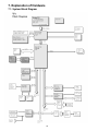
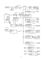
7 Explanation of Hardware ............................................ 56
4.1. Basic Procedures ..................................................... 16
7.1. System Block Diagram ........................................ 56
4.2. Troubleshooting ....................................................... 17
8 Main Unit Extended View ........................................... 58
4.3. Connection Diagram ................................................ 23
8.1. Display section .................................................... 58
4.4. Power-on Self Test (Boot Check) ............................. 24
8.2. Cabinet section ................................................... 59
8.3. Bottom section ................................................... 60
9 Replacement Parts List .............................................. 61
5 Self Diagnosis Test .......................................................... 26
5.1. Outline of Self Diagnostic Test ................................. 26
5.2. Automatic Test .......................................................... 27
5.3. Peripheral Test ......................................................... 28
5.4. Test Selection ........................................................... 29
5.5. Error Messages and Troubleshooting ...................... 30
2
3
4
LASER SAFETY INFORMATION
For U.S.A
Class 1 LASER-Product
This product is certified to comply with DHHS Rules 21 CFR Subchapter J.
This product complies with European Standard EN60825 (or IEC Publication 825)
For all areas
This equipment is classified as a class 1 level LASER product and there is no hazardous LASER radiation.
Caution:
(1) Use of controls or adjustments or performance of procedures other than those specified herein may result
in hazardous radiation exposure.
(2) The drive is designed to be incorporated into a computer-based system or unit which has an enclosing
cover. It should never be used as a stand alone drive.
Danger:
The serviceman should not remove the cover of drive unit and should not service because the drive unit is a
non-serviceable part.
Please check DANGER label on bottom cabinet of the equipment.
. Unplug the AC power cord and remove the battery pack from the equipment before opening the top cover of
the drive.
. When the power switch it on, do not place your eyes close to the top cover to look into the interior of the unit.
LASER Specification
Class 1 level LASER Product
Wave Length:
DVD
650
CD
778
660 nm
787 nm
Laser safety information is appropriate only when drive with laser is installed.
5
Precautions
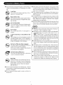
Usage
Handling
Avoid Extreme Heat and Cold
Do not store or use the computer in locations exposed to heat, direct sunlight, or
extreme cold.
Avoid moving the computer between
locations with large temperature difference.
Operation: 5 °C to 35 °C {41 °F to 95 °F}
Storage: -20 °C to 60 °C {- 4 °F to 140 °F}
Avoid Magnetic Fields
Keep the computer away from magnets.
Data stored on the hard disk may be lost.
Avoid Stacking
Do not place heavy objects on top of the
computer.
Do Not Disassemble the Computer
Do not disassemble the computer using
methods other than those shown in this
manual.
This computer contains high-voltage
parts, contact with which may result in
electrical shock. Modification or incorrect
disassembly may result in fire.
Avoid Direct Sunlight on the LCD Panel
The LCD panel should not be exposed to
direct sunlight or ultraviolet light.
Avoid Humidity, Liquids and Dust
Do not store or use the computer in locations exposed to high humidity, liquids
(including rain) or dust.
Avoid Excessive Force on the Display
Do not apply excessive downwardforce
on the display.
Prevent Shock
Avoid subjecting the computer to severe
vibrations or impact. Do not place the
computer inside a car trunk.
Avoid Radio Frequency Interference
Do not place the computer near a television or radio receiver.
Cables
Use of an interface cable longer than 3m(9.84feet)
is not recommended.
Avoiding Low-temperature Burns
Avoid more than casual contact with any
heat producing area of the notebook
computer, AC adaptor, and any option or
accessory you use with it. Even low heat,
if warmer than body temperature, can
cause a burn, if the skin is exposed to the
heat source for a long period of time.
6
7
8
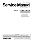
Handling
A
B
This computer has been designed so as to minimize shock to the LCD and hard disk drive, etc.,
but no warranty is provided against such trouble. Therefore, as a precision instrument, be
extremely careful in the handling.
Do not carry the computer while the display is open, or carry it by gripping the display or the
cabinet around the display (see figure A). When closing the display, ensure that the latch is
positioned correctly in the slot .
Do not carry your computer when the power is on.
Do not drop or hit your computer against solid objects.
Remove all external devices, cables, PC Cards sticking out of the computer (see figure B),
SD memory cards, and MultiMedia Cards before transporting the computer.
We recommend preparing a fully charged battery pack.
When transporting a spare battery pack inside a package, briefcase, etc., it is recommended
that it be placed in a plastic bag so that its contacts are protected.
Always carry your computer with you. Never check it in with luggage. For use of the computer inside an aircraft, we recommend asking the airlines regarding their policy on this issue.
It is a good idea to make backup copies on disks and carry them with you.
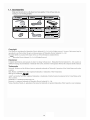
Maintenance
Touch Pad
Display
Avoid using water when cleaning the panel. Ingredients included in water may leave scratches
and reduce readability of the screen.
<When cleaning dust/dirt>
Avoid rubbing off dust/dirt with cloth since it may leave scratch on the screen.
Sweep dust/dirt with fine brush, then wipe it with a dry soft cloth used for cleaning glasses.
<When cleaning oily surface>
Apply camera lens cleaner on a soft gauze and clean it with gentle force. Then, wipe with a
dry soft cloth used for cleaning glasses.
Areas excluding the display
Wipe these areas with a soft cloth, after applying water or detergent diluted with water to the
soft cloth and firmly wringing out excess water.
CAUTION
Do not use benzene, thinner, or rubbing alcohol. Doing so may adversely affect the
surface, e.g., discoloration. In addition, do not use commercially-available household
cleaners and cosmetics, as they may contain components harmful to the surface.
Do not directly add or spray water or detergent. If liquid enters the inside of the
computer, it may cause it to work improperly or be damaged.
9
2006
10
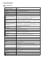
2. Specifications
Main Specifications
Secondary cache memory
Intel® Pentium® M Processor Ultra Low Voltage 753 (1.20 GHz, 2 MB *1 L2 cache, 400
MHz FSB)
Chip Set
Intel® 915 GMS Express chip set
Main Memory
512 MB *1, DDR2 SDRAM (1024 MB *1 Max.)
Video Memory
UMA (128 MB *1 Max.)*2
Hard Disk Drive
60 GB*3
DVD-ROM & CD-R/RW Drive
USB 2.0 connection interface, Buffer underrun error prevention function: Supported
CPU/
٨DVD-RAM
Continuous Data Transfer
Playback
Speed*4*5/
Continuous Data Transfer Speed*4*5/
Recording
Compatible Disk and Compatible Formats*5/Playback
Compatible Disks and Compatible Formats*5/Recording
Display Method
*6
: 2X speed (4.7 GB*3)/1X speed (2.6 GB*3) ٨DVD-R*7: 4X speed (Max.)
4X speed (Max.) ٨DVD-ROM*8: 8X speed (Max.) ٨CD-ROM*8: 24X speed
(Max.) ٨CD-R*8: 24X speed (Max.) ٨CD-RW*8: 24X speed (Max.) ٨+R: 4X speed
(Max.) ٨+R DL: 4X speed (Max.) ٨+RW: 4X speed (Max.)
٨DVD-RW:
write*9: 4X speed, 8X speed, 10-16X speed, 10-24X speed ٨CD-RW write: 4X
speed ٨High-Speed CD-RW write: 4X speed, 8X speed,10X speed ٨Ultra-Speed CDRW write: 10X speed, 10-16X speed, 10-24X speed
٨CD-R
*
٨DVD-ROM (Single Layer, Dual Layer) ٨DVD-Video ٨DVD-R 7(1.4 GB, 3.95 GB, 4.7
GB)*3 ٨DVD-RW (Ver.1.1/1.2 1.4 GB, 4.7 GB, 9.4 GB)*3 ٨DVD-RAM*6 (1.4 GB, 2.8 GB,
2.6 GB, 5.2 GB, 4.7 GB, 9.4 GB)*3 ٨+R (4.7 GB)*3 ٨+R DL (8.5 GB)*3 ٨+RW (4.7 GB)*3
٨CD-Audio ٨CD-ROM
(XA compatible) ٨CD-R ٨Photo CD (multiple session compatible) ٨VideoCD ٨CD-EXTRA ٨CD-RW ٨CD-TEXT
٨CD-R ٨CD-RW
12.1 XGA type (TFT) (1024
× 768 dots)
× 768 dots)*10
Internal LCD Display
65,536/16,777,216 colors (1024
External Display*11
65,536/16,777,216 colors (800 × 600 dots/1024
1024 dots/1600 × 1200 dots/2048 × 1536 dots)
Simultaneous Display on LCD + External Display*11
65,536/16,777,216 colors (800
× 768 dots/1280 × 768 dots/1280 ×
× 600 dots, 1024 × 768 dots)*10
Wireless LAN
Built-in Intel® PRO/Wireless 2915 ABG
LAN*12
IEEE 802.3 10Base-T, IEEE 802.3u 100Base-TX
Modem
Data: 56 kbps (V.92) FAX: 14.4 kbps
Sound
WAVE and MIDI playback, Monaural Speaker (built in)
Card Slots
PC Card Slot × 1: (One Type I or Type II, Allowable current 3.3 V: 400 mA, 5 V: 400 mA)
SD Memory Card Slot*13 × 1
RAM Module Slot
DDR2 SDRAM, 172-pin, 1.8 V, Micro DIMM, PC2-3200 Compliant*14
Interface
USB Ports × 2 ( USB2.0 × 29)*15 / Modem Port ( RJ-11 ) / LAN Port ( RJ-45) *12 /
External Display Port: Mini Dsub 15-pin female / Microphone Jack: Miniature jack, 3.5
DIA / Headphone Jack: Miniature jack, 3.5 DIA / Mini Port Replicator connector : Dedicated 50-pin male
Keyboard/Pointing Device
83 keys/Touch Pad
Power
AC adaptor or Battery pack
AC Adaptor*16
Input: 100 V - 240 V AC, 50 Hz/60 Hz
Output: 16 V DC, 2.5 A
Battery Pack
Li-ion 7.4 V, 7.8 Ah
Operating Time*17
Approx. 4 hours - 7.5 hours *18 (Approx. 5.5 hours*19) (Disable Economy Mode (ECO))
Charging Time*20
Approx. 5 hours (Power off)/Approx. 6.5 hours (Power on)
11
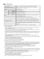
Main Specifications
Power Consumption*21
Approx. 35 W*22 / Approx. 40 W (maximum when recharging in the ON state)
Physical Dimensions (W × H × D)
268 mm × 24.9 mm (at the front)/44.3 mm (at the rear) × 210.4 mm (excluding
protrusion) {10.6 " × 1.0 " / 1.8 " × 8.3 "}
Weight*23
Approx. 1290 g {2.8 lb.}
Operation
Environment
Storage
Temperature
5°C to 35°C {41°F to 95°F}
Humidity
30% to 80% RH (No condensation)
Temperature
-20°C to 60°C {-4°F to 140°F}
Humidity
30% to 90% RH (No condensation)
OS*24
Microsoft® Windows® XP Professional with Service Pack 2 with Advanced Security
Technologies (NTFS File system)
Pre-installed Software*24
Microsoft® Internet Explorer 6 Service Pack 2 / DirectX 9.0 c /
Microsoft® Windows® Media Player 10 / Microsoft® Windows® Movie Maker 2.1 /
Microsoft® .NET Framework 1.1 / Adobe Reader / Intel® PROSet/Wireless Software
<Only for models with wireless LAN> / SD Utility / Icon Enlarger / Loupe Utility / Touch
Pad Utility / DMI Viewer / PC Information Viewer / WinDVD™5 (OEM Version) / B’s
Recorder GOLD8 BASIC / B’s CLiP 6*25 / Hotkey Settings / Optical Disc Drive PowerSaving Utility / Wireless LAN Switch Utility <Only for models with wireless LAN> / Economy Mode (ECO) Setting Utility / Battery Recalibration Utility / Infineon TPM Professional Package* 28
Setup Utility / Hard Disk Data Erase Utility*26 / Hard Disk Backup Utility*26
*1
*2
*3
*4
*5
*6
*7
*8
*9
*10
*11
*12
*13
*14
*15
*16
*17
*18
*19
*20
*21
1 MB = 1,048,576 bytes
A segment of the main memory is allotted automatically depending on the computer ’s operating status. The size of the Video
Memory cannot be set by the user.
1 GB = 1,000,000,000 bytes. Operating system or some application software will report as fewer GB.
Data transfer speeds indicate values measured by Matsushita Electric Industrial Co., Ltd. The data transfer rate of DVD per 1X
speed is 1,350 KB/s. The data transfer rate of CD per 1X speed is 150 KB/s.
Performance of CD-R, CD-RW, DVD-RAM, DVD-R, DVD-RW, +R, +R DL, and +RW cannot be guaranteed depending on writing
status and recording format. Also, some data cannot be played back depending on the disk, settings, and environment being
used.
In the case of DVD-RAM, only non-cartridge disks or removable cartridge disks can be used.
DVD-R is compatible with 4.7 GB (for General) playback. DVD-R (for Authoring) playback is compatible with disks recorded
using Disk-at-Once recording.
If an unbalanced disk (e.g., a disk with which the balance has been displaced from the center) is inserted, the speed may become
slower if there are large vibrations while the disk is rotating.
Depending on the disk, the writing speed may become slower.
A 16,777,216 color display is achieved by using the dithering function.
Display may be impossible using some connected external displays.
Some devices cannot be used depending on the port type.
Operation has been confirmed for Panasonic SD memory cards with up to 2 GB capacity. The transfer rate using the SD memory
card slot on this computer is 8 MB per second (this is a theoretical value, and differs from actual speeds). The transfer rate is 8
MB per second even if you use an SD memory card that supports high-speed transfer rates. Does not guarantee connection/
operation of all SD devices. Does not support MultiMedia card. Do not insert MultiMedia card.
Only a RAM module designed for DDR2 (PC2-3200) can be added (Panasonic : CF-BAV0256U / CF-BAV0512U).
JEDEC standard 214 pin Micro DIMM cannot be used. PC2100 / PC2700 172 pin Micro DIMM cannot be used .
Does not guarantee operation of all USB-compatible peripherals.
<Only for North America>
The AC adaptor is compatible with power sources up to 240 V AC adaptor. This computer is supplied with a 125 V AC compatible AC cord.
Varies depending on the usage conditions, CPU speed, etc. Measured value when the power saving function on the USB2.0 USB
Root Hub is set to on. (At the time of purchase, the power saving function is set to off.)
When Economy Mode (ECO) is enabled, the operating time becomes approximately 20 % shorter than when it is disabled.
Measured using BatteryMark ™ Version 4.0.1 (LCD brightness : Maximum - Minimum).
Measured using MobileMark ™ 2002 (LCD brightness : 60 cd/m2).
Varies depending on the usage conditions, CPU speed, etc.
It may take a long time to charge a fully discharged battery.
Approx. 1.5 W when the battery pack is fully charged (or not being charged) and the computer is off.
12
*22
*23
*24
*25
*26
*28
Rated power consumption.
Average value. May differ depending on models.
Operations of this computer are not guaranteed except for the pre-installed OS.
Preinstalled B’s CLiP does not support CD-R.
The Product Recovery DVD-ROM is required.
For information on TPM, input [c:\util\drivers\tpm\README.pdf] in [start] - [Run] and refer to the installation manual of “Trusted
Platform Module (TPM)”. You need to install Infineon TPM Professional Package to use TPM.
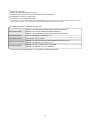
Wireless LAN <Only for models with wireless LAN>
Data Transfer Rates
IEEE802.11a: 54/48/36/24/18/12/9/6 Mbps (automatically switched)*27
IEEE802.11b: 11/5.5/2/1 Mbps (automatically switched)*27
IEEE802.11g: 54/48/36/24/18/12/9/6 Mbps (automatically switched)*27
Standard Supported
IEEE802.11a/IEEE802.11b/IEEE802.11g
Transmission Method
OFDM system, DS-SS system
Wireless Channels Used
IEEE802.11a: Channels 36/40/44/48/52/56/60/64/149/153/157/161/165
IEEE802.11b/ IEEE802.11g: Channels 1 to 11
RF Frequency Band
IEEE802.11a: 5.18 - 5.32 GHz, 5.745 - 5.825 GHz
IEEE802.11b/ IEEE802.11g: 2412 - 2462 MHz
*27
These are speeds specified in IEEE802.11a+b+g standards. Actual speeds may differ.
13
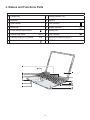
3. Names and Functions Parts
1DPHV
$
)XQFWLRQNH\
,
'LVSOD\LQWHUQDO/&'
%
.H\ERDUG
-
6SHDNHU
&
6WDWHLQGLFDWRU
.
/$1FRQQHFWRU
'
:KHHOSDG
/
0RGHPFRQQHFWRU
(
3RZHUVZLWFK3RZHULQGLFDWRU
0
6HFXULW\ORFN
)
:LUHOHVV/$1VZLWFK
:,5(/(66/$1
0
86%FRQQHFWRU
*
(FRQRP\PRGH(&2LQGLFDWRU
(&2
2
:LUHOHVV/$1DQWHQQDEXLOWLQ
+
%DWWHU\LQGLFDWRU
3
&''9'GULYH
14
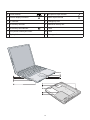
Names
A
Power terminal
H
Microphone input terminal
B
External display connector
I
Audio output terminal
C
PC card slot
J
Emergency hole
D
SD memory card slot
K
Additional memory slot
E
SD memory card indicator
L
Latch
F
Drive power switch/Eject switch
M Latch
G
Display latch
N
15
Battery pack
4 Diagnosis & Repair
4.1. Basic Procedures
16
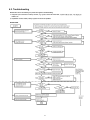
4.2. Troubleshooting
17
When a problem occurs, refer to this page. The “Reference Manual” also contains detailed information. If a problem appears to be
related to a software application, read the software related manual. If you still cannot troubleshoot the problem, contact your
technical support office. You can use the PC Information Viewer to check the computer’s usage status.
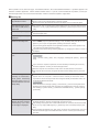
Starting Up
The power indicator or battery indicator is not lit
Check the cable connection for the AC adaptor.
Check to see if a fully charged battery is properly inserted.
Remove the battery pack and disconnect the AC adaptor , then connect them again.
The computer does not operate when a USB device is
connected
The computer may not operate when certain USB devices are connected. Disconnect the
USB device, or set [ Legacy USB Support] to [ Disable] in [ Advanced] menu of the Setup
Utility .
[Enter Password] is displayed
Input your Supervisor Password or User Password. If you have forgotten it, contact your
technical support office.
POST Star tup Error (s) is
displayed
Windows startup, or an operation is extremely slow
Press
F9
in the Setup Utility. This will restore the Setup Utility’s settings to their
default values (except the password settings). Then, the Setup Utility must be run once
again for you to input the appropriate operating environment settings.
(The processing speed depends on the application software used, so this operation may
not cause the processing speed to increase. )
If operations slow down during streaming playback, try changing the number of colors of
the display .
The date and time are incorr ect
You can set the date and time using the following menu:
Windows XP
[start] - [Control Panel] - [Date, Time, Language, and Regional Options] - [Date and
Ti me]
If you continue to experience problems, the internal battery maintaining the clock may
need to be replaced. Contact your technical support office.
When the computer is connected to a LAN, confirm the date and time of the server .
This computer will not correctly recognize the date and time starting from the year 2100
A.D.
When r esuming fr om the
standby or hibernation
mode, [Enter Password]
does not appear even if a
password has been set in the
Setup Utility
Even when a password has been set in the Setup Utility , [ Enter Password ] does not
appear when t he computer resumes from the standby or hibernation mode.
If you want to use the security function when using the standby or hibernation mode, use
the Windows password as follows:
Windows XP
Select the account to change in [start] - [ Control Panel ] - [ User Accounts] and set the
password, then add the check mark for [Prompt for password when computer resumes
from standby] in [ Control Panel ] - [ Performance and Maintenance ] - [ Power Options] [ Advanced ].
When “Invalid system disk.
Replace the disk, and then
pr ess any key.” (or a similar message) is displayed
This means a floppy disk that does not contain system startup information has been left in
the floppy disk drive. Remove the floppy disk, and press any key .
This message may appear when certain USB devices are connected. Remove the USB
device, or set [ Legacy USB Support ] in [ Advanced ] menu of the Setup Utility to [ Disable ].
If the message still appears even after trying the above two measures, this may be an
indication that some type of hard disk failure has occurred. Contact your technical support office.
18
18
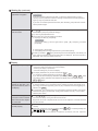
Starting Up (continued)
W hen the administrator
password is forgotten
Set the password again in the following procedure.
Windows XP
If you have created a password reset disk, a message is displayed when you fail to
correctly enter the password. Follow the message’ s instructions and set the password
again by using the password reset disk.
If you have not created a password reset disk, after reinstalling, setup Windows and then
set the password again.
When the pr evious item is
not the cause
Press F9 in the Setup Utility. This will restore the Setup Utility’s settings to their
default values (except the password settings).
Try removing all peripheral devices.
Check a disk error using the following procedure.
1 Display [Local Disk (C:) Properties].
Windows XP
Select [Local Disk(C:)] with the right button in [start] - [My Computer], and select
[Properties] .
2 Select [Tools] - [Check Now].
3 Select [Start] after selecting required items in [Check disk options].
At startup, hold down F8 when [Panasonic] boot screen disappears, and release your
finger when the Windows Advanced Option Menu is displayed. Start the computer in
Safe Mode, and confirm the details of the error.
Display
No display after powering on
When there is no display to an external display ,
• Check your cable connection to the external display .
• Confirm your display is powered on.
• Check the settings for your external display .
The display destination may be set to the external display .
Try changing the display destination by pressing
Fn + F3 .
If you want to switch the display destination repeatedly by pressing Fn + F3 , make
sure that the display destination has switched completely each time before pressing
Fn + F3 again.
The power has not been
turned off, but after a certain period of time, there is
no display
Has the computer been set to the power-saving mode?
To resume operation of your computer from the condition the power of the display is off
(for energy conservation purposes), press any key unrelated to the direct triggering of a
selection, like Ctrl .
To save power, your computer may have automatically entered the standby mode (power
indicator blinks green) or hibernation mode (power indicator turns off). In such cases,
slide the power switch.
W hen the battery pack is
used, the screen is darker
than when the AC adaptor
Press Fn + F2 and adjust the brightness. Note, however, that when the brightness is
increased, the battery running time will become shorter .
Brightness can be set to separate levels for when the AC adaptor is connected and when
is connected
it is disconnected.
The cursor cannot be controlled properly
If you are using an external mouse, ensure that the external mouse has been connected
correctly .
Restart the computer by using the keyboard (Press
, U , and select [Restart] with
, then press Enter ).
If the computer does not respond to keyboard commands, read “No response”.
19
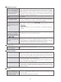
Display (continued)
An afterimage appears (e.g.,
green, r ed, and blue dots
remain on the display) or
there ar e dots not displaying the correct colors
If an image is displayed for a prolonged period of time, an afterimage may appear . This
is not a malfunction. The afterimage will disappear when a different screen is displayed.
High-precision and advanced technologies are necessary in the production of color liquid
crystal displays (color LCDs). Therefore, if 0.002% or less of the picture elements either
fail to light or remain constantly lit (that is, more than 99.998% of elements are functioning properly), no defect is considered to exist.
The screen becomes disordered
Changing the number of colors or resolution of the display may affect the screen. Restart
the computer.
The external display no
longer displays properly
When an external display not compatible with the power saving mode is used with the
computer, the display may not function correctly when the computer enters the power
saving mode. In such cases, turn off the power to the external display .
During simultaneous display,the screen of the external display becomes disordered
Try changing the display by pressing
Fn + F3 .
If you continue to experience problems, try changing the display destination in the fol lowing menu:
Windows XP
[start] - [ Control Panel ] - [ Other Control Panel Options] - [ Intel (R) Extreme Graphics] [ Devices]
When an M PEG file is being played with Media
Player, the display destination cannot be switched using Fn + F3
The display destination cannot be switched while an MPEG file is playing. Stop playing
the MPEG file before switching the display destination.
Application is not displayed
properly, or characters are
garbled
Is the application a non-Unicode program? When non-Unicode programs are run on
Windows XP, you must select the language appropriate to that program.
Set [ Language for non-Unicode programs] in [ Control Panel ] - [ Date, Ti me, Language,
and Regional Options] - [ Regional and Language Options] - [ Advanced] .
Note that only a user with the administrator authority can change this setting.
Shutting Down
W indows cannot be shut
down or restarted
If a USB device is connected, try removing it.
Battery Indicator
The red indicator lights
The battery level is very low (the charge is less than approx. 9% capacity).
Connect the AC adaptor . You can use the computer when the indicator light is orange. If
you do not have an AC adaptor, save your data and power of f your computer. After
replacing the battery pack with a fully charged one, turn your computer on.
The red indicator blinks
Quickly save your data and power off your computer . Remove the battery pack and disconnect the AC adaptor , then connect them again.
If the problem persists, contact your technical support office. Possible failure in
failure in the battery pack or charging circuit.
The orange indicator blinks
Battery cannot be recharged temporarily because the internal temperature of the battery
pack is outside of the acceptable temperature range for recharging. Once the allowable
range requirement is satisfied, charging begins automatically.Your computer can be used
normally in this state.
Sound
W hen starting Sound Recorder, it displays the message: “Ther e was an error
updating the registry.”
Sound Recorder displays this error message when started by a user with a limited account
if the user’s language setting is different to that of the user with administrator authority
which last started it .
This will not affect the operation of the computer .
20
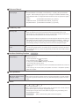
Reference Manual
The Reference Manual is
not displayed
Is Acrobat Reader installed?
If Acrobat Reader is not installed, run the following* 1 in [start] - [Run] to reinstall the
program. When installing the program, do not change the installation destination folder .
If the destination folder is changed, the Reference Manual cannot be opened from [start]* 2
menu.
* 1 English
: [c:\util\reader\m\acroreader51_enu_full.exe]
Traditional Chinese : [c:\util\reader\tc\acroreader51_cht_full.exe]
Simplified Chinese : [c:\util\reader\sc\acroreader51_chs_full.exe]
SD Memory Card
Cannot log on with the SD
memory card
Windows logon user name and password are not set in the SD memory card correctly.
Enter the Windows user name and password without using the SD memory card.
After logging on, reset the SD memory card, or use the [Control Panel] to create a user
with the user name and password set on the SD memory card.
If you change the setting for Language for non-Unicode programs after the check mark has
been added in [Use when logging on to Windows] under [SD Card Settings] - [Setting for
this SD card], remove the check mark from [Use when logging on to Windows] under [SD
Card Settings] - [Setting for this SD card], and set the user name and password again.
Cannot use the SD memory
card
When using the SD memory card with other peripheral devices, format the SD memory
card using the peripheral device. For details, refer to the instruction manual for that device.
Note that the SD memory card is not supported by formats other than the SD memory
card standard.
Fast User Switching Function
Some applications may not
work properly
Windows XP
When switching to a different user with the Fast User Switching function, the following
problems may occur.
• Some applications may not work properly.
• Key combination with Fn may not work.
• It may not be possible to set the settings of the display.
• The wireless LAN cannot be used.
• The B’ s CLiP icon will no longer be shown on the taskbar and a CD-RW disc cannot be
written on.
In this case, log off all users, and try the operation once more. If the problem persists,
restart the computer.
Disk Operations
If the DVD-ROM & CD-R/
RW drive vibrates excessively or is noisy
Is the disc bent or labeled?
Check to see if the disc is inserted correctly, and check that the disc is in good condition.
If the disc is good and inserted correctly , set [DVD Drive Speed] to [Low] in the Setup
Utility.
Others
No response
Press Ctrl + Shift + Esc to open Task Manager and close the software application
which is not responding.
After shutting down by sliding the power switch for more than four seconds, slide the
power switch to power on and open the application again.
If the program no longer works normall, delete the program using the following menu.
Then reinstall the program.
Windows XP
: [start] - [Control Panel] - [Add or Remove Programs]
21
4.2.1. List of Error Codes
The following is a list of the messages that BIOS can display. Most of them occur during POST. Some of them display
information about a hardware device, e.g., the amount of memory installed. Others may indicate a problem with a device,
such as the way it has been configured. Following the list are explanations of the messages and remedies for reported
problems.
If your system displays any of the below error messages other that the ones marked with an asterisk ( * ), write down the
message and contact your technical support office. If your system fails after you make changes in the Setup menus, reset
the computer , enter Setup and install Setup defaults or correct the .error.
0200 Failure Fixed Disk
Fixed disk in not working or not configured properly . Check to see if fixed disk is attached properly . Run Setup.
Find out if the fixed-disk type is correctly identified.
0211 Keyboard error
Keyboard not working.
0212 Keyboard Controller Failed
Keyboard controller failed test. Requires repair of system board.
0213 Keyboard locked - Unlock key switch
Unlock the system to proceed.
0230 System RAM Failed at offset : nnnn
System RAM failed at offset nnnn of in the 64k block at which the error was detected.
0231 Shadow RAM Failed at offset : nnnn
Shadow RAM failed at offset nnnn of the 64k block at which the error was detected.
0232 Extended RAM Failed at offset : nnnn
Extended RAM Failed at address line : nnnn
Extended memory not working or not configured properly at offset or address line nnnn.
0250 System battery is dead - Replace and run SETUP
The CMOS backup battery is dead. Replace the battery and run Setup to reconfigure the system
.
*0251 System CMOS checksum bad - Default configuration used
System CMOS has been corrupted or modified incorrectly , perhaps by an application program that changes data stored in
CMOS. The BIOS installed Default SETUP Values. If you do not want these values, enter Setup and enter your own values.
If the error persists, check the system battery or contact your technical support office.
0260 System timer error
The timer test failed. Requires repair of system board.
0270 Real time clock error
Real-time clock fails BIOS test. Requires repair of system board.
0271 Check date and time settings
Real-time clock is illegal. Run Setup and set the date and clock.
*0280 Previous boot incomplete - Default configuration used
Previous POST did not complete successfully . POST loads default values and of fers to run Setup. If the failure was caused
by incorrect values and they are not corrected, the next boot will likely fail. On systems with control of wait states, improper
Setup settings can also terminate POST and cause this error on the next boot. Run Setup and verify t hat t he wait-state
configuration is correct. This error is cleared the next time the system is booted.
02D0 System cache error - Cache disabled
Contact your technical support office.
Failing Bits : nnnn
The hex number nnnn is a map of the bits at the RAM address which failed the memory test. Each 1 (one) in the map indicates
a failed bit. See error 230,231 or 232 for offset address of the failure in System, Extended or Shadow meory.
.
Operating System not found
Operating system cannot be located on either drive A: or drive C:. Enter Setup and see if fixed disk and drive A: are properly
identified.
Press <F1> to resume, <F2> to Setup
Displayed after any recoverable error message. Press <F1> to start the boot process or <F2> to enter a Setup and change the
settings. Write down and follow the information shown on the screen.
22
22
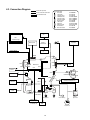
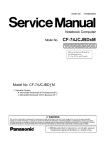
4.3. Connection Diagram
Connection by Cable
Connection Cable
1
Drive FFC
2
LCD Cable
3
Speaker Cable
4
SW Board FFC
5
Antenna PCB-L
6
Antenna PCB-R
7
Modem Cable
8
LAN Cable
9
PAD FFC
10 HDD FPC Unit
11 DC-IN Cable
12 Main-Sub Cable
Direct connection Connectors
Parts on Bottom Side
DFJK9000ZA
DFJS957ZA
DFJS962ZA
DFJK20T108BB
N1ZYYY000002
N1ZYYY000001
DFJS959ZB
DFJS979ZA
DFJK12U112BB
DL3UP1443AAA
DFJS961ZB
DFJS960ZA
Antenna Board
(R)
2
LCD
6
LCD Back Light
3
Wireless
LAN Module
Battery Pack
Keyboard
Speaker
5
Antenna Board
(L)
Inverter Board
CN601
CN26
VGA
CN10
CN15
Main Board
CN11
CN12
HDD
10
CN4
CN600
CN2
11
CN19
DC-IN
MODEM
7
12
CN18
CN23
CN902 USB
CN901
USB Board
CN903 USB
CN25
CN13
1
SD Card
CD-RW,DVD-ROM Drive
CN14
CN16
CN3
CN21
PCMCIA
SLOT
SW6
POWER SW
JK2
JK1
Headphone
Mic
4
SW Board
CN951
SW 7
W-LAN ON/OFF
Lithium Battery
9
DIMM memory
(Option)
CF-BAV0256U
CF-BAV0512U
8
LAN
Touch Pad
23
SW951
Open SW
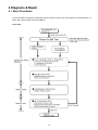
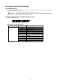
4.4. Power-on Self Test (Boot Check)
4.4.1. Outline of POST
The set has a boot check function called POST (Power-On Self Test) in it. The condition of the main body is disgnosed
by checking beep sound or error code.
Start ……………. Test begins automatically when power switch is set to ON.
Nomal finish …… After memory checking, a beep sound is issued once and the set is placed into automatic stop.
Note: If error occurs, nothing is displayed. (No display of OK, etc.)
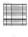
4.4.2. Error Diagnosis by Checking Beep Signal Sound
The beep sound is as follows:
(2-1-2)
(Length of bar shows length of sound)
Table of errors classified by beep sounds
Diagnosis
Main board
Beep signal sound
1-2-2
1-2-3
1-3-3
1-3-4
1-4-4
1-3-1
1-2-4
1-1-3
1-2-1
1-4-1
1-4-2
4-1-4
4-2-1
Error message
DMA Controller error
DMA Controller error
DMA Slave error
DMA Master error
Keyboard Controller error
Memory error
Refresh error
CMOS error
Timer error
Interrupt Controller (Master) error
Interrupt Controller (Slave) error
PCI error
PCI error
(Note) A beep sound is also issued in case of other I/O trouble.
24
4.4.3. Diagnosis by Error Code
Error code
Message
0200
Failure Fixed Disk
0211
Keyboard error
0212
Keyboard Controller Failed
0230
System RAM Failure
at offset : nnnn
0231
Shadow RAM Failure
at offset : nnnn
0232
Extended RAM Failure
at offset : nnnn
No battery on the system
0250
0251
System CMOS checksum
bad
-Default configuration used
0260
0270
0271
System timer error
Real time clock error
Check date and time
settings
Previous boot incomplete
-Default configuration used
0280
02D0
02F5
System cache error
-Cache disabled
DMA Test Failed
Error Description
Fixed disk in not working or not configured properly.
Run the Setup Utility and check that the hard disk
capacity is displayed at [Primary Master]
.
If the [None] is displayed, disk error is occurred.
Keyboard not working. Confirm the keyboard is connected
to the computer and that a key is not being held down.
Keyboard controller failed test.
May require replacing keyboard controller.
System RAM failure at offset nnnn of the 64k block at
which the error was detected. If you installed RAM module,
remove the RAM module and reinstall it.
Shadow RAM failure at offset nnnn of the 64k block at
which the error was detected. If you installed RAM module,
remove the RAM module and reinstall it.
Extended memory not working or not configured properly
at offset nnnn.
CMOS backup battery exhausted.
Battery replacement is required.
System CMOS has been corrupted or modified incorrectly,
perhaps by an application program that changes data
stored in CMOS.
The BIOS installed Default SETUP Values. If you do not
want these values, enter Setup and enter your own values.
If the error persists, check the system battery or contact
Panasonic.
The timer test failed. Requires repair of system board.
Real-time clock fails BIOS test. May require board repair.
Incorrect date and time on the system.
Set the correct date and time using the setup utility.
Previous POST did not complete successfully.
POST loads default values and offers to run Setup.
If the failure was caused by incorrect values and not
corrected, the next boot will likely fail.
CPU trouble.
Server BIOS2 test error: Cannot write to extended DMA
25
Possible faulty part
HDD
Main board
Keyboard
Main board
Main board
Main board
Main board
Extension memory
Lithium battery
Incorrect Setup
Lithium battery
Main board
Main board
Incorrect Setup
Boot-up failure
Main board
Main board
5 Self Diagnosis Test
1. Floppy disk is included for the self-diagnostic tests that should be performed before using this product.
2. Connect External Floppy Disk Drive (FDD) to USB port for diagnosis test.
Important notice
System password
This product has a password function. If this function is turned on, the self-diagnostics tests will not work.
You will need ask the user for the password before performing the self-diagnostics.
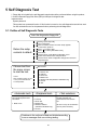
5.1. Outline of Self Diagnostic Tests
Insert the diagnostics floppy disk
Return the setup
contents to default
Choose test from
the menu screen
to start the test.
Caution:
After completing repairs, be sure
to carry out the Automatic test
and Peripheraltest.
<Automatic test>
Tests selected (O) from the test
item list will be performed in
succession.
1. DIAG on FD
Starting up the setup utility
Turn on the power.
When "Panasonic Press F2 to enter setup" appears
on the screen, press F2.
Press " " to select [ Exit ]
Press " " to select [ Get default value ]
Press Enter.
Choose Yes for "Load default Configuration now?"
Select "Save Values & Exit" and press Enter.
Choose Yes for "Save Configuration changes and exit now?"
and press Enter.
Menu Screen
1. DIAG on FD
2. LAN test
3. SD I/F test
4. Modem test
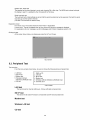
5. Wireless LAN test (Wireless LAN Model only)
6. CD test
Q. Quit
<Peripheral test>
The parallel devices can be tested.
2. LAN test
3. SD I/F test
4. Modem test
5. Wireless LAN test
(Wireless LAN Model only)
6. CD test
<Test selection>
Specifc tests required can
be freely selected and
performed from the test item
list.
Be sure to carry out the Selection
test only when necessary.
Problems in the unit are located and divided according
to error messages that occur during testing.
26
5.1.1. List of main test items
The selection item displays the items selected under Automatic test. If you select Automatic test, these test items
will be performed automatically. You can use Selection test to choose items from the menu screen that you want
to have tested.
These items are shown below.
Test classification
1
2
3
4
5
6
7
8
9
10
11
12
13
14
15
16
17
18
19
20
21
22
23
24
25
26
27
28
29
30
31
CPU
(CPU related)
RAM (Memory related)
CONTROL
(Control ICs on the main
board, etc.)
IO
(Input-output)
COMMUNICATION
AUX
(Auxiliary functions)
VIDEO
(Display related)
DISK
(FDD, HDD)
UNIQUE
(Individual functions)
Test function settings
Test items shown on the screen
SPEAKER TEST
VESA MODE TEST
A20 GATE TEST
CACHE ON/OFF TEST
NPU OPERAND TEST
RAM STANDARD TEST
DMA PAGE REG TEST
DMA REGISTER TEST
DMAC TRANSFER TEST
PIC HALT INSTRUCTION TEST
PIC REGISTER TEST
RTC CMOS RAM TEST
RTC TEST
PIT CH0 TEST
PIT CH1 TEST
PIT CH2 TEST
KEYBOARD REG TEST
PS/2 MOUSE REG
SERIAL WRAP TEST
SERIAL ALL INTERNAL TEST
PARALLEL REGISTER R/W
PCIC ALL TEST
Card Bus Reg
USB Reg
VGA ALL TEST
SVGA RAM TEST
FD WT/RD/WP TEST
HDD ALL TEST
ECP REGISTER R/W
EPP REGISTER R/W
EXT. CMOS R/W TEST
Contents
Speaker test
VESA mode test
Address A20 line
Cache memory on/off test
Floating point processor function test
Memory standard test
DMA page register test
DAM register test
DAM transfer test
Interrupt controller halt instruction test
Interrupt controller register test
Real time clock CMOS test
Real time clock test
interrupt timer CH0
interrupt timer CH1
interrupt timer CH2
Keyboard test
Mouse registration test
Serial loop back (jig required)
Serial port interior test
Parallel register R/W test
PCIC test
Card Bus register test
USB register test
VGA test
SVGA RAM test
FD WT, RD WP test
Only HDD lead test selected
ECP register R/W test
EPP register R/W test
Extension CMOS R/W test
Test condition save/play
Test automatic execute
Error display (Paging style)
Following file command
Test executed on run settings by selecting command
Select displayed items Error, Log, Option
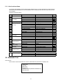
5.2. Automatic Test
Test execution
From the menu screen shown below For Celeron models Select and press Enter for DIAG on FD
1. DIAG on FD
2. LAN test
3. SD I/F test
4. Modem test
5. Wireless LAN test (Wireless LAN Model only)
6. CD testQ. Quit
menu screen
27
Select
28
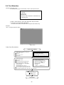
5.4. Test Selection
Starting up the input menu
1. From the menu screen shown below, choose Quit and press Enter.
1. DIAG on FD
2. LAN test
3. SD I/F test
4. Modem test
5. Wireless LAN test (Wireless LAN Model only)
6. CD testQ. Quit
menu screen
2. When A: \DIAG appears, input "JDG_W4H, EXE" and press Enter.
3. The input screen shown below will appear.
To choose menu items, hold down "ALT" and press the selection key.
Example:
"ALT" + F brings up the File menu.
Input screen
Order of test flow selection
Input screen startup
1. Reading the test conditions settings file
Press "ALT" and "F".
2 Press "L".
3 Press "ALT" and "O".
4 Press Enter.
If the test condition settings
file is not read, this means
the test program is not running correctly
.
2. setting the test items
[ Saving selected test items ]
Press "ALT" and "S".
2 Press "S".
If you change the file name when
3 Choose the test item and press Enter.
saving the file in step 6 , you can
4 Choose the test whose settings arecreate test condition settings for
custom test items.
to be changed, press "A" for AdditionalExample:
and "R" for Erase.
CF-W4. * * *
TEST1. * * *
All initial VAlues are "0" so set
tests other than the necessary ones to "1".
5 Press "O" twice to return the menu screen.
6 To save the selected list, press "ALT" and "F" at the file menu.
Starting the test
Press "ALT" and "R".
Press "R".
This will start the test.
End of test
29
5.5. Error Messages and Troubleshooting
The table below explains the parts that may be faulty or damaged should an error message occur while performing the various test
items of the self diagnostics program.
Test classification
1 CPU
2 (CPU related)
3
RAM
4
(Memory related)
5 CONTROL
6 (Control ICs on the
7 main board, etc.)
Screen display test items
A20 GATE TEST
CACHE ON/OFF TEST
NPU OPERAND TEST
RAM STANDARD
DMA PAGE REG TEST
DMA REGISTER TEST
DMAC Transfer TEST
PIC HALT INSTRUCTION
8
TEST
PIC REGISTER TEST
9
RTC CMOS RAM TEST
10
RTC 12/24 HOUR TEST
11
SPEAKER TEST
12
PIT CH0 TEST
13
PIT CH1 TEST
14
PIT CH2 TEST
15
KEYBOARD REG. TEST
16 IO
PS/2 MOUSE REG.
17 (Input-output)
18 COMMUNICATION SERIAL WRAP TEST
SERIAL ALL INTERNAL TEST
19
PARALLEL REGISTER R/W
20
PCIC ALL TEST
AUX
21 (Auxiliary functions) Card Bus REG
USB REG
VGA ALL TEST
22 VIDEO
SVGA RAM TEST
23 (Display related)
VESA MODE TEST
24
FD WT/RD/WP TEST
25 DISK
HDD ALL TEST
26 (FDD/HDD)
ECP REGISTER R/W
27 UNIQUE
EPP REGISTER R/W
28 (Individual
EXT. CMOS R/W TEST
29 functions)
Contents
Possible damaged or faulty part
Address 20 line
Main board
Cache memory on/off
Floating point processor function
Memory standard
Main board
DMA page register
DAM register
DAM transfer test
Interrupt controller
Interrupt controller
Real time clock CMOS
Real time clock test
Speaker
Interrupt timer CH0
Interrupt timer CH1
Interrupt timer CH2
Keyboard
Mouse
Serial loop back (jig required)
Serial port
Parallel register
PCIC
Card Bus port
USB port
VGA
SVGA RAM
VESA mode
FD write/read/write protection
Only HDD lead selected
Parallel port
Parallel port
Extension CMOS R/W test
30
Main board
Main board
Main board
Main board
Main board
Main board
Main board
LCD, main board, cable
Main board
LCD, main board, cable, connector
FD, main board, cable
HDD, main board, cable, connector
Main board, cable, connector
Main board, cable, connector
Main board
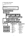
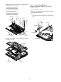
6 Disassembly instructions
6.1.
Disassembly Flow Chart
Main Unit
6.2.1.
Preparation
1. End the Windows.
2. Turn off the Power, and then remove the AC Adaptor or Battery Pack.
3. Remove any optional DIMM Memory Cards or PCMCIA Cards.
4. Remove any other peripherals or Connected Devices.
6.2.2.
6.2.3.
HDD
Keyboard
6.2.4.
Top Case
6.2.5.
6.2.7.
SW Board
6.2.9.
Speaker
Touch Pad
6.2.6.
6.2.8.
Disk Cover
Main Board
6.2.14.
Antenna Board
(L, R) / DC-IN
6.2.13.
USB Board
Drive Unit
6.2.15.
6.2.16.
W-LAN Module
Solenoid
LCD Knob
6.2.12.
6.2.11.
6.2.10.
MODEM
6.2.17.
Card Bus ejector
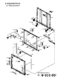
Main replaceable parts
6.2.1.
Display Unit
6.2.18.
LCD Unit
6.2.2.
6.2.3.
6.2.19.
Hinge Cover
6.2.4.
6.2.5.
LCD Unit / LCD Rear
6.2.6.
6.2.7.
6.2.20.
6.2.21.
Inverter Board
6.2.8.
6.2.9.
Battery Pack
DIMM Cover
Side Cover
Keyboard
HDD
HDD FFC
HDD Cover
Top Case
SW Board
Disk Cover Open Knob
Disk Cover
Touch Pad
Touch Pad Knob
Touch Pad Ring
PAD FFC
LCD Knob
Speaker
31
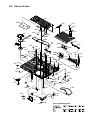
6.2.10.
6.2.11.
6.2.12.
6.2.13.
6.2.14.
6.2.15.
6.2.16.
6.2.17.
6.2.18.
6.2.19.
6.2.20.
6.2.21.
Solenoid
Main Board
Drive Unit
USB Board
Antenna Board
Antenna Cover(L, R)
W - LAN Module
Heat Spreader
MODEM
Card Bus ejector
LCD Unit
Hinge Cover
Hinge (L, R)
LCD Unit
LCD Rear
LCD Front
Inverter Board
LCD Cable
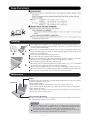
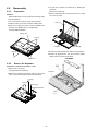
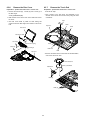
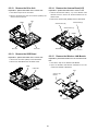
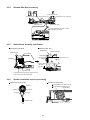
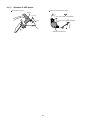
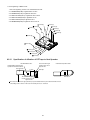
6.2.
3. The LCD unit is opened up to about 90° by operating the
LCD Knob.
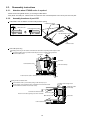
Disassembly
6.2.1.
Preparation
Remove the 6 Hooks (B).
4. Open the Keyboard from LCD side and then turn it inside
out on the Top Case.
Attention:
Before disassembly, be sure to perform the following steps.
1. End the Windows.
2. Turn off the power and then remove the AC Adaptor.
3. Slide the Hooks (A) and then remove the Battery Pack.
LCD unit
Hook (B)
4. Remove the Screw (A) and then remove the DIMM cover.
(Remove if the DIMM memory is equipped with)
Screw(A):XSB2+4FNL(N17)
Battery Pack
Hook (A)
Hook (B)
LCD Knob
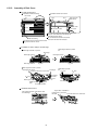
5. Remove the Heat Spreader from buttom of the Keyboard.
Screw (A)
6. Remove the Keyboard FFC from the Connector (CN15),
(CN26) and then remove the Keyboard.
DIMM cover
6.2.2.
Heat Spreader
Remove the Keyboard
CN26
Preparation : perform the section 6.2.1. first.
1. Remove the 4 Screws (F).
Screw(F):DXQT2+E12FNL(N11)
Keyboard
2. Remove the Keyboard Hook Plate and then remove the
Hook of back side of Keyboard with small screwdriver.
Screw (F)
Screw (F)
Screw (F)
Keyboard Hook Plate
CN15
32
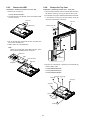
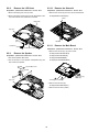
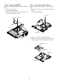
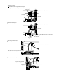
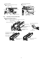
6.2.3.
Remove the HDD
6.2.4.
Preparation : perform the section 6.2.1. 6.2.2. first.
Remove the Top Case
Preparation : perform the section 6.2.1. , 6.2.2. first.
1. Remove the 2 Screws (V).
1. Insert a small screwdriver into the hole and slide the look in
the direction shown by arrow (C) to open the Disc Cover.
Screw(V):DFHE5025XA(N1)
2. The Anttena Cover (R) is rotated from the Bottom Case side
in the direction of arrow (A) and the Antenna Cover (R)
removed in the direction of arrow (B).
2. The slide is done in the direction of the arrow and the HDD
Cover is removed.
Screw (V)
LCD unit
Antenna cover (R)
HDD Cover
B
A
3. Lift up the HDD Unit and remove the FFC Connector and
then remove the HDD Unit.
C
4. HDD is taken out of the HDD Case.
Note:
Please do not bend pins of the HDD Connector, at the
time of removing HDD and FFC Connector.
Back Side
HDD Case
HDD
Hole
FFC Connector
HDD Unit
Small
screwdriver
HDD FFC
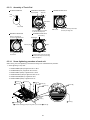
3. Remove the 3 Screws (B), 2 Screws (C) and 3 Screws (E)
from the Bottom Case.
Screw(B):DRHM0092ZA(N4)
Screw(C):DXHM0057ZA(N7)
Screw(E):DXHM0039ZA(N6)
Screw (B) Screw (E)
Screw (B)
Screw (E)
Screw (E)
Screw (B)
Screw (C)
Screw (C)
33
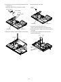
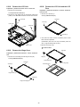
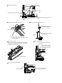
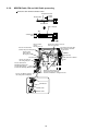
4. Remove the 3 Screws (I), 2 Screws (J), 2 Screws (K) and 2
Screws (L) from the Top Case.
6.2.5.
Preparation : perform the section 6.2.1. to 6.2.4. first.
Screw(I):DXQT2+E6FNL(N13)
1. Peel off the Tape.
Screw(J):DXQT26+D8FCL(N16)
2. Remove the Solenoid Cable.
Screw(K):DXQT2+E6FCL(N12)
3. Remove the 1 Screw (Q) and then remove the SW Board.
Screw(L):DFHE5025XA(N1)
Screw(Q):DXHM0057ZA (N7)
Screw(R):DXQT2+E12FNL(N11)
Note:
Screw(S):DXQT2+E6FNL(N13)
Screw (J)
Remove the SW Board
Note it that the Disc Eject Knob comes off at the same
time.
Disc Cover
Screw (K) Screw (K)
Screw (I)
Screw
(J)
Tape
Screw
(I)
Screw (Q)
Switch Board
Screw (L)
Screw (R)
Disc Eject Knob
Screw (L)
Screw (I)
Screw (S)
5. Lift up the Top Case, remove the Pad FFC and then
remove the Top Case.
Solenoid Cable
Top Case
FFC (PAD)
FFC (SW)
34
Top Case
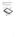
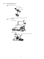
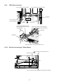
6.2.6.
Remove the Disc Cover
6.2.7.
Preparation : perform the section 6.2.1. to 6.2.4. first.
Remove the Touch Pad
Preparation : perform the section 6.2.1. to 6.2.4. first.
1. Remove the 2 Screw (R), 1 Screw (S) and 1 Screw (T) of
the Disk Angle.
1. Peel off the Tape.
2. The 6 Hooks of the Pad Cover are depressed in the
direction of the center of the Touch Pad by using the small
screwdriver.
Screw(T):DXHM0057(N7)
2. Slide the Disc Cover to the Disc Cover Shaft and remove
the Cover.
Tape
3. The Disk Cover Shaft is pulled out while sliding and
removed it from the Disk Angle in the direction of the Touch
Pad.
Hook
Top Case
Hook
Disc Cover
Disk Cover Shaft
Screw (R)
Disc Cover Spring
Hook
Screw (T)
Disk Angle
PAD FFC
Hook
Top Case
3. Remove the Hooks of the Toutch Pad and the Pad Button,
and remove the Touch Pad.
Pad Cover
Touch Pad
Pad bottun
Hook (F)
Hook (F)
35
6.2.8.
Remove the LCD Knob
6.2.10.
Preparation : perform the section 6.2.1. to 6.2.4. first.
Remove the Solenoid
Preparation : perform the section 6.2.1. to 6.2.4. first.
1. Remove the Spring from the Top Case.
1. Remove the 1 Screw (Z) and then remove the Solenoid.
2. Remove the Hook of LCD Knob from the Stopper Rib of the
Top Case and then the LCD Knob is removed.
Screw(Z):DXQT2+F2FNL(N14)
Screw
Stopper Rib
Top Case
Latch
Spring
Solenoid
6.2.11.
LCD Knob
Location of the Spring
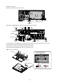
Remove the Main Board
Preparation : perform the section 6.2.1. to 6.2.4. first.
1. Remove the 1 Screw (D), (H) and 2 screws.
6.2.9.
Screw(D):DXQT2+E10FNL(N10)
Remove the Speaker
Screw(H):DXQT2+D4FNL(N9)
Preparation : perform the section 6.2.1. to 6.2.4. first.
Screw(G):DFHE5035ZB(N2)
1. Peel off the Speaker Box Sheet.
Screw(W):K1YE50000022(N500)
2. Peel off the tape on the Speaker and Speaker Ring and
then remove the Speaker.
Speaker Box Sheet
Speaker
Screw (G)
Screw (W)
Speaker
Ring
Screw (D)
Top Case
Screw (H)
2. Remove the 2 Screws (N).
Screw(N):DXQT2+E6FNL(N13)
3. Remove the Connector (CN23)
36
4. The Antenna Cover (L) is inclined in the direction of arrow
A and remove it.
6. Remove the DC-IN Jack Holder.
Remove the Antenna Cover (L) from the Top Case.
DC Jack
Holder
Antenna Cover (L)
A
Antenna PCB (L)
Screw (N)
Screw (N)
Main Board
Bottom Case
7. Returns the Main Board on the reverse.
Peel the Tape of the Drive FFC and remove the FFC.
Main Board
8. Remove the Connector (CN3) and the Connector (CN16) of
LAN Cable.
Bottom Case
CN23
Peel off the Tape of HDD FFC and remove the FFC.
5. Remove the Connectors (CN10) and (CN11) of LCD Cable.
Remove the Main Board.
Tape
LCD Cable
CN10
CN11
LAN
cable
Lithium Battery
Cable
37
CN3
CN16
Tape
6.2.12.
Remove the Drive Unit
6.2.14.
Preparation : perform the section 6.2.1. to 6.2.4. first.
Remove the Antenna Board(L,R)
Preparation : perform the section 6.2.1. to 6.2.11. first.
1. Peel off the Tape from the Connector.
1. Remove the Antenna Cable (L, R) on the Wireless LAN
Module and then remove the Antenna Board from the
Bottom Case.
2. Remove the Drive FFC from the Connector (CN501) and
remove out the Drive Unit.
2. Remove the DC-IN Cable (CN600) from the Main Board.
Tape
CN501
Antenna Cable (R)
Antenna PCB (L)
Antenna Cable (L)
CN600
Drive unit
6.2.13.
Drive FFC
Bottom Case
DC - IN Cable
Remove the USB Board
6.2.15.
Preparation : perform the section 6.2.1. to 6.2.4. first.
Remove the Wireless LAN Module
Preparation : perform the section 6.2.1. to 6.2.4. and 6.2.14.
first.
1. Remove the Connector (CN23) on the Main Board.
2. Remove the USB Board from the Bottom Case.
1. Peel off the Tape on the Wireless LAN Module.
2. Open the Wireless LAN Module maintenance arm and
remove the Wireless LAN Module.
CN23
USB Cable
Tape
Wireless LAN
Module
USB Board
Main Board
38
6.2.16.
Remove the MODEM
6.2.17.
Preparation : perform the section 6.2.1. to 6.2.4. and 6.2.11.
first.
Remove the Card Bus Ejector
Preparation : perform the section 6.2.1. to 6.2.3. and 6.2.11.
first.
1. Remove the 2 Screws (O).
1. Remove the 1 Screw (P) from connected side of Main
Board.
Screw(O):DXQT2+D25FNL(N8)
Screw(P):DFHE5025XA(N1)
2. Remove the MODEM to the vertical direction from
Connector (CN8) on the Main Board.
Screw (P)
Screw (O) Screw (O)
MODEM
CN18
Main Board
2. Return it on the revers to Card Bus Ejector side.
3. Remove the 2 hooks (C) of the Card Bus Ejector from the
Connector (CN14) and the Card Bus Ejector is removed.
Card Bus Ejector
Hook(C)
Main Board
CN14
39
6.2.18.
Remove the LCD Unit
6.2.20.
Preparation : perform the section 6.2.1. to 6.2.4. first.
1. Remove the 2 Screws (M)
Remove the LCD Unit and the LCD
Rear
Preparation : perform the section 6.2.1. to 6.2.4. and 6.2.18.
to 6.2.19. first.
Screw(M):DXQT26+D5FNL(N15)
1. Remove the 2 Screws (Y).
2. Remove the LCD Cable from the Connectors (CN10) and
(CN11) on the Main Board and then remove the LCD Unit.
Screw(Y):DRHM0074ZA(N3)
Screw (M)
LCD Unit
Screw (Y)
LCD Cable
Screw (M)
CN10
CN11
Screw (Y)
2. The LCD Front Case and the combination parts of LCD
Rear Case are separated.
(Combination parts are 6 the top and bottom places for
each, 4 right and left places for each)
3. Remove the Hinge (L, R).
Bottom Case
Hook Position
6.2.19.
Remove the Hinge Cover
LCD Unit
Preparation : perform the section 6.2.1. to 6.2.4. and 6.2.18.
first.
1. Remove the 2 Screws(U) and the Hinge Cover(L,R).
Hinge (L)
Screw(U):DRHM0074ZA(N3)
LCD Front Case
LCD Unit
LCD Rear Case
Screw (U)
Hinge Cover (L)
Screw (U)
Hinge Cover (R)
40
Hinge (R)
6.2.21.
Remove the Inverter Board
Preparation : perform the section 6.2.1. to 6.2.4. and 6.2.18.
to 6.2.20. first.
1. Remove the LCD Cable from the Inverter.
2. Peel off the Tape for fixation from Inverter Case.
3. Remove the Inverter with the Inverter Case.
LCD Front Case
LCD Hook
LCD High voltage
2pin Wire Rod
Inverter Box
Tape
Gasket Cloth
LCD Cable
41
6.3.
Reassembly instructions
6.3.1.
Attention when CF-W4G series is repaired
· Please execute writing BIOS ID when you exchange the Main Board.
· Parts (Sheet and rubber) etc. related various the Conductive Cloth and Heat Spreader cannot be recycled. Use new parts.
6.3.2.
Assembly knowhow of part LCD
LCD Rubber, LCD side Rubber and LCD backing Rubber’s putting
LCD Rubber (Upper)
LCD Rubber (Upper
big
small LCD Front Case
LCD parallel after putting
LCD Side Rubber
LCD Back Rubber (Lower)
LCD Front Case
LCD Cable processing
Clamping processing of LCD Cable, LCD Connector connection and putting of PET Tape of cable
The LCD Insulation Sheet is peeled off and after processes as shown in the figure below,
1 2mm
Put the Insulation Sheet.
PET Tape
1
2mm
LCD Insulation Sheet
Connector
LCD Frame Clamp
A red line of the cable is matched to the LCD Frame externals.
0
1mm
Putting of The Conductive Cloth
The Conductive Cloth is put and after putting, a both side tape is put.
Process the part in the signal line of the LCD Cable in the Conductive Cloth.
Put the Conductive Cloth on the connector surely.
Connector of externals match
There must not be beginning to see from externals.
Connector
Both Side Tape
LCD Insulation Seat
42
Insulation seat of edge match
0 1mm
Conductive Cloth
(LCD Label)
LCD Cable
Putting of PET Sheet
The cable must not run aground on the damper.
Along the LCD Module and put the LCD Cable (Inverter part) with the PET Tape.
PET Tape
Conductive Cloth (LCD cable)
LCD Cable
(Inverter part)
LCD Cable
Damper
Putting of Rear Damper
Conductive Cloth (LCD cable)
LCD Cable
Rib application putting of LCD Front Case
0 1mm
Externals suiting of Inverter Case
0 1mm
Rear Damper
Processing of Inverter Cable
The cable must not come in succession.
Inverter Cable
The cable must not run aground on the cushion.
Putting of Gasket (LCD)
Put on Hinge (R) surely.
The line of the remainder
is put on Hinge (R) side.
Gasket (LCD)
Externals suiting of reflector
0 1mm
Hinge (R)
Put the reflector part surely.
43
Putting of LCD Damper(C)
LCD Damper(C)
Plinth externals match
0 1mm
Rib application putting of LCD Front Case
0 1mm
Rib application putting of LCD Front Case
0 1mm
Rib edge match of LCD Front Case
0 1mm
Putting of Conductive Cloth of LCD Cable
Drawing out specification of LCD Cable
LCD Cable (Inverter)
75
5mm
Conductive Cloth is wrapped
(Leave the half)
The Cable is processed under the shaft .
Note:It is confirmed that the cable does not narrow
between cabinets.
LCD Cable processing 2
LCD cable processing 1
Process the LCD Cable (2) such as DC-IN Jack Holders,
after process the Conductive Cloth of the LCD cable puts
as shown in the figure below.
0
Processing cable to under point
hanging part
Processing the cable to
the DC-IN Jack Holder
The cable is processed
to the ditch
1mm
0
1mm
Put the Conductive Cloth
Connector connection specification
The order of connecting connector
Inverter Cable LCD Cable
DC-IN Jack Holder
44
6.3.3.
Assembly of Brake Lever
Brake Lever completion chart
Brake Spring
Brake Lever
Brake Pad
Do not touch the bonding side when the brake pad is affixed.
Brake Lever built-in figure
Surface chart
In the slide and then install.
Brake lever preparation goods
The above is
shape.
The back chart
Be sure not to do the slide with struck the rib.
45
6.3.4.
Solenoid Wire Rod processing
Inserts between ribs
Up that there is no screw hole
Inserts under the rib
Solenoid Cable
Disk Cover Lock
Solenoid with cable
The Solenoid with the cable is made
on the Disk Cover Lock
6.3.5.
Switch Board assembly specification
Connection to SW Board
SW Board FFC
Affixation of PET Tape
SW Board FFC
Fold as valley type
Terminal Side
Suiting with
shape of board
0 1mm
SW Board
Central suiting
with the pin
0 1mm
Suiting with shape of case
0 1mm
Tape
Pin
Screw
Disk Eject Knob
To confirms that the Lever of the switch has been
surely inserted in the ditch of the knob
6.3.6.
Speaker installation and Line processing
Soldering of Speaker Cable
Affixation of Speaker Ring
Put it according to the shape of the rib.
Note not running aground in the rib.
Speaker Ring
Speaker
Soldering
Red Line
Soldering
Rib
Black Line
Speaker Cable
Rib
46
Speaker installation
Processing of Speaker Cable
Secure 2mm or more for the space in each rib
and the soldering part.
Rib
Rib
Rib outside suiting
0 1mm
Speaker Box
Rib outside suiting
0 1mm
Soldering Part
2mm or more
Inserts in latch
Inserts in the table side.
Rib
2mm or more
Rib
6.3.7.
Inserts in ditch
Inserts in Ditch
Assembly of Antenna Board Part
Line processing of Antenna Cable (L)
Install the Antenna Board in the Bottom Case.
And process remainder of the Antenna Cable as shown in the figure below.
Boss
Process the cable
with the boss between ribs.
Install DC Jack in bottom
Antenna Cable (L)
Place between the bottom base
and install.
Process the cable to the ditch
of the Bottom Case.
Bottom Case
The terminal must become
straight below.
Antenna Cable (L)
The upper side is close with
the under latch is hooked
the Bottom Case
Antenna Cover(L)
DC Jack Holder
The under latch is hooked
the Bottom Case
47
The under latch is hooked
the Bottom Case
6.3.8.
MODEM Cable, Rib and LAN Cable processing
Conductive Cloth affixation of Modem Cable
Wrap Gasket Cloth.
Modem Cable
Gasket Cloth
Tape is wrapped
Tape
Standard size
8mm
Process under
the pin.
Do not get on up.
Process the remainder
between the pin and the pin.
Process at the
right of the pin.
Do not get on up.
Process the cable so as not to
come in succession.
Peel off the both sides tape
flaking off paper and then
fix to the cover.
Touch the pin.
MODEM
Pin
Pin
Touch the pin.
Shut the cap.
PET
Tape
Process the cable to
the cutting lack part.
LAN
Process between the
Main Board and the Pin.
and do LAN Cable up.
(Prevent from floating by Modem Cable.)
Process the Modem Cable to
the cutting lack of the Board.
Install connector in bottom.
PET
Tape
Pin
Draw out RJ cable
straight.
Divide the cable into the center
and paste the tape vertically.
Paste the remainder to an opposite side.
Main Board
LAN Cable
Modem Cable
48
6.3.9.
USB Cable processing
Process between the pin and the pin.
Process between the boss and the HDD.
Boss
Pin
Process between the pin
and the Main Board.
USB Board
USB Cable
PET Tape
HDD FFC
Fix the substrate
with two pins.
Put the cable when there is no space
between the Main Board and the cable
in the Main Board.
・Process the USB cable on the Drive Board.
Do not multiply the stress by the Drive Board.
USB Cable
Drive
Main Board
Open space between the Drive Board and the cable.
6.3.10.
Wire Rod processing of Lithium Battery
Paste to round shape of the Bottom Case.
Draw out the cable straight.
0
2mm
0
Tape
2mm
Boss
Process the Antenna Cable between the Lithium Battery and the Boss.
49
6.3.11.
Affixation of HDD Gasket
DVD Heat Insulation Pack is pasted
Gasket Cloth is pasted
Gasket
0
1mm
It sticks to the bottom of DVD DRIVE
0
It sticks to the side of DVD DRIVE
1mm
DVD Heat Insulation Pack
50
6.3.12.
Assembly of Disk Cover
Assembly of Disk Cover
Installation of PAD Cover Ring
Installation of Disk Cover Shaft
Disc Cover
Pin 2
Arm spring for
Disk Cover
Pin 1
Convex part
Latch
Insert under
the Hook
Disk Cover Shaft
Convex part
PAD Cover Ring
Insert two Convex parts in the hole of Disc Cover.
Hang two latch on Disc Cover.
Insert the Arm Spring for the Disk Cover in the Disk Cover.
Insert pin 1 of the Disk Cover Shaft through the
inside diameter of the Spring.
Pin 2 of the Disk Cover Shaft must be slided,
and insert in the hole of the Disk Cover.
Installation of various dampers on Disk Angle
Disk Angle Sheet A is pasted.
Disk Angle Sheet B/C is pasted.
Disk Angle
Disk Angle Sheet B
Disk Angle Sheet A
0
1mm
Disk Angle Sheet C
0
1mm
0
Disk Angle FPC Cover is pasted.
Disk Angle FPC Cover
Disk Angle
Insert the hook in the corner hole.
0
1mm
a
b
1mm
PET Tape is pasted.
0
1mm
0
1mm
Disk Angle
Cushion
c
0
Disk Angle Cushion
0 1mm
DXQT2+D25FNL
(N8)
Disk Angle Cushion
mm
PET Tape
Installation of Disk Cover
<Figure after installations>
Arrange Disk Cover Shaft at the left of the bend
of the Disk Angle.
Insertion into a slot makes
Insert the hook in the corner hole.
PIN slide.
51
6.3.13.
Assembly of Touch Pad
Insertion of PAD FFC
Installation of Pad Button
Affixation of PAD Sheet
Top Case
Gasket (PAD)
PAD
FFC
Pin insertion
PAD Button
Touch Pad
The Concave part is inserted
in the hole of a Top Case
PAD Seat
Affixes it according to the inside
concave part edge side
Installation of Pad Cover
Affixation of Touch Pad
Pressurizing
Affixes it according to
the convex positioned part
Pad Cover
Hook
Convex part
Hook
Insert two places in the convex part
in the ditch of a Top Case and hang
Hooks four places.
Touch Pad
6.3.14.
Screw tightening procedure of each unit
When serving, the screw tightening is executed according to the undermentioned procedure.
1. Screw tightening of Top Case
1-1. DXQT2+E6FNL(I:N13) is tightened. No.1 to No.3
1-2. DFHE5025XA(L:N1) is tightened. No.4 to No.6
1-3. DXQT2+E6FCL(K:N12) is tightened. No.7, No.8
1-4. DXQT26+D8FCL(J:N16) is tightened. No.9, No.10
1-5. DXQT2+E12FNL(R:N11) is tightened. No.11
1-6. DXQT2+E6FNL(S:N13) is tightened. No.12
Screw (J)
Screw (K)
Screw (I)
Screw (K)
Screw (I)
Screw (J)
A
Screw (L)
Screw (R)
Screw (L)
Screw (L)
Screw (S)
Screw (I)
Conclude coloring part A pressing when you conclude
Screw (K).
52
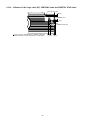
2. Installation of Keyboard
Preparation1. Heat Sheet KB Large is pasted.
0 1mm
0 mm or less of
Inclination
0
1mm
Heat Sheet KB Large
Preparation2. Tape(KBD)/KB FPC Tape/LCD Tape E/KB Edge Sheet ispasted.
0.5
0
0
LCD Tape E
KB FPC Tape
Tape(KBD)
0
3
KB Edge Sheet
0
Tape(KBD)
0
0
0.5
1.The Keyboard is surely installed in the Hook (2 places) at the right and the Hook (4 places) behind a Top Case .
2.The Keyboard is held and the Keyboard Hook is inserted and locked.
Note:Never touch the edge part of the Keyboard Hook by bare-handed.
3.It is confirmed that the Keyboard Hook do not run aground in the rib.
Screw tightening of Keyboard
Keyboard
Hook
Do not run aground on the rib
(Refer to the figure below)
Hook
Hook
Keyboard Hook plate
OK
Keyboard Hook plate
Top Case
Keyboard Hook plate
53
NG
3. Screw tightening of Bottom Case
1.The screw tightening is done in the undermentioned order.
3-1. DXHM0039ZA(E:N6) is tightened.No.1 to No.3
3-2. DXHM0057ZA(C:N7) is tightened. No.4,No.5
3-3. DXQT2+E12FNL(F:N11) is tightened. No.6 to No.9
3-4. DXQT2+E10FNL(D:N10) is tightened. No.10
3-5. DXQT2+D4FNL(H:N9) is tightened. No.11
3-6. DRHM0092ZA(B:N4) is tightened. No.12 to No.14
Screw (E)
Screw (B)
Screw (B)
Screw (F)
Screw (F)
Screw (F)
Screw (E)
Screw (F)
Screw (E)
Screw (B)
Screw (C)
Screw (D)
Screw (H)
Screw (C)
6.3.15.
Specification of affixation of PET tape to Heat Spreader
<The Main Board Side>
The extent that length
remains pastes on an
opposite side.
Heat Radiation Grease(G-751)
Spread with a treatment device.
<The Back Completion Chart>
Heat Spreader
1~2mm
The extent that length
remains pastes on an
opposite side.
PET Tape
PET Tape
1~2mm
Never touch the aluminum edge part directly by bare-handed when the part of aluminum with a thin all
surroundings bends. Correct in that case with a radio pincers etc. and instal.
54
6.3.16.
Affixation of Win Logo Label (XP), CENTRINO Label and ENERTGY STAR Label
Win Logo Label (XP)
2
5mm
CENTRINO Label
2
0
In Win Logo Label / CENTRINO Label / ENERGY STAR Label
Affixation inclination, the both ends difference is within 0.2mm.
55
5
1mm
7mm 2
5mm
ENERGY STAR Label
5mm
7. Explanation of Hardware
7.1. System Block Diagram
56
57
8. Exploded View
8.1. Display Section
K8
N3
K88
K81
N15
K5
K39
K63
K22
N15
K6
K51
K45
K51
K18
K51
K39
E26
K39
K63
K37
K51
K52
K38
K19
K53
K23
K38
E24
K42
K52
K39
K92
K36
K30
K33
K30
K37
N3
K33
K12
K85
N3
K64
K99
K51
E5
K82
Screw tightening torque
N3
8.2. Cabinet Section
E27
K525
K10
K111
K511
K119
K523
K9
K89
K523
K507
K17
K508
E2
K106
E28
K1
K50
N13
PET
Tape
N16
K35
K35
K500
K94
K504
N1
K20
K114
K502
K49
K35
K69
K112
K505
K97
K506
K35
N12
K503
N1
N12
K520 N13
N11
N7
N11
K91
N8
K41
N16
K506
K506
K90
N14
K59
K519
E23
N1
K7
K60
K522
K501
K123
K61
K16
N13
K44
K74
K4
K76
K76
a
E10
K101
K46
K113
E25
K115
a
K116
K117
E3
E13
K93
N7
SW951
N13
Screw tightening torque
8.3. Bottom Section
N8
Screw tightening torque
K105
E22
E29
K100
N8
K96
K108
K102
K509 N13
CN12
CN601
CN13
CN14
E11
SW6
SW7
SW5
K43
JK1
E18
JK2
K98
K107
E9
K24
K104
E14
N500
K49
K510
K34 K110
K109
N5
E4
K32
N1
K79
E19
K527
K524
K526
K86-2
N2
N11
A3
K27
K515
E6
K515
K513
K517
E7
N7
N9
E8
N6
K2
K86-1
K86-3
E12
K512
K86-2
CN902
K3
CN903
K86-1
K86
N4
K86-1
N11
N10
K515
N7 N6
N6
N17
N11
K11
K84
N4
K518
K29
N1
N1
E1
N11
K516
K521
N4
E16
K514
E20
K80
E21
K40
9 Replacement Parts List
Note: Important Safety Notice
Components identified by
mark have special characteristics important for safety.
When replacing any of these components, use only manufacturer's specified parts.
CF-W4HWEZZBM
REF.NO. and AREA
Main Block Unit
CN12
CN13
CN14
CN601
CN902
CN903
JK1
JK2
SW5
SW6
SW7
SW951
E1
E2
E3
E4
E5
E6
E7
E8
E9
E10
E11
E12
E13
E14
E16
E18
E19
E20
E21
E22
E23
E24
E25
E26
E27
E28
E29
Accessories
A1
A2
A3
A4
A500
Packing Material
P1
P2
P3
P5
P6
PART NO.
DESCRIPTION
Q'TY
K1FB315BA003
K1NA09E00076
K1NA68E00096
K1KA10B00233
K1FB104B0055
K1FB104B0055
K2HC103B0205
K2HC103B0205
K0ZZ00000617
ESD165225
K0D112B00071
K0D113B00081
CR-2032/K5A
DFJK12U112BB
DFJK20T108BB
DFJK9000ZA
DFJS957ZA
DFJS979ZA
DFJS959ZB
DFJS960ZA
DFJS961ZB
DFJS962ZA
DL3U11436VBB
DL3U21436VBB
DL3UP1492KAA
N1ZYYY000002
N1ZYYY000001
N5HZC0000014
UJDA769PD1-A
DL3UP1443AAA
N3CAYYY00006
K1YYZZ000060
L0AA01A00018
L5EDD3Q00023
L9AAA5DB0010
N0GB1J000012
N2AZZJ000038
N2EAYYY00006
N5HAZ0000012
VGA CONNECTOR
CONNECTOR
CONNECTOR
CONNECTOR
USB CONNECTOR
USB CONNECTOR
HEADPHONE JACK
MICROPHONE JACK
SLIDE SW
POWER SW
W-LAN SW
SLIDE SW
COIN BATTERY
PAD FFC
SW PCB FFC
DRIVE FFC
LCD CABLE
LAN CABLE
MODEM CABLE
MAIN SUB CABLE
DC-IN CABLE
SP CABLE
PCB, MAIN
PCB, USB
PCB, SW
ANTENNA PCB-L ASSY
ANTENNA PCB-R ASSY
WIRELESS LAN MODULE
CD-R/RW, DVD-ROM DRIVE
FPC, HDD
HDD
CONNECTOR
SPEAKER
LCD
SOLENOID
INVERTER
KEY BOARD US
TOUCH PAD
MODEM
CF-AA1623AM6
K2CG3DR00003
N4HULTA00009
DFQX5574ZA
DFJS954ZA
AC ADAPTOR
AC CABLE
LITHIUM ION BATTERY PACK
MANUAL
MODEM CABLE
1
1
1
1
1
DFPE0806ZB
DFPE0812ZB
DFPE0819ZA
DFPK1037YA
DFPK1194YA
HOLDER
PAD W
BATTERY SPACER
ACCESSORIES BOX
PACKING CASE (EXPORT)
1
1
1
1
1
RTL
RTL
RTL
1
1
1
1
1
1
1
1
1
1
1
1
1
1
1
1
1
1
1
1
1
1
1
1
1
1
1
1
1
1
1
1
1
1
1
1
1
1
1
P7
P8
Mechanical Parts
K1
K2
K3
K4
K5
K6
K7
K8
K9
K10
K11
K12
K16
K17
K18
K19
K20
K22
K23
K24
K27
K29
K30
K32
K33
K34
K35
K36
K37
K38
K39
K40
K41
K42
K43
K44
K45
K46
K49
K50
K51
K52
K53
K59
K60
K61
K63
K64
K69
K74
K76
K79
K80
K81
K82
K84
K85
DFPN0827ZB
DFPN0828ZB
CUSHION T
CUSHION B
2
2
DFBC0314ZB-0
DFBD0180ZB-0
DFBD0182ZA-0
DFBD9006ZA-0
DFBH3043ZA
DFBH3044ZA
DFBS0068ZC-0
DFGB0089VB-0
DFGE0106ZB-0
DFGE0107ZB-0
DFGT1028ZA
DFGX0397ZA-0
DFHE0215ZA
DFHE0416ZA
DFHE0436ZA
DFHE0843ZA
DFHE0844ZA
DFHE0943ZA
DFHE0945ZA
DFHE0953ZA
DFHE0957ZA
DFHG1471YA
DFHG1546ZB-0
DFHG1744ZA
DFHG1766ZA-0
DFHG1767ZA-0
DFHG1768XA-0
DFHG1771ZA
DFHG1772ZA
DFHG1773ZA
DFHG1774ZA
DFHG1808YA
DFHG1778ZA
DFHG1779WA
DFHG1786ZA
DFHG1787ZA
DFHG1797ZA
DFHG1800ZA
DFHP7106YA
DFHP7221YA
DFHP7208YA
DFHP7209ZA
DFHP7210ZA
DFHR3A37ZA
DFHR3A38ZA
DFHR3A71XA
DFHR3A78ZA
DFHR3A95ZA
DFHR3B19ZA
DFHR3B53ZA
DFHR6188ZA
DFKE0772ZA-0
DFKE0773ZA-0
DFKE0774ZA-0
DFKE0775ZA-0
DFKE0815ZA-0
DFKF0255ZB-0
PAD BUTTON
POWER KNOB
LAN SW KNOB
DISK EJECT KNOB ASSY
HINGE-L USA
HINGE-R USA
LCD KNOB
PANASONIC LABEL
PAD COVER
PAD COVER RING
BOTTOM SHEET USA
LCD BATT RUBBER
SHEET
TAPE (KBD)
CLOTH LCD CABLE 1
LCD MAGNET
GASKET PAD
GASKET CLOTH (LCD CABLE)
GASKET CLOTH (LCD)
SHEET
GASKET CLOTH
LCD METAL DAMPER B
LCD RUBBER
M-PCI CUSHION
LCD SIDE RUBBER
DC JACK HOLDER
DISK COVER CUSHION
LCD DAMPER A
LCD DAMPER B
LCD DAMPER C
LCD SIDE DAMPER
HDD CASE ASSY W4 USA
PCMCIA STOPPER CUSHION
LCD HOOK CUSHION
CPU CUSHION
MINI-PCI CUSHION
REAR DAMPER
BATT CUSHION(W4)
BOTH SIDES TAPE
PAD SHEET
LCD FRONT TAPE A
LCD FRONT TAPE B
LCD FRONT TAPE C
SPEAKER RING
SPEAKER BOX
DISK EJECT KNOB SHEET
LCD INSULATOR
INVERTER TAPE
HINGE BACKUP SHEET T4
DISK KNOB SHEET
DISK LOCK BUSH
ANTENNA COVER-L
ANTENNA COVER-R
HINGE COVER L
HINGE COVER R
DIMM COVER LIGHT
LCD FRONT
1
1
1
1
1
1
1
1
1
1
1
1
1
2
1
1
1
1
1
1
1
1
2
1
2
1
4
1
2
2
4
1
1
1
1
1
1
1
2
1
5
2
1
1
1
1
2
1
1
1
2
1
1
1
1
1
1
K86
K86-1
K86-2
K86-3
K88
K89
K90
K91
K92
K93
K94
K96
K97
K98
K99
K100
K101
K102
K104
K105
K106
K107
K108
K109
K110
K111
K112
K113
K114
K115
K116
K117
K119
K123
K500
K501
K502
K503
K504
K505
K506
K507
K508
K509
K510
K511
K512
K513
K514
K515
K516
K517
K518
K519
K520
K521
K522
K523
K524
K525
DFKF8165ZA-0
DFHG371ZA-1
DFKL0026ZA-0
DFMX1174ZA
DFKM0482ZA-0
DFKM0483UA-0
DFKM8170VA-0
DFKE0817ZA
DFMD1189XA
DFMD1190YA
DFMD2165ZA
DFMD3121ZA
DFMD4057ZA
DFMX0635ZB
DFMX1155ZA
DFMX1156ZA
DFMX1158ZA
DFMX1160ZA
DFMX1184ZA
DFMY0399ZA
DFMY3191YA
DFMY3192ZA
DFMY3206ZA
DFMY3207ZA
DFMY3208ZA
DFQT9974ZA
DFQT9948ZA
DFUD0037ZA
DFUN0078ZB
JDBC0044ZA
JDBG0032ZA
JDKJ0059ZA
DFHP7180ZA
DFUD0040ZA
DFHR3C40ZA
DFHR3C14ZA
DFHR3C36ZA
DFHR3C37ZA
DFHR3C38ZA
DFMD7A63ZA
DFHG1833ZA
DFHP7226ZA
DFHR3C39ZA
DFHR3C33ZA
DFHR3B86ZA
DFQT9675ZA
DFKE0781ZA-0
DFHP7228ZA
DFHG1835ZA
DFHR3C13ZA
DFHR3C19ZA
DFHR3C24ZA
DFKE0770ZA-0
DFHG1834ZA
DFHP7231ZA
DFHR3B99ZA
DFHR3C12ZA
DFHR3C18ZA
DFHR3C54ZA
DFMY0421ZA
BOTTOM CASE USA ASSY
FOOT RUBBER
FOOT RUBBER BACK
AUDIO JACK SHEET
LCD REAR (SANKI)
DISK COVER (TOUGH COMBO)
TOP CASE ASSY
DISK ANGLE MG
LCD HOOK
DISK COVER LOCK
DISK CV SHAFT ANGLE
MDC PLATE
KB HOOK F999
SHEET
INVERTER BOX
MAIN PW SHEET1
DVD PWB SHEET
PCMCIA-MAIN SHEET
SW CABLE SHEET
MCH RUBBER
HEAT SPREADER TOP
HEAT SPREADER BOTTOM
MEMORY SHEET TOP
MEMORY SHEET BOTTOM
WLAN SHEET
WINDOWS XP LABEL (FOR NOTE)
CENTRINO LABEL
DISK KNOB SPRING
DISK COVER ARM SPRING
BREAK SPRING
BREAK PAD
BREAK LEVER
LCD TAPE E
LATCH SPRING
DISK COVER SHEET
LCD KNOB SPACER
DISK ANGLE SHEET A
DISK ANGLE SHEET B
DISK ANGLE SHEET C
DISK ANGLE FPC COVER
DISK ANGLE CUSHION
KB FPC TAPE
KB SHEET
LCD CABLE FIX SHEET
DVD HEAT INSULATION PACK
ENERGY STAR LABEL
RJ DUST COVER
RJ DUST COVER FIX TAPE
HDD DAMPER
RJ CABLE SHEET
HDD FPC EDGE SHEET
USB CABLE FIX SHEET
HDD COVER
SP CABLE FIX CUSHION
KBD TAPE
RJ CABLE BLIND SHEET
SP CABLE SHEET
KB EDGE SHEET
HINGE BACKUP SHEET
HEAT SHEET KB LARGE
1
3
2
1
1
1
1
1
1
1
1
1
1
1
1
1
1
1
1
1
1
1
1
1
1
1
1
1
1
1
1
1
1
1
1
2
1
1
1
1
3
1
1
1
1
1
1
1
1
5
1
1
1
1
1
1
1
2
1
1
K526
K527
N1
N2
N3
N4
N5
N6
N7
N8
N9
N10
N11
N12
N13
N14
N15
N16
N17
N500
DFGX0428ZA-0
DFGX0429ZA-0
DFHE5025XA
DFHE5035ZB
DRHM0074ZA
DRHM0092ZA
DRQT2+G6FKL
DXHM0039ZA
DXHM0057ZA
DXQT2+D25FNL
DXQT2+D4FNL
DXQT2+E10FNL
DXQT2+E12FNL
DXQT2+E6FCL
DXQT2+E6FNL
DXQT2+F2FNL
DXQT26+D5FNL
DXQT26+D8FCL
XSB2+4FNL
K1YE50000022
BATTERY SHEET
BATTERY SHEET L
SCREW
SCREW
SCREW
SCREW
SCREW
SCREW
SCREW
SCREW
SCREW
SCREW
SCREW
SCREW
SCREW
SCREW
SCREW
SCREW
SCREW
SCREW, I/O PIN
1
1
6
2
4
3
1
3
4
6
1
1
6
2
6
1
2
2
1
2