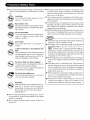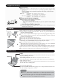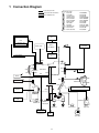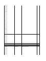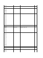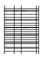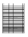
1
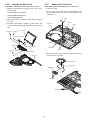
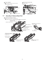
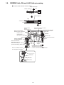
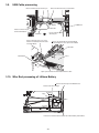
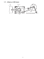
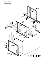
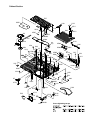
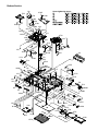
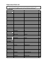
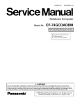
ORDER NO. CPD0511051C1
Personal Computer
CF-W4
This is the Service Manual for
the following areas.
M …for U.S.A. and Canada
Model No. CF-W4GWCZZ 1 2
1: Operation System
B: Microsoft® Windows® XP Professional
2: Area
M: Refer to above area table
© 2005 Matsushita Electric Industrial Co., Ltd. All rights reserved.
Unauthorized copying and distribution is a violation of law.
LASER SAFETY INFORMATION
For U.S.A
Class 1 LASER-Product
This product is certified to comply with DHHS Rules 21 CFR Subchapter J.
This product complies with European Standard EN60825 (or IEC Publication 825)
For all areas
This equipment is classified as a class 1 level LASER product and there is no hazardous LASER radiation.
Caution:
(1) Use of controls or adjustments or performance of procedures other than those specified herein may result
in hazardous radiation exposure.
(2) The drive is designed to be incorporated into a computer-based system or unit which has an enclosing
cover. It should never be used as a stand alone drive.
Danger:
The serviceman should not remove the cover of drive unit and should not service because the drive unit is a
non-serviceable part.
Please check DANGER label on bottom cabinet of the equipment.
. Unplug the AC power cord and remove the battery pack from the equipment before opening the top cover of
the drive.
. When the power switch it on, do not place your eyes close to the top cover to look into the interior of the unit.
LASER Specification
Class 1 level LASER Product
Wave Length:
DVD
650
CD
778
660 nm
787 nm
Laser safety information is appropriate only when drive with laser is installed.
Handling
A
B
This computer has been designed so as to minimize shock to the LCD and hard disk drive, etc.,
but no warranty is provided against such trouble. Therefore, as a precision instrument, be
extremely careful in the handling.
Do not carry the computer while the display is open, or carry it by gripping the display or the
cabinet around the display (see figure A). When closing the display, ensure that the latch is
positioned correctly in the slot .
Do not carry your computer when the power is on.
Do not drop or hit your computer against solid objects.
Remove all external devices, cables, PC Cards sticking out of the computer (see figure B),
SD memory cards, and MultiMedia Cards before transporting the computer.
We recommend preparing a fully charged battery pack.
When transporting a spare battery pack inside a package, briefcase, etc., it is recommended
that it be placed in a plastic bag so that its contacts are protected.
Always carry your computer with you. Never check it in with luggage. For use of the computer inside an aircraft, we recommend asking the airlines regarding their policy on this issue.
It is a good idea to make backup copies on disks and carry them with you.
Maintenance
Touch Pad
Display
Avoid using water when cleaning the panel. Ingredients included in water may leave scratches
and reduce readability of the screen.
<When cleaning dust/dirt>
Avoid rubbing off dust/dirt with cloth since it may leave scratch on the screen.
Sweep dust/dirt with fine brush, then wipe it with a dry soft cloth used for cleaning glasses.
<When cleaning oily surface>
Apply camera lens cleaner on a soft gauze and clean it with gentle force. Then, wipe with a
dry soft cloth used for cleaning glasses.
Areas excluding the display
Wipe these areas with a soft cloth, after applying water or detergent diluted with water to the
soft cloth and firmly wringing out excess water.
CAUTION
Do not use benzene, thinner, or rubbing alcohol. Doing so may adversely affect the
surface, e.g., discoloration. In addition, do not use commercially-available household
cleaners and cosmetics, as they may contain components harmful to the surface.
Do not directly add or spray water or detergent. If liquid enters the inside of the
computer, it may cause it to work improperly or be damaged.
1 Connection Diagram
Connection by Cable
Connection Cable
1
Drive FFC
2
LCD Cable
3
Speaker Cable
4
SW Board FFC
5
Antenna PCB-L
6
Antenna PCB-R
7
Modem Cable
8
LAN Cable
9
PAD FFC
10 HDD FPC Unit
11 DC-IN Cable
12 Main-Sub Cable
Direct connection Connectors
Parts on Bottom Side
DFJK9000ZA
DFJS957ZA
DFJS962ZA
DFJE20T108BB
N1ZYYY000002
N1ZYYY000001
DFJS959ZB
DFJS979ZA
DFJE12U112BB
DL3UP1443AAA
DFJS961ZB
DFJS960ZA
Antenna Board
(R)
2
LCD
6
LCD Back Light
3
Wireless
LAN Module
Battery Pack
Keyboard
Speaker
5
Antenna Board
(L)
Inverter Board
CN601
CN26
VGA
CN10
CN15
Main Board
CN11
CN12
HDD
10
CN4
CN600
CN2
11
CN19
DC-IN
MODEM
7
12
CN18
CN23
CN902 USB
CN901
USB Board
CN903 USB
CN25
CN13
1
SD Card
CD-RW,DVD-ROM Drive
CN14
CN16
CN3
CN21
PCMCIA
SLOT
SW6
POWER SW
JK2
JK1
Headphone
Mic
4
SW Board
CN951
SW 7
W-LAN ON/OFF
Lithium Battery
9
DIMM memory
(Option)
CF-BAV0256U
CF-BAV0512U
8
LAN
Touch Pad
1-1
SW951
Open SW
2 Disassembly instructions
2.1.
Disassembly Flow Chart
Main Unit
9.2.1.
Preparation
1. End the Windows.
2. Turn off the Power, and then remove the AC Adaptor or Battery Pack.
3. Remove any optional DIMM Memory Cards or PCMCIA Cards.
4. Remove any other peripherals or Connected Devices.
9.2.2.
9.2.3.
HDD
Keyboard
9.2.4.
Top Case
9.2.5.
9.2.7.
SW Board
9.2.9.
Speaker
Touch Pad
9.2.6.
9.2.8.
Disk Cover
9.2.14.
Antenna Board
(L, R) / DC-IN
9.2.13.
Drive Unit
Main Board
9.2.15.
USB Board
9.2.16.
W-LAN Module
Solenoid
LCD Knob
9.2.12.
9.2.11.
9.2.10.
MODEM
9.2.17.
Card Bus ejector
Main replaceable parts
9.2.1.
Display Unit
9.2.18.
LCD Unit
9.2.2.
9.2.3.
9.2.19.
Hinge Cover
9.2.4.
9.2.5.
LCD Unit / LCD Rear
9.2.6.
9.2.7.
9.2.20.
9.2.21.
Inverter Board
9.2.8.
9.2.9.
Battery Pack
DIMM Cover
Side Cover
Keyboard
HDD
HDD FFC
HDD Cover
Top Case
SW Board
Disk Cover Open Knob
Disk Cover
Touch Pad
Touch Pad Knob
Touch Pad Ring
PAD FFC
LCD Knob
Speaker
2-1
9.2.10.
9.2.11.
9.2.12.
9.2.13.
9.2.14.
9.2.15.
9.2.16.
9.2.17.
9.2.18.
9.2.19.
9.2.20.
9.2.21.
Solenoid
Main Board
Drive Unit
USB Board
Antenna Board
Antenna Cover(L, R)
W - LAN Module
Heat Spreader
MODEM
Card Bus ejector
LCD Unit
Hinge Cover
Hinge (L, R)
LCD Unit
LCD Rear
LCD Front
Inverter Board
LCD Cable
2.2.
Disassembly
2.2.1.
5. Open the Keyboard from LCD side and then turn it inside
out on the Top Case.
Preparation
Attention:
Before disassembly, be sure to perform the following steps.
LCD unit
Hook (B)
1. End the Windows.
2. Turn off the power and then remove the AC Adaptor.
3. Slide the Hooks (A) and then remove the Battery Pack.
4. Remove the Screw (A) and then remove the DIMM cover.
(Remove if the DIMM memory is equipped with)
Screw(A):XSB2+4FNL(N16)
Battery Pack
Hook (A)
Hook (B)
LCD Knob
6. Remove the Heat Spreader from buttom of the Keyboard.
7. Remove the Keyboard FFC from the Connector (CN15),
(CN26) and then remove the Keyboard.
Screw (A)
Heat Spreader
DIMM cover
2.2.2.
CN26
Remove the Keyboard
Keyboard
Preparation : perform the section 2.2.1. first.
1. Remove the 4 Screws (F).
Screw(F):DXQT2+E12FNL(N11)
2. Remove the Keyboard Hook Plate and then remove the
Hook of back side of Keyboard with small screwdriver.
Screw (F)
Screw (F)
Screw (F)
CN15
Keyboard Hook Plate
3. The LCD unit is opened up to about 90° by operating the
LCD Knob.
4. Remove the 6 Hooks (B).
2-2
2.2.3.
Remove the HDD
2.2.4.
Preparation : perform the section 2.2.1. 2.2.2. first.
Remove the Top Case
Preparation : perform the section 2.2.1. , 2.2.2. first.
1. Remove the 2 Screws (V).
1. Insert a small screwdriver into the hole and slide the look in
the direction shown by arrow (C) to open the Disc Cover.
Screw(V):DFHE5025XA(N1)
2. The Anttena Cover (R) is rotated from the Bottom Case side
in the direction of arrow (A) and the Antenna Cover (R)
removed in the direction of arrow (B).
2. The slide is done in the direction of the arrow and the HDD
Cover is removed.
Screw (V)
LCD unit
Antenna cover (R)
HDD Cover
B
A
3. Lift up the HDD Unit and remove the FFC Connector and
then remove the HDD Unit.
C
4. HDD is taken out of the HDD Case.
Note:
Please do not bend pins of the HDD Connector, at the
time of removing HDD and FFC Connector.
Back Side
HDD Case
HDD
Small
screwdriver
Hole
FFC Connector
HDD FFC
HDD Unit
3. Remove the 3 Screws (B), 2 Screws (C) and 3 Screws (E)
from the Bottom Case.
Screw(B):DRHM0092ZA(N4)
Screw(C):DXHM0057ZA(N7)
Screw(E):DXHM0039ZA(N6)
Screw (B) Screw (E)
Screw (B)
Screw (E)
Screw (E)
Screw (B)
Screw (C)
Screw (C)
2-3
4. Remove the 3 Screws (I), 2 Screws (J), 2 Screws (K) and 2
Screws (L) from the Top Case.
Screw(I):DXQT2+E6FNL(N13)
2.2.5.
Preparation : perform the section 2.2.1. to 2.2.3. first.
1. Peel off the Tape.
Screw(J):DXQT26+D8FCL(N16)
2. Remove the Solenoid Cable.
Screw(K):DXQT2+E6FCL(N12)
3. Remove the 1 Screw (Q) and then remove the SW Board.
Screw(L):DFHE5025XA(N1)
Screw (J)
Remove the SW Board
Screw(Q):DXHM0057ZA
Disc Cover
Note:
Note it that the Disc Eject Knob comes off at the same
time.
Screw (K) Screw (K)
Screw (I)
Screw
(J)
Screw
(I)
Tape
Screw (Q)
Switch Board
Screw (L)
Screw (L)
Screw (I)
Disc Eject Knob
5. Lift up the Top Case, remove the Pad FFC and then
remove the Top Case.
Solenoid Cable
Top Case
FFC (PAD)
FFC (SW)
2-4
Top Case
2.2.6.
Remove the Disc Cover
Preparation : perform the section 2.2.1. to 2.2.3. first.
2.2.7.
Remove the Touch Pad
Preparation : perform the section 2.2.1. to 2.2.3. first.
1. Remove the 2 Screw (R), 1 Screw (S) and 1 Screw (T) of
the Disk Angle.
1. Peel off the Tape.
2. The 6 Hooks of the Pad Cover are depressed in the
direction of the center of the Touch Pad by using the small
screwdriver.
Screw(R):DXQT2+E12FNL(N11)
Screw(S):DXQT2+E6FNL(N13)
Screw(T):DXHM0057(N7)
Tape
2. Slide the Disc Cover to the Disc Cover Shaft and remove
the Cover.
3. The Disk Cover Shaft is pulled out while sliding and
removed it from the Disk Angle in the direction of the Touch
Pad.
Hook
Top Case
Hook
Disc Cover
Screw (R) Screw (S)
Disk Cover Shaft
Hook
Screw (R)
Disc Cover Spring
PAD FFC
Hook
Screw (T)
Disk Angle
3. Remove the Hooks of the Toutch Pad and the Pad Button,
and remove the Touch Pad.
Top Case
Pad Cover
Touch Pad
Pad bottun
Hook (F)
Hook (F)
2-5
2.2.8.
Remove the LCD Knob
Preparation : perform the section 2.2.1. to 2.2.3. first.
2.2.10.
Remove the Solenoid
Preparation : perform the section 2.2.1. to 2.2.3. first.
1. Remove the Spring from the Top Case.
1. Remove the 1 Screw (Z) and then remove the Solenoid.
2. Remove the Hook of LCD Knob from the Stopper Rib of the
Top Case and then the LCD Knob is removed.
Screw(Z):DXQT2+F2FNL(N14)
Screw
Stopper Rib
Top Case
Latch
Spring
Solenoid
2.2.11.
LCD Knob
Location of the Spring
Remove the Main Board
Preparation : perform the section 2.2.1. to 2.2.3. first.
1. Remove the 1 Screw (D), (H) and 2 screws.
2.2.9.
Remove the Speaker
Screw(D):DXQT2+E10FNL(N10)
Screw(H):DXQT2+D4FNL(N9)
Preparation : perform the section 2.2.1. to 2.2.3. first.
1. Peel off the Speaker Box Sheet.
Screw(G):DFHE5035ZB(N2)
2. Peel off the tape on the Speaker and Speaker Ring and
then remove the Speaker.
Screw(W):K1YE50000022(N500)
Speaker Box Sheet
Speaker
Screw (G)
Screw (W)
Speaker
Ring
Screw (D)
Top Case
Screw (H)
2. Remove the 2 Screws (N).
Screw(N):DXQT2+E6FNL(N13)
3. Remove the Connector (CN23)
2-6
4. The Antenna Cover (L) is inclined in the direction of arrow
A and remove it.
6. Remove the DC-IN Jack Holder.
Remove the Antenna Cover (L) from the Top Case.
DC Jack
Holder
Antenna Cover (L)
A
Antenna PCB (L)
Screw (N)
Screw (N)
Main Board
Bottom Case
7. Returns the Main Board on the reverse.
Peel the Tape of the Drive FFC and remove the FFC.
Main Board
Bottom Case
8. Remove the Connector (CN3) and the Connector (CN16) of
LAN Cable.
CN23
Peel off the Tape of HDD FFC and remove the FFC.
5. Remove the Connectors (CN10) and (CN11) of LCD Cable.
Remove the Main Board.
Tape
LCD Cable
CN10
CN11
LAN
cable
Lithium Battery
Cable
2-7
CN3
CN16
Tape
2.2.12.
Remove the Drive Unit
Preparation : perform the section 2.2.1. to 2.2.3. first.
2.2.14.
Remove the Antenna Board(L,R)
Preparation : perform the section 2.2.1. to 2.2.10. first.
1. Peel off the Tape from the Connector.
1. Remove the Antenna Cable (L, R) on the Wireless LAN
Module and then remove the Antenna Board from the
Bottom Case.
2. Remove the Drive FFC from the Connector (CN501) and
remove out the Drive Unit.
2. Remove the DC-IN Cable (CN600) from the Main Board.
Tape
CN501
Antenna Cable (R)
Antenna PCB (L)
Antenna Cable (L)
CN600
Drive unit
2.2.13.
Drive FFC
Remove the USB Board
Preparation : perform the section 2.2.1. to 2.2.3. first.
1. Remove the Connector (CN23) on the Main Board.
2. Remove the USB Board from the Bottom Case.
Bottom Case
2.2.15.
DC - IN Cable
Remove the Wireless LAN Module
Preparation : perform the section 2.2.1. to 2.2.3. and 2.2.10.
first.
1. Peel off the Tape on the Wireless LAN Module.
2. Open the Wireless LAN Module maintenance arm and
remove the Wireless LAN Module.
CN23
USB Cable
Tape
Wireless LAN
Module
USB Board
Main Board
2-8
2.2.16.
Remove the MODEM
2.2.17.
Preparation : perform the section 2.2.1. to 2.2.3. and 2.2.10.
first.
Remove the Card Bus Ejector
Preparation : perform the section 2.2.1. to 2.2.3. and 2.2.10.
first.
1. Remove the 2 Screws (O).
1. Remove the 1 Screw (P) from connected side of Main
Board.
Screw(O):DXQT2+D25FNL(N8)
Screw(P):DFHE5025XA(N1)
2. Remove the MODEM to the vertical direction from
Connector (CN8) on the Main Board.
Screw (P)
Screw (O) Screw (O)
MODEM
CN18
Main Board
2. Return it on the revers to Card Bus Ejector side.
3. Remove the 2 hooks (C) of the Card Bus Ejector from the
Connector (CN14) and the Card Bus Ejector is removed.
Card Bus Ejector
Hook(C)
Main Board
CN14
2-9
2.2.18.
Remove the LCD Unit
2.2.20.
Preparation : perform the section 2.2.1. to 2.2.3. first.
1. Remove the 2 Screws (M)
Remove the LCD Unit and the LCD
Rear
Preparation : perform the section 2.2.1. to 2.2.3. and 2.2.18.
to 2.2.19. first.
Screw(M):DXQT26+D5FNL(N15)
1. Remove the 2 Screws (Y).
2. Remove the LCD Cable from the Connectors (CN10) and
(CN11) on the Main Board and then remove the LCD Unit.
Screw(Y):DRHM0074ZA(N3)
Screw (M)
LCD Unit
Screw (Y)
LCD Cable
Screw (M)
CN10
CN11
Screw (Y)
2. The LCD Front Case and the combination parts of LCD
Rear Case are separated.
(Combination parts are 6 the top and bottom places for
each, 4 right and left places for each)
3. Remove the Hinge (L, R).
Bottom Case
Hook Position
2.2.19.
Remove the Hinge Cover
LCD Unit
Preparation : perform the section 2.2.1. to 2.2.3. and 2.2.18.
first.
1. Remove the 2 Screws(U) and the Hinge Cover(L,R).
Hinge (L)
Screw(U):DRHM0074ZA(N3)
LCD Front Case
LCD Unit
LCD Rear Case
Screw (U)
Hinge Cover (L)
Screw (U)
Hinge Cover (R)
2-10
Hinge (R)
2.2.21.
Remove the Inverter Board
Preparation : perform the section 2.2.1. to 2.2.4. and 2.2.17.
to 2.2.19. first.
1. Remove the LCD Cable from the Inverter.
2. Peel off the Tape for fixation from Inverter Case.
3. Remove the Inverter with the Inverter Case.
LCD Front Case
LCD Hook
LCD High voltage
2pin Wire Rod
Inverter Box
Tape
Gasket Cloth
LCD Cable
2-11
3 Reassembly instructions
3.1.
Attention when CF-W4G series is repaired
· Please execute writing BIOS ID when you exchange the Main Board.
· Parts (Sheet and rubber) etc. related various the Conductive Cloth and Heat Spreader cannot be recycled. Use new parts.
3.2.
Assembly knowhow of part LCD
LCD Rubber, LCD side Rubber and LCD backing Rubber’s putting
LCD Rubber (Upper)
LCD Rubber (Upper
big
small LCD Front Case
LCD parallel after putting
LCD Side Rubber
LCD Back Rubber (Lower)
LCD Front Case
LCD Cable processing
Clamping processing of LCD Cable, LCD Connector connection and putting of PET Tape of cable
The LCD Insulation Sheet is peeled off and after processes as shown in the figure below,
1 2mm
Put the Insulation Sheet.
PET Tape
1
2mm
LCD Insulation Sheet
Connector
LCD Frame Clamp
A red line of the cable is matched to the LCD Frame externals.
0
1mm
Putting of The Conductive Cloth
The Conductive Cloth is put and after putting, a both side tape is put.
Process the part in the signal line of the LCD Cable in the Conductive Cloth.
Put the Conductive Cloth on the connector surely.
Connector of externals match
There must not be beginning to see from externals.
Connector
Both Side Tape
LCD Insulation Seat
3-1
Insulation seat of edge match
0 1mm
Conductive Cloth
(LCD Label)
LCD Cable
Putting of PET Sheet
The cable must not run aground on the damper.
Along the LCD Module and put the LCD Cable (Inverter part) with the PET Tape.
PET Tape
Conductive Cloth (LCD cable)
LCD Cable
(Inverter part)
LCD Cable
Damper
Putting of Rear Damper
Conductive Cloth (LCD cable)
LCD Cable
Rib application putting of LCD Front Case
0 1mm
Externals suiting of Inverter Case
0 1mm
Rear Damper
Processing of Inverter Cable
The cable must not come in succession.
Inverter Cable
The cable must not run aground on the cushion.
Putting of Gasket (LCD)
Put on Hinge (R) surely.
The line of the remainder
is put on Hinge (R) side.
Gasket (LCD)
Externals suiting of reflector
0 1mm
Hinge (R)
Put the reflector part surely.
3-2
Putting of LCD Damper(C)
LCD Damper(C)
Plinth externals match
0 1mm
Rib application putting of LCD Front Case
0 1mm
Rib application putting of LCD Front Case
0 1mm
Rib edge match of LCD Front Case
0 1mm
Drawing out specification of LCD Cable
Putting of Conductive Cloth of LCD Cable
LCD Cable (Inverter)
75
5mm
Conductive Cloth is wrapped
(Leave the half)
The Cable is processed under the shaft .
Note:It is confirmed that the cable does not narrow
between cabinets.
LCD Cable processing 2
LCD cable processing 1
Process the LCD Cable (2) such as DC-IN Jack Holders,
after process the Conductive Cloth of the LCD cable puts
as shown in the figure below.
0
Processing cable to under point
hanging part
Processing the cable to
the DC-IN Jack Holder
The cable is processed
to the ditch
1mm
0
1mm
Put the Conductive Cloth
Connector connection specification
The order of connecting connector
Inverter Cable LCD Cable
DC-IN Jack Holder
3-3
3.3.
Assembly of Brake Lever
Brake Lever completion chart
Brake Spring
Brake Lever
Brake Pad
Do not touch the bonding side when the brake pad is affixed.
Brake Lever built-in figure
Surface chart
In the slide and then install.
Brake lever preparation goods
The above is
shape.
The back chart
Be sure not to do the slide with struck the rib.
3-4
3.4.
Solenoid Wire Rod processing
Inserts between ribs
Up that there is no screw hole
Inserts under the rib
Solenoid Cable
Disk Cover Lock
Solenoid with cable
The Solenoid with the cable is made
on the Disk Cover Lock
3.5.
Switch Board assembly specification
Connection to SW Board
Affixation of PET Tape
SW Board FFC
SW Board FFC
Fold as valley type
Terminal Side
Suiting with
shape of board
0 1mm
SW Board
Central suiting
with the pin
0 1mm
Suiting with shape of case
0 1mm
Tape
Pin
Screw
Disk Eject Knob
To confirms that the Lever of the switch has been
surely inserted in the ditch of the knob
3.6.
Speaker installation and Line processing
Soldering of Speaker Cable
Affixation of Speaker Ring
Put it according to the shape of the rib.
Note not running aground in the rib.
Speaker Ring
Speaker
Soldering
Red Line
Soldering
Rib
Black Line
Speaker Cable
Rib
3-5
Speaker installation
Processing of Speaker Cable
Secure 2mm or more for the space in each rib
and the soldering part.
Rib
Rib
Rib outside suiting
0 1mm
Speaker Box
Rib outside suiting
0 1mm
Soldering Part
Inserts in latch
2mm or more
Inserts in the table side.
Rib
2mm or more
Rib
3.7.
Inserts in ditch
Inserts in Ditch
Assembly of Antenna Board Part
Line processing of Antenna Cable (L)
Install the Antenna Board in the Bottom Case.
And process remainder of the Antenna Cable as shown in the figure below.
Boss
Process the cable
with the boss between ribs.
Install DC Jack in bottom
Antenna Cable (L)
Place between the bottom base
and install.
Process the cable to the ditch
of the Bottom Case.
Bottom Case
The terminal must become
straight below.
Antenna Cable (L)
The upper side is close with
the under latch is hooked
the Bottom Case
Antenna Cover(L)
DC Jack Holder
The under latch is hooked
the Bottom Case
3-6
The under latch is hooked
the Bottom Case
3.8.
MODEM Cable, Rib and LAN Cable processing
Conductive Cloth affixation of Modem Cable
Modem Cable
Wrap Gasket Cloth.
1 3mm
Gasket Cloth
Tape is wrapped
Tape
Standard size
8mm
0
Process under
the pin.
Do not get on up.
Process the remainder
between the pin and the pin.
Process at the
right of the pin.
Do not get on up.
1mm
Process the cable so as not to
come in succession.
Peel off the both sides tape
flaking off paper and then
fix to the cover.
Touch the pin.
MODEM
Pin
Pin
Touch the pin.
Shut the cap.
PET
Tape
Process the cable to
the cutting lack part.
LAN
Process between the
Main Board and the Pin.
and do LAN Cable up.
(Prevent from floating by Modem Cable.)
Process the Modem Cable to
the cutting lack of the Board.
Install connector in bottom.
PET
Tape
Pin
Draw out RJ cable
straight.
Divide the cable into the center
and paste the tape vertically.
Paste the remainder to an opposite side.
Main Board
LAN Cable
Modem Cable
3-7
3.9.
USB Cable processing
Process between the pin and the pin.
Process between the boss and the HDD.
Boss
Pin
USB Board
USB Cable
Process between the pin
and the Main Board.
Fix the substrate
with two pins.
HDD FFC
Put the cable when there is no space
between the Main Board and the cable
in the Main Board.
Process the USB cable on the Drive Board.
Do not multiply the stress by the Drive Board.
USB Cable
Drive
Main Board
Open space between the Drive Board and the cable.
3.10. Wire Rod processing of Lithium Battery
Paste to round shape of the Bottom Case.
Draw out the cable straight.
0
3mm
Tape
Boss
0
2mm
Process the Antenna Cable between the Lithium Battery and the Boss.
3-8
3.11. Affixation of HDD Gasket
HDD
HDD Case
0
1mm
Insertion
Gasket
Affixes in the corner of concave part.
Do not run aground on difference.
3-9
0
1mm
3.12. Assembly of Disk Cover
Assembly of Disk Cover
Installation of PAD Cover Ring
Installation of Disk Cover Shaft
Disc Cover
Pin 2
Arm spring for
Disk Cover
Pin 1
Convex part
Latch
Insert under
the Hook
Disk Cover Shaft
Convex part
PAD Cover Ring
Insert two Convex parts in the hole of Disc Cover.
Hang two latch on Disc Cover.
Insert the Arm Spring for the Disk Cover in the Disk Cover.
Insert pin 1 of the Disk Cover Shaft through the
inside diameter of the Spring.
Pin 2 of the Disk Cover Shaft must be slided,
and insert in the hole of the Disk Cover.
Installation of various dampers on Disk Angle
Prevention rubber with disk wound
is pasted.
Paste the remainder internally. Disk Angle
(The other side is also the same.)
0
Prevention rubber 0
with disk wound
1mm
Tape for Keyboard/
Seat 2 is pasted.
0
LCD Cushion is pasted.
Disk Angle
1mm
0
1mm
0
1mm
0 1mm
0
1mm
1mm
0
0
2
1mm
0 1mm
1mm
Tape for Keyboard
LCD Cushion
LCD Cushion
Installation of Disk Cover
Disk Angle
Insert the hook in the corner hole.
Suit a round hole.
Disk Cover Shaft
Arrange Disk Cover Shaft Z bend
part at the left of the bend
of the Disk Angle.
Do the Disk Cover in the slide.
<Figure before installations>
Arrange Disk Cover Shaft Z bend part
under the bend of the Disk Angle.
<Figure after installations>
Insert the latch of The Disk Angle in the corner hole of the Disk Cover Shaft
and slide of the Disk Cover in the direction of the arrow.
3-10
3.13. Assembly of Touch Pad
Insertion of PAD FFC
Installation of Pad Button
Affixation of PAD Sheet
Top Case
Gasket (PAD)
PAD
FFC
Pin insertion
PAD Button
Touch Pad
PAD Seat
The Concave part is inserted
in the hole of a Top Case
Affixes it according to the inside
concave part edge side
Installation of Pad Cover
Affixation of Touch Pad
Pressurizing
Affixes it according to
the convex positioned part
Pad Cover
Hook
Convex part
Hook
Insert two places in the convex part
in the ditch of a Top Case and hang
Hooks four places.
Touch Pad
3.14. Screw tightening procedure of each unit
When serving, the screw tightening is executed according to the undermentioned procedure.
1. Screw tightening of Top Case
1-1. DXQT2+E6FNL(I:N13) is tightened. No.1 to No.3
1-2. DFHE5025XA(L:N1) is tightened. No.4 to No.6
1-3. DXQT2+E6FCL(LK:N12) is tightened. No.7, No.8
1-4. DXQT26+D8FCL(J:N16) is tightened. No.9, No.10
Screw (J)
Screw (K)
Screw (I)
Screw (K)
Screw (I)
Screw (J)
A
Screw (L)
Screw (L)
Screw (L)
Screw (I)
Conclude coloring part A pressing when you conclude
3-11
Screw (K).
2. Installation of Keyboard
1.The Keyboard is surely installed in the Hook (2 places) at the right and the Hook (4 places) behind a Top Case .
2.The Keyboard is held and the Keyboard Hook is inserted and locked.
Note:Never touch the edge part of the Keyboard Hook by bare-handed.
3.It is confirmed that the Keyboard Hook do not run aground in the rib.
Screw tightening of Keyboard
Hook
Keyboard
Do not run aground on the rib
(Refer to the figure below)
Hook
Hook
OK
Keyboard Hook plate
Keyboard Hook plate
Top Case
Keyboard Hook plate
3. Screw tightening of Bottom Case
1.The screw tightening is done in the undermentioned order.
3-1. DXHM0039ZA(E:N6) is tightened.No.1 to No.3
3-2. DXHM0057ZA(C:N7) is tightened. No.4,No.5
3-3. DXQT2+E12FNL(F:N11) is tightened. No.6 to No.9
3-4. DXQT2+E10FNL(D:N10) is tightened. No.10
3-5. DXQT2+D4FNL(H:N9) is tightened. No.11
3-6. DRHM0092ZA(B:N4) is tightened. No.12 to No.14
Screw (E)
Screw (B)
Screw (B)
Screw (F)
Screw (F)
Screw (F)
Screw (E)
Screw (F)
Screw (E)
Screw (B)
Screw (C)
Screw (D)
Screw (H)
Screw (C)
3-12
NG
3.15. Specification of affixation of PET tape to Heat Spreader
<The Main Board Side>
<The Back Completion Chart>
The extent that length
remains pastes on an
opposite side.
Heat Radiation Grease(G-751)
Spread with a treatment device.
Heat Spreader
1~2mm
The extent that length
remains pastes on an
opposite side.
PET Tape
PET Tape
1~2mm
Never touch the aluminum edge part directly by bare-handed when the part of aluminum with a thin all
surroundings bends. Correct in that case with a radio pincers etc. and instal.
3.16. Affixation of Win Logo Label (XP), CENTRINO Label and ENERTGY
STAR Label
Win Logo Label (XP)
2
5mm
CENTRINO Label
2
0
In Win Logo Label / CENTRINO Label / ENERGY STAR Label
Affixation inclination, the both ends difference is within 0.2mm.
3-13
5
1mm
7mm 2
5mm
ENERGY STAR Label
5mm
Exploded View
Display Section
K8
N3
K88
K81
N15
K5
K39
K63
K22
N15
K6
K51
K45
K51
K18
K51
K39
E26
K39
K63
K37
K51
K52
K38
K19
K53
K23
K38
E24
K42
K52
K39
K92
K36
K30
K33
K30
K37
N3
K33
K12
K85
N3
K64
K99
K51
E5
K82
Screw tightening torque
N3
Cabinet Section
E27
K525
K10
K111
K511
K119
K523
K9
K89
K523
K507
K17
K508
E2
K106
E28
K1
K50
N13
PET
Tape
N16
K35
K35
K500
K94
K504
N1
K20
K114
K502
K49
K35
K69
K112
K505
K97
K506
K35
N12
K503
N1
N12
K520 N13
N11
N7
N11
K91
N8
K41
N16
K506
K506
K90
N14
K59
K519
E23
N1
K7
K60
K522
K501
K123
K61
K16
N13
K44
K74
K4
K76
K76
a
E10
K101
K46
K113
E25
K115
a
K116
K117
E3
E13
K93
N7
SW951
N13
Screw tightening torque
Bottom Section
N8
Screw tightening torque
K105
E22
E29
K100
N8
K96
K108
K102
K509 N13
CN12
CN13
CN14
CN601
CN22
E11
SW6
SW7
SW5
K43
JK1
E18
JK2
K98
K49
K510
K34 K110
K109
K107
N5
E4
K32
N1
K79
E19
A3
K27
E9
K24
K104
E14
K524
K515
N500
K86-2
N2
N11
E6
K515
K513
K517
E7
N7
N9
K515
E8
N6
K2
K86-1
K86-3
K86-2
CN902
K3
CN903
K86-1
K86
N4
K86-1
N11
N10
E12
K512
N11
K11
K84
N7 N6
N6
N17
N4
K518
K29
N1
N1
E1
N11
K516
K521
N4
E16
K514
E20
K80
E21
K40
Replacement Parts List
Note: Important Safety Notice
Components identified by
mark have special characteristics important for safety.
When replacing any of these components, use only manufacturer's specified parts.
CF-W4GWCZZBM
REF.NO. and AREA
Main Block Unit
E1
E2
E3
E4
E5
E6
E7
E8
E9
E10
E11
E12
E13
E14
E16
E18
E19
E20
E21
E22
E23
E24
E25
E26
E27
E28
E29
Accessories
A1
A2
A3
A4
A500
Packing Material
P1
P2
P3
P5
P6
P7
P8
Mechanical Parts
K1
K2
K3
K4
K5
K6
K7
K8
K9
PART NO.
DESCRIPTION
Q'TY
CR-2032/K5A
DFJK12U112BB
DFJK20T108BB
DFJK9000ZA
DFJS957ZA
DFJS979ZA
DFJS959ZB
DFJS960ZA
DFJS961ZB
DFJS962ZA
DL3U11436MAB
DL3U21436MAB
DL3UP1492KAA
N1ZYYY000002
N1ZYYY000001
N5HZC0000014
UJDA769PD1-A
DL3UP1443AAA
N3CABRD00011
K1YYZZ000060
L0AA01A00018
L5EDD3Q00023
L9AAA5DB0010
N0GB1J000012
N2AZZJ000038
N2EAYYY00001
N5HAZ0000012
COIN BATTERY
PAD FFC
SW PCB FFC
DRIVE FFC
LCD CABLE
LAN CABLE
MODEM CABLE
MAIN SUB CABLE
DC-IN CABLE
SP CABLE
PCB, MAIN
PCB, USB
PCB, SW
ANTENNA PCB-L ASSY
ANTENNA PCB-R ASSY
WIRELESS LAN MODULE
CD-R/RW, DVD-ROM DRIVE
FPC, HDD
HDD
CONNECTOR
SPEAKER
LCD
SOLENOID
INVERTER
KEY BOARD US
TOUCH PAD
MODEM
CF-AA1623AM6
K2CG3DR00003
N4HULTA00009
DFQX5574ZA
DFJS954ZA
AC ADAPTOR
AC CABLE
LITHIUM ION BATTERY PACK
MANUAL
MODEM CABLE
1
1
1
1
1
DFPE0806ZA
DFPE0812ZA
DFPE0819ZA
DFPK1037ZA
DFPK1180YA
DFPN0827ZA
DFPN0828ZA
HOLDER
PAD W
BATTERY SPACER
ACCESSORIES BOX
PACKING CASE (EXPORT)
CUSHION T
CUSHION B
1
1
1
1
1
2
2
DFBC0314ZB-0
DFBD0180ZB-0
DFBD0182ZA-0
DFBD9006ZA-0
DFBH3043ZA
DFBH3044ZA
DFBS0068ZC-0
DFGB0089VB-0
DFGE0106ZB-0
PAD BUTTON
POWER KNOB
LAN SW KNOB
DISK EJECT KNOB ASSY
HINGE-L USA
HINGE-R USA
LCD KNOB
PANASONIC LABEL
PAD COVER
1
1
1
1
1
1
1
1
1
RTL
RTL
RTL
1
1
1
1
1
1
1
1
1
1
1
1
1
1
1
1
1
1
1
1
1
1
1
1
1
1
1
K10
K11
K12
K16
K17
K18
K19
K20
K22
K23
K24
K27
K29
K30
K32
K33
K34
K35
K36
K37
K38
K39
K40
K41
K42
K43
K44
K45
K46
K49
K50
K51
K52
K53
K59
K60
K61
K63
K64
K69
K74
K76
K79
K80
K81
K82
K84
K85
K86
K86-1
K86-2
K86-3
K88
K89
K90
K91
K92
K93
K94
K96
DFGE0107ZB-0
DFGT1028ZA
DFGX0397ZA-0
DFHE0215ZA
DFHE0416ZA
DFHE0436ZA
DFHE0843ZA
DFHE0844ZA
DFHE0943ZA
DFHE0945ZA
DFHE0953ZA
DFHE0957ZA
DFHG1471YA
DFHG1546ZB-0
DFHG1744ZA
DFHG1766ZA-0
DFHG1767ZA-0
DFHG1768YA-0
DFHG1771ZA
DFHG1772ZA
DFHG1773ZA
DFHG1774ZA
DFHG1808ZA
DFHG1778ZA
DFHG1779WA
DFHG1786ZA
DFHG1787ZA
DFHG1797ZA
DFHG1800ZA
DFHP7106YA
DFHP7221YA
DFHP7208YA
DFHP7209ZA
DFHP7210ZA
DFHR3A37ZA
DFHR3A38ZA
DFHR3A71YA
DFHR3A78ZA
DFHR3A95ZA
DFHR3B19ZA
DFHR3B53ZA
DFHR6188ZA
DFKE0772ZA-0
DFKE0773ZA-0
DFKE0774ZA-0
DFKE0775ZA-0
DFKE0815ZA-0
DFKF0255ZB-0
DFKF8165ZA-0
DFHG371ZA-1
DFKL0026ZA-0
DFMX1174ZA
DFKM0482ZA-0
DFKM0483UA-0
DFKM8170VA-0
DFKE0817ZA
DFMD1189XA
DFMD1190YA
DFMD2165ZA
DFMD3121ZA
PAD COVER RING
BOTTOM SHEET USA
LCD BATT RUBBER
SHEET
TAPE (KBD)
CLOTH LCD CABLE 1
LCD MAGNET
GASKET PAD
GASKET CLOTH (LCD CABLE)
GASKET CLOTH (LCD)
SHEET
GASKET CLOTH
LCD METAL DAMPER B
LCD RUBBER
M-PCI CUSHION
LCD SIDE RUBBER
DC JACK HOLDER
DISK COVER CUSHION
LCD DAMPER A
LCD DAMPER B
LCD DAMPER C
LCD SIDE DAMPER
HDD CASE ASSY W4 USA
PCMCIA STOPPER CUSHION
LCD HOOK CUSHION
CPU CUSHION
MINI-PCI CUSHION
REAR DAMPER
BATT CUSHION(W4)
BOTH SIDES TAPE
PAD SHEET
LCD FRONT TAPE A
LCD FRONT TAPE B
LCD FRONT TAPE C
SPEAKER RING
SPEAKER BOX
DISK EJECT KNOB SHEET
LCD INSULATOR
INVERTER TAPE
HINGE BACKUP SHEET T4
DISK KNOB SHEET
DISK LOCK BUSH
ANTENNA COVER-L
ANTENNA COVER-R
HINGE COVER L
HINGE COVER R
DIMM COVER LIGHT
LCD FRONT
BOTTOM CASE USA ASSY
FOOT RUBBER
FOOT RUBBER BACK
AUDIO JACK SHEET
LCD REAR (SANKI)
DISK COVER (TOUGH COMBO)
TOP CASE ASSY
DISK ANGLE MG
LCD HOOK
DISK COVER LOCK
DISK CV SHAFT ANGLE
MDC PLATE
1
1
1
1
2
1
1
1
1
1
1
1
1
2
1
2
1
4
1
2
2
4
1
1
1
1
1
1
1
2
1
5
2
1
1
1
1
2
1
1
1
2
1
1
1
1
1
1
1
3
2
1
1
1
1
1
1
1
1
1
K97
K98
K99
K100
K101
K102
K104
K105
K106
K107
K108
K109
K110
K111
K112
K113
K114
K115
K116
K117
K119
K123
K500
K501
K502
K503
K504
K505
K506
K507
K508
K509
K510
K511
K512
K513
K514
K515
K516
K517
K518
K519
K520
K521
K522
K523
K524
K525
N1
N2
N3
N4
N5
N6
N7
N8
N9
N10
N11
N12
DFMD4057ZA
DFMX0635ZB
DFMX1155ZA
DFMX1156ZA
DFMX1158ZA
DFMX1160ZA
DFMX1184ZA
DFMY0399ZA
DFMY3191YA
DFMY3192ZA
DFMY3206ZA
DFMY3207ZA
DFMY3208ZA
DFQT9950ZA
DFQT9948ZA
DFUD0037ZA
DFUN0078ZB
JDBC0044ZA
JDBG0032ZA
JDKJ0059ZA
DFHP7180ZA
DFUD0040ZA
DFHR3C40ZA
DFHR3C14ZA
DFHR3C36ZA
DFHR3C37ZA
DFHR3C38ZA
DFMD7A63ZA
DFHG1833ZA
DFHP7226ZA
DFHR3C39ZA
DFHR3C33ZA
DFHR3B86ZA
DFQT9675ZA
DFKE0781ZA-0
DFHP7228ZA
DFHG1835ZA
DFHR3C13ZA
DFHR3C19ZA
DFHR3C24ZA
DFKE0770ZA-0
DFHG1834ZA
DFHP7231ZA
DFHR3B99ZA
DFHR3C12ZA
DFHR3C18ZA
DFHR3C54ZA
DFMY0421ZA
DFHE5025XA
DFHE5035ZB
DRHM0074ZA
DRHM0092ZA
DRQT2+G6FKL
DXHM0039ZA
DXHM0057ZA
DXQT2+D25FNL
DXQT2+D4FNL
DXQT2+E10FNL
DXQT2+E12FNL
DXQT2+E6FCL
KB HOOK F999
SHEET
INVERTER BOX
MAIN PW SHEET1
DVD PWB SHEET
PCMCIA-MAIN SHEET
SW CABLE SHEET
MCH RUBBER
HEAT SPREADER TOP
HEAT SPREADER BOTTOM
MEMORY SHEET TOP
MEMORY SHEET BOTTOM
WLAN SHEET
WINDOWS XP LABEL (FOR NOTE)
CENTRINO LABEL
DISK KNOB SPRING
DISK COVER ARM SPRING
BREAK SPRING
BREAK PAD
BREAK LEVER
LCD TAPE E
LATCH SPRING
DISK COVER SHEET
LCD KNOB SPACER
DISK ANGLE SHEET A
DISK ANGLE SHEET B
DISK ANGLE SHEET C
DISK ANGLE FPC COVER
DISK ANGLE CUSHION
KB FPC TAPE
KB SHEET
LCD CABLE FIX SHEET
DVD HEAT INSULATION PACK
ENERGY STAR LABEL
RJ DUST COVER
RJ DUST COVER FIX TAPE
HDD DAMPER
RJ CABLE SHEET
HDD FPC EDGE SHEET
USB CABLE FIX SHEET
HDD COVER
SP CABLE FIX CUSHION
KBD TAPE
RJ CABLE BLIND SHEET
SP CABLE SHEET
KB EDGE SHEET
HINGE BACKUP SHEET
HEAT SHEET KB LARGE
SCREW
SCREW
SCREW
SCREW
SCREW
SCREW
SCREW
SCREW
SCREW
SCREW
SCREW
SCREW
1
1
1
1
1
1
1
1
1
1
1
1
1
1
1
1
1
1
1
1
1
1
1
2
1
1
1
1
3
1
1
1
1
1
1
1
1
4
1
1
1
1
1
1
1
2
1
1
6
2
4
3
1
3
4
6
1
1
6
2
N13
N14
N15
N16
N17
N500
DXQT2+E6FNL
DXQT2+F2FNL
DXQT26+D5FNL
DXQT26+D8FCL
XSB2+4FNL
K1YE50000022
SCREW
SCREW
SCREW
SCREW
SCREW
SCREW, I/O PIN
6
1
2
2
1
2
Replacement Parts List
Note: Important Safety Notice
Components identified by
mark have special characteristics important for safety.
When replacing any of these components use only manufacturer's specified parts.
CF-W4GWCZZBM
REF. NO and AREA
MAIN PCB
C 2
PART NO.
DESCRIPTION
Q'TY
F1J0J106A024
CAPACITOR, 6.3V, 10µF
40
EEFCD0D151ER
CAPACITOR, 2V, 150µF
2
C 3
C 4
C 6
C 7
C 8
C 11
C 12
C 13
C 15
C 16
C 17
C 19
C 20
C 21
C 23
C 24
C 25
C 26
C 29
C 30
C 31
C 32
C 34
C 35
C 36
C 37
C 40
C 41
C 42
C 43
C 45
C 46
C 47
C 48
C 63
C 66
C 67
C 100
C 103
C 5
C 688
C 9
C 10
C 14
C 18
C 22
C 27
C 33
C 38
C 39
C 44
C 60
C 61
C 69
C 71
C 72
C 73
C 78
C 79
C 80
C 82
C 83
C 86
C 91
C 92
C 101
C 104
C 110
C 113
C 115
C 116
C 119
C 120
C 121
C 122
C 125
C 126
C 127
C 128
C 131
C 132
C 134
C 135
C 138
C 139
C 142
C 143
C 144
C 152
C 153
F1G1C104A042
CAPACITOR, 16V, 0.1µF
169
C 154
C 155
C 161
C 162
C 163
C 164
C 165
C 166
C 167
C 171
C 187
C 194
C 195
C 196
C 197
C 200
C 202
C 203
C 206
C 207
C 210
C 211
C 213
C 214
C 215
C 217
C 220
C 221
C 222
C 223
C 228
C 229
C 230
C 231
C 232
C 233
C 234
C 235
C 236
C 237
C 239
C 241
C 242
C 246
C 247
C 249
C 250
C 253
C 257
C 258
C 270
C 278
C 279
C 280
C 281
C 283
C 284
C 293
C 304
C 307
C 308
C 309
C 311
C 313
C 314
C 315
C 316
C 317
C 318
C 319
C 323
C 328
C 329
C 331
C 332
C 333
C 334
C 336
C 337
C 338
C 339
C 341
C 342
C 343
C 344
C 345
C 346
C 349
C 350
C 364
C 367
C 368
C 388
C 391
C 392
C 394
C 399
C 401
C 402
C 403
C 408
C 409
C 412
C 413
C 417
C 429
C 430
C 431
C 432
C 434
C 435
C 442
C 443
C 444
C 446
C 605
C 609
C 625
C 631
C 702
C 49
F1J0J1060004
CAPACITOR, 6.3V, 10µF
25
F1G1E103A062
CAPACITOR, 25V, 0.01µF
28
C 54
C 74
C 81
C 89
C 90
C 102
C 106
C 107
C 111
C 169
C 174
C 180
C 181
C 184
C 291
C 292
C 352
C 353
C 354
C 355
C 356
C 404
C 433
C 723
C 50
C 170
C 172
C 173
C 175
C 178
C 179
C 182
C 183
C 201
C 219
C 238
C 262
C 264
C 266
C 296
C 305
C 327
C 369
C 376
C 378
C 385
C 415
C 416
C 601
C 678
C 729
C 730
C 55
F1G1H222A450
CAPACITOR, 50V, 2200pF
1
C 56
F1G1A104A014
CAPACITOR, 10V, 0.1µF
3
F1H0J1050022
CAPACITOR, 6.3V, 1µF
6
F1G1H102A450
CAPACITOR, 50V, 1000pF
33
C 57
C 191
C 70
C 88
C 112
C 145
C 168
C 185
C 75
C 255
C 256
C 290
C 297
C 298
C 325
C 326
C 359
C 365
C 366
C 387
C 389
C 390
C 395
C 396
C 397
C 407
C 414
C 418
C 419
C 420
C 421
C 422
C 423
C 616
C 621
C 632
C 633
C 659
C 667
C 679
C 690
C 76
EEFUD0D331ER
CAPACITOR, 2V, 330µF
4
EEFSX0D271ER
CAPACITOR, 2V, 270µF
4
F1G1A474A018
CAPACITOR, 10V, 0.47µF
7
F1G0J224A001
CAPACITOR, 6.3V, 0.22µF
5
EEFCD0D101ER
CAPACITOR, 2V, 100µF
4
EEFUD0E221ER
CAPACITOR, 2.5V, 220µF
3
DCUM1A1051BD
CAPACITOR, 10V, 1µF
26
C 77
C 84
C 85
C 87
C 648
C 649
C 650
C 93
C 94
C 95
C 97
C 98
C 99
C 254
C 96
C 109
C 300
C 301
C 360
C 105
C 652
C 686
C 696
C 108
C 212
C 218
C 114
C 117
C 118
C 123
C 124
C 129
C 130
C 133
C 136
C 137
C 156
C 157
C 158
C 159
C 192
C 198
C 199
C 204
C 248
C 310
C 400
C 427
C 606
C 635
C 703
C 706
C 140
F1G1H3R3A475
CAPACITOR, 50V, 3.3pF
2
F1G1H101A451
CAPACITOR, 50V, 100pF
10
F1G1H220A451
CAPACITOR, 50V, 22pF
8
F1G1H4R0A543
CAPACITOR, 50V, 4pF
2
F1G1H100A452
CAPACITOR, 50V, 10pF
8
F1G1H330A451
CAPACITOR, 50V, 33pF
7
C 141
C 147
C 294
C 295
C 299
C 393
C 607
C 636
C 637
C 638
C 680
C 176
C 177
C 611
C 647
C 660
C 664
C 683
C 725
C 190
C 193
C 259
C 260
C 261
C 263
C 265
C 267
C 268
C 269
C 271
C 272
C 273
C 274
C 275
C 276
C 277
C 285
ECJ2FF1A106Z
CAPACITOR, 10V, 10µF
5
C 302
C 312
C 370
C 373
C 288
ERJ2GEJ103X
RESISTOR, 1/16W, 10KΩ
1
C 320
F1G1H6R0A452
CAPACITOR, 50V, 6pF
2
C 324
F1L3D102A003
CAPACITOR, 2000V, 1000pF
1
C 347
F1J0J475A009
CAPACITOR, 6.3V, 4.7µF
6
F1G1H471A450
CAPACITOR, 50V, 470pF
2
F1H1A105A030
CAPACITOR, 10V, 1µF
4
C 358
F1J1A1050021
CAPACITOR, 10V, 1µF
1
C 363
F1J0J106A016
CAPACITOR, 6.3V, 10µF
6
F1G1C473A004
CAPACITOR, 16V, 0.047µF
6
C 322
C 348
C 436
C 620
C 642
C 685
C 351
C 634
C 357
C 361
C 362
C 398
C 374
C 426
C 428
C 663
C 701
C 384
C 619
C 627
C 629
C 630
C 670
C 386
F1G1A683A014
CAPACITOR, 10V, 0.068µF
1
C 405
F1G1H470A451
CAPACITOR, 50V, 47pF
2
F1G1H8R0A452
CAPACITOR, 50V, 8pF
2
C 600
F1H1H104A731
CAPACITOR, 50V, 0.1µF
1
C 602
F1G1H221A495
CAPACITOR, 50V, 220pF
7
C 406
C 424
C 425
C 641
C 646
C 661
C 662
C 675
C 726
C 603
F1H1H103A748
CAPACITOR, 50V, 0.01µF
2
F1L1E106A021
CAPACITOR, 25V, 10µF
7
C 608
F1J1E105A009
CAPACITOR, 25V, 1µF
1
C 610
F1J1E104A081
CAPACITOR, 25V, 0.1µF
1
C 613
EEFUD0J101ER
CAPACITOR, 6.3V, 100µF
2
F1H1H104A783
CAPACITOR, 50V, 0.1µF
16
F1K1E1060001
CAPACITOR, 25V, 10µF
7
EEFUD0G151ER
CAPACITOR, 4V, 150µF
2
C 639
F1G1H681A450
CAPACITOR, 50V, 680pF
1
C 640
F1J1H334A533
CAPACITOR, 50V, 0.33µF
1
C 656
F1H1H182A009
CAPACITOR, 50V, 1800pF
2
C 674
F1H1H472A748
CAPACITOR, 50V, 4700pF
1
C 704
F1G1H152A450
CAPACITOR, 50V, 1500pF
1
C 654
C 604
C 614
C 623
C 671
C 687
C 693
C 714
C 676
C 615
C 617
C 622
C 655
C 658
C 665
C 682
C 684
C 691
C 700
C 705
C 708
C 709
C 712
C 724
C 727
C 618
C 644
C 645
C 653
C 672
C 716
C 717
C 624
C 673
C 668
CF 1
D4CC1103A038
THERMISTOR
1
CN 2
K1MMH2B00003
CONNECTOR
1
CN 3
K1KA02BA0014
CONNECTOR
2
CN 26
CN 4
K1MN45AA0044
CONNECTOR
1
CN 10
K1KA05BA0014
CONNECTOR
1
CN 11
K1KB30AA0049
CONNECTOR
1
CN 12
K1FB315BA003
CONNECTOR
1
CN 13
K1NA09E00027
CONNECTOR
1
CN 14
K1NA68E00096
CONNECTOR
1
CN 15
K1MY26BA0001
CONNECTOR
1
CN 16
K1KA08BA0014
CONNECTOR
1
CN 18
K1KB12A00099
CONNECTOR
1
CN 19
K1MMC4B00011
CONNECTOR
1
CN 21
K1MN12BA0134
CONNECTOR
1
CN 22
K1FY150BA007
CONNECTOR
1
CN 23
K1KA20BA0114
CONNECTOR
1
CN 25
K1MN60B00008
CONNECTOR
1
CN 600
K1KA02B00247
CONNECTOR
1
CN 601
K1KA10B00233
CONNECTOR
1
MA2J72900L
DIODE
4
B0JDBE000002
DIODE
2
B0ADDH000004
DIODE
6
B3ABB0000164
DIODE
4
D 1
D 2
D 3
D 8
D 4
D 641
D 5
D 6
D 7
D 600
D 601
D 603
D 10
D 11
D 12
D 13
D 15
B3AKB0000008
DIODE
1
D 16
B3ACB0000020
DIODE
2
B0JCMD000014
DIODE
8
D 21
D 19
D 610
D 612
D 626
D 628
D 631
D 632
D 635
D 20
B3ABB0000196
DIODE
1
D 22
B0KB00000044
DIODE
2
D 602
MAZ81200ML
DIODE
1
D 604
MAZ81800ML
DIODE
1
D 605
B0JCCE000008
DIODE
3
D 23
D 624
D 630
D 606
MA3S132E0L
DIODE
2
D 609
B0JCQD000001
DIODE
1
D 611
B0JDAE000004
DIODE
2
MAZ80510ML
DIODE
6
D 616
MAZ80620ML
DIODE
1
D 619
MA2S111-TX
DIODE
2
D 622
D 627
D 613
D 614
D 615
D 617
D 618
D 640
D 621
D 620
B2ABAM000002
DIODE
1
D 625
DEDRB081L20
DIODE
1
D 629
B0JCPD000023
DIODE
3
K5H2021A0003
FUSE, 2A
2
D 642
D 643
F 2
F 3
IC 1
C2GBC0000263
IC, CPU
1
IC 2
C1DB00001476
IC, CHIP SET
1
IC 3
C1DB00001359
IC, CHIP SET
1
IC 4
C3ABSY000001
IC, MEMORY
8
IC 5
IC 6
IC 7
IC 8
IC 9
IC 10
IC 11
IC 12
C0JBAZ002423
IC, CLOCK GENERATOR
1
IC 14
C1ZBZ0002445
IC, PC-CARD SW
1
IC 15
C0CBCBG00008
IC, REGULATOR
1
IC 16
C1DB00001182
IC, LAN CONTROLLER
1
IC 17
C3EBCG000100
IC, EEPROM
1
IC 21
C0EBE0000460
IC
4
IC 24
C0EBH0000457
IC
1
IC 25
C0CBCBC00137
IC, REGULATOR
1
IC 26
C2CBJA000003
IC, MICON
1
IC 34
C0JBZZ000327
IC, THERMAL SENSOR
1
IC 36
C3FBLC000040
IC, FLASH MEMORY
1
IC 39
C0JBAB000619
IC, GATE LOGIC
1
IC 40
C0JBAA000344
IC, GATE LOGIC
5
IC 22
IC 23
IC 67
IC 50
IC 52
IC 77
IC 614
IC 41
C0JBAE000302
IC, LOGIC
3
C0JBAA000346
IC, LOGIC
4
IC 44
C1DB00001439
IC, CARDBUS CONTROL
1
IC 55
C0JBZZ000371
IC
2
C0DBZHG00043
IC, USB POWER CONTROL
2
IC 60
C1DB00001221
IC, USB-ATAPI LSI
1
IC 61
C1BB00001025
IC, AUDIO AMP
1
IC 62
C0ABBA000093
IC, OP AMP
2
C0JBAB000616
IC, LOGIC
3
IC 46
IC 49
IC 42
IC 43
IC 73
IC 74
IC 57
IC 56
IC 59
IC 601
IC 63
IC 70
IC 604
IC 64
C0CBCBC00181
IC
1
IC 65
C1BB00000868
IC, AC97 CODEC
1
IC 66
C3EBEC000061
IC, EEPROM
1
IC 69
C0CBCAC00183
IC, REGULATOR
1
IC 71
C0JBAZ002422
IC, FET SWITCH
1
IC 600
C0ABZA000047
IC, AMP
1
IC 602
C0DBALH00003
IC
4
IC 603
C0JBAD000182
IC, LOGIC
1
IC 605
C0DBAFH00029
IC
1
IC 608
C0DBEFH00002
IC, REGULATOR
1
IC 609
C0EBE0000333
IC
1
IC 613
C0DBDJH00009
IC, LINER
1
JK 1
K2HC103B0090
JK
2
G1C100Z00013
INDUCTOR
2
G1C1R0Z00002
INDUCTOR
6
L 6
G1C91NM00001
INDUCTOR
1
L 9
J0JJC0000015
INDUCTOR
1
IC 606
IC 607
IC 610
JK 2
L 1
L 2
L 3
L 4
L 5
L 7
L 8
L 55
L 10
J0JHC0000074
INDUCTOR
3
J0MAB0000169
INDUCTOR
2
DDB5Z024E-L
INDUCTOR
2
J0JCC0000186
INDUCTOR
7
DDB5Z024C-L
INDUCTOR
4
DDB5Z021C-Y
INDUCTOR
6
L 600
DDB5Z028C-L
INDUCTOR
1
L 601
DDAZS100MT3T
INDUCTOR
2
L 603
G1C1R6Z00001
INDUCTOR
1
L 604
G1C4R7ZA0059
INDUCTOR
1
L 605
G1C220MA0077
INDUCTOR
1
L 607
G1C4R7MA0022
INDUCTOR
2
G1A160H00001
INDUCTOR
1
K5J1BB000001
POLY SW
2
UNR9214J0L
TRANSISTOR
16
L 13
L 25
L 23
L 24
L 26
L 54
L 27
L 28
L 29
L 30
L 31
L 32
L 33
L 34
L 35
L 36
L 37
L 48
L 49
L 50
L 51
L 52
L 53
L 602
L 608
L 609
PS 1
PS 2
Q 1
Q 3
Q 7
Q 22
Q 27
Q 28
Q 32
Q 602
Q 608
Q 642
Q 647
Q 653
Q 654
Q 661
Q 662
Q 663
Q 4
B1DHDC000028
TRANSISTOR
9
B1CFGD000004
TRANSISTOR
7
XP0421300L
TRANSISTOR
14
XP0421400L
TRANSISTOR
3
Q 23
B1GFCFEN0003
TRANSISTOR
1
Q 24
DETA144EETL
TRANSISTOR
3
Q 8
Q 10
Q 13
Q 17
Q 19
Q 624
Q 625
Q 668
Q 5
Q 6
Q 628
Q 630
Q 644
Q 648
Q 657
Q 9
Q 12
Q 14
Q 16
Q 29
Q 615
Q 617
Q 618
Q 621
Q 622
Q 623
Q 626
Q 671
Q 672
Q 20
Q 21
Q 600
Q 33
Q 664
Q 31
UNR9111J0L
TRANSISTOR
1
Q 605
UNR9213J0L
TRANSISTOR
4
B1DHFD000015
TRANSISTOR
2
B1CHRD000001
TRANSISTOR
2
B1DBGD000006
TRANSISTOR
6
Q 606
Q 620
Q 659
Q 607
Q 666
Q 609
Q 610
Q 611
Q 613
Q 632
Q 646
Q 655
Q 665
Q 614
B1MBEDA00017
TRANSISTOR
3
B1DHFB000003
TRANSISTOR
2
B1ABCF000023
TRANSISTOR
2
Q 633
B1DFGD000032
TRANSISTOR
1
Q 637
B1CFGD000003
TRANSISTOR
2
Q 645
B1DFED000020
TRANSISTOR
1
Q 650
B1MBEDA00018
TRANSISTOR
1
Q 674
B1CFMC000008
TRANSISTOR
1
R 1
ERJ2GEJ681X
RESISTOR, 1/16W, 680Ω
2
ERJ2RKF27R4X
RESISTOR, 1/16W, 27.4Ω
3
ERJ2GEJ151X
RESISTOR, 1/16W, 150Ω
2
ERJ2RKF54R9X
RESISTOR, 1/16W, 54.9Ω
6
R 5
ERJ2RKF39R2X
RESISTOR, 1/16W, 39.2Ω
1
R 11
ERJ3GEY0R00V
RESISTOR, 1/16W, 0Ω
5
ERJ2RKF2000X
RESISTOR, 1/16W, 200Ω
2
ERJ2GEJ560X
RESISTOR, 1/16W, 56Ω
6
ERJ3GEYJ100V
RESISTOR, 1/16W, 10Ω
6
ERJ2RKF1001X
RESISTOR, 1/16W, 1KΩ
1
Q 636
Q 638
Q 619
Q 667
Q 629
Q 631
Q 660
R 252
R 2
R 15
R 16
R 3
R 6
R 4
R 7
R 17
R 18
R 35
R 36
R 240
R 335
R 336
R 447
R 12
R 43
R 13
R 14
R 27
R 29
R 31
R 32
R 23
R 679
R 703
R 734
R 738
R 780
R 24
R 25
ERJ2RKF2001X
RESISTOR, 1/16W, 2KΩ
1
R 26
ERJ2GEJ562X
RESISTOR, 1/16W, 5.6KΩ
6
R 312
R 609
R 613
R 614
R 752
R 28
ERJ2GEJ750X
RESISTOR, 1/16W, 75Ω
1
R 33
ERJ2RKF2210X
RESISTOR, 1/16W, 221Ω
2
ERJ2RKF1000X
RESISTOR, 1/16W, 100Ω
3
ERJ2RKF24R9X
RESISTOR, 1/16W, 24.9Ω
4
ERJ2GE0R00X
RESISTOR, 1/16W, 0Ω
65
R 39
R 34
R 40
R 42
R 37
R 38
R 66
R 232
R 41
R 114
R 115
R 116
R 117
R 118
R 119
R 120
R 121
R 122
R 123
R 124
R 125
R 126
R 127
R 128
R 129
R 130
R 131
R 132
R 133
R 134
R 135
R 136
R 137
R 138
R 139
R 145
R 147
R 162
R 167
R 169
R 224
R 229
R 235
R 236
R 245
R 246
R 289
R 297
R 330
R 355
R 356
R 366
R 377
R 379
R 383
R 384
R 417
R 432
R 434
R 436
R 439
R 442
R 443
R 477
R 478
R 479
R 480
R 604
R 689
R 693
R 694
R 784
R 786
R 47
ERJ2RKF80R6X
RESISTOR, 1/16W, 80.6Ω
2
ERJ2GEJ103X
RESISTOR, 1/16W, 10KΩ
62
R 48
R 49
R 190
R 191
R 193
R 198
R 220
R 221
R 225
R 230
R 233
R 241
R 243
R 247
R 279
R 293
R 294
R 302
R 307
R 308
R 315
R 321
R 322
R 324
R 325
R 342
R 353
R 381
R 382
R 386
R 387
R 399
R 400
R 408
R 412
R 419
R 420
R 421
R 423
R 445
R 446
R 454
R 457
R 459
R 463
R 471
R 616
R 684
R 697
R 698
R 705
R 710
R 711
R 717
R 719
R 722
R 728
R 730
R 731
R 746
R 747
R 776
R 781
R 50
R 51
R 280
R 281
ERJ2GEJ222X
RESISTOR, 1/16W, 2.2KΩ
8
R 285
R 286
R 340
R 341
R 52
ERJ2GEJ101X
RESISTOR, 1/16W, 100Ω
25
R 53
ERJ2RKF1002X
RESISTOR, 1/16W, 10KΩ
1
R 54
ERJ2RKF75R0X
RESISTOR, 1/16W, 75Ω
3
R 57
D1H82224A024
RESISTOR ARRAY
1
R 58
ERJ2RKF1501X
RESISTOR, 1/16W, 1.5KΩ
2
ERJ2GEJ390X
RESISTOR, 1/16W, 39Ω
2
R 65
ERJ2RKF2550X
RESISTOR, 1/16W, 255Ω
1
R 67
ERJ6GEYJ100V
RESISTOR, 1/10W, 10Ω
1
R 68
ERJ2GEJ201X
RESISTOR, 1/16W, 200Ω
4
D1HG2208A001
RESISTOR ARRAY
8
R 203
R 226
R 228
R 242
R 259
R 288
R 290
R 309
R 319
R 362
R 365
R 401
R 402
R 418
R 449
R 617
R 618
R 651
R 652
R 653
R 654
R 655
R 656
R 788
R 55
R 56
R 462
R 63
R 64
R 70
R 72
R 74
R 80
R 81
R 82
R 83
R 108
R 109
R 110
R 111
R 84
ERJ2GEJ220X
RESISTOR, 1/16W, 22Ω
27
D1HA56080001
RESISTOR ARRAY
7
ERJ2GEJ102X
RESISTOR, 1/16W, 1KΩ
12
ERJ3GEYJ2R2V
RESISTOR, 1/16W, 2.2Ω
2
R 85
R 86
R 87
R 88
R 89
R 90
R 91
R 92
R 93
R 94
R 95
R 96
R 97
R 98
R 99
R 100
R 101
R 102
R 103
R 104
R 105
R 106
R 107
R 350
R 351
R 444
R 112
R 113
R 140
R 141
R 142
R 143
R 144
R 149
R 150
R 151
R 152
R 267
R 300
R 339
R 354
R 425
R 474
R 475
R 677
R 153
R 176
R 154
ERJ2RKF49R9X
RESISTOR, 1/16W, 49.9Ω
16
ERJ2GEJ120X
RESISTOR, 1/16W, 12Ω
4
ERJ2GEJ330X
RESISTOR, 1/16W, 33Ω
19
R 170
D1H83304A024
RESISTOR ARRAY
1
R 175
ERJ2RKF4750X
RESISTOR, 1/16W, 475Ω
1
R 177
ERJ3GEYJ1R0V
RESISTOR, 1/16W, 1Ω
3
ERJ2GEJ104X
RESISTOR, 1/16W, 100KΩ
35
R 155
R 156
R 157
R 158
R 159
R 194
R 195
R 196
R 197
R 295
R 313
R 314
R 316
R 317
R 404
R 160
R 161
R 185
R 409
R 166
R 178
R 179
R 181
R 182
R 183
R 186
R 187
R 188
R 189
R 219
R 265
R 266
R 270
R 271
R 407
R 464
R 465
R 468
R 248
R 685
R 192
R 217
R 222
R 276
R 277
R 278
R 287
R 291
R 296
R 299
R 305
R 329
R 346
R 358
R 363
R 369
R 371
R 375
R 388
R 395
R 396
R 413
R 415
R 612
R 621
R 622
R 628
R 629
R 646
R 649
R 650
R 690
R 745
R 789
R 795
R 218
D1H81034A024
RESISTOR ARRAY
9
R 231
ERJ2RKF22R6X
RESISTOR, 1/16W, 22.6Ω
1
R 237
ERJ2GEJ203X
RESISTOR, 1/16W, 20KΩ
1
R 238
ERJ2GEJ106X
RESISTOR, 1/16W, 10MΩ
1
R 239
ERJ2GEJ105X
RESISTOR, 1/16W, 1MΩ
10
R 223
R 256
R 301
R 333
R 359
R 410
R 431
R 473
R 318
R 348
R 349
R 619
R 627
R 647
R 678
R 683
R 790
R 249
ERJ3GEYJ121V
RESISTOR, 1/16W, 120Ω
2
DEARA8AJ103M
RESISTOR ARRAY
6
ERJ2GEJ473X
RESISTOR, 1/16W, 47KΩ
12
J0JAC0000021
FILTER
2
ERJ2GEJ472X
RESISTOR, 1/16W, 4.7KΩ
6
ERJ2GEJ100X
RESISTOR, 1/16W, 10Ω
15
R 311
ERJ2RHD562X
RESISTOR, 1/16W, 5.6KΩ
1
R 331
ERJ2GEJ223X
RESISTOR, 1/16W, 22KΩ
2
ERJ2GEJ153X
RESISTOR, 1/16W, 15KΩ
6
R 250
R 253
R 254
R 255
R 304
R 389
R 458
R 258
R 261
R 263
R 264
R 303
R 344
R 368
R 448
R 623
R 661
R 687
R 773
R 268
R 269
R 272
R 441
R 451
R 472
R 686
R 756
R 298
R 663
R 664
R 701
R 702
R 706
R 707
R 714
R 715
R 723
R 727
R 732
R 736
R 777
R 778
R 657
R 338
R 440
R 704
R 716
R 739
R 775
R 306
ERJ2GEJ334X
RESISTOR, 1/16W, 330KΩ
2
R 372
R 320
EXBV8V750JV
RESISTOR ARRAY
1
R 323
ERJ2GEJ333X
RESISTOR, 1/16W, 33KΩ
3
ERJ2GEJ363X
RESISTOR, 1/16W, 36KΩ
3
ERJ2GEJ471X
RESISTOR, 1/16W, 470Ω
2
R 334
R 343
R 326
R 327
R 328
R 347
R 397
R 380
ERJ2RKF3901X
RESISTOR, 1/16W, 3.9KΩ
1
R 385
ERJ2RHD103X
RESISTOR, 1/16W, 10KΩ
3
ERJ2GEJ561X
RESISTOR, 1/16W, 560Ω
2
ERJ3GEYJ151V
RESISTOR, 1/16W, 150Ω
2
R 394
ERJ2GEJ391X
RESISTOR, 1/16W, 390Ω
1
R 398
ERJ2GEJ470X
RESISTOR, 1/16W, 47Ω
2
ERJ6GEYJ101V
RESISTOR, 1/10W, 100Ω
2
ERJ2RKF39R0X
RESISTOR, 1/16W, 39Ω
2
R 456
ERJ2RKF2431X
RESISTOR, 1/16W, 2.43KΩ
1
R 466
ERJ6GEY0R00V
RESISTOR, 1/10W, 0KΩ
1
R 600
ERJ2RHD104X
RESISTOR, 1/16W, 100KΩ
2
ERJ2RKD154X
RESISTOR, 1/16W, 150KΩ
2
D1ZZ00000046
RESISTOR, 1W, 5mΩ
2
R 608
R 611
R 390
R 391
R 392
R 393
R 452
R 403
R 450
R 453
R 461
R 603
R 601
R 602
R 605
R 692
R 606
ERJ3GEYJ562V
RESISTOR, 1/16W, 5.6KΩ
1
R 610
RL1220SR47F
RESISTOR, 1/8W, 0.47Ω
1
R 615
ERJ2GEJ474X
RESISTOR, 1/16W, 470KΩ
4
R 744
R 754
R 774
R 620
ERJ3GEYJ3R3V
RESISTOR, 1/16W, 3.3Ω
1
R 624
RL1220SR15F
RESISTOR, 1/8W, 0.15Ω
3
D1BDR0220001
RESISTOR, 1/8W, 0.022Ω
7
R 625
R 626
R 630
R 631
R 695
R 696
R 725
R 726
R 743
R 632
ERA3YKB104V
RESISTOR, 1/16W, 100KΩ
3
ERA3YEB203V
RESISTOR, 1/16W, 20KΩ
2
R 639
ERA3YEB103V
RESISTOR, 1/16W, 10KΩ
1
R 640
ERA3YEB303V
RESISTOR, 1/16W, 30KΩ
1
R 641
D1BDR0330001
RESISTOR, 1/8W, 0.033Ω
3
R 751
R 762
R 633
R 740
R 642
R 741
R 644
ERJ2GEJ684X
RESISTOR, 1/16W, 680KΩ
1
R 648
ERJ2GEJ225X
RESISTOR, 1/16W, 2.2MΩ
1
R 658
ERJ6GEYJ561V
RESISTOR, 1/10W, 560Ω
1
R 659
ERJ6GEYJ222V
RESISTOR, 1/10W, 2.2KΩ
2
ERJ2RKF1004X
RESISTOR, 1/16W, 1MΩ
2
R 666
ERJ2RHD223X
RESISTOR, 1/16W, 22KΩ
1
R 667
ERJ2RHD333X
RESISTOR, 1/16W, 33KΩ
1
R 668
ERJ2RKF1003X
RESISTOR, 1/16W, 100KΩ
2
R 669
ERJ2RHD222X
RESISTOR, 1/16W, 2.2KΩ
1
R 670
ERJ2RKF5102X
RESISTOR, 1/16W, 51KΩ
2
R 672
ERJ2RHD133X
RESISTOR, 1/16W, 13KΩ
1
R 674
ERJ2RHD123X
RESISTOR, 1/16W, 12KΩ
2
ERJ2GEJ154X
RESISTOR, 1/16W, 150KΩ
2
R 681
ERJ2GEJ513X
RESISTOR, 1/16W, 51KΩ
1
R 682
ERJ2GEJ302X
RESISTOR, 1/16W, 3KΩ
1
R 660
R 665
R 671
R 676
R 712
R 724
R 680
R 688
R 708
ERJ2RKF4701X
RESISTOR, 1/16W, 4.7KΩ
1
R 709
ERJ2RKF1502X
RESISTOR, 1/16W, 15KΩ
2
1
R 733
R 713
ERJ2RKF2402X
RESISTOR, 1/16W, 24KΩ
R 720
D1BDR0470002
RESISTOR, 1/8W, 0.047Ω
1
R 729
ERA3YEB622V
RESISTOR, 1/16W, 6.2KΩ
1
R 735
ERJ2GEJ221X
RESISTOR, 1/16W, 220Ω
1
R 737
ERA3YEB471V
RESISTOR, 1/16W, 470Ω
1
R 742
ERA3YEB243V
RESISTOR, 1/16W, 24KΩ
1
R 748
ERJ2RKD114X
RESISTOR, 1/16W, 110KΩ
1
R 749
ERJ2RKF1503X
RESISTOR, 1/16W, 150KΩ
1
R 750
ERJ2RHD3652X
RESISTOR, 1/16W, 36.5KΩ
1
R 757
ERJ2RHD302X
RESISTOR, 1/16W, 3KΩ
2
D1BDR0680001
RESISTOR, 1/8W, 0.068Ω
2
R 758
R 759
R 760
R 763
ERA3YEB333V
RESISTOR, 1/16W, 33KΩ
1
R 768
ERJ2RHD132X
RESISTOR, 1/16W, 1.3KΩ
1
R 769
ERJ2RKF1102X
RESISTOR, 1/16W, 11KΩ
2
R 771
ERJ2RKF1302X
RESISTOR, 1/16W, 13KΩ
1
R 779
ERA3YEB621V
RESISTOR, 1/16W, 620Ω
1
R 793
ERJ1TYJ201U
RESISTOR, 1W, 200Ω
2
SW 5
K0ZZ00000617
SW
1
SW 6
ESD165225
SW
1
SW 7
K0D112B00071
SW
1
SW 8
EVQPLDA15
SW
2
R 772
R 794
SW 9
T 1
G5BYC0000010
TRANCE
1
X1
H0J143500058
OSCILLATOR, 14.318MHz
1
X2
H0J327200141
OSCILLATOR, 32.768KHz
1
X3
H0J250500025
OSCILLATOR, 25MHz
1
X4
H2D800400015
OSCILLATOR, 8MHz
1
X5
H0J300500011
OSCILLATOR, 30MHz
1
ZA 1
DRHM0100ZA
SPACER
1
ZA 2
DRHM0099ZA
SPACER
1
EEFUD0J151ER
CAPACITOR, 6.3V, 150µF
2
CN 901
K1KA12BA0014
CONNECTOR
1
CN 902
K1FB104B0055
CONNECTOR
2
B0KB00000044
DIODE
2
J0MAB0000116
INDUCTOR
2
J0JHC0000074
INDUCTOR
4
F1G1A104A014
CAPACITOR, 10V, 0.1µF
2
C 953
F1G1E103A062
CAPACITOR, 25V, 0.01µF
1
CN 952
K1KA02BA0181
CONNECTOR
1
CN 951
K1MY20BA0002
CONNECTOR
1
D 951
B3ABB0000196
DIODE
1
D 952
MA2S111-TX
DIODE
1
IC 951
C0EBE0000460
IC
1
Q 952
B1DHFB000003
TRANSISTOR
1
Q 951
UNR9214J0L
TRANSISTOR
1
USB PCB
C 901
C 902
CN 903
D 901
D 902
L 901
L 902
L 903
L 904
L 905
L 906
SW PCB
C 951
C 952
R 952
ERJ2GEJ104X
RESISTOR, 1/16W, 100KΩ
1
R 951
ERJ3GEYJ101V
RESISTOR, 1/16W, 100Ω
1
R 953
ERJ6GEY0R00V
RESISTOR, 1/10W, 0Ω
1
SW 951
K0D113B00081
SW
1
SW 952
K0L1BA000115
SW
2
SW 953