1
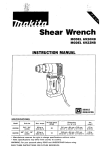
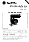
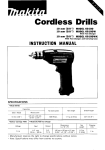
Rotarv Hammer
I
45 mm (1-3/4")
MODEL HR4500C
INSTRUCTION MANUAL
DOUBLE
INSULATION
SPECIFICATIONS
Capacities
Tungsten-carbide bit
1
Core bit
No load speed
IRPMI
Blows
per minute
1
* Manufacturer reserves the right to change specifications without notice.
* Note: Specifications may differ from country t o country.
WARNING: For your personal safety, READ and UNDERSTAND before using
SAVE THESE INSTRUCTIONS FOR FUTURE REFERENCE.
Overall
length
I
Net
weight
GENERAL SAFETY RULES
USA0021
(For All Tools)
WARNING! Read and understand all instructions. Failure
to follow all instructions listed below, may result in electric
shock, fire and/or serious personal injury.
SAVE THESE INSTRUCTIONS
Work Area
1. Keep your work area clean and well lit. Cluttered benches and dark areas invite
accidents.
2. Do not operate power tools in explosive atmospheres, such as in the presence
of flammable liquids, gases, or dust. Power tools create sparks which may
ignite the dust or fumes.
3.Keep bystanders, children, and visitors away while operating a power tool.
Distractions can cause you t o lose control.
Electrical Safetv
4.Double Insulated tools are equipped w i t h a polarized plug (one blade is wider
than the other.) This plug will fit in a polarized outlet only one way. If the
plug does not fit fully in the outlet, reverse the plug. If it still does not fit,
contact a qualified electrician t o install a polarized outlet. Do not change
the plug in any way. Double insulation I3 eliminates the need for the three
wire grounded power cord and grounded power supply system.
5.Avoid body contact with grounded surfaces such as pipes, radiators, ranges
and refrigerators. There is an increased risk of electric shock if your body is
grounded.
6 . Do not expose power tools t o rain or wet conditions. Water entering a power
tool will increase the risk of electric shock.
7 . Do not abuse the cord. Never use the cord t o carry the tools or pull the plug
from an outlet. Keep cord away from heat, oil, sharp edges or moving parts.
Replace damaged cords immediately. Damaged cords increase the risk of
electric shock.
8 . When operating a power tool outside, use an outdoor extension cord marked
“ W - A ‘ or “W.” These cords are rated for outdoor use and reduce the risk
of electric shock.
Personal Safety
9. Stay alert, watch what you are doing and use common sense when operating
a power tool. Do not use tool while tired or under the influence of drugs,
alcohol, or medication. A moment of inattention while operating power tools
may result in serious personal injury.
IO. Dress properly. Do not wear loose clothing or jewelry. Contain long hair. Keep
your hair, clothing, and gloves away from moving parts. Loose clothes, jewelry
or long hair can be caught in moving parts.
2
11. Avoid accidental starting. Be sure switch is off before plugging in. Carrying
tools w i t h your finger on the switch or plugging in tools that have the switch
o n invites accidents.
12. Remove adjusting keys or wrenches before turning the tool on. A wrench
or a key that is left attached t o a rotating part of the tool may result in personal
injury.
13. Do not overreach. Keep proper footing and balance at all times. Proper footing
and balance enables better control of the tool in unexpected situations.
14. Use safety equipment. Always wear eye protection. Dust mask, non-skid
safety shoes, hard hat, or hearing protection must be used for appropriate
conditions.
Tool Use and Care
15. Use clamps or other practical way t o secure and support the workpiece t o
a stable platform. Holding the work by hand or against your body is unstable
and may lead to loss of control.
16. Do not force tool. Use the correct tool for your application. The correct tool
will do the job better and safer at the rate for which it is designed.
17. Do not use tool if switch does not turn it on or off. Any tool that cannot
be controlled with the switch is dangerous and must be repaired.
18. Disconnect the plug from the power source before making any adjustments,
changing accessories, or storing the tool. Such preventive safety measures
reduce the risk of starting the tool accidentally.
19. Store idle tools out of reach of children and other untrained persons. Tools
are dangerous in the hands of untrained users.
20. Maintain tools w i t h care. Keep cutting tools sharp and clean. Properly
maintained tools, with sharp cutting edges are less likely to bind and are easier
to control.
21. Check for misalignment or binding of moving parts, breakage of parts, and
any other condition that may affect the tools operation. If damaged, have
the tool serviced before using. Many accidents are caused by poorly
maintained tools.
22. Use only accessories that are recommended by the manufacturer for your
model. Accessories that may be suitable for one tool, may become hazardous
when used on another tool.
SERVlCE
23. Tool service must be performed only by qualified repair personnel. Service
or maintenance performed by unqualified personnel could result in a risk of
injury.
24. When servicing a tool, use only identical replacement parts. Follow
instructions in the Maintenance section of this manual. Use of unauthorized
parts or failure t o follow Maintenance Instructions may create a risk of electric
shock or injury.
3
Specific Safety Rules
USBOlO 1
1. Hold tools by insulated gripping surfaces when performing an operation
where the cutting tool may contact hidden wiring or its o w n cord. Contact
with a "live" wire will make exposed metal parts of the tool "live" and shock
the operator.
2. Wear ear protectors when using the tool for extended periods. Prolonged
exposure to high intensity noise can cause hearing loss.
3.Wear a hard hat (safety helmet), safety glasses and/or face shield. It is also
highly recommended that you wear a dust mask and thickly padded gloves.
4. Be sure the bit is secured in place before operation.
5. Under normal operation, the tool is designed t o produce vibration. The screws
can come loose easily, causing a breakdown or accident. Check tightness
of screws carefully before operation.
6. In cold weather or when the tool has not been used for a long time, l e t the
tool warm up for a while by operating it under no load. This will loosen up
the lubrication. Without proper warm-up, hammering operation is difficult.
7. Always be sure you have a firm footing.
Be sure no one is below when using the tool in high locations.
8. Hold the tool firmly w i t h both hands.
9. Keep hands away from moving parts.
10.'Do not leave the tool running. Operate the tool only when hand-held.
11. Do not point the tool at any one in the area when operating. The bit could
fly out and injure someone seriously.
12. Do not touch the bit or parts close t o the bit immediately after operation;
they may be extremely hot and could burn your skin.
SAVE THESE INSTRUCTIONS.
4
SYMBOLS
The followings show the symbols
used for tool.
V
.................................
volts
A
.................................
amperes
Hz
.................................
herts
%
.................................
alternating current
n,
.................................
no load speed
El
.................................
Class II Construction
.../min
................................
revolutions or reciprocation per minute
LI=,
.................................
number of blow
5
FUNCTIONAL DESCRIPTION
Selecting action mode
Rotation with hammering
For drilling in concrete, masonry, etc.,
depress the lock button and rotate the
change lever so that the pointer points to
the
symbol. Use a tungsten carbidetipped bit.
Jy
E 1
Pointer
Hammering only
For chipping, scaling or demolition operations, depress the lock button and rotate the
symbol. Use a bull point, cold chisel,
change lever so that the pointer points to the
scaling chisel, etc.
Change lever
I
1 rPoin
I
CAUTION:
Do not rotate the change lever when the tool is running under load. The tool will be damaged.
*To avoid rapid wear on the mode change mechanism, be sure that the change lever is
always positively located in one of the two action mode positions.
The bit can be secured at 16 different
angles. To change the bit angle, depress
the lock button and rotate the change lever
so that the pointer points to the o symbol.
Turn the bit to the desired angle.
Lock button
Change lever
?ea
Pointer
6
Depress the lock button and rotate the
change lever so that the pointer points to
the
symbol. Then make sure that the bit
is securely held in place by turning it slight-
Change lever
Pointer
-,
ly.
Side handle
CAUTION:
Use the side handle only when chipping,
scaling or demolishing. Do not use it when
drilling in concrete, masonry, etc. The tool
cannot be held properly with this side handle when drilling.
The side handle can be swung 360" on the
vertical and secured at any desired position.
It also secures at eight different positions
back and forth on the horizontal. Just
loosen the clamp nut to swing the side handle to a desired position. Then tighten the
clamp nut securely.
Tighten
Side grip
CAUTION:
Always use the side grip to ensure operating safety when drilling in concrete, masonry,
etc.
The side grip swings around to either side,
allowing easy handling of the tool in any
position. Loosen the side grip by turning it
counterclockwise, swing it to the desired
position and then tighten it by turning clockwise.
7
Switch action
CAUTION:
Before plugging in the tool, always check
to see that the switch trigger actuates
properly and returns to the "OFF" position
when released.
To start the tool, simply pull the trigger.
Release the trigger to stop.
Speedchange
The revolutions and blows per minute can be adjusted just by turning the adjusting dial.
The dial is marked 1 (lowest speed) to 6
(full speed). Refer to the table below for
the relationship between the number settings on the adjusting dial and the revolutions/blows per minute.
Adjusting dial Number on
adjusting dial
6
5
4
3
2
1
Revolutions
per minute
240
230
200
Blows
per minute
2,550
2,450
2,100
160
1,700
130
120
1,300
1.250
Depth gauge
The depth gauge is convenient for drilling
holes of uniform depth. Loosen the clamp
screw and adjust the depth gauge to the
desired depth. After adjusting, tighten the
clamp screw firmly.
Clamp screw
7
NOTE:
The depth gauge cannot be used at the position where the depth gauge strikes against
the gear housing/motor housing.
8
indicator lamp
The green power-ON indicator lamp lights up when the tool is switched ON. If the indicator lamp is lit but the tool does not start,
Service
the carbon brushes may be worn out, or
indicator lamp
the electric circuit or the motor may be
defective. If the indicator lamp does not
T P o w e r - O N indlcator lamp (green)
light up and the tool does not start, the
ON/OFF switch or the mains cord may be
defective.
The red service indicator lamp lights up
when the carbon brushes are nearly worn
out to indicate that the tool needs servicing.
After approx. 8 hours of use, the motor will
automatically be shut off.
ASSEMBLY
Installing or removing bit
CAUTION:
Always be sure that the tool is switched off and unplugged before installing or removing
the bit.
Clean the bit shank and apply the bit grease
provided to it before installing the bit.
-
Bit shank
Insert the bit into the tool. Turn the bit and
push it in until it engages.
9
If the bit cannot be pushed in, remove the
bit. Pull the chuck cover down a couple of
times. Then insert the bit again. Turn the
bit and push it in until it engages.
After installing, always make sure that the
bit is securely held in place by trying to pull
it out. To remove the bit, pull the chuck
cover down all the way and pull the bit out.
10
OPERATION
Hammer drilling operation
Set the change lever to theufl symbol.
Position the bit at the location for the hole,
then pull the trigger.
Do not force the tool. Light pressure gives
best results. Keep the tool in position and
prevent it from slipping away from the hole.
Do not apply more pressure when the hole
becomes clogged with chips or particles.
Instead, run the tool at an idle, the remove
from the hole. By repeating this several
times, the hole will be cleaned out.
CAUTION:
When the bit begins to break through concrete or if the bit strikes reinforcing rods embedded in concrete, the tool may react dangerously. Maintain good balance and safe footing while holding the tool firmly with both hands to prevent dangerous reaction.
Torque limiter
The torque limiter will actuate when a certain torque level is reached. The motor will disengage from the output shaft. When this happens, the bit will stop turning.
CAUTION:
As soon as the torque limiter actuates, switch off the tool immediately. This will help prevent premature weak of the tool.
Chipping/Scaling/Demolition
Set the change lever to the symbol. Hold
the tool firmly with both hands. Turn the
tool on and apply slight pressure on the tool
so that the tool will not bounce around,
uncontrolled. Pressing very hard on the tool
will not increase the efficiency.
11
MAINTENANCE
CAUTION:
Always be sure that the tool is switched off and unplugged before attempting to perform
inspection or maintenance.
Replacing carbon brushes
When the resin insulating tip inside the carbon brush is exposed to contact the commutator, it will automatically shut off the
motor. When this occurs, both carbon
brushes should be replaced at the same
time. Use only identical carbon brushes.
7r
Insulating tip
1
Use a screwdriver to remove the brush
holder cover.
Carbon brush
K
Screwdriver
Brush holder cover
Use a screwdriver to remove the brush
holder caps. Take out the worn carbon
brushes, insert the new ones and secure
the brush holder caps.
Screwdriver
Brush holdei
12
Lubrication
CAUTION:
This servicing should be performed by Makita Authorized or Factory Service Centers only.
This tool required no hourly or daily lubrication because it has a grease-packed lubrication system. It should be relubricated
after every 6 months of operation. Send the
complete tool to Makita Authorized or
Factory Service Center for this lubrication
service. However, if circumstances require
that you should lubricate it by yourself, proceed as follows.
Run the tool for several minutes to warm it
up. Switch off and unplug the tool.
Loosen the six screws and remove the handle. Note that the top screws are different
from other screws.
Screws -
Disconnect the connector by pulling it
Remove the crank cap using a hex wrench.
Cramp
Ipac
IHex wrench
13
Rest the tool on the table with the bit end pointing upwards. This will allow the old grease
to collect inside the crank housing. Wipe out the old grease inside and replace with a fresh
grease (60 9). Use only Makita genuine hammer grease (optional accessory). Filling with
more than the specified amount of grease (approx. 60 g) can cause faulty hammering
action or machine failure. Fill only with the specified amount of grease. Reinstall the crank
cap and tighten with the hex wrench.
Connect the connector and reinstall the handle.
Hammer grease
.
White
CAUTION:
Be careful not to damage the terminal or lead wires especially when wiping out the old
grease of installing the handle.
Do not tighten the crank cap excessively. It is made of resin and is subject to breakage.
To maintain product SAFETY and RELIABILITY, repairs, any other maintenance or adjustment should be performed by Makita Authorized or Factory Service Centers, always using
Makita replacement parts.
14
ACCESSORIES
-
CAUTION
These accessories or attachments are recommended for use with your Makita tool specified in this
manual The use of any other accessories or attachments might present a risk of injury to persons
The accessories or attachments should be used only in the proper and intended manner
-
Safety goggle
Part No. 191686-2
Bit grease (100 g)
Part No. 181573-3
Side handle
Part No 134915-0
Part No. 181490-7
Side grip
Carrying case
Part No. 134916-8
Part No. 824607-6
Hammer grease (30gl
Depth gauge
Part No. 321248-4
15
WARNING
Some dust created by power sanding, sawing, grinding, drilling, and other
construction activities contains chemicals known [to the State of California] to
cause cancer, birth defects or other reproductive harm. Some examples of
these chemicals are:
0 Lead from lead-based paints,
0 Crystalline silica from bricks and cement and other masonry products, and
0 Arsenic and chromium from chemically-treatedlumber.
Your risk from these exposures varies, depending on how often you do this
type of work. To reduce your exposure to these chemicals: work in a well
ventilated area, and work with approved safety equipment, such as those
dust masks that are specially designed to filter out microscopic particles.
MAKITA LIMITED ONE YEAR WARRANTY
Warranty Policy
Every Makita tool is thoroughly inspected and tested before leaving the factory. It is warranted to
be free of defects from workmanship and materials for the period o f ONE YEAR from the date of
original purchase. Should any trouble develop during this one-year period, return the COMPLETE
tool, freight prepaid, to one of Makita’s Factory or Authorized Service Centers. If inspection shows
the trouble is caused by defective workmanship or material, Makita will repair (or at our option,
replace) without charge.
This Warranty does not apply where:
repairs have been made or attempted by others:
repairs are required because of normal wear and tear:
The tool has been abused, misused or improperly maintained;
alterations have been made to the tool.
IN NO EVENT SHALL MAKITA BE LIABLE FOR ANY INDIRECT, INCIDENTAL OR CONSEQUENTIAL DAMAGES FROM THE SALE OR USE O F THE PRODUCT. THIS DISCLAIMER
APPLIES BOTH DURING AND AFTER THE TERM O F THlS WARRANTY.
MAKITA DISCLAIMS LIABILITY w n A N Y I h w L i t D WARRANTIES. I N C L U D I V GI M P L I L D
WARRANTIFS OF “MFRCHANTABILITY” AND “CITNtSS I OR A SPFClClC PURPOSL.”
AFTER THE ONE-YFAR T t R M O F THIS WARRANTY
This Warranty gives you specific legal rights, and you may also have other rights which vary from
state to state. Some states do not allow the exclusion or Limitation of incidental or consequential
damages, so the above limitation or exclusion may not apply to you. Some states d o not allow
limitation o n how long an implied warranty lasts, so the above limitation may not apply to you.
P
Makita Corporation
3-11-8, Sumiyoshi-cho,
Anjo, Aichi 446-8502 Japan
aa4367~064
PRINTED IN JAPAN
2001-7N