1
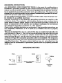
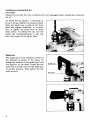
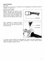
13 mm (1/2")
MODEL D A 6 3 0 0
2-Speed
INSTRUCTION MANUAL
Drilling capacities
No load
speed
Wood
Auger-bit
High
Low
Ship-auger bit
29 mm
(1-1/8")
38 mm
(1-1/2")
38
(1
- 1 /2")
(1 -1/2")
38 mm
Steel
(RPMI
13 mm
(112")
1,200
Overall length
Net
weight
Self-feed bit
35 mm
(1 -3/8")
18
(4-5/8")
330 m m (13")
4.3 kg
0410 mm (16-3/16") 19.5lbsl
300
Extended spade grip
Manufacturer reserves t h e r i g h t t o change specifications w i t h o u t notice.
Note: Specifications m a y differ f r o m c o u n t r y t o country.
IMPORTANT
SAFETY INSTRUCTIONS
(For All Tools)
WARNING: WHEN UStNG ELECTRIC TOOLS, BASIC SAFETY PRECAUTIONS SHOULD ALWAYS BE FOLLOWED TO
REDUCE THE RISK OF FIRE, ELECTRIC SHOCK, AND PERSONAL INJURY, INCLUDING THE FOLLOWING:
READ ALL INSTRUCTIONS.
1. KEEP WORK AREA CLEAN. Cluttered areas and benches invite injuries.
2. CONSIDER WORK AREA ENVIRONMENT. Don't use power tools in damp
or wet locations. Keep work area well lit. Don't expose power tools t o rain.
Don't use tool in presence of flammable liquids or gases.
3. KEEP CHILDREN AWAY. All visitors should be kept away from work area.
Don't let visitors contact tool or extension cord.
4. STORE IDLE TOOLS. When not in use, tools should be stored in dry, and high
or locked-up place - out of reach of children.
5. DON'T FORCE TOOL. It will do the job better and safer at the rate for which
it was intended.
6. USE RIGHT TOOL. Don't force small tool or attachment t o do the job of a
heavy-duty tool. Don't use tool for purpose not intended.
7 . DRESS PROPERLY. Don't wear loose clothing or jewelry. They can be caught
in moving parts. Rubber gloves and non-skid footwear are recommended
when working outdoors. Wear protective hair covering to contain long hair.
8 . USE SAFETY GLASSES. Also use face or dust mask if cutting operation is
dusty.
9. DON'T ABUSE CORD. Never carry tool by cord or yank it to disconnect from
receptacle. Keep cord from heat, oil, and sharp edges.
IO. SECURE WORK. Use clamps or a vise t o hold work. It's safer than using
your hand and it frees both hands t o operate tool.
11. DON'T OVERREACH. Keep proper footing and balance at all times.
12. MAINTAIN TOOLS WITH CARE. Keep tools sharp and clean for better and
safer performance. Follow instructions for lubricating and changing accessories. Inspect tool cords periodically and if damaged, have repaired by authorized service facility. Inspect extension cords periodically and replace if
damaged. Keep handles dry, clean, and free from oil and grease.
13. DISCONNECT TOOLS. When not in use, before servicing, and when changing accessories, such as blades, bits, cutters.
2
14. REMOVE ADJUSTING KEYS AND WRENCHES. Form habit of checking t o
see that keys and adjusting wrenches are removed from tool before turning
it on.
15. AVOID UNINTENTIONAL STARTING. Don't carry plugged-in tool with finger
on switch. Be sure switch is OFF when plugging in.
16. OUTDOOR USE EXTENSION CORDS. When tool is used outdoors, use only
extension cords intended for use outdoors and so marked.
17. STAY ALERT. Watch what you are doing, use common sense. Don't operate
tool when you are tired.
18. CHECK DAMAGED PARTS. Before further use of the tool, a guard or other
part that is damaged should be carefully checked t o determine that it will
operate properly and perform its intended function. Check for alignment of
moving parts, binding of moving parts, breakage of parts, mounting, and any
other conditions that may affect its operation. A guard or other part that
is damaged should be properly repaired or replaced by an authorized service
center unless otherwise indicated elsewhere in this instruction manual. Have
defective switches replaced by authorized service center. Don't use tool if
switch does not turn it on and off.
19. GUARD AGAINST ELECTRIC SHOCK. Prevent body contact w i t h grounded
surfaces. For example; pipes, radiators, ranges, refrigerator enclosures.
20. PROPER GROUNDING. This tool should be grounded while in use t o protect
the operator from electric shock.
21. EXTENSION CORDS: Use only three-wire extension cords which have threeprong grounding-type plugs and three-pole receptacles which accept the
tool's plug. Replace or repair damaged or worn cord immediately.
VOLTAGE WARNING: Before connecting the tool t o a power source (receptacle,
outlet, etc.) be sure the voltage supplied is the same as that specified on the
nameplate of the tool. A power source with voltage greater than that specified
for the tool can result in SERIOUS INJURY t o the user - as well as damage t o
the tool. If in doubt, DO NOT PLUG IN THE TOOL. Using a power source with
voltage less than the nameplate rating is harmful t o the motor.
3
GROUNDING INSTRUCTIONS
ALL GROUNDED, CORD-CONNECTED TOOLS: In the event of a malfunction or
breakdown, grounding provides a path of least resistance for electric current to
reduce the risk of electric shock. This tool is equipped w i t h an electric cord having an equipment-groundingconductor and a grounding plug. The plug must be
plugged into a matching outlet that is properly installed and grounded in accordance with all local codes and ordinances.
Do not modify the plug provided - i f it will not fit the outlet, have the proper outlet installed by a qualified electrician.
Improper connection of the equipment-grounding conductor can result in a risk
of electric shock. The conductor with insulation having an outer surface that is
green with or without yellow stripes is the equipment-grounding conductor. If
repair or replacement of the electric cord or plug is necessary, do not connect
the equipment-grounding conductor to a live terminal.
Check with a qualified electrician or serviceman if the grounding instructions are
not completely understood, or if in doubt as to whether the tool is properly
grounded.
This tool is intended for use on a circuit that has an outlet that looks like the
one illustrated in Figure A. The tool has a grounding plug that looks like the plug
illustrated in Figure A. A temporary adapter, which looks like the adapter illustrated in Figure B and C, may be used to connect this plug to a 2-pole receptacle
as shown in Figure B if a properly grounded outlet is not available. The temporary
adapter should be used only until a properly grounded outlet can be installed by
a qualified electrician. The green-colored rigid ear, lug, etc. extending from the
adapter must be connected to a permanent ground such as a properly grounded
outlet box.
GROUNDING METHODS
FIG. A
FIG. 0
FIG. C
Outlet Box
Grounding Pin
4
Grounding
Means
ADDITIONAL SAFETY RULES
1. Always be sure you have a firm footing.
Be sure no one is below when using the tool in high locations.
2. Hold the tool firmly.
3. Keep hands away from rotating parts.
4. When drilling into walls, floors or wherever "live" electrical wires may be
encountered, DO NOT TOUCH ANY METAL PARTS OF THE TOOL!
Hold the tool only by the plastic handle or the side grip t o prevent electric
shock if you drill into a "live" wire.
5. Do not leave the tool running. Operate the tool only when hand-held.
6. Do not touch the drill bit or the workpiece immediately after operation, they
may be extremely hot and could burn your skin.
SAVE THESE INSTRUCTIONS.
5
Installing or removing drill bit
CAUTION :
Always be sure that the tool is switched off and unplugged before installing or removing
the bit.
To install the bit, place it in the chuck as
far as it will go. Tighten the chuck by hand.
Place the chuck key in each of the three
holes and tighten clockwise. It is important to tighten the chuck with all three
holes evenly. To remove the bit, turn the
chuck key counterclockwise in just one
hole, then loosen the chuck by hand.
Spade grip
The spade grip can be installed in either of
the positions as shown in the figure. To
change the location of the spade grip from
one position to the other, loosen the hex
bolts with a wrench and turn the spade grip
to another position. Then tighten the hex
bolts securely.
I
6
I
Holding tool
CAUTION :
This is a powerful tool. High torque is developed and it is important that the tool be
securely held and properly braced.
Grasp the switch handle with one hand and the spade grip with the other hand. When
drilling a large hole with a hole saw, etc., the side grip (auxiliary handle) should be used
as a brace to maintain safe control of the tool. When drilling action i s forward (clockwise),
the tool should be braced tightly to prevent a counterclockwise reaction if the bit should
bind. When reversing, brace the tool to prevent a clockwise reaction. If the bit must be
removed from a partially drilled hole, be sure the tool i s properly braced before reversing.
Switch action
The switch is reversible, providing either
clockwise or counterclockwise rotation.
To start the tool, simply pull the lower part
of the switch for clockwise, the upper part
for counterclockwise. Release the switch to
Counterclockwise
stop.
CAUTION :
Before plugging in the tool, always check to see that the switch actuates properly and
returns to the "OFF" position when released.
0
Change the direction of rotation only when the tool comes to a complete stop. Changing it before the tool stops may ruin the tool.
7
DrilIing operation
0 Drilling in wood
When drilling holes in the wood, use a wood drill with a guide screw. The guide screw
makes it bore naturally by itself, so you do not need to apply any pressure to the tool.
0
Drilling in metal
To prevent the bit from slipping when starting a hole, make an indentation with a centerpunch and hammer a t the point to be drilled. Place the point of the bit in the indentation and start drilling.
Use a cutting lubricant when drilling metals. The exceptions are iron and brass which
should be drilled dry.
CAUTION :
.Pressing excessively on the tool will not speed up the drilling. In fact, this excessive
pressure will only serve to damage the tip of your bit, decrease the tool performance
and shorten the service life of the tool.
0 There i s a tremendous force exerted on the tool/bit a t the time of hole break through.
Hold the tool firmly and exert care when the bit begins to break through the workpiece.
*Always grip the small workpiece firmly with a vise or a holding means.
.A stuck bit can be removed simply by setting the reversing switch to reverse rotation
in order to back out. However, the tool will pull away easily unless you hold it firmly
before starting the tool.
8
MAINTENANCE
CAUTION :
Always be sure that the tool is switched off and unplugged before attempting to perform
inspection or maintenance.
Replacing carbon brushes
Remove and check the carbon brushes
regularly. Replace when they wear down
to the limit mark. Keep t h e carbon brushes
clean and free to slip in the holders. Both
carbon brushes should be replaced a t the
same time. Use only Makita carbon brushes.
/
Limit mark
Use a screwdriver to remove the brush
holder caps. Take out the worn carbon
brushes, insert the new ones and secure the
brush holder caps.
To maintain product SAFETY and RELIABILITY, repairs, any other maintenance or
adjustment should be performed by Makita Authorized or Factory Service Centers,
always using Makita replacement parts.
9
ACC ESSOR I ES
CAUTION :
These accessories or attachments are recommended for use with your Makita tool specified in this
manual. The use of any other accessories or attachments might present a risk of injury to persons. The
accessories or attachments should be used only in the proper and intended manner.
0
Hole saw
79 mm (3-1/8") Part No. 714202-9
95 mm (3-3/4') Part No. 714201-1
carrying case
Part No. 823122-7
0 Steel
10
0
Chuck key S13
Part No. 763206-8
June-26-90
@”
US
13 mm (1/2”)
ANGLE DRILL
Model DA6300
Note: The switch. noise suppressor and other part conflguratloli\
may differ from country to country
11
June
MODEL D A 6 3 0 0
ITEM
1
2
3
4
5
6
7
6
9
10
11
12
13
14
15
16
17
18
19
20
21
22
23
24
26
27
28
29
G:D
DESCRIPTION
6
4
1
1
1
1
1
1
1
1
1
1
1
1
1
1
1
1
1
1
2
1
1
1
1
1
2
1
30
3
31
32
2
2
33
1
Pan Head Screw M5x25 IWiIh Warherl
Rwet 0 - 5
Name Plate
Housing Cover
Needle Bearing 1010
Spur Gear 33
Sleeve 26
spur G ~ . V28
Needle Bearing 610
Gear Complete 1 0 - 4 5
Ball Bearing 608LB
Rubber Pin 4
Ball Bearing 627L8
Rubber Pin 4
Gear Complete 1 2 - 5 9
Ball Bearing 626L8
Rubber Pin 4
Slider
Housing
Pan Head Screw M4x6 IWith Washerl
Pan Head Screw M5x14 (With Washer)
Handle Set [With Item 291
Cord
Cord Guard
Switch
Strain Relief
Pan Head Screw M4x18 [With Washer1
Handle Set IWlth Item 221
Pan Head Screw M4x22 [With Warherl
Pan Head Screw M5x14 IWith Washer)
Insulation Washer
FIELD ASSEMBLY
34
1
35
I
36
31
38
1
1
2
39
1
40
41
42
43
44
45
46
41
48
49
50
51
52
53
54
1
1
1
1
4
1
1
1
1
1
1
1
1
2
2
1
1
1
1
1
1
55
56
57
58
59
60
61
2
2
62
63
-
1
26-90
US
DESCRIPTION
Baffle Plate
Ball Bearing 6000LLB
Rubber Pin 4
Dus1 Seal 1 0
Pan Head Screw M5r60 (With Washer & Bond1
ARMATURE ASSEMBLY
[With Item 35 3 1 4 0 & 411
Fan 70
Ball Bearing 608LB
Rubber Pin 4
Bearing BOX
Pan Head Screw M 5 r 2 2 IWith Washerl
Flat Head Screw M 6 r 2 6
Spring Washer 6
Drill Chuck 5 1 3
Spindle
Pin 6
Bearing Retainer 23-36
Ball Bearing 6003LLB
Retaining Ring S - 1 1
Brush Holder Cap 6 - 10
Carbon Brush
stopper P,”
Compression Spring 6
Slide Button
PI”
Sleeve 5
Pan Head Screw M5x14 IWith Washer]
Hex Bolt Max25 IWith Washer)
Flat Washer 8
Grip
-
Note The switch and ofher par1 Speclficalioni may differ from country to c o u n l r ~
r
1
MAKlTA LIMEDONE YEAR WARRANTY
Warranty Policy
Every Makita tool IS thoroughly mspected and tested before leaving the factory. It is wananted to
be free of defects from workmanship and materials for the period of ONE YEAR from the date of
original purchase. Should any trouble develop during this one-year period, return the COMPLETE
twl, freight prepaid, to one of Makita’s Factory or Authorized Serfice Centers. If inspection shows
the trouble io caused by defective workmanship or material, Makita will repair (or at our option,
replace) wthout charge.
Tlur Warranty does not apply where:
repsrs have been made or attempted by othcrs:
repairs are required because of normal wear and tear:
The tool has been abused, misused or improperly maintained;
alterations have been made to the tool.
I N NO tVFNT SHALL MAKITA BF LIABLE FOR A N Y INDIRFCT. INCIDENTAL OR CONStQUtNTlAL DAMAGES FROM THF SALt OR USF Ob THE PRODUCT THIS DISCLAIMtR
APPLIES BOTH DURING AND AITER T H t T t R M OF THIS WARRANTY
MAKITA DISCLAIMS LIABILITY FOR ANY IMPLIED WARRANTIFS. INCLUDING lMPLlt0
WARRAhWES Of. “MFRCHANTABILITY” AND “FITNESS FOR A SPECIFIC PURPOSE.”
A r T b R THE ONt-Y EAR TtRM OF T H I S WARRANTY
Ths Warranty p e r you specific legdl @IS. and you may d50 have other nghtr which vary from
state t o sate Some s l i t ~ sdo not allow the c x e l u ~ i ~orn Ismitition of incidental or conwqucniml
damages. IO the above IUniUlion or CXCIUIIOII
may not apply to YOU Some states do not allow
W
€ L U & & k ~ , U .
11-8,3-chome, Sumiyorhi-cho. Anjo, Aichi 446, Japan
883743 - 069
PRINTED IN JAPAN
1990 - 8 - N