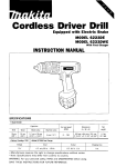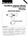
1
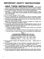
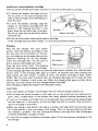
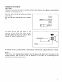
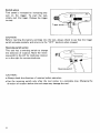
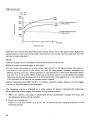
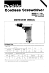
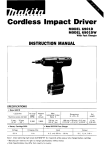
Cordless Impact Driver
Equipted with Electric Brake
MODEL 6911D
MODEL 6911DW
With Fast Charger
INSTRUCTION MANUAL
capamttes
4 mm
-
8 mm 15/32"
No load s p e e d
Standard bolt
M a c h i n e screw
~
5/16")
5 mm
12 m m 13/16"
112"l
1
(RPMI
High tensile bolt
5 mm
-
1 0 m m 13/16"
~
318")
0
~
1,800
Impacts per minute
M a x fastening torque
(See note 1 below1
Dimensions
1L x W x HI
Net wesght
0 - 2.500
1 , 0 0 0 kg.cm 171 f t lbsl
2 2 1 mm x 7 9 m m x 230 mm
18~314"x 3 118'' x 9 " l
1.8 kg 14 0 lbsl
*
Battery Cartridge 1200
Voltage
12
v
Model DC1290 Fast Charger
Input
I
AConlv50Hr-60Hz
I
OUtPUt
I
D C 9 6 V 1 2 V
Charging time
I
1 Hr
Note 1. After fastening high tensile bolt M14 (F1 1 T l for 3 seconds whlle using a fully charged battery cartridge
2 . Manufacturer reserves the right to change specifications without notice.
3. Specifications may differ from country t o country.
IMPORTANT
SAFETY INSTRUCTIONS
(For All Tools)
WARNING: WHEN USING ELECTRIC TOOLS, BASIC SAFETY
PRECAUTIONS SHOULD ALWAYS BE FOLLOWED TO REDUCE
THE RISK OF FIRE, ELECTRIC SHOCK, AND PERSONAL
INJURY, INCLUDING THE FOLLOWING:
READ ALL INSTRUCTIONS.
1. KEEP WORK AREA CLEAN. Cluttered areas and benches invite injuries.
2. CONSIDER WORK AREA ENVIRONMENT. Don't use power tools in damp
or wet locations. Keep work area well lit. Don't expose power tools t o rain.
Don't use tool in presence of flammable liquids or gases.
3. KEEP CHILDREN AWAY. All visitors should be kept away from work area.
Don't let visitors contact tool or extension cord.
4.STORE IDLE TOOLS. When not in use, tools should be stored in dry, and high
or locked-up place - out of reach of children.
5 . DON'T FORCE TOOL. It will do the job better and safer at the rate for which
it was intended.
6. USE RIGHT TOOL. Don't force small tool or attachment t o do the job of a
heavy-duty tool. Don't use tool for purpose not intended.
7 . DRESS PROPERLY. Don't wear loose clothing or jewelry. They can be caught
in moving parts. Rubber gloves and non-skid footwear are recommended
when working outdoors. Wear protective hair covering t o contain long hair.
8 . USE SAFETY GLASSES. Also use face or dust mask if cutting operation is
dusty.
9. DON'T ABUSE CORD. Never carry tool by cord or yank it t o disconnect from
receptacle. Keep cord from heat, oil, and sharp edges.
IO. SECURE WORK.
Use clamps or a vise t o hold work. It's safer than using
your hand and it frees both hands t o operate tool.
11. DON'T OVERREACH. Keep proper footing and balance at all times.
12. MAINTAIN TOOLS WITH CARE. Keep tools sharp and clean for better and
safer performance. Follow instructions for lubricating and changing accessories. Inspect tool cords periodically and if damaged, have repaired by authorized service facility. Inspect extension cords periodically and replace if
damaged. Keep handles dry, clean, and free from oil and grease.
13. DISCONNECT TOOLS. When not in use, before servicing, and when changing accessories, such as blades, bits, cutters.
2
14. REMOVE ADJUSTING KEYS AND WRENCHES. Form habit of checking t o
see that keys and adjusting wrenches are removed from tool before turning
it on.
15. AVOID UNINTENTIONAL STARTING. Don‘t carry plugged-in tool with finger
on switch. Be sure switch is OFF when plugging in.
16. OUTDOOR USE EXTENSION CORDS. When tool is used outdoors, use only
extension cords intended for use outdoors and so marked.
17. STAY ALERT. Watch what you are doing, use common sense. Don’t operate
tool when you are tired.
18. CHECK DAMAGED PARTS. Before further use of the tool, a guard or other
part that is damaged should be carefully checked t o determine that it will
operate properly and perform its intended function. Check for alignment of
moving parts, binding of moving parts, breakage of parts, mounting, and
any other conditions that may affect its operation. A guard or other part
that is damaged should be properly repaired or replaced by an authorized
service center unless otherwise indicated elsewhere in this instruction
manual. Have defective switches replaced by authorized service center. Don’t
use tool if switch does not turn it on and off.
19. GUARD AGAINST ELECTRIC SHOCK. Prevent body contact w i t h grounded
surfaces. For example; pipes, radiators, ranges, refrigerator enclosures.
20. REPLACEMENT PARTS. When servicing, use only identical replacement parts.
VOLTAGE WARNING: Before connecting the tool t o a power source (receptacle,
outlet, etc.) be sure the voltage supplied is the same as that specified on the
nameplate of the tool. A power source w i t h voltage greater than that specified
for the tool can result in SERIOUS INJURY t o the user - as well as damage t o
the tool. If in doubt, DO NOT PLUG IN THE TOOL. Using a power source w i t h
voltage less than the nameplate rating is harmful t o the motor.
3
IMPORTANT SAFETY INSTRUCTIONS
I.
SAVE THESE INSTRUCTIONS - This manual
Length of Cord (Feet)
25
50
AWG Size of Cord
18
18
100
18
150
16
9. Do not operate charger w i t h damaged cord or plug - replace them immediately.
IO. Do
not operate charger if it has received a sharp blow, been dropped, or
otherwise damaged in any way; take it t o a qualified serviceman.
11. Do not disassemble charger or battery cartridge; take it t o a qualified
serviceman when service or repair is required. Incorrect reassembly may
result in a risk of electric shock or fire.
12.To reduce risk of electric shock, unplug charger from outlet before attempting any maintenance or cleaning. Turning off controls will not reduce this risk.
4
ADDITIONAL SAFETY RULES
FOR CHARGER & BATTERY CARTRIDGE
1. Do not charge Battery Cartridge when temperature is BELOW 10°C (5O0F1
or ABOVE 4OoC ( 1 0 4 O F ) .
2. Do not attempt to use a step-up transformer, an engine generator or DC power
receptacle.
3. Do not allow anything t o cover or clog the charger vents.
4. Always cover the battery terminals w i t h the battery cover when the battery
cartridge is not used.
5. A battery short can cause a large current flow, overheating, possible burns
and even a breakdown.
( 11 Do not touch the terminals w i t h any conductive material.
(2) Avoid storing battery cartridge in a container with other metal objects such
as nails, coins, etc.
(3)Do not expose battery cartridge t o water or rain.
6. Do not store the tool and Battery Cartridge in locations where the temperature may reach or exceed 5OoC (122OF).
7. Do not incinerate the Battery Cartridge even if it is severely damaged or is
completely worn out. The battery cartridge can explode in a fire.
ADDITIONAL SAFETY RULES
1. Be aware that this tool is always in an operating condition, because it does
not have t o be plugged into an electrical outlet.
2. Wear ear protectors.
3. Hold the tool firmly.
4. Always be sure you have a firm footing.
Be sure no one is below when using the tool in high locations.
5. When driving into walls, floors or wherever "live" electrical wires may be
encountered, DO NOT TOUCH ANY METAL PARTS OF THE TOOL!
Hold the tool only by the insulated grasping surfaces t o prevent electric shock
if you drive into a "live" wire.
SAVE THESE INSTRUCTIONS.
5
Installing or removing battery cartridge
Always switch off the tool before insertion or removal of the battery cartridge.
0
*To remove the battery cartridge, pull out
the set plate on the tool and grasp both
sides of the cartridge while withdrawing it
from the tool.
*To insert the battery cartridge, align the
tongue on the battery cartridge with the
groove in the housing and slip it into
place. Snap the set plate back into place.
Be sure to close the set plate fully before
using the tool.
0
Battery cartridge
1
Do not use force when inserting the battery cartridge.
If the cartridge does not slide in easily, it is not being inserted correctly.
Charging
Plug the fast charger into your power
source. Insert the battery cartridge so that
the plus and minus terminals on the batCharging light
tery cartridge are on the same sides as their
respective markings on the fast charger.
Start b u t t o n
Insert the cartridge fully into the port so
that it rests on the charger port floor.
Press the start button (red). The charging
light will come on and charging will begin.
l f t h e charging light does not come on, press the reset button (yellow) first, then the start
button (red). If the charging light goes out within 10 seconds even after pressing the
reset button and start button a couple of times, the battery cartridge is dead. (CAUTION : Wait for more than 5 seconds after the charging light goes out to press the reset
button again.) Replace it with a new one. When the charging light goes out after about
one hour, you may remove the fully charged battery cartridge.
After charging, unplug the charger from the power source.
CAUTION :
0 Your new battery cartridge is not charged. You will need t o charge it before use.
.Do not keep the button pressed in with tape, etc. or the circuit will not function properly. Also, a malfunction of the charger may result possibly causing overheating, etc.
0 If you try to charge a cartridge from a just-operated tool, sometimes the charging light
will not come on. If this occurs, l e t the cartridge cool off for a while. Then re-insert it
and try to charge it once more.
0 When you charge a new battery cartridge or a battery cartridge which has not been used
for a long period, it may not accept a full charge. This i s a normal condition and does
not indicate a problem. You can recharge the battery cartridge fully after discharging
it almost completely a couple of times.
0 If you wish to charge two battery cartridges, allow 15 minutes between chargings on the
fast charger.
6
Use only the driver bit or socket bit shown
in the figure.
Do not use any other driver bit or socket
11 mm
(7/16")
bit.
9 mm
(3/8")
To install the bit, pull the sleeve in the
direction of the arrow and insert the bit
into the sleeve as far as it will go. Then
release the sleeve to secure the bit.
Sleeve
To remove the bit, pull the sleeve in the direction of the arrow and pull the bit out firmly.
NOTE :
If the bit i s not inserted deep enough into the sleeve, the sleeve will not return to i t s
original position and the bit will not be secured. In this case, try re-inserting the bit
according to the instructions above.
7
Switch action
Tool speed i s increased by increasing pressure on the trigger. To start the tool,
simply pull the trigger. Release the trigger
to stop.
CAUTION :
Before inserting the battery cartridge into the tool, always check to see that the trigger
switch actuates properly and returns to the "OFF" position when released.
Reversing switch action
This tool has a reversing switch to change
the direction of rotation. Move the reversing switch to the left for clockwise rotation
or to the right for counterclockwise.
CAUTION :
0 Always check the direction of rotation before operation.
*Use the reversing switch only after the tool comes to a complete stop. Changing the
direction of rotation before the tool stops may damage the tool.
8
Operation
The proper fastening torque may differ depending upon the kind or size of the screw, the
type of material to be fastened, etc. The relation between fastening torque and fastening
time i s shown in the figures below.
Machine screw
Kg . c m
( f t . Ibs)
200
M 8 x 12
(15)
(5/16” x 1/2”)
al
3
J
P
Proper fastening
fastening torque
torque
Proper
for M8 (5/16”)
c
p
100
‘E
(7)
4-VI
U
Proper fastening torque
f o r M6 ( 1/4”)
I
0
0.5
1
Seconds
Fastening time
Standard bolt
Kg . cm
( f t . Ibs)
800
T
(57)
2
0
e
+/
Y
.-P
Proper fastening torque
f o r MI 2 ( 1/2”)
C
Proper fastening torque
f o r M10 (3/8”)
t-
v
m
200
(15)
0
1
2
3
Proper fastening torque
f o r M8 (5/16”)
Proper fastening torque
for M6 (1/4”)
Seconds
Fastening time
9
High tensile bolt
Kg . cm
( f t . Ibs)
800
(57)
600
m
3
torque
(43)
P
E!
._
?
400
(29)
C
c
(u
Proper fastening torque
for M8 ( 5 / 1 6 ' )
m
200
(15)
0
1
2
3
Seconds
Fastening time
Hold the tool firmly and place the point of the driver bit in the screw head. Apply forward pressure to the tool to the extent that the bit will not slip off the screw and turn the
tool on to start operation.
NOTE :
Use the proper bit for the head of the screw that you wish to use.
0
Hold the tool pointed straight a t the screw.
0
If you fasten the screw for a time longer than shown in the figures above, the screw or
the screw or the point of the driver. bit may be overstressed, stripped, damaged, etc.
Before starting your job, always perform a test operation to verify the adequate fastening time for your screw. When fastening a machine screw in a steel plate, the proper
fastening torque can be obtained in an extremely short time (approx. 0.1 -0.2 seconds).
Turn the tool off as soon as the impact sound i s heard.
.When fastening screw M8 (5/16')or smaller, carefully adjust pressure on the trigger
switch so that the screw is not damaged.
The fastening torque i s affected by a wide variety of factors including the following.
After fastening, always check the torque with a torque wrench.
1. When the battery cartridge is discharged almost completely, voltage will drop and
the fastening torque will be reduced.
2. Drive bit or socket bit
Failure to use the correct size driver bit or socket bit will cause a reduction in the
fastening torque.
10
3. Bolt
0
Even though the torque coefficient and the class of bolt are the same, the proper
fastening torque will differ according to the diameter of the bolt.
.Even though the diameters of bolts are the same, the proper fastening torque will
differ according to the torque coefficient, the class of bolt and the bolt length.
4. The type of materials to be fastened and the manner of holding the tool will affect the
torque.
5. Operating the tool a t low speed will cause a reduction in the fastening torque.
CAUTION :
If the tool i s operated continuously until the battery cartridge has discharged, allow the
tool to rest for 15 minutes before proceeding with a fresh battery.
11
MAINTENANCE
CAUTION :
Always be sure that the tool is switched off and the battery cartridge is removed before
attempting to perform inspection or maintenance.
To maintain product SAFETY and RELIABILITY, repairs, maintenance or adjustment
should be performed by Makita Authorized or Factory Service Centers, always using
Makita replacement parts.
12
ACCESSORIES
CAUTION:
These accessories or attachments are recommended for use with your Makita tool specified in this
manual. The use of any other accessories or attachments might present a risk of injury t o persons.
The accessories or attachments should be used only in the proper and intended manner.
-
Bits
Size
Part No.
Phillips
Battery cartridge 1200
Part No. 632268-6
Fast charger
Model DC1290
Part No. 11 3 1 19-7
7 8 4 2 1 5-OA
Battery cover
Part No. 414938-7
Plastic carrying case
Part No. 182523-1
13
A m -14-'92
EN
CORDLESS IMPACT DRIVER
Model 6911D
Note: The switch and other part configurations
may differ from country to country.
14
MODEL 6911D
'itM$,,
Apr-14-
DESCRIPTION
AtD
",',:I
9 2 EN
DESCRIPTION
MACHINE
___
1
8
9
10
1
6
1
1
1
1
1
1
1
1
27
1
1
11
1
Compression Spring 14
28
1
12
1
1
4
1
1
2
Sleeve
29
30
31
32
33
1
2
3
4
S
6
7
13
14
15
16
17
-
N o t e The s w i t c h
N a m e Plate
Tapping Screw B T 4 x 2 0
Pan Head Screw M a x 2 0 IWith Washer1
Houslnq Set IWith Item 291
s e t Plate
S w i t c h Lever
Swltch
18
19
20
29
21
1
22
1
23
24
2
1
L W W
25
1
Ring Spring 12
Flat Washer 1 4
26
Hammer Care
Tapping Screw 8 T 4 x 2 0
0 Ring SO
Flal Washer 18
Steel Ball 4
1
1
I
1
1
Anvil
Hammer
Steel Ball 3 5
Flat Washer 2 8
Compression Spring 30
Steel Ball 5 6
Spindle
DC Motor 12 v
Plane Bearing 4
Gear Complete 10 3 8
Plane Bearing 4
Hausing Set [With Item 41
Label
Baftery Holder
Battery 1 2 0 0
Hand Strap
and other part specifications may differ f r o m c o u n t r y to c o u n t r y
15
MAKITA LIMITED ONE YEAR WARRANTY
Warranty Policy
Every Makita tool is thoroughly inspected and tested before leaving the factory. It is warranted to
be free of defects from workmanship and materials for the period of ONE YEAR from the date of
original purchase. Should any trouble develop during this one-year period, return the COMPLETE
tool, freight prepaid, to one of Makita’s Factory or Authorized Service Centers. If inspection shows
the trouble is caused by defective workmanship or material, Makita will repair (or at our option,
replace) without charge.
This Warranty does not apply where:
repairs have been made or attempted by others:
repairs are required because of normal wear and tear:
The tool has been abused, misused or improperly maintained;
e alterations have been made to the tool.
I N NO tVFNT SHALL MAKITA B t LIABLL 1 OR A Y Y INDIRtCT, INCIDFNTAL OR CONSI OlJtNTlAL DAMAGtS I ROM TIIL SALL OR US1 Ob THF PRODUCT TIIIS DlSCLAlMLR
APPLIES BOTH DURING AND AFTER THE TERM O F THIS WARRANTY.
MAKITA DISCLAIMS LIABILITY FOR ANY IMPLIED WARRANTIES, INCLUDING IMPLIED
WARRANTIES OF “MERCHANTABILITY” AND “FITNESS FOR A SPECIFIC PURPOSE,”
AFTER THE ONE-YEAR TERM O F THIS WARRANTY.
This Warranty gjves you specific legal rights, and you may also have other rights which vary from
state to state. Some states do not allow the exclusion or limitation of incidental or consequential
damages, so the above limitation or exclusion may not apply to you. Some states do not allow
limitation on how long an implied warranty lasts, so the above limitation may not apply to you.
Makita Corporation
3-11-8, Sumiyoshi-cho,
Anjo, Aichi 446 Japan
883809 - 065
PRINTED IN JAPAN
1992 - 7 - N