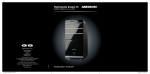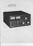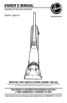
1
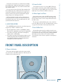
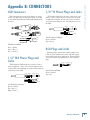
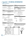
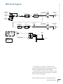
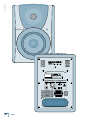
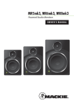
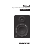
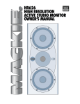
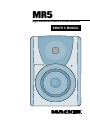
.3 High Resolution Active Studio Monitor >F=4A½B<0=D0; MR5 IMPORTANT SAFETY INSTRUCTIONS 1. Read these instructions. 13.Unplug this apparatus during lightning storms or when unused for long periods of time. 2. Keep these instructions. 3. Heed all warnings. 4. Follow all instructions. 5. Do not use this apparatus near water. 6. Clean only with dry cloth. Use a non-scratch cloth to protect the finish. 7. Do not block any ventilation openings. Install in accordance with the manufacturer’s instructions. 8. Do not install near any heat sources such as radiators, heat registers, stoves, or other apparatus (including amplifiers) that produce heat. 9. Do not defeat the safety purpose of the polarized or grounding-type plug. A polarized plug has two blades with one wider than the other. A grounding-type plug has two blades and a third grounding prong. The wide blade or the third prong are provided for your safety. If the provided plug does not fit into your outlet, consult an electrician for replacement of the obsolete outlet. 10.Protect the power cord from being walked on or pinched particularly at plugs, convenience receptacles, and the point where they exit from the apparatus. 11.Only use attachments/accessories specified by the manufacturer. 12.Use only with a cart, stand, tripod, bracket, or table specified by the manufacturer, or sold with the apparatus. When a cart is used, use caution when moving the cart/apparatus combination to avoid injury from tip-over. PORTABLE CART WARNING Carts and stands - The Component should be used only with a cart or stand that is recommended by the manufacturer. A Component and cart combination should be moved with care. Quick stops, excessive force, and uneven surfaces may cause the Component and cart combination to overturn. CAUTION AVIS RISK OF ELECTRIC SHOCK DO NOT OPEN RISQUE DE CHOC ELECTRIQUE NE PAS OUVRIR CAUTION: TO REDUCE THE RISK OF ELECTRIC SHOCK DO NOT REMOVE COVER (OR BACK) NO USER-SERVICEABLE PARTS INSIDE REFER SERVICING TO QUALIFIED PERSONNEL ATTENTION: POUR EVITER LES RISQUES DE CHOC ELECTRIQUE, NE PAS ENLEVER LE COUVERCLE. AUCUN ENTRETIEN DE PIECES INTERIEURES PAR L'USAGER. CONFIER L'ENTRETIEN AU PERSONNEL QUALIFIE. AVIS: POUR EVITER LES RISQUES D'INCENDIE OU D'ELECTROCUTION, N'EXPOSEZ PAS CET ARTICLE A LA PLUIE OU A L'HUMIDITE The lightning flash with arrowhead symbol within an equilateral triangle is intended to alert the user to the presence of uninsulated "dangerous voltage" within the product's enclosure, that may be of sufficient magnitude to constitute a risk of electric shock to persons. Le symbole éclair avec point de flèche à l'intérieur d'un triangle équilatéral est utilisé pour alerter l'utilisateur de la présence à l'intérieur du coffret de "voltage dangereux" non isolé d'ampleur suffisante pour constituer un risque d'éléctrocution. The exclamation point within an equilateral triangle is intended to alert the user of the presence of important operating and maintenance (servicing) instructions in the literature accompanying the appliance. Le point d'exclamation à l'intérieur d'un triangle équilatéral est employé pour alerter les utilisateurs de la présence d'instructions importantes pour le fonctionnement et l'entretien (service) dans le livret d'instruction accompagnant l'appareil. MR5 14.Refer all servicing to qualified service personnel. Servicing is required when the apparatus has been damaged in any way, such as powersupply cord or plug is damaged, liquid has been spilled or objects have fallen into the apparatus, the apparatus has been exposed to rain or moisture, does not operate normally, or has been dropped. 15.This apparatus shall not be exposed to dripping or splashing, and no object filled with liquids, such as vases, shall be placed on the apparatus. 16.This apparatus has been designed with Class-I construction and must be connected to a mains socket outlet with a protective earthing connection (the third grounding prong). 17.Note that this apparatus is not completely disconnected from the AC mains service when the power switch is in the OFF position. 18.This apparatus does not exceed the Class A/Class B (whichever is applicable) limits for radio noise emissions from digital apparatus as set out in the radio interference regulations of the Canadian Department of Communications. ATTENTION — Le présent appareil numérique n’émet pas de bruits radioélectriques dépassant las limites applicables aux appareils numériques de class A/de class B (selon le cas) prescrites dans le réglement sur le brouillage radioélectrique édicté par les ministere des communications du Canada. 19.Exposure to extremely high noise levels may cause permanent hearing loss. Individuals vary considerably in susceptibility to noise-induced hearing loss, but nearly everyone will lose some hearing if exposed to sufficiently intense noise for a period of time. The U.S. Government’s Occupational Safety and Health Administration (OSHA) has specified the permissible noise level exposures shown in the following chart. According to OSHA, any exposure in excess of these permissible limits could result in some hearing loss. To ensure against potentially dangerous exposure to high sound pressure levels, it is recommended that all persons exposed to equipment capable of producing high sound pressure levels use hearing protectors while the equipment is in operation. Ear plugs or protectors in the ear canals or over the ears must be worn when operating the equipment in order to prevent permanent hearing loss if exposure is in excess of the limits set forth here. Duration Per Day In Hours Sound Level dBA, Slow Response 8 6 4 3 2 1.5 1 0.5 0.25 or less 90 92 95 97 100 102 105 110 115 Typical Example Duo in small club Subway Train Very loud classical music Home theater (loudest peaks) Loudest parts at a rock concert WARNING — To reduce the risk of fire or electric shock, do not expose this apparatus to rain or moisture. Owner’s Manual Contents IMPORTANT SAFETY INSTRUCTIONS............2 INTRODUCTION..................................................4 QUICK START.............................................................................5 REAR PANEL DESCRIPTION ..............................6 1. SIGNAL INPUTS................................................................ 6 2. INPUT LEVEL..................................................................... 6 3. HIGH FREQUENCY FILTER............................................. 6 4. LOW FREQ FILTER.............................................................7 5. Power Switch.....................................................................7 6. Mains Input and Fuse......................................................7 7. Bass Reflex Port.................................................................7 FRONT PANEL DESCRIPTION............................7 8. Power Indicator................................................................7 PROTECTION CIRCUITS......................................8 Overexcursion Protection................................................. 8 Thermal Protection............................................................ 8 Integrated Magnetic Shielding........................................ 8 Input Signal Wiring............................................................. 8 CARE AND CLEANING.........................................8 Appendix A: SERVICE INFO................................9 Troubleshooting.................................................................. 9 Repair.....................................................................................10 Appendix B: CONNECTORS.............................. 11 Appendix C: TECHNICAL INFORMATION....12 MR5 Specifications................................................................12 MR5 Block Diagram............................................................... 13 MR5 Limited Warranty.....................................15 • Please write the serial number for your studio monitor here (all studio monitors if you have more than one) for future reference (i.e., insurance claims, tech support, return authorization, etc.): Monitor 3 Monitor 1 Monitor 2 Purchased at:___________________________________ Date of Purchase:_____________ Don’t forget to visit our website at www.mackie.com for more information about this and other Mackie products. R Part No. SW0567 Rev. B 01/08 ©2007-2008 LOUD Technologies Inc. All Rights Reserved. Owner’s Manual MR5 INTRODUCTION Thank you for choosing the MR5 Mackie Reference Studio Monitors. Just as we revolutionized the studio monitor market with our flagship HR824 Studio Monitor, we have done it again with the most affordable precision active studio monitors ever made. The MR5 features design elements shared by our HR MK2 Series high resolution studio monitors, providing a level of performance never before available at this price. • The connecting wires between the amplifier outputs and the drivers are kept to an absolute minimum, so the damping factor of the amplifier isn’t compromised by the resistance of long speaker cables. Investments in Excellence... In short, all the complex interconnected components in the system are designed to work in harmony with each other to produce the best possible sound. The MR5s were designed by our expert loudspeaker and transducer engineering teams at Mackie and EAW. These compact studio monitors can be used in a variety of applications, including small project studios, surround sound editing, home theater playback, and desktop audio workstations (DAWs). High-frequency and low-frequency switches are provided on the rear panel to adjust the sound of the monitors to the characteristics of the room. Three types of input connectors are provided, XLR, 1/4-inch, and RCA, to interface with virtually any application you may have. The result? The MR5 Studio Monitors are extremely accurate and versatile, with unique controls that allow you to fine-tune the sound to match your individual environment precisely. You’re gonna love these! What are they? The Advantages... The MR5 Studio Monitors are two-way, bi-amplified, active monitors employing a bass reflex (ported) design for an extended low-frequency response. There are many benefits to integrating an active crossover, power amplifiers, and drivers into a single cabinet, and we’ve taken full advantage of these benefits in the design of the MR5. • The crossover point is designed so that the high- and low-frequency drivers are fed only the frequencies they are best able to reproduce. • The amplifiers are designed to provide maximum acoustic output from the speakers, yet minimize the danger of speaker damage due to overdriving. • In addition, the amplifiers’ gain and frequency responses are individually hand-trimmed to compensate for typical manufacturing tolerances between the drivers and produce a smooth frequency response from 60 Hz to 20 kHz. MR5 • The acoustic sum of the outputs from the two drivers are optimized electronically, as well as physically, so the amplitude response is unity and the phase difference is minimal. The Transducers... The MR5s feature a 5.25-inch high-precision, low-distortion woofer and a 1-inch high-resolution tweeter. The high-frequency driver is mounted on a molded baffle/waveguide, which reduces diffraction and results in wide, controlled dispersion of high-frequency sounds. This widens the “sweet spot” and improves the time domain characteristics of the system. The Cabinet... The cabinet is made of MDF with a matte-black finish. Internal bracing increases the strength and rigidity (stiffness) of the box. An open-cell adiabatic foam material fills the inside of the box to absorb internal reflections and dampen standing waves. Power Amplifiers... The low-frequency amplifier produces up to 55 watts continuous before clipping, while the high-frequency amplifier produces up to 30 watts continuous. Both amplifiers are Class A/B with power MOSFET outputs and active protection circuits. We realize that you can’t wait to hook up your new Mackie MR5 Studio Monitors and try them out. Nevertheless, please take the time to read this page NOW, and the rest can wait until you’re good and ready. 1. Turn the INPUT LEVEL [2] control on the back of the cabinet down (fully counterclockwise) before turning on the monitor for the first time. 2. Set the power switch [5] on the back panel off. This will prevent you from accidentally connecting a hot signal source to the monitor and getting a rude surprise. 3. Leave the High Freq [3] and Low Freq [4] Filter switches at their Normal positions. 4. Connect the line-level monitor signal from your mixer, preamp, or other signal source to the INPUT [1] jack on the MR5 Studio Monitor (1⁄4-inch PHONE, XLR, or RCA). 5. Connect the supplied AC power cord to the IEC socket [6] on the back of the monitor. Plug the other end into an AC outlet properly configured with the voltage corresponding to the markings next to the IEC socket. 6. Start your signal source (tape deck, CD, DAW, or whatever), but leave the master volume control on your mixer or preamp down. 7. Turn on the power switch [5] on the MR5. The power LED [8] on the front panel will illuminate. 6. Slowly turn up the INPUT LEVEL [2] control on the back of the monitor to its fully clockwise position (MAX). 7. Adjust the master volume on your mixer or preamp to a comfortably loud listening level. If the MR5 gets loud really fast, turn down the INPUT LEVEL control to its center position (12 o’clock) to provide more volume control on your mixer or preamp. Enjoy the silky smooth highs and authoritative, commanding lows of the MR5. Then read the rest of this manual. AN EXTREMELY IMPORTANT NOTE ON MR5 BASS RESPONSE AND YOUR CONTROL ROOM. Your new MR5s achieve their best bass response in a room that’s optimized for bass reproduction. A lot of factors can conspire to thwart the MR5s’ extended low frequency — including room shape, room volume and acoustical treatment. This is not a cop-out or an apology. It’s plain old physics in action. Luckily we’ve armed you with some compensating controls that you can use to optimize the frequency response of the speakers in your particular room. Consider the following: Owner’s Manual QUICK START Low-Frequency Response When you put your MR5s in a corner or up against walls, their bass characteristics change. The apparent loudness of the low frequencies increases when the monitors are placed close to a wall, and even more so when they are placed in a corner. If you have placed the monitors away from the walls and corners and you would like to hear a little more bass, try setting the LOW FREQ FILTER [4] switch to the +2 dB position to provide a gentle boost to the low frequencies (below 100 Hz). If it’s still not enough bass, try the +4 dB position to provide a little more bass boost. High-Frequency Response The MR5s are designed to provide a smooth frequency response throughout the mid and high range. Nevertheless, you may decide that you need a little more or a little less high frequencies in your monitors while you are mixing. The HIGH FREQ FILTER [3] switch provides a gentle boost or cut in the frequencies above 5 kHz. Remember that boosting the high frequencies in the monitors can result in a duller mix, while reducing the high frequencies can result in a brighter overall mix. Additional Tidbits of Wisdom • Never listen to loud music for prolonged periods. Please see the Safety Instructions on page 2 for information on hearing protection. • When you shut down your equipment, turn off the MR5 studio monitors first to prevent thumps and other noises generated by any upstream equipment from coming out the speakers. When powering up, turn on the monitors last. • Save the shipping box! You may need it someday, and you don’t want to have to pay for another one. • Save your sales receipt in a safe place. • Also record all MR5 serial numbers in the space provided on page 3, along with where and when you bought them. Owner’s Manual MR5 REAR PANEL DESCRIPTION This is where you connect your signal to the monitor, and make adjustments to the frequency response of the speakers to match the monitor’s location and your room’s environment. 2. INPUT LEVEL The MR5 expects a line-level signal at its input. Use this control to adjust the sensitivity of the input section according to the signal strength at its input. 1. SIGNAL INPUTS • The MR5 is designed to operate with a +4 dBu signal when the INPUT LEVEL control is in the MAX position (in other words, wide open). • Refer to the QUICK START section on page 5 for the level-setting procedure. There are three types of input connectors: XLR (balanced), 1/4-inch (balanced), and RCA (unbalanced). Since all three of them are connected together electrically, do not connect more than one signal at a time to the input jacks. 3. HIGH FREQUENCY FILTER • The XLR connector and 1/4-inch TRS (tip-sleeve-ring) connector accept a balanced signal while the RCA connector accepts an unbalanced signal. A balanced signal provides better noise rejection and is the preferred method, especially if using a cable longer than 20 feet (6 meters). • The 1/4-inch TRS jack can also accept an unbalanced signal from a 1/4-inch TS (tip-sleeve) plug. The connectors are wired as follows (per the AES/IEC standard): XLR TRS RCA Hot (+) Cold (–) Shield (Ground) Pin 2 Pin 3 Pin 1 Tip Ring Shield The HIGH FREQ switch tailors the overall highfrequency response by ±2 dB at 5 kHz and above. Leave this switch in the “0 (NORMAL)” position unless: • You want to subtly brighten or darken the sound of the speakers. • Perhaps you have hearing loss caused by too many nights in front of a double Marshall stack. • You just like to mix on the bright side or dull side. If your mixes consistently sound dull or dark when you listen elsewhere, this usually indicates that your monitors are too bright, relative to your normal hearing. A bit less high-frequency energy usually fixes this, and you can force the mix in this direction by reducing the high-frequency output of the monitors by using the –2 dB position of the switch. Tip — Shield See Appendix B: Connectors for more information on these connectors. DESIGNED BY MACKOIDS IN WOODINVILLE, WA, USA MANUFACTURED IN CHINA • FABRIQUE EN CHINE COPYRIGHT©2007 • "MACKIE" AND THE RUNNING MAN FIGURE ARE TRADEMARKS OF LOUD TECHNOLOGIES, INC. • PATENT PENDING. CAUTION! SERIAL / DATE CODE RISK OF ELECTRIC SHOCK DO NOT OPEN WARNING: TO REDUCE THE RISK OF FIRE OR ELECTRIC SHOCK, DO NOT EXPOSE THIS EQUIPMENT TO RAIN OR MOISTURE. DO NOT REMOVE COVER. NO USER SERVICEABLE PARTS INSIDE. REFER SERVICING TO QUALIFIED PERSONNEL. AVIS: RISQUE DE CHOC ELECTRIQUE - NE PAS OUVRIR INPUT RCA (UNBALANCED) SETTINGS XLR (BALANCED) HIGH FREQ FILTER INPUT TRS (BALANCED) –2dB +2dB 0 (NORMAL) LOW FREQ FILTER OFF MAX LEVEL +2dB +4dB 0 (NORMAL) ON CAUTION: REPLACE WITH THE SAME FUSE AND RATING. DISCONNECT SUPPLY CORD BEFORE CHANGING FUSE. THIS DEVICE COMPLIES WITH PART 15 OF THE FCC RULES FOR THE U.S. AND ICES-003, FOR CANADA. OPERATION IS SUBJECT TO THE FOLLOWING TWO CONDITIONS: (1) THIS DEVICE MAY NOT CAUSE HARMFUL INTERFERENCE, AND (2) THIS DEVICE MUST ACCEPT ANY INTERFERENCE RECEIVED, INCLUDING INTERFERENCE THAT MAY CAUSE UNDESIRED OPERATION. MR5 It’s a real rush to mix really loud. But remember that the resulting mix only sounds good when you play it at least that loud. However strange it may sound, mixes made at lower levels sound even better when played loud, perhaps even a bit bigger than life. Get that sound level meter out. Decide what level you’re going to mix at and use the meter to help keep you mixing at that level. Your ears will thank you, and your mixes will be better for it. 4. LOW FREQ FILTER The LOW FREQ switch tailors the overall low-frequency response by +2 dB or +4 dB at 100 Hz. • For most applications, use the “0 (NORMAL)” setting. This takes the equalization circuit out of the signal path. • If you want or need just a little extra low-frequency output, use the +2 dB setting. • If you want or need more low-frequency output, use the +4 dB setting. Remember how things work in reverse, so boosting the deep bass content on playback may actually decrease it in the final mix. 5. Power Switch Use this switch to turn on or off the MR5. When the power switch is turned on and the MR5 is plugged into an AC outlet, the power LED on the front of the monitor lights up to let you know the MR5 is ready to go. 6. Mains Input and Fuse Connect the power cord to this IEC socket securely, and plug the other end into your AC outlet. Make sure the AC outlet has the correct voltage indicated next to the IEC socket. Owner’s Manual Conversely, if your mixes are consistently too bright, then adding some additional high-frequency energy in the monitors satisfies your ears, and the resultant mix has less HF content. The fuse is located behind the fuse cover, at the bottom of the IEC socket. See the “Troubleshooting” section on page 9 for information about replacing the fuse. 7. Bass Reflex Port A bass reflex system uses the radiation from the rear of the woofer cone to extend the low-frequency response of the speaker. The size of the port is carefully designed with respect to the volume of the cabinet and the characteristics of the woofer to produce low-frequency extension. FRONT PANEL DESCRIPTION 8. Power Indicator The power indicator lights up when the power switch [5] on the back of the MR5 is turned on and AC power is available at the mains input [6]. Owner’s Manual MR5 PROTECTION CIRCUITS There are several protection mechanisms designed into the MR5 to safeguard the loudspeakers and amplifiers from inadvertent damage. CAUTION: The protection circuits are designed to prevent damage to the loudspeakers under reasonable and sensible conditions. Should you choose to ignore the warning signs (i.e., excessive distortion), you can still damage the speakers in the MR5 by overdriving them. Such damage is beyond the scope of the warranty. Overexcursion Protection A 12 dB/octave high-pass filter at 60 Hz just prior to the low-frequency amplifier prevents very low frequencies from being amplified. Excessive low-frequency energy below 60 Hz can damage the woofer by causing it to “bottom out,” also known as overexcursion, which is equivalent to a mechanical form of clipping. Thermal Protection All amplifiers produce heat. The MR5 is designed to be efficient both electrically and thermally. • If for some reason the heatsink gets too hot, a thermal switch activates and turns off the amplifier. This protection operates independently for the low-frequency and high-frequency amplifiers. Therefore, it is possible for only the low frequency or high frequency amplifier to shut down while the other remains on. • When the heatsink cools down to a safe temperature, the thermal switch resets and normal operation resumes. • If the heatsink temperature again gets too hot, the shutdown process repeats. Should this happen, make sure that airflow to the rear of the cabinet is not restricted. If the ambient air temperature is very warm, try pointing a small fan toward the heatsink to increase the airflow through the ventilation holes. Integrated Magnetic Shielding The MR5 contains drivers with large magnetic structures. The drivers’ magnets are shielded to help prevent the magnetic field from radiating out into the environment and playing havoc with computer monitors or TV screens. Unshielded speakers can cause distortion in both the shape and color of the picture if placed too close to a CRT (cathode ray tube). If you have a particularly sensitive computer monitor or TV screen, it may be necessary to move the speakers a few inches away. MR5 Input Signal Wiring You should use high-quality, shielded cable to connect the signal source to the SIGNAL INPUT jack [1] on the MR5. • For balanced signals, foil shielded cables, such as Belden 8451, 8761, or 9501 are commonly used for studio wiring. • Microphone cables work well for the XLR input. • The better the shield, the better the immunity from externally induced noise (like EMI and RFI). Route the cable away from AC power cords and outlets. These are common sources for hum in an audio signal. Wall warts and line lumps are especially insidious hum inducers! You can purchase quality cables from your Mackie dealer. • In certain home theater applications, it may be necessary to connect the speaker outputs from a stereo receiver to the inputs of the MR5, if the receiver doesn’t have preamp outputs or other line-level output connections. CAUTION: Do not attempt to connect a speaker output directly to the input of the MR5! Speaker levels are much higher than line levels and can damage the input circuitry in the MR5. You can, however, insert a speaker-level to line-level signal attenuator between the receiver’s speaker output and the HR624 MK2’s input. Your Mackie dealer may be able to help you find one, or you can build your own. CARE AND CLEANING Your Mackie Reference Studio Monitors will provide many years of reliable service if you follow these guidelines. • Avoid exposing the monitors to moisture. • Avoid exposure to extreme cold (below freezing temperatures). • Use a slightly damp cloth with a mild soap solution to clean the cabinets. Only do this when the power is turned off. Avoid getting moisture into any of the opeings of the cabinet, particularly where the drivers are located. If you think your Mackie product has a problem, please check out the following troubleshooting tips and do your best to confirm the problem. Visit the Support section of our website (www.mackie.com/support) where you will find lots of useful information such as FAQs, documentation, and user forums. You may find the answer to the problem without having to send your Mackie product away. Troubleshooting No Power • Our favorite question: Is it plugged in? • Make sure the power cord is securely seated in the IEC socket [6] and plugged all the way into the AC outlet. • Make sure the AC outlet is live (check with a tester or lamp). • Is the power [5] switch on the rear panel in the ON position? • Is the power indicator [8] on the front panel illuminated? If not, make sure the AC outlet is live. If so, refer to “No Sound” below. • If the power indicator is not illuminated, and you are certain that the AC outlet is live, it is possible the fuse has blown. To remove and replace the fuse: 1. Disconnect the power cord from the IEC socket. 2. Remove the fuse drawer by prying it open with a small screwdriver. It will slide all the way out. FUSE 3. Remove the fuse and replace it with an equivalenttype fuse. 115 VAC unit: 1.6 amp slo-blo (T 1.6 A H/250V) 230 VAC unit: 800 milliamp slo-blo (T 800 mA H/250V) 4. Replace the fuse drawer by pushing it all the way back into the IEC socket. If two fuses blow in a row, then something is very wrong. See the “Repair” section on the next page to find out how to proceed. No Sound • Is the power indicator [8] on the front panel illuminated? If not, refer to “No Power” above. • Is the INPUT LEVEL [2] control turned up? • Is the signal source turned up? Make sure the signal level from the mixing console (or whatever device immediately precedes the studio monitor) is high enough to produce sound. • If it’s a stereo pair, try switching them around. For example, if a left output is presumed dead, switch the left and right cords at the monitor end. If the problem switches sides, it’s not the monitor. It could be a bad cable, or no signal from the mixer. Owner’s Manual Appendix A: SERVICE INFO Bad Sound • Is the input connector plugged completely into the jack? If using a 1⁄4" plug, make sure it is plugged all the way in. • Is it loud and distorted? Reduce the signal level at the mixer. • If possible, listen to the signal source with headphones plugged into the preamp stage. If it sounds bad there, it’s not the monitor. • Too much bass or not enough bass? Move around the room and see if the bass response changes. It’s possible your listening position coincides with a room mode where the low frequencies either become exaggerated or nulled. If so, try moving the monitors to a different position, or moving your listening position. Noise/Hum/Buzz • Check the signal cable between the mixer and the monitor. Make sure all connections are secure. These problems usually produce crackling noises, hum, or buzz. • If connecting an unbalanced output to the MR5 balanced input, make sure the shield is connected to the unbalanced ground of the source and to pins 1 and 3 of the XLR. • If a CATV cable is connected to the system, try disconnecting it. If the hum goes away, call your cable carrier to check for proper grounding of the cable. • Make sure the signal cable is not routed near AC cables, power transformers, or other EMI sources (including wall warts and line lumps!). These sources usually produce hum. • Is there a light dimmer or other triac-based device on the same AC circuit as the monitor? Dimmers cause buzzing noises. Use an AC line filter or plug the monitor into a different AC circuit. • Excessive hiss is an indication of an incorrect gain setting somewhere before the speaker. • If possible, listen to the signal source with headphones plugged in. If it sounds noisy there, it’s not the monitor. Owner’s Manual MR5 Repair For warranty repair or replacement, refer to the warranty information on page 15. Non-warranty repair for Mackie products is available at a factory-authorized service center. To locate your nearest service center, visit www.mackie.com, click “Support” and select “Locate a Service Center.” Service for Mackie products living outside the United States can be obtained through local dealers or distributors. If you do not have access to our website, you can call our Tech Support department at 1-800-898-3211, MondayFriday, 7 am to 5 pm Pacific Time, to explain the problem. Tech Support will tell you where the nearest factoryauthorized service center is located in your area. Need help with your new MR5? • Visit www.mackie.com and click Support to find: FAQs, manuals, addendums, and user forums. • Email us at: [email protected]. • Telephone 1-800-898-3211 to speak with one of our splendid technical support representatives, (Monday through Friday, from 7 am to 5 pm PST). 10 MR5 XLR Connectors 1/4" TS Phone Plugs and Jacks XLR connectors are used to make balanced connections to the MR5. They are wired as follows, according to standards specified by the AES (Audio Engineering Society). “TS” stands for Tip-Sleeve, the two connections available on a mono 1/4" phone jack or plug. They are used for unbalanced signals. It is okay to connect an unbalanced 1/4" phone plug into the 1/4" TRS phone jack on the MR5. 2 SHIELD HOT SLEEVE 1 3 COLD SLEEVE TIP 1 SHIELD TIP Owner’s Manual Appendix B: CONNECTORS TIP SLEEVE COLD 3 HOT 1 3 2 SHIELD COLD 2 HOT XLR Balanced Wiring Pin 1 = Shield Pin 2 = Hot (+) Pin 3 = Cold (–) 1/4" TS Unbalanced Wiring: Sleeve = Shield Tip = Hot (+) RCA Plugs and Jacks 1/4" TRS Phone Plugs and Jacks “TRS” stands for Tip-Ring-Sleeve, the three connections available on a stereo 1/4" or balanced phone jack or plug. TRS jacks and plugs are used to make balanced connections to the MR5. RING SLEEVE SLEEVE RING TIP RCA-type plugs (also known as phono plugs) and jacks are often used in home stereo and video equipment and in many other applications. They are unbalanced and electrically equivalent to a 1/4" TS phone plug. SLEEVE TIP SLEEVE TIP RCA Unbalanced Wiring: Sleeve = Shield Tip = Hot TIP RING TIP SLEEVE 1/4" TRS Balanced wiring: Sleeve = Shield Tip = Hot (+) Ring = Cold (–) Owner’s Manual 11 MR5 Appendix C: TECHNICAL INFORMATION MR5 Specifications Acoustic Performance Equalization Free Field Frequency Response: 60 Hz – 20 kHz (±3 dB) Low Frequency EQ: +2 dB/+4 dB @ 100 Hz, shelving High Frequency EQ: ±2 dB @ 5 kHz, shelving Lower Cutoff Frequency: –3 dB @ 60 Hz Upper Cutoff Frequency: –3 dB @ 22 kHz AC Power Requirements Sound Pressure Level @ 1 meter, +4 dBu into Balanced Input: 100 dB SPL @ 1m Maximum SPL Per Pair: 113 dB SPL @ 1m Transducers Low Frequency: 5.25 in/133 mm with steel frame, blue polypropylene cone woofer with rubber surround High Frequency: Wave guide loaded 1 in/25 mm silk dome tweeter Amplifiers Low Frequency Power: 55 watts, 4 ohm load, 85 watts peak High Frequency Power: 30 watts, 4 ohm load, 50 watts peak Slew Rate: > 15 V/µs 120 VAC, 60 Hz 240 VAC, 50 Hz 220 VAC, 60 Hz 100 VAC, 50/60 Hz Note: The MR5 does not support multiple voltage configurations. Make sure the voltage rating for your particular model (as indicated on the rear panel near the IEC socket) corresponds with your local AC mains voltage. AC Connector: 3-pin IEC 250 VAC, 16 A male Fuse: 115 VAC: T 1.6AL/250 V 230 VAC: T 800 mA/250 V Power Consumption: 75 watts with music, loud mix 10 watts quiescent (idle) Physical Dimensions and Weight Distortion (THD, SMPTE IMD, DIM 100): < 0.035% Signal-to-Noise Ratio: Low Frequency: > 101 dB, 20 Hz to 20 kHz, unweighted, referenced to 55 watts into 4 ohms High Frequency: > 93 dB, 20 Hz to 20 kHz, unweighted, referenced to 30 watts into 4 ohms Type: US: Europe: Korea: Japan: Monolithic IC, Class AB with DMOS power stage Enclosure: 0.625 in/16 mm thick MDF with 0.750 in/19 mm MDF front panel Damping: Adiabatic foam Dimensions: Height: Width: Depth: Weight: 11.25 in/286 mm 11.50 in/292 mm including top of waveguide 7.75 in/197 mm 10.50 in/266 mm 14.3 lb/6.5 kg Electronic Crossover Crossover Type: 24 dB/octave Crossover Frequency: 4 kHz Sensitivity: +4 dBu at 300 Hz for full output Input Impedance: 20 kΩ, balanced bridging; 10 kΩ unbalanced Disclaimer 7.75" (197 mm) LOUD Technologies is always striving to improve our products by incorporating new and improved materials, components and manufacturing methods. Therefore, we reserve the right to change these specifications at any time without notice. 10.50" (266 mm) MR5 WEIGHT 14.3 lb (6.5 kg) 11.50" (292 mm) 12 MR5 11.25" (286 mm) RCA UNBALANCED LINE INPUT XLR BALANCED LINE INPUT HI-FREQUENCY POWER AMPLIFIER HIGH FREQ 1 CROSSOVER +2 dB 0 –2 dB 2 3 INPUT LEVEL +HI VDC HI-FREQUENCY DRIVER HI-FREQ TWEET LO-FREQ 1/4" UNBALANCED LINE INPUT –HI VDC OVEREXCURSION PROTECT 60 Hz DARK SIDE OF THE MOON LO-FREQUENCY POWER AMPLIFIER LOW FREQ +HI VDC Owner’s Manual MR5 Block Diagram LO-FREQUENCY DRIVER +4 dB +2 dB 0 WOOF –HI VDC FUSE POWER POWER LED + HI VDC – MACKIE MR5 BLOCK DIAGRAM 08.29.07 TOROIDAL POWER TRANSFORMER + LO VDC – The following are trademarks or registered trademarks of LOUD Technologies Inc.: The Mackie logo, MR Series, Zero Edge Baffle, and the Running Man. This manual also contains names and marks of other companies which belong to those respective companies, and are hereby acknowledged. ©2007 LOUD Technologies Inc. All Rights Reserved. Owner’s Manual 13 MR5 DESIGNED BY MACKOIDS IN WOODINVILLE, WA, USA MANUFACTURED IN CHINA • FABRIQUE EN CHINE COPYRIGHT©2007 • "MACKIE" AND THE RUNNING MAN FIGURE ARE TRADEMARKS OF LOUD TECHNOLOGIES, INC. • PATENT PENDING. CAUTION! SERIAL / DATE CODE RISK OF ELECTRIC SHOCK DO NOT OPEN WARNING: TO REDUCE THE RISK OF FIRE OR ELECTRIC SHOCK, DO NOT EXPOSE THIS EQUIPMENT TO RAIN OR MOISTURE. DO NOT REMOVE COVER. NO USER SERVICEABLE PARTS INSIDE. REFER SERVICING TO QUALIFIED PERSONNEL. AVIS: RISQUE DE CHOC ELECTRIQUE - NE PAS OUVRIR INPUT RCA (UNBALANCED) SETTINGS XLR (BALANCED) HIGH FREQ FILTER INPUT TRS (BALANCED) –2dB +2dB 0 (NORMAL) LOW FREQ FILTER OFF MAX LEVEL +2dB +4dB 0 (NORMAL) ON CAUTION: REPLACE WITH THE SAME FUSE AND RATING. DISCONNECT SUPPLY CORD BEFORE CHANGING FUSE. THIS DEVICE COMPLIES WITH PART 15 OF THE FCC RULES FOR THE U.S. AND ICES-003, FOR CANADA. OPERATION IS SUBJECT TO THE FOLLOWING TWO CONDITIONS: (1) THIS DEVICE MAY NOT CAUSE HARMFUL INTERFERENCE, AND (2) THIS DEVICE MUST ACCEPT ANY INTERFERENCE RECEIVED, INCLUDING INTERFERENCE THAT MAY CAUSE UNDESIRED OPERATION. 14 MR5 Please keep your sales receipt in a safe place. A. LOUD Technologies Inc. warrants all materials, workmanship and proper operation of this product for a period of one year from the original date of purchase. You may purchase an additional 24-month Extended Warranty (for a total of 36 months of coverage). Visit our website and follow the “Product Registration” links for details (www.mackie.com). If any defects are found in the materials or workmanship or if the product fails to function properly during the applicable warranty period, LOUD Technologies, at its option, will repair or replace the product. This warranty applies only to equipment sold and delivered within the U.S. and Canada by LOUD Technologies Inc. or its authorized dealers. B. For faster processing (not to mention a free gift), register online or mail in the product registration card. C. Unauthorized service, repairs, or modification of Mackie products will void this warranty. To obtain repairs or replacement under warranty, you must have a copy of your sales receipt from the authorized Mackie dealer where you purchased the product. It is necessary to establish purchase date and determine whether your Mackie product is within the warranty period. D. To obtain warranty repair or replacement: 1. Call Mackie Technical Support at 800/898-3211, 7 AM to 5 PM Monday through Friday (Pacific Time) to get authorization for repair or replacement. Alternately, go to the Mackie website, click “Support” (www.mackie.com/ support), and follow the instructions for reporting a warranty issue and submitting a request for an advance replacement. 2. Advance Replacement: Mackie will ship a replacement unit to you along with an invoice for the suggested retail price of the replacement unit. You must return the defective unit immediately to cancel the invoice. If you do not return the defective unit within 30 days, you must pay the full amount stated in the invoice to satisfy your debt. 3. Repair: When you call Mackie Technical Support, explain the problem and obtain a Service Request Number. Have your Mackie product’s serial number ready. You must have a Service Request Number before you can obtain factoryauthorized service. • Pack the product in its original shipping carton. Also include a note explaining exactly how to duplicate the problem, a copy of the sales receipt with price and date showing, your daytime phone number and return street address (no P.O. boxes or route numbers, please!), and the Service Request Number. If we cannot duplicate the problem or establish the starting date of your Limited Warranty, we may, at our option, charge for service time and parts. • Ship the product in its original shipping carton, freight prepaid to the authorized service center. Write the Service Request Number in BIG PRINT on top of the box. The address of your closest authorized service center will be given to you by Technical Support, or it may be obtained from our website. Once it’s repaired, the authorized service center will ship it back by ground shipping, pre-paid (if it qualified as a warranty repair). Note: Under the terms of the warranty, you must ship or dropoff the unit to an authorized service center. The return ground shipment is covered for those units deemed by us to be under warranty. Note: You must have a sales receipt from an authorized Mackie dealer for your unit to be considered for warranty repair. IMPORTANT: Make sure that the Service Request Number is plainly written on the shipping carton. No receipt, no warranty service. E. LOUD Technologies reserves the right to inspect any products that may be the subject of any warranty claims before repair or replacement is carried out. LOUD Technologies may, at our option, require proof of the original date of purchase in the form of a dated copy of the original dealer’s invoice or sales receipt. Final determination of warranty coverage lies solely with LOUD Technologies. F. Any products returned to one of the LOUD Technologies factory-authorized service centers, and deemed eligible for repair or replacement under the terms of this warranty will be repaired or replaced. LOUD Technologies and its authorized service centers may use refurbished parts for repair or replacement of any product. Products returned to LOUD Technologies that do not meet the terms of this Warranty will not be repaired unless payment is received for labor, materials, return freight, and insurance. Products repaired under warranty will be returned freight prepaid by LOUD Technologies to any location within the boundaries of the USA or Canada. G. LOUD Technologies warrants all repairs performed for 90 days or for the remainder of the warranty period. This warranty does not extend to damage resulting from improper installation, misuse, neglect or abuse, or to exterior appearance. This warranty is recognized only if the inspection seals and serial number on the unit have not been defaced or removed. H. LOUD Technologies assumes no responsibility for the timeliness of repairs performed by an authorized service center. I. This warranty is extended to the original purchaser. This warranty may be transferred to anyone who may subsequently purchase this product within the applicable warranty period for a nominal fee. A copy of the original sales receipt is required to obtain warranty repairs or replacement. J. This is your sole warranty. LOUD Technologies does not authorize any third party, including any dealer or sales representative, to assume any liability on behalf of LOUD Technologies or to make any warranty for LOUD Technologies Inc. K. THE WARRANTY GIVEN ON THIS PAGE IS THE SOLE WARRANTY GIVEN BY LOUD TECHNOLOGIES INC. AND IS IN LIEU OF ALL OTHER WARRANTIES, EXPRESS AND IMPLIED, INCLUDING THE WARRANTIES OF MERCHANTABILITY AND FITNESS FOR A PARTICULAR PURPOSE. THE WARRANTY GIVEN ON THIS PAGE SHALL BE STRICTLY LIMITED IN DURATION TO ONE YEAR FROM THE DATE OF ORIGINAL PURCHASE FROM AN AUTHORIZED MACKIE DEALER. UPON EXPIRATION OF THE APPLICABLE WARRANTY PERIOD, LOUD TECHNOLOGIES INC. SHALL HAVE NO FURTHER WARRANTY OBLIGATION OF ANY KIND. LOUD TECHNOLOGIES INC. SHALL NOT BE LIABLE FOR ANY INCIDENTAL, SPECIAL, OR CONSEQUENTIAL DAMAGES THAT MAY RESULT FROM ANY DEFECT IN THE MACKIE PRODUCT OR ANY WARRANTY CLAIM. Some states do not allow exclusion or limitation of incidental, special, or consequential damages or a limitation on how long warranties last, so some of the above limitations and exclusions may not apply to you. This warranty provides specific legal rights and you may have other rights which vary from state to state. Owner’s Manual Owner’s Manual MR5 Limited Warranty 15 16220 Wood-Red Road NE • Woodinville, WA 98072 • USA United States and Canada: 800.898.3211 Europe, Asia, Central and South America: 425.487.4333 Middle East and Africa: 31.20.654.4000 Fax: 425.487.4337 • www.mackie.com E-mail: [email protected]