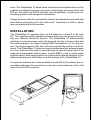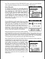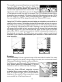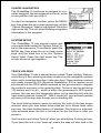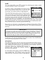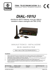
1
GlobalMap 12
INSTALLATION AND
OPERATION INSTRUCTIONS
TM
Copyright © 1996, 1997 Lowrance Electronics, Inc.
All rights reserved.
GlobalMap 12™ is a trademark of Lowrance Electronics, Inc.
Lowrance® is a registered trademark of Lowrance Electronics, Inc.
IMS SmartMap™ is a trademark of Lowrance Electronics, Inc.
WARNING!
USE THIS MAPPING UNIT ONLY AS AN AID TO NAVIGATION. A CAREFUL NAVIGATOR NEVER RELIES ON ONLY ONE METHOD TO OBTAIN POSITION INFORMATION.
Never use this product while operating a vehicle.
The background map built into this unit is not intended for navigation and
its accuracy has not been verified. This map is derived from U.S. government sources which rely on ground and aerial surveys and satellite data.
Since there can be inaccuracies in the data used to create the maps and
in the map’s resolution, plus position inaccuracies in the navigation system, use caution when using this product.
CAUTION
When showing navigation data to a position (waypoint), this unit will show
the shortest, most direct path to the waypoint. It provides navigation data
to the waypoint regardless of obstructions. Therefore, the prudent navigator will not only take advantage of all available navigation tools when travelling to a waypoint, but will also visually check to make certain a clear,
safe path to the waypoint is always available.
The storage temperature for your unit is from -4 degrees to +167 degrees
Fahrenheit (-20 to +75 degrees Celsius). Extended storage temperatures
higher or lower than specified will cause the liquid crystal display to fail.
Neither this type of failure nor its consequences are covered by the warranty. For more information, consult the factory customer service department.
All features and specifications subject to change without notice.
All screens in this manual are simulated. Many were taken with an IMS
SmartMap™ loaded into one of the cartridge slots.
INTRODUCTION .......................................................................................................... 1
INSTALLATION ............................................................................................................. 2
BATTERY INSTALLATION ............................................................................................ 3
ANTENNA ..................................................................................................................... 4
MAP CARTRIDGE INSTALLATION ............................................................................. 5
REMOVING MAP CARTRIDGE ................................................................................... 6
KEYBOARD .................................................................................................................. 6
OPERATION ................................................................................................................. 7
TURNING POWER ON ................................................................................................ 7
MENUS ......................................................................................................................... 7
FINDING YOUR POSITION .......................................................................................... 7
COLD START ............................................................................................................... 7
INITIALIZATION ........................................................................................................... 8
ENTER BY MAP ........................................................................................................... 8
ENTER MANUALLY ...................................................................................................... 10
POSITION/NAVIGATION DISPLAYS ........................................................................... 11
NAVIGATION SCREENS ............................................................................................. 12
CDI INDICATOR ........................................................................................................... 13
MAPPING SCREENS .................................................................................................. 14
MAP CURSOR ............................................................................................................. 15
AUTOZOOM ................................................................................................................. 16
EARTH MAP OPTIONS ............................................................................................... 17
C-MAP OPTIONS ......................................................................................................... 19
NAVIONICS OPTIONS ................................................................................................. 19
PLOTTER OPTIONS .................................................................................................... 21
ICONS .......................................................................................................................... 23
WINDOWS .................................................................................................................... 25
REPROGRAM WINDOW GROUPS ............................................................................. 25
SATELLITE INFORMATION SCREEN ......................................................................... 26
DUAL MAPPING ........................................................................................................... 27
CLOCK ......................................................................................................................... 27
TIMERS ........................................................................................................................ 29
REPROGRAM BOXES ................................................................................................. 30
WAYPOINT DATABASE ............................................................................................... 30
SAVING PRESENT POSITION AS A WAYPOINT (QUICK SAVE) ............................. 30
SAVING CURSOR POSITION AS A WAYPOINT ........................................................ 32
SAVING PRESENT POSITION AS A WAYPOINT (SELECT WAYPOINT #) .............. 32
SAVING CURSOR POSITION AS A WAYPOINT (SELECT WAYPOINT #) ............... 32
EDIT WAYPOINT LAT/LON .......................................................................................... 33
WAYPOINT NAMES ..................................................................................................... 33
WAYPOINT ICONS ...................................................................................................... 34
DELETE A WAYPOINT ................................................................................................ 34
MOVE A WAYPOINT .................................................................................................... 35
DISTANCE BETWEEN WAYPOINTS ........................................................................... 35
WAYPOINT OPTIONS .................................................................................................. 36
ROUTES ....................................................................................................................... 36
SELECT WAYPOINTS - WAYPOINT LIST ................................................................... 37
SELECT WAYPOINTS - FROM MAP ........................................................................... 38
FINISHING THE ROUTE .............................................................................................. 38
FOLLOWING A ROUTE ............................................................................................... 39
DELETE A ROUTE ....................................................................................................... 40
NAVIGATION ................................................................................................................ 40
NAVIGATE TO A WAYPOINT ....................................................................................... 40
NAVIGATE TO CURSOR POSITION ........................................................................... 41
NAVIGATE TO A WAYPOINT USING THE MAP ......................................................... 41
CANCEL NAVIGATION ................................................................................................ 42
SYSTEM SETUP .......................................................................................................... 42
TRACK HOLDING ........................................................................................................ 42
GPS CORRECTIONS .................................................................................................. 43
DATUM .......................................................................................................................... 43
PCF (POSITION CORRECTION FACTOR) ................................................................. 44
UNITS OF MEASURE .................................................................................................. 45
POSITION FORMAT .................................................................................................... 45
NMEA/DGPS ................................................................................................................ 46
SERIAL COMMUNICATION SETUP ............................................................................ 49
RESET OPTIONS ........................................................................................................ 49
RESET GROUPS ......................................................................................................... 49
SYSTEM INFO ............................................................................................................. 49
NAME INPUT ............................................................................................................... 50
GPS SETUP ................................................................................................................. 50
GPS UPDATE RATE/BATTERY SAVE ......................................................................... 51
POSITION PINNING .................................................................................................... 51
EXECUTE GPS SELF-TEST ....................................................................................... 51
EXECUTE GPS COLD START .................................................................................... 52
ALARMS ....................................................................................................................... 52
MESSAGES .................................................................................................................. 53
BACKLIGHT ................................................................................................................. 54
CONTRAST .................................................................................................................. 54
SPEAKER ON/OFF ...................................................................................................... 54
SIMULATOR ................................................................................................................. 55
BATTERIES .................................................................................................................. 56
DEFINITION OF TERMS/ABBREVIATIONS ............................................................... 57
WINDOW BOXES ......................................................................................................... 58
WINDOW GROUPS ..................................................................................................... 60
UPS RETURN POLICY ................................................................................................ 62
WARRANTY ................................................................................................................. 64
DATABASE LICENSE AGREEMENT ........................................................................... 65
DATABASES LIMITED WARRANTY ............................................................................ 66
HOW TO OBTAIN SERVICE - INTERNATIONAL .......................... INSIDE BACK COVER
HOW TO OBTAIN SERVICE - U.S.A. ONLY ................................................ BACK COVER
INTRODUCTION
Thank you for purchasing an Lowrance® GlobalMap 12™. With its large
LCD screen, easy to use menus, and outstanding performance, we think
you’ll be happy with this product for many years.
The GlobalMap 12 can be used for fishing, hiking, canoeing, offshore
boating, and just about any other ground-based activity. This product also
takes IMS SmartMap™, C-MAP™, and Navionics™ cartridges, which
show greater detail of land and hydrographic features.
Like most GPS receivers, your GlobalMap 12 doesn’t have a compass or
any other navigation aid built into it. It relies solely on the signals from the
satellites to determine its position. Speed, direction of travel, and distance
are all calculated from position information. Therefore, in order for it to
determine the direction you’re travelling, you must be moving, and the
faster - the better. This is not to say the unit won’t work at walking speeds
- it will. But the faster you travel, the easier it is for the unit to determine
your direction.
GPS works from satellites that transmit information to the world at very
high frequencies. One disadvantage to this frequency is that it’s “line-ofsight”. In other words, the signals don’t bounce around like your local
radio or television. If you don’t have a clear view of the sky, or if you’re
inside a metal building, the unit probably won’t be able to pick up the
signals from the satellites. This is common among all GPS receivers. We
have found that using this product inside a car is usually sufficiently close
to the windows and windshield that it works well. However, there is an
optional remote antenna bracket and cable (model PA-2) that lets you
mount the removable antenna on top of the dash, in case it’s required.
Another factor that influences the GPS’ position and navigation capabilities is called selective availability or SA. This is small errors purposefully
injected into the transmitted signal from the satellites. The government
does this to degrade the system’s accuracy to civilian and foreign users.
Even with SA, GPS is the most accurate navigation system ever invented
on such a large scale. The Government’s accuracy specification is 100
meters horizontally and 150 meters vertically 95% of the time. In other
words, the position shown on your GlobalMap 12 could be up to 100 meters
in any direction from your actual position, and the altitude could be plus or
minus 150 meters from what’s shown on the screen, 95% of the time.
One way around the S/A problem is to purchase a DGPS receiver and
connect it to your GlobalMap 12. A DGPS receiver (commonly called a
beacon receiver), picks up correction signals broadcast from ground sta
1
tions. The GlobalMap 12 takes these corrections and applies them to the
position and altitude screens, giving you much better accuracy. Even with
S/A on, and without a DGPS receiver, your GlobalMap 12 gives you outstanding position and navigation information.
Please sit down with the unit and this manual and familiarize yourself with
them before using this unit in the “real world”. A simulator is built in, which
lets you practice with the receiver.
INSTALLATION
The GlobalMap 12 operates from six AA batteries or from 6 to 35 volts
DC. The cigarette lighter adapter included with your unit plugs into virtually any vehicle’s electrical system. The GlobalMap 12 automatically
switches to external power when it’s plugged into the unit (provided that
the external power is a higher voltage than the batteries.) If, for any reason, the external power fails, the unit will automatically switch to the batteries. The GlobalMap 12 does not require batteries when external power
is in use, however they make a good backup in case of power failure. An
optional rechargeable battery pack, (model RBP-L) has a nickle-metal
hydride battery and charger built into a pack that’s almost identical to the
alkaline battery pack that slides onto the bottom of the GlobalMap 12.
An external antenna kit is also available (model PA-2) that allows the removable antenna to be mounted on a suction cup bracket up to four feet
away from the GPS receiver.
PA-2
RBP-L
2
BATTERY INSTALLATION
The GlobalMap 12 requires six AA batteries. We recommend DURACELL®
alkaline batteries, but other brands will work. You can use lithium batteries
which will last longer than alkaline batteries (but cost more) or rechargeable ni-cad batteries (won’t last as long as standard alkalines). Rechargeable alkaline batteries such as RayOVac® Renewals® will also work .
Do not use heavy-duty batteries or any battery other than the ones listed
above. Do not mix different types of batteries. (For example, don’t use
both alkaline and ni-cad batteries at the same time.)
To install the batteries, first turn the GlobalMap 12 so that it is facing you.
Now grasp the bottom part of the case and push it to the right until it
comes completely off the unit. The
bottom part of the case holds the
batteries. Next, push the battery
holder out the bottom of the battery
cover as shown below. Install each
battery with the negative end (-)
against the spring. The positive end
(+) of each battery should be firmly
against the metal plate. When all six
batteries are installed, slide the battery holder into the battery cover.
If the battery holder sticks when sliding into the battery cover, apply a
thin film of petroleum jelly to the “O”
rings on the battery holder.
3
IMPORTANT!
There are arrows molded into the bottom of the battery cover and battery
holder. Make certain the arrows are properly aligned! Otherwise, the battery holder won’t slide all the way into the cover and the battery pack
won’t slide onto the unit.
Slide the battery pack onto the unit and the GlobalMap 12 is ready for
use.
ANTENNA
Your GlobalMap 12 has a removable antenna that folds over the display
when the unit is not in use. This prevents damage to the display. To open
the antenna, simply lift on an edge and raise it to the desired position. The
antenna is a quick release design, simplifying its removal and installation.
To remove the antenna, push the antenna to the right (1), while simultaneously moving the antenna up (2), until it clears the AirMap's right side
(3). To replace the antenna, reverse the above steps. Make certain to
align the antenna with the GlobalMap 12 until the antenna slides into
place to the left by itself. When it does, the antenna has mated with the
connector inside the unit and it’s ready for use.
1.
2.
4
3.
MAP CARTRIDGE INSTALLATION
The GlobalMap 12 uses IMS SmartMap™ and WorldMap™, C-Map™,
and Navionics™ cartridges, all of which are packaged in a cartridge housing specifically designed for Lowrance mapping products.
The IMS SmartMap™ cartridges contain digitized data of over 120,000
bodies of water. Nearly all inland waterways-public and private lakes, rivers, and streams, plus coastal United States waters up to 25 miles out are
included. There are also state and U.S. interstate highways and routes,
cities and towns. These inland mapping cartridges cover the entire continental United States in 64 highly detailed cartridges. The WorldMap™
cartridges cover all other areas of the world, showing more detail than the
background map, but not as much as the SmartMap™ areas.
The Navionics and C-Map cartridges cover most of the world with detailed views of coastal and some inland waters. Over 600 cartridges are
available.
LEI
IMS
TEX
NOR AS
TH
LEI
LEI
IMS
OKL
AHO
EAS MA
T
IMS
AME
DAT RICAS
ABA
SE
LEI
IMS
OKL
AHO
EAS MA
T
To install a cartridge into the GlobalMap 12, first make certain the unit is
turned off. Never install or remove a cartridge with the unit turned
on! You can damage your unit if you install or remove a cartridge with the
unit turned on. Next, pry the cover off the back of the unit. Place the cartridge into either slot with it’s label facing you as shown at the bottom of
the previous page. Now slide the cartridge towards the top until it stops.
Replace the cover.
5
REMOVING A CARTRIDGE
If you have difficulty removing a cartridge, use the back cover as a removal tool. Simply press one side of the cover against the ridge on the
cartridge and gently push towards the bottom of the unit. Don’t use a
corner of the cover - it could damage it.
KEYBOARD
The keyboard has twelve keys. The arrow keys are tied to most of the
features, letting you easily move the mapping cursor, navigate through
the menus, make selections from menus, and other tasks.
PAGES
WPT
MENU
EXIT
Z-OUT
Z-IN
ENT
PWR
The WPT key lets you create, save, and recall waypoints and routes. The
PAGES key switches the unit between the three major displays: windows,
navigation, and mapping. To select different features, or to modify functions, press the MENU key. The Z-OUT and Z-IN keys zoom-out and zoomin your view on the mapping screen. The ENT and EXIT keys let you enter
or erase selections. The PWR key turns both the GlobalMap 12 and its
lights on and off.
Note: To prevent an accidental power shutdown, you must hold the PWR
key down for a few seconds in order to turn the unit off.
6
OPERATION
Turning Power On
To turn the GlobalMap 12 on, simply press
the PWR key. A screen similar to the one
at right appears. Press the EXIT key to
erase this screen.
MENUS
Most of the adjustments and features are
found on “menus”. Pressing the MENU key
lets you view the menus. Different menus
items are added or subtracted to the basic list, depending on which mode (mapping, navigation, or windows) the unit is
in. This gives you the features that are specific to the mode you are in, but also has
items that are used on all modes.
To erase the main menu, simply press the
EXIT key.
Finding Your Position
Cold Start
When it’s turned on for the very first time, the GPS receiver doesn’t know
where it is, nor what the local time or date is. If you tell it your position,
time, and date, the unit will take less time to lock-on to the satellites and
give you a fix or position.
However, if you don’t want to push buttons at this time, that’s fine. The
GlobalMap 12 will lock onto the satellites and give you a position without
any input from you. This is called a “cold-start”. It simply means that the
unit is searching without your help for the satellites that are in orbit. A
cold-start can take up to 5 minutes to acquire enough satellite data to
determine your position, although it typically takes less time than that.
Once the GPS receiver locks on to the satellites and finds your position, it
stores the satellite data in its memory. The next time you use the unit, it
should take less time to lock on.
7
Once the GlobalMap 12 locks on to the satellites and finds your position,
it stores the satellite data in its memory. The next time you use the unit, it
should take much less time to lock on.
To use your GlobalMap 12, first take it outside,
away from trees and buildings. You need a clear
view of the sky.
Open the antenna and adjust it so that it is
parallel with the ground. Press the PWR key.
Read the message on the screen, then press
the EXIT key to erase the message. A screen
similar to the one at right appears.
This is Map 3. Your present position is shown as a cross surrounded by a
diamond. As you wait for the GlobalMap 12 to find your position, you’ll see
numbers flashing on the display. Anytime you see flashing numbers, it
means the GlobalMap 12 does not have a position! Do not rely on any
data that is flashing! When the numbers stop flashing, the unit has locked
on to the satellites and the position is good.
That’s all you have to do to find your position. The time display may not be
correct when the cold start method is used. See the manual initialization
section for details on changing the time.
Finding Your Position
Initialization
A cold-start as described above can take up to 5 minutes to find your
position. There is another method to initialize the GlobalMap 12 that may
let it acquire the satellites faster. Manually entering your position, local
time and date will help the GPS receiver determine which satellites are
available and lock on to them faster. There are two ways to input your
position. You can locate your position on the receiver’s map or enter your
latitude and longitude. Remember, once the receiver finds its position, it
stores the position into memory. The receiver
won’t have to initialized the next time you it on.
Enter by Map
To show the receiver your approximate location on its map, first press the MENU key, then
the up or down arrow keys until the “GPS
SETUP” menu is highlighted as shown at right.
Now press the right arrow key. The screen
shown at the top of the next page appears.
8
Using the down arrow key, highlight the “Initialize GPS Receiver” menu, then press the
right arrow key. The screen shown below appears next.
This is the GPS initialization screen. The position, altitude, time, and date the GPS receiver
is currently using to find the satellites is shown
at the bottom of this screen. Changing these
values to your local position and time will speed
the position lock.
To change the position, highlight the “EDIT LAT/
LON label, then press the right arrow key. A
screen similar to the one at right appears. With
the “INPUT FROM MAP” label highlighted,
press the right arrow key. The screen below
appears.
The mapping screen appears with two lines
that intersect at the center. These lines are the
cursor. Using the arrow keys, move the cursor
to your present position. You can use the Z-IN
and Z-OUT keys to zoom in or out to find your
area on the map. Once you have the cursor
close to your location, simply press the ENT
9
key. The unit returns to the GPS SETUP menu with your local latitude
and longitude showing in the box at the bottom of the screen.
Enter Manually
To change the position by manually entering
the latitude and longitude, press the MENU key,
then highlight the “GPS SETUP” label and
press the right arrow key. Now press right arrow key again while the “EDIT LAT/LON” box
is highlighted. The screen shown at right appears. Highlight the “INPUT MANUALLY” label
and press the right arrow key. The screen
shown below appears.
If your latitude is south, press the up or down
arrow key to change it. If it is north, press the
right arrow key to highlight the first number in
the latitude. Now press the up arrow key to increase the number or the down arrow key to
decrease it. Once the first number in the latitude is set, press the right arrow key once to
move to the next number in the latitude.
Keep pressing the arrow keys until the latitude
and longitude are set to your local position. (Note: This position does not
have to be very accurate. If you can get it within one degree of your actual
position, that will be fine.) When it’s set, press the ENT key. The GlobalMap
12 accepts your entry and returns to the GPS setup menu.
Now change the local time and date if they’re incorrect on this screen by
highlighting the appropriate label and pressing the right arrow key. (Don’t worry about altitude.) When everything is acceptable, press
the EXIT key to return to a mode screen. The
GlobalMap 12 will instantly use the data you
entered to find the satellites in the sky. (The
unit knows which satellites will be available at
the position, date, and time you entered. Therefore, it will only look for those satellites, making the search time much shorter than a cold
start which looks for all of the satellites until it
finds three.)
10
IMPORTANT!
If the data shown in digital numbers on any screen is flashing, it means
that data is invalid. DO NOT RELY ON ANY NUMBERS THAT ARE FLASHING! Usually, this happens when the GPS receiver has lost its lock on the
satellites. The data that is flashing was the last known when the unit lost
its navigational capability.
DO NOT NAVIGATE WITH THIS UNIT UNTIL THE DATA STOPS
FLASHING!
POSITION/NAVIGATION DISPLAYS
The GlobalMap 12 has navigation, mapping, and windows group modes.
These screens were designed to show data that is used most often. Many
of the navigation, mapping, and windows screens can be customized to
show data other than the ones chosen by the factory. See the Reprogram
Groups section for more details.
The three default displays are shown below. To
change displays, simply press the PAGES key. A
screen similar to the one at right appears. Now
press the up or down arrow keys to change modes.
(The windows display is shown as "Groups". For
example, Group A is the first windows group on
the PAGES menu.) Press the right arrow key to
see more screens on each mode. When the desired screen appears, press the EXIT key to clear
the menu.
NAVIGATION
(Nav 1)
MAPPING
(Map 3)
WINDOWS
(Group A)
Note: For a list of abbreviations used on the displays, see the back of this
manual.
11
Navigation Screens
There are two navigation screens. Nav screen number one shows a graphical view of your trip, the other screen shows all navigation details in large
digital numbers.
Nav Screen #1
This screen is dominated by a compass rose.
Your track (direction of travel) is indicated by
an arrow pointing down toward the compass
rose at the top center of the screen. Track is
also shown in the upper right corner of the display under the “TRK” label. In the example
screen shown at right, the track is 355°. The
line extending behind the arrow in the center
shows your track history.
Your speed over ground or Ground Speed is shown at the bottom of this
screen. In this example, the ground speed is 21.3 miles per hour. The
screen looks like this when you’re not navigating to a waypoint. (See page
39 for information on waypoint navigation.) If you navigate to a waypoint,
the screen looks like the one below.
The bearing to the destination waypoint is
shown in the upper left corner of the screen.
Bearing is also shown by the large arrow pointing up to the compass.
The numbers on either side of the center arrow show the cross track error range. In other
words, (using the screen at right as an example) if the arrow crosses the dark band on
either side, you are .10 miles to the left or right
of the desired course.
A circle depicting your destination appears on
the screen as you approach the waypoint, as
shown here.
The digital boxes at the bottom of the screen
show (from left to right) your distance to go to
the destination (DIS), estimated time en route
(ETE), ground speed (GS), and course (CRS).
Course (CRS) is the bearing from your starting location to your destination. (Remember,
12
course has nothing to do with your present position, except for your starting location.) It’s shown as a dotted line on the NAV 1 display. This is
shown as a reminder so that if you deviate from your original course, you
can easily return to it. (A “course” is a proposed path over the ground. A
“track” is your actual path over ground.)
All of the digital boxes on this screen are programmable. See the “Programming” section for more information.
Nav Screen #2
The navigation screen shows navigation information in large digital numbers. To view this screen, press the PAGES key, then press the up arrow
key until the black box surrounds the “NAV 1” label. Now press the right
arrow key. A screen similar to the one below appears. Press the EXIT key
to erase the menu.
This screen is composed of eight digital display boxes, showing your track (TRK), and
ground speed (GS). The other boxes show
navigation data when a waypoint is recalled,
including bearing to the waypoint (BRG), distance to waypoint (DIS), velocity made good
(VMG), estimated time en route (ETE), local
time (CLOCK), and a CDI. The CDI is a course
deviation indicator, showing your distance to
the left or right of the desired course.
You can reprogram all of the digital boxes on the NAV 2 screen. See the
"Programming" section for more information.
COURSE DEVIATION INDICATOR (CDI)
The CDI shows your distance to the left or right
of the desired course to a waypoint. (In order
to use the CDI, you must first recall a waypoint
or route. See the Navigation section for more
details.) The arrow in the center of the box
shows the direction to the destination. For example, if you’re travelling
straight towards the waypoint, the arrow points straight up. If you turn to
the right, the arrow points to the left, showing that the destination is to
your left.
13
The smaller arrows pointing down on each side
show the CDI’s range. The default is 1/10 mile.
The small vertical bar shows the distance off
course and represents the course line. If the
bar moves to the right, then you are to the left
of the desired course line, and vice-versa. The CDI indicator shown above
shows that we are about .02 miles to the left of the desired course. (With
the CDI range of .10 miles, each vertical dotted line represents .02 mile.)
You can adjust the CDI’s range through the “Alarms/CDI” menu.
Using the CDI with a mapping screen helps you visualize your position in
relation to the course. The screen below left shows that we are on course.
The CDI arrow is pointing straight ahead and no off-course bar is showing. Looking at the screen on the right, however, you can see that we are
off course to the right. In fact, we are so far off course that we exceeded
the range of the CDI. The vertical bar has gone off the scale on the left
side of the CDI. A small arrow points to the left, showing the direction to
the desired course line. The CDI gives you a quick, easy to read visual
indicator of your relationship between your direction of travel and the desired direction.
Mapping
The GlobalMap 12 has a ground map of the world built inside. This map
has the majority of its detail in far southern Canada, the continental United
States and Hawaiian islands, northern Mexico,
the Bahamas, and Bermuda. The background
map shows when the GlobalMap 12 is first
turned on, with or without a map cartridge.
There are three different mapping screens
available. Map screen number 3 shows by default, as shown at right. Your current position
displays at the center of the screen by a cross
surrounded by a flashing diamond.
14
MAP 1
MAP 2
MAP 3
To view the other mapping screens, press the PAGES key. Press the up
or down arrow key to highlight the "MAP 1" label. Now press the right or
left arrow key to select a different mapping screen. Press the EXIT key to
erase the pages menu.
Maps 2 and 3 (as shown above) have navigation data displayed using
digital numbers. The digital displays on map 3 can
be rearranged or changed to other displays. See
the “Reprogram Boxes” section for more information.
As you move, the map slides past your present
position, which always remains at the center of the
screen. The line extending from your position shows
the path you’ve taken.
Use the Z-OUT and Z-IN keys to enlarge or reduce the mapping area. If
you have an IMS SmartMap™ cartridge installed, it’s detail typically begins showing when you zoom in to the 10 mile range.
Map Cursor
Pressing an arrow key while a map is on shows two dotted lines that
intersect at your present position. These dotted lines are called a “cursor”
and have a variety of uses.
You can move the cursor around the display by pressing the arrow keys in
the direction you want it to move. This lets you view different areas of a
map, away from your present position. When it’s turned on, the zoom-in
and zoom-out keys work from the cursor’s position - not the present position, so you can zoom in on any detail, anywhere while navigating.
15
The latitude/longitude of the cursor shows in the box at the top of the
screen whenever the cursor is activated.
CURSOR OFF
CURSOR ON
The map cursor is also used to place and erase icons and waypoints.
AUTOZOOM
Generally, when you travel using a mapping receiver like the GlobalMap
12, you spend some amount of time zooming in and out, looking at detail
or the whole route between the start and destination.
The GlobalMap 12 has an autozoom feature that eliminates much of the
button pushing that competitive units force you to make. It works in conjunction with the navigation feature. First you must recall a waypoint. (See
the waypoint section for more information on navigating to a waypoint.)
When you turn the autozoom mode on, the GlobalMap 12 zooms in on
your present position. As you travel towards the destination (recalled waypoint), the GlobalMap 12 begins zooming out, showing more of your course
to the waypoint. After you cross the halfway point to your destination, the
GlobalMap 12 zooms in closer, one zoom range at a time, keeping the
destination on the screen. Nearly every time it zooms in, you can see
more detail. This is a benefit for two reasons. Number one, you want to
see more detail as you get closer to the destination, especially if you’ve
never been there before. Two, it takes a load (small, perhaps, but still
another thing to keep track of) while you’re occupied with other details.
The screens at the top of the next page show a slice of the progression of
a trip on an area lake. Screen number one is the start and is on the 1 mile
range. Intermediate stages progressively zoom out, until you’re at the midway point. The GlobalMap 12 then begins zooming in as you get closer to
the destination.
16
To use the autozoom feature, first set the GlobalMap 12 up to navigate to
a waypoint. (See the Navigation section for more details.) Next, simply
press the MENU key, then use the up or down arrow keys to highlight the
“AUTOZOOM OFF/ON” menu. Press the right arrow key to turn it on, the
left to turn it off.
EARTH MAP OPTIONS
The earth map consists of the built-in background map of the world, plus
any cartridge that is attached to the GlobalMap 12. To change the Earth
map options, first press the MENU key, then press the up or down arrow
keys until the Earth Map label appears. Highlight the label, then press the right arrow key
to select it. The screen shown at right appears.
Text Labels
Use this menu to turn all names on the map
(such as Lake Tahoe or Mississippi River) off
or on. The default is “on”. Press the left arrow
key to turn them off.
Map Boundaries
If you have a IMS SmartMap™, Navionics®, or a C-MAP™ cartridge
plugged into the back of the GlobalMap 12, this feature will show the
boundaries of the cartridge on the map. This lets you know the exact area
covered by your cartridge. The example at the top of the next page shows
17
the boundaries of the Oklahoma - East IMS
SmartMap cartridge. The default for this feature is on. Press the left arrow key on the “MAP
BOUNDS” label to turn them off.
Earth Map On/Off
You can turn the earth map completely off,
clearing the screen of all ground detail (including IMS SmartMap cartridge detail). To do this,
highlight the “EARTH MAP OFF/ON” label and
press the left arrow key.
Icons On/Off
The GlobalMap 12 has symbols that you can place at any location. These
symbols can be turned off, if desired. To do so, move the black box to the
“ICONS OFF/ON” label and press the left arrow key. See the “ICONS”
section in this manual for more information on the icon symbols. Note:
This doesn’t erase the icons, it merely “hides” them.
Move Map Center
In normal operation, the present position indicator
stays in the center of the screen and the map
moves past it as you travel. To move the present
position indicator to a different part of the screen,
highlight the “Move Map Center” label on the “Earth
Map Options” menu and press the right arrow key.
The unit returns to the mapping screen with the
message “Set Map Center” flashing at the bottom of the screen. Use the
arrow keys to move the present position indicator to the desired location
on the screen, then press the EXIT key. This locks the present position
indicator in this location.
The above examples show the present position in the center of the screen,
then moving the present position down and to the left. This shows more of
the lake.
18
Detail Cartridge
The GlobalMap 12 has two cartridge slots in its back. Either one can hold
a IMS SmartMap, Navionics, or C-MAP cartridge. The unit can only show
detail from one type of cartridge at a time. In other words, you can’t show
detail from an IMS SmartMap and a C-MAP cartridge at the same time.
You must select one or the other. The “Detail Cartridge” menu lets you
select the type of cartridge to display. When you install a mapping cartridge, and wish to use it, switch the “Detail Cartridge” to the desired selection on this menu. To do this, simply highlight the menu, then press the
left or right arrow keys to select the proper cartridge type.
C-MAP OPTIONS
If you are using this receiver with a C-Map cartridge, a new menu appears on the main menu
list. This is the “C-Map Options” menu. Highlight this menu item and press the right arrow
key. The screen at right appears.
These menu items let you turn the depth lines,
restriction areas, coastal features, and marine
navigation aids off or on. Highlight the desired
feature, then press the right or left arrow key to
change them. Press the EXIT key when you’re finished.
Navionics Options
If you are using this receiver with a Navionics
cartridge, the “Navionics Options” label appears on the main menu list. Highlight this menu
item and press the right arrow key. The screen
at right appears.
These menu items let you turn various navigation aids off or on. Highlight the desired feature, then press the right or left arrow key to change them. Press the EXIT
key when you’re finished to erase this menu.
19
Fill With Gray
When the GlobalMap 12 is first turned on, all water is filled with gray to
distinguish it from land, which is clear. (See below) To make the land fill
with gray and water remain clear, press the down arrow key until the “Fill
With Gray” menu is highlighted, then press the left arrow key. Press the
EXIT key to return to the mapping screen.
FILL WITH GRAY - WATER
FILL WITH GRAY - LAND
Normally, you'll want to fill water with gray when you're using the GPS
receiver on land and fill land with gray when you're using it on the water.
Map Orientation
By default, the GlobalMap 12 shows the map with north always at the top
of the screen. This is the way most maps and charts are printed on paper.
This is fine if you’re always travelling due north. What you see to your left
corresponds to the left side of the map, to your right is shown on the right
side of the map, and so on. However, if you travel any other direction, the
map doesn’t line up with your view of the world.
To correct this problem, the GlobalMap 12 has a track-up mode that rotates the map as you turn. Thus, what you see on the left side of the
screen should always be to your left, and so on. It also has a course-up
mode that keeps the map at the same orientation as your initial bearing to
the waypoint.
In the example at the top of the next page, we're travelling northeast towards waypoint number 2. In the north-up view, the present position indicator appears to move towards the upper right corner of the screen. In the
track-up view, the present position moves straight towards the top of the
display. A "N" shows to help you see which direction is north when the
track-up mode is on. Remember, in the track-up mode, the screen rotates
as you change direction. It always keeps your direction of travel (track)
heading towards the top of the screen.
20
NORTH-UP
TRACK-UP
In the course-up mode, the screen is locked
into your original bearing to the recalled waypoint, regardless of your track. (Note: the trackup and course-up modes do not work when
the unit is zoomed-in on an area covered by a
C-Map or Navionics cartridge.)
To select the desired mode, first press the
MENU key, highlight the “EARTH MAP OPTIONS” label, then press the right arrow key.
COURSE-UP
Now press the up or down arrow keys to move
the black box to the “UP ORIENTATION”, then press the left or right arrow
key to make the selection. Press the EXIT key to erase this menu.
PLOTTER OPTIONS
Plot Trail
The line extending from your present position is
called a plot trail. This unit lets you customize the
plot trail with the following menu items. All of the
items on the Plotter Options menu affect the plot
trail.
Plot Trail Flashing
Since there can be many lines on the mapping display, it’s helpful at to make the plot trail flash. This
usually makes it easier to see. The default for plot
trail flashing is on.To turn it off, highlight the “Plot
Trail Flashing” label on the “Plotter Options” menu,
then press the left arrow key. Press the EXIT key
to return to the map. Repeat the above steps to
turn the flashing on.
21
Set Visible Plot Trails
The plot trail can be turned off, if desired. To
turn it off, press the up or down arrow key until
the “Set Visible Plot Trails” menu is highlighted.
Now press the right arrow key. The screen at
right appears.
Use the up or down arrow keys to select the
desired plot trail, then press the left or right
arrow key. Press the EXIT key to return to the
Plotter Options menu.
Clear Current Plot Trail
To erase the plot trail extending from your present position, highlight the
“Clear Current Plot Trail” menu, then press the right arrow key. A message
box appears, asking you if you really want to erase the plot trail. Follow
the directions on this message box. The unit returns to the mapping screen
after the message box clears.
Save Current Plot Trail
You can save up to two plot trails in memory. The receiver saves these
trails even if power is removed from the unit.
To save your current plot trail, highlight the
“Save Current Plot Trail” menu using the arrow
keys. Now press the right arrow key. The screen
at right appears.
You can save the plot trail as #1 or #2. Highlight the desired plot trail number, then press
the right arrow key. A message box appears
asking you if you really want to save the trail.
Follow the instructions in this box. The mapping screen appears after the message box clears. Your plot trail is now
stored in memory.
To view your saved plot trail, see the “Set Visible Plot Trails” section.
Set Plotter Update Criteria
The plotter places a dot on your trail as you move. It determines when to
place a dot depending on two things: time and distance. By default, it
places a dot every three seconds.
22
To change the update, highlight the “Set Plotter Update Criteria” menu item, then press the
right arrow key. The screen at right appears.
To change the update to distance, press the
right arrow key while the “Plot Update Criteria”
menu is highlighted.
Change the plotter update time by highlighting
the “Plot Update Rate” menu, then press the
left or right arrow keys until the desired time appears.
The distance update is changed in the same manner. Highlight the “Update Distance” menu, then press the left or right arrow keys until the desired distance appears.
When you have everything on this menu adjusted to the desired settings,
press the EXIT key to erase the menu.
ICONS
The GlobalMap 12 has fifteen symbols or “icons” available. These icons
can be placed anywhere on the mapping screens. These can be used to
mark fishing spots, boat ramps, rest stops, airports, or whatever. You can
place an icon at your present position, or at the cursor location.
Place Icon - Present Position
To place an icon at your present position, simply
press the ENT key. The screen shown at right appears. Use the arrow keys to highlight the desired
icon. Now press the ENT key. The mapping screen
appears with the icon you selected placed at your
position when you first pressed the ENT key, not
your present position.
MAP - AFTER PLACING
ICON
MAP - BEFORE PLACING
ICON
23
Place Icon - Cursor Location
To place an icon at cursor's location, first use the arrow keys to move the
cursor to the position that you want to place the icon. Next, press the ENT
key. Now select the desired icon using the arrow keys. When it's selected,
press the ENT key. The mapping screen reappears with the icon at the
cursor's location. Press the EXIT key to erase the cursor.
MOVE CURSOR TO
LOCATION
PRESS ENT, SELECT
ICON, PRESS ENT
PRESS EXIT TO
ERASE CURSOR
Erase Icons
To erase an icon from the screen, first press
the MENU key, then select the “Icon Options”
menu as shown at right.
There are three methods used to erase icons
from the screen. You can delete all of the icons,
regardless of their position on the display, delete all of the icons of a certain type, or selectively erase individual icons. You can also simply turn the icons off by highlighting the “ICON
SYMBOLS” menu, then pressing the left arrow key. This doesn’t erase the
icons, it simply “hides” them from the map.
To erase all of the icons, highlight the “Delete All Icons” menu, then press
the right arrow key. A message appears, asking you if you want to delete
all icons. Press the left arrow key to erase them. The unit returns to the
mapping screen with all icons deleted.
To remove only icons of a certain type, highlight the “Delete Icons By
Type” label. Press the right arrow key. The icon selection menu appears.
Use the arrow keys to highlight the icon style that you wish to erase.
Press the ENT key when you’re ready to erase the icons. A message
appears, asking you if you want to delete the icons of that type. Press the
left arrow key to erase them. The unit returns to the mapping screen with
all icons of the type you selected erased.
24
To remove only certain icons, highlight the “Delete Icons From Map” label.
Press the right arrow key. The unit returns to the mapping screen with the
cursor centered on your present position. Use the arrow keys to move the
cursor to the icon on the map that you wish to erase. Press the ENT key
when you’re ready to erase the icon. A message appears, asking you if
you want to delete that icon. Press the left arrow key to erase it. If you
wish to delete another icon, move the cursor over it and press the ENT
key. When you’re finished, press the EXIT key to erase the cursor.
WINDOWS
The windows feature gives you over 45 different displays that you can arrange in 15 different groups. This lets you customize the unit to
your own situations.
To use the windows feature, press the PAGES
key, then press the up or down arrow keys to
highlight the “GROUP A” label as shown at
right. The windows have 15 different pre-programmed groups: A through N. Group “A” is
visible in the background when you switch to the windows groups. To view
each group, simply press the right or left arrow key while the mode menu
is showing. Each group shows in the background as you press the arrow
keys. When you see the group you want to use, press the EXIT key to
erase the mode menu.
REPROGRAM WINDOWS GROUPS
All of the 15 windows groups can be customized. The changes you make to the groups will
remain in memory, even if all power is removed
from the unit. You can, however, return the
groups to the factory settings from the “Preset
Groups” menu.
To customize a group, first switch to a windows
group. It doesn’t have to be the group you want
to customize. Next, press the MENU key, then
highlight the “Reprogram Groups” menu and
press the right arrow key. A screen similar to
the one shown at right appears.
The group selection menu is at the top of the
screen. Using the left or right arrow keys,
choose the group you want to change. When
25
the desired group letter is showing in the box
(and in the background), press the up arrow
key to change it. A screen similar to the one at
right appears.
The first window appears on this screen. A description of the window appears in a box on
this screen, also. If you wish to use it, simply
press the up arrow key. The unit flashes a message on the screen, telling you it’s adding the
new window to the group. When it’s finished, it returns to the window selection menu. You can now press the right or left arrow keys to select the
next window in the group.
When you’re filled the group with windows, the unit will automatically save
your reprogrammed group. You can reprogram all groups, if desired.
If you’re finished selecting windows before filling the group with windows,
press the EXIT key. If you fill the group with windows, the unit will automatically leave the menu after the last window is selected.
To return all groups to the factory defaults, see the “Preset Groups” in the
“System Setup” section.
Note: The digital boxes on the navigation and map #3 screens can also
be reprogrammed. Follow the same steps show above to program the
navigation and map screens. (The menu label is called “Reprogram Boxes”
for the navigation and map screens.)
Special Windows
Although most of the windows used in the GlobalMap 12 are self-explanatory, there are several windows that have special features or can be used
in unique ways. The following section describes these windows.
Satellite Information Screen (Group A)
This screen shows technical information about
the status of the GPS receiver. The receiver
has twelve channels. Data for each channel is
shown on the display. The channels are numbered one through 12 on the left side of the
screen. Every satellite in the constellation has
a number assigned to it, called the PRN. This
number shows to the right of the channel. The
TRK column shows a "T" if the channel is track26
ing the satellite, or a "S" if the receiver is searching for it. ELV is the elevation of the satellite above the horizon; AZM is the azimuth, or direction of
the satellite from your location. SNR is the signal-to-noise ratio. The higher
the SNR, the better.
If you look at row one in the satellite info screen above, channel 1 is
tracking satellite number 6. The satellite's elevation is 53 degrees above
the horizon and it's azimuth is 330 degrees. It's SNR is 37, which is good.
The FIX numbers in the lower left corner of the screen show the quality of
fix. If the FIX is 9, then it's the best you can get. A FIX of 1 is the worst. The
LOCK shows either 2D (latitude/longitude) or 3D (latitude/longitude plus
altitude). The receiver must be locked onto at least four satellites in order
to show a 3D fix.
Dual Mapping
The windows feature gives you the capability to
have more than one map on the display at one
time. For example, group "O" shown at the top of
the next page has two half-screen maps, side-byside. Both of these maps are completely independent of each other. In other words, you can zoom
in or out, set options, and other functions on one
map, without affecting the other.
When you press the MENU, ZOOM IN or OUT, or
ENT keys, a message appears asking you which
display you want to affect. On the screen shown at
right, the menu key was pressed. The unit wants
to know which map you want to change. Press the
left arrow key for the left map, the right arrow key
for the right map. The main menu then appears.
CLOCK
Whenever a clock is showing on a display, new
items appear in the list when you press the MENU
key. These items let you set the clock’s time, set
alarms, and change the unit of measure. The clock
and timers can be used on windows, mapping, or
the navigation mode.
27
Clock Set
If the time shown on the clock display is not
your local time, change it using the “Clock
Set” function. To do this, press the MENU
key, then press the up or down arrow keys
until the “Clock Set” label is highlighted.
Press the right arrow key. The screen at right
appears.
Using the right and left arrow keys, highlight the first number in the time that you
want to change. Now press the up or down
arrow keys until the desired number shows. Continue until the time shown
in the display is correct, then press the ENT key. The unit returns to the
navigation, mapping, or windows display with the new time showing.
Clock Hours
Normally, the time shows in the twelve hour format (a.m./P.M..). To change
it to 24-hour format, press the MENU key, then select the “CLK HRS”
label. Now press the right arrow key to change it to 24, then press the
EXIT key.
Clock Alarm
You can set an alarm (that works just like
an alarm clock), by using the “Clock Alarm”
menu. To set this alarm, press the MENU
key, then highlight the “Clk Alm Set” label.
Press the right arrow key. A screen similar
to the one at right appears. Using the right
and left arrow keys, move the black box to
the first number in the time that you want to
set. Now press the up or down arrow keys
until the desired number shows. Continue
until the time shown in the display is correct, then press the ENT key. The unit returns to the navigation, mapping,
or windows display.
To turn the alarm on, press the MENU key, then select the “CLK ALM”
menu. Press the right arrow key. The alarm is now activated.
When the alarm goes off, an audible tone sounds along with a flashing
message on the screen. Press the EXIT key to turn the alarm off.
Note: The GlobalMap 12 must be on in order for the alarms to work. In
28
other words, if you set the alarm to go off at 7:00 a.m., then the GlobalMap
12 will have to be on at 7:00 a.m., also.
TIMERS
The GlobalMap 12 has two timers built in. One
is a countdown timer and the other is a countup timer. The countdown timer counts down
from the time you put in to zero. The count-up
timer starts at zero and counts up to the time
you entered.
To set either timer, first switch to a screen that
is showing the timer that you want to use. Next,
press the MENU key, then highlight the desired
timer set menu. In this example, we’re setting
the countdown timer. Now press the right arrow key. A screen similar to the one below appears.
Using the right and left arrow keys, move the
black box to the first number in the time that
you want to set. (The time is in hours, minutes,
and seconds) Now press the up or down arrow keys until the desired number shows. Continue until the time shown in the display is correct, then press the ENT key. In this example,
the down timer is set for 10 minutes. The unit
returns to the navigation, mapping, or windows
display.
To start the timer, press the MENU key, then
move the black box to the “Dn Timer STOP/
GO” label. Press the right arrow key to start
the timer. The timer continues counting until
you stop it. If you turn the up timer’s alarm on
(press the right arrow key when the black box
is on the (Up ALM...Off/On label), it will sound a tone when it reaches the
time you entered in the up timer set menu. Press the EXIT key to silence
the alarm.
You can reset either alarm to the time you originally set by pressing the
MENU key, then moving the black box to either the “Up Timer Reset” or
“DN Timer Reset” label, then press the right arrow key.
29
REPROGRAM BOXES
The digital boxes on the MAP 3 and both NAV screens can be reprogrammed. The changes you make to the screen will remain in memory,
even if all power is removed from the unit. You can, however, return the
boxes to the factory settings from the “Preset Groups” item in the “System
Setup” menu.
To customize a screen, first switch to the screen that you want to customize. Map 3 is used as the example on the next page. Next, press the
MENU key, then press the up or down arrow key until the “Reprogram
Boxes” menu is highlighted. Press the right arrow key. The screen shown
as number two at the top of the next page appears.
The first window appears on this screen. A description of the window
appears in a box on this screen, also. If you wish to use it, simply press
the up arrow key. The unit flashes a message on the screen, telling you
it’s adding the new window to the group. When it’s finished, it returns to
the box selection menu. You can now press the right or left arrow keys to
select the next box in the group.
When you’re filled the group with boxes, the unit will automatically save
your reprogrammed group.
If you’re finished selecting boxes before filling the group, press the EXIT
key. If you fill the group with boxes, the unit will automatically leave the
menu after the last box is selected.
To return the group to its factory default, see the “Preset Groups” in the
“System Setup” section.
WAYPOINT DATABASE
The GlobalMap 12 gives you the capability of creating your own database
of locations, called “waypoints”.. You can save your present position, cursor position, or enter a latitude/longitude and save it as a waypoint. The
GlobalMap 12 can store up to 250 waypoints.
Saving Your Present Position as a Waypoint (Quick Save Method)
To save your present position, simply press the WPT key twice. The
GlobalMap 12 puts your current position into the first available waypoint
number on the list. A message appears on the display telling you the
waypoint number it just used. This also momentarily places you in the
waypoint menu as shown at the top of page 32. Anytime the waypoint
menu shows, simply press the WPT key once and the unit will store your
present position in the waypoint list.
30
REPROGRAMMING BOXES
1.
SELECT “REPROGRAM
BOXES” FROM MAIN
MENU.
2.
THE BOX SELECTION
SCREEN APPEARS.
PRESS THE RIGHT
ARROW KEY UNTIL THE
DESIRED BOX APPEARS.
3.
THIS IS THE FIRST
WINDOW THAT WE WANT
TO USE. PRESS THE UP
ARROW KEY TO SELECT
IT.
4.
5.
6.
THE FIRST BOX IS PLACED
AT THE TOP. AFTER
MESSAGES ERASE
THEMSELVES, YOU’RE
RETURNED TO THE BOX
SELECTION SCREEN
SHOWN IN STEP 2.
WE CHOSE THIS WINDOW
AS THE SECOND ONE
FOR THIS GROUP. REPEAT
STEPS 2 AND 3 AGAIN.
“vOLTS” IS THE LAST BOX
CHOSEN FOR THIS
SCREEN.
7.
8.
See the back of this
manual for a complete
listing of all box options.
THIS MESSAGE APPEARS
AFTER THE LAST BOX IS
SELECTED . IT AUTOMATICALLY ERASES.
THE FINISHED SCREEN.
31
Every time you save a waypoint, the date and time
are logged along with the position data. An icon
symbol is also automatically assigned to the waypoint. You can edit the icon symbol, if you wish.
See the ICONS section in this manual for more
information.
Saving The Cursor Position as a Waypoint
When the cursor is showing on the map and you
press the WPT key twice, the GlobalMap 12 puts the cursor’s position into
the first available waypoint number. A message appears on the display
telling you the waypoint number it just used. This also places you in the
waypoint menu as shown above. Wait a few seconds and the menu will
clear automatically or press the EXIT key to erase the waypoint menu.
Saving Your Present Position as a Waypoint
(Select Number Method)
The methods shown above don’t let you choose the waypoint number.
You can pick the waypoint number, then save your present position. To do
this, first press the WPT key.
Now press the up arrow key once. This is the waypoint number selection menu. Press the left or right
arrow keys until the waypoint number appears that
you wish to store your present position. In this example, we’re going to store a position as waypoint
number 4.
Now press the down arrow key until the “OTHER
OPTIONS” label is highlighted. Press the right arrow key. The screen shown at right appears. This
is the second waypoint menu page.
The “Save Position As” label is highlighted at the
top of the list on this page. When you’re at the location you wish to save, press the right arrow key.
This saves your present position under the waypoint number you selected on the first page.
Saving Cursor Position as a Waypoint
(Select Number Method)
To save the cursor position under a specific waypoint number, first position the cursor at the desired position. Then follow the previous instructions for saving your present position as a waypoint using the select num32
ber method. Remember, the method of saving your present position and
the cursor’s position is identical.
Edit Lat/Lon
The GlobalMap 12 lets you enter any latitude/longitude using the keyboard and save it under any
waypoint number, from 1 to 250. You can also
change any waypoint’s position using this method.
To do this, first select the waypoint number. When
you select the USER WPTs menu, the GPS receiver places you at the last-used waypoint number. If you want to save the location under a different waypoint number, press the up arrow key until the black box is on the
“WPT #” label. Now press the left or right arrow keys until the desired
waypoint number appears. In this example, we moved it to waypoint number twelve.
When the desired waypoint number is showing,
highlight the “EDIT LAT/LON” label, then press the
right arrow key. The screen shown at right appears.
To enter the latitude, simply move the black box
using the right and left arrow keys, then press the
up or down arrow keys until the desired number
appears. If you make a mistake, simply move the
black box back to the number you need to change,
and change it. If you want to change the entire latitude number, press the WPT key to erase it and start over. To exit completely out of this screen without saving the position, press the EXIT key.
When the latitude is the way you want it, press the
right arrow key to move the black box to the longitude. Now enter the longitude.
When you’re ready to save this position and return
to the waypoint screen, press the ENT key. The
location you entered shows at the bottom of the
screen under the waypoint number you selected.
WAYPOINT NAMES
The GlobalMap 12 lets you assign a name to each waypoint. The name
can have up to twelve characters. To name a waypoint, first select the
waypoint number that you wish to name. (Note: A waypoint must have a
position stored before you can name it.) Now highlight the “EDIT NAME”
33
label and press the right arrow key. A screen similar to the one at right appears.
Press the up or down arrow keys to select the first
letter in the name. Press the right arrow key to move
the black box to the next position in the name. Repeat this sequence until you’ve entered all of the
letters in the waypoint name. Press the ENT key to
accept this name, the WPT key to erase all characters in the name, or the EXIT key to leave this
screen without saving any changes.
Tip: You can select waypoints by name instead of
by number. Simply press the right arrow key while
the black box is on the “Name” portion of the waypoint menu, then press the up or down arrow keys
until the desired waypoint name appears.
WAYPOINT ICONS
When you save a waypoint, an icon is automatically assigned to it. If you wish to change the icon,
first press the waypoint key, select the waypoint
you want to change, then highlight the “EDIT ICON”
label. Now press the right arrow key. The screen
shown at right appears.
Press the arrow keys to highlight the desired icon,
then press the ENT key to assign it to your waypoint. The unit returns to the waypoint screen with the icon you selected
assigned to the waypoint.
Delete a Waypoint
To remove all information from a waypoint location, first select the waypoint number on the waypoint menu’s first page that you wish to delete.
Next, highlight the “Other Options” label. Press the right arrow key. Now
highlight the “Delete A Waypoint” label. Press the right arrow key. A message appears, asking you if you really want to delete the selected waypoint. If you choose yes, all
information in the selected waypoint will be deleted.
The unit returns to the second waypoint menu
page. You can make other waypoint selections or
press the EXIT key to erase this menu.
34
Move a Waypoint
You can move all information from one waypoint
number to another. In this example, we’ll move all
of the information in waypoint number one to waypoint number 10. To do this, go to the second waypoint menu page. Now highlight the “Move A Waypoint” label. Press the right arrow key. The screen
shown at right appears. The “Select From” label is
highlighted. Using the down arrow key, highlight
either the name or waypoint number labels. You
can select a waypoint to be moved by name or
number. In this example, it’s already on waypoint
number one.
Once you have the desired waypoint showing on
the screen that you’re going to be moving the information FROM, then you need to choose the
waypoint number that you’re going to move that
information TO. Highlight the “Select” label at the
top of the screen, then press the right arrow key to
select “TO”. Now choose the waypoint number that
you wish to move the information to. In this example, we selected waypoint number 10.
When everything on this screen is correct, press
the WPT key. In this example, the name, icon, and
position were moved from waypoint number 1 to
waypoint number 10. Press the EXIT key to erase
this screen when you’re finished.
Distance Between Waypoints
The GlobalMap 12 can easily give you the distance between two user
waypoints. To do this, first press the WPT key, select the User Waypoints
menu, then highlight the “Next Page” label and press the right arrow key.
Now highlight the “Dist Between WPTS” label and press the right arrow
key. The screen at right appears.
“Select WPT A” label is highlighted. Now press the
down arrow key to highlight either the name or
waypoint number labels. You can select a waypoint
by name or number. The number method is used
in this example, measuring the distance between
waypoint numbers three and four.
35
Once you have the first waypoint showing on the
screen, then you need to choose the other waypoint that you’re going to measure. Highlight the
“Select” label at the top of the screen, then press
the right arrow key to select “B”. Now choose the
waypoint that you wish measure. The distance and
bearing from the first waypoint “A” to the second
waypoint “B” shows at the bottom of the screen.
You can select more waypoints to measure at this
time or press the EXIT key to erase this screen.
WAYPOINT OPTIONS
You can customize the way a waypoint shows on
the mapping screens. To do this, first press the
MENU key, highlight the “User WPT Options” label, then press the right arrow key. The screen
shown at right appears.
You can turn all of the user waypoints on or off
(Waypoints), an icon (Waypoint Symbols), it’s name
(Waypoint Names), or it’s number (Waypoint Numbers). Highlight the desired menu, then press the right arrow key to turn it
on. Press the EXIT key to erase this menu.
ROUTES
You can connect several user waypoints together
to form a route. When you recall the route, the
GlobalMap 12 will show you navigation information to the first waypoint in the route, then when
you reach that waypoint, it switches to the next waypoint, and so on until you reach the last waypoint
in the route.
To create a route, first press the MENU key, highlight the “ROUTES” label, and press the right arrow key. The screen shown above appears. Next,
highlight the “ROUTE PLANNING” label and press
the right arrow key. The route planning screen
shown at right appears.
This unit can store up to twenty different routes.
Route number one shows on this page. If you wish
to create a route using a different number, simply
36
press the left or right arrow keys until the desired route number appears.
In this example, however, we’ll use route number one.
Beneath the route number is the route name menu. If you wish to name
the route, highlight the “NAME” field, then press the right arrow key. Use
the arrow keys to name the route, then press the ENT key when you’re
finished.
Now highlight the top of the stack of gray boxes at
the bottom of this screen as shown at right. This is
the list of waypoints used in your route. To select
the first waypoint in the route, press the right arrow key. A new menu appears as shown below.
You can place a waypoint using the waypoint list
or from locations on the map, or both. For the first
waypoint, we’ll use the “Insert From WPTS”
method. With the black box on this menu, press
the right arrow key. A screen similar to the one
below appears.
Select Waypoints - Waypoint list
Select the first waypoint either by using the waypoint name or waypoint number menus. As you
move through the list of saved waypoints, their date
and time saved, icon, position, distance and bearing from your present position show at the bottom
of the screen. When the desired waypoint appears
that you want to use as the first waypoint on the
route, move the black box to the “Add WPT To
Route” label, then press the right arrow key. The
unit returns to the route planning screen with this
waypoint placed in the first location on the list as
shown at right.
37
Continue selecting waypoints until the route is complete. As you add waypoints to the list, the bearing
and distance from each waypoint to the one previous is shown to the right of the waypoint’s name.
In this example, the second waypoint in the list is
104 degrees and 30.75 miles from the first waypoint in the list.
Select Waypoints - From Map
To add a position from the map to the route’s list of
waypoints, first highlight the position on the list of
waypoints that you want to add the position. On
the example screen at right, the third position on
the list was highlighted. Next, press the right arrow
key. Now highlight the “Insert From Map” label and
press the right arrow key. The unit returns to the
mapping screen with the cursor on. (See below.)
Move the cursor (using the arrow keys) until it’s on the exact location that
you want to add to the route list. When it’s there, press the ENT key.
As you move the cursor, a line moves with it as
shown in the screen at right. This line shows you
the path from the last waypoint on the list. You can
continue to save waypoints on the map by moving
the cursor and pressing the ENT key to save the
location. When you’re done, a line connects all the
waypoints on the route, graphically showing you a
diagram of your route. When you’re finished saving locations, press the EXIT key. The unit returns
to the route planning menu.
The locations you saved for your route from the map have not only been
added to the route list, but have also been added
to the waypoint list.
Finishing the Route
When you’ve selected all of the waypoints for the
route, simply press the EXIT key. Your route is
saved in memory.
38
Following a Route
To follow a route, first recall it by pressing the MENU
key, highlighting the “ROUTES” label, then highlighting the “RUN ROUTE” label and press the right
arrow key. The screen shown at right appears.
The black box is on the “Route # 01” label. If this
isn’t the route you want to use, press the right or
left arrow keys to switch to another one. Before
starting the route, you’ll need to decide if you want to start at the beginning and travel forward or start at the last waypoint in the route and travel
backwards (reverse) to the first waypoint. The default is forward.
Once you determine which direction in the route
you want to go, you’ll need to determine the first
waypoint in the list you want to start the route. Usually, it’s the first waypoint, however the unit gives
you several options. The default starting waypoint
is the one closest to your present position. To use
it, simply highlight the “ START AUTO” label and
press the right arrow key. To start the route using
the nearest waypoint to your location, simply press
the ENT key.
You can start at any waypoint in the route by highlighting the desired waypoint, then pressing right
arrow key. A new menu appears as shown at right.
The “DIRECT TO” label is highlighted. Press the
right arrow key to start the route with this waypoint.
To view information (latitude/longitude, distance,
bearing, etc.) about this waypoint, highlight the
“WPT INFO” label and press the right arrow key.
Press the EXIT key to erase the waypoint information menu.
As you travel to the first waypoint, the unit shows navigation data to that
waypoint. When you enter the radius around the waypoint set by the arrival alarm, the unit automatically switches to the next waypoint on the list,
showing navigation data to that waypoint, and so on until the last waypoint on the route list has been reached. (Note: The arrival alarm does not
have to be turned on in order to use the route feature.)
39
Delete a Route
To erase a route from memory, first press the WPT
key, then go to the Route Planning menu on the
second user waypoint page. Switch to the route
number you wish to erase, then move the black
box to the “Delete Route” label. Press the right arrow key to delete it.
NAVIGATION
Navigate To a Waypoint
The GlobalMap 12 makes it easy to navigate to
any waypoint in two simple steps. First, select the
destination from the database, then press the key
next to the “NAV GO TO ...” label. The unit immediately shows navigation information to the selected
location.
In this example, we recalled waypoint number 12.
It’s 6.17 miles away from our present position on a
bearing of 233° magnetic, which is roughly southwest.
The mapping, navigation, and windows screens below show samples of
the three navigation modes. All three are showing navigation data to the
same waypoint from the same location. Simply press the PAGES key to
switch between these screens.
MAP 1
NAV 1
40
GROUP F
Navigating to a cursor location
The GlobalMap 12 lets you navigation to a location without storing it in the
waypoint database by using the map and cursor. To do this, first switch to
any map screen. Map number 1 shown at the top of the next page is used
in this example.
MOVE CURSOR
TO LOCATION
PRESS MENU KEY,
THEN PRESS RIGHT
ARROW KEY
NAVIGATING TO
CURSOR LOCATION
Now move the map cursor to the location that you want to navigate to.
Next, press the MENU key. A new menu appears on the list: “Go To Cursor”. Press the right arrow key. The GlobalMap 12 shows nav data to the
cursor location.
Navigating to a Waypoint using the Map
The unique “birds-eye” view used by the mapping
screen gives you an easy way to navigate to a
waypoint. On the map screen shown at right, the
diamond with a cross in it is your present position.
The box with the “S” in it was your starting location
when you recalled the waypoint. The dotted line is
called a track line and is the shortest path from the
starting location to the destination. The “D” is the
destination, which can be a waypoint or cursor location. If you follow the track line, you’ll reach the destination, covering
the shortest distance in the least time.
CAUTION!
The GlobalMap 12 does NOT take land features, altitudes, restricted or
prohibited areas, or any other feature into account when it projects the
track line on the screen. Therefore, you must use care when navigating
on the track line and avoid any object that may be in your path to the
destination.
41
CANCEL NAVIGATION
The GlobalMap 12 continues to navigate to a recalled waypoint, the last waypoint in a route, or the
cursor position until you stop it.
To stop the navigation function, press the MENU
key, then press the up or down arrow keys until the
“Cancel Navigation” label is highlighted. Press the
right arrow key. The unit stops showing navigation
information to the waypoint.
SYSTEM SETUP
The GlobalMap 12 has several menus and
commands listed under the “System Setup” label on the main menu. To use these, press the
MENU key, then press the up or down arrow
keys until the black box is on the “System
Setup” label. Press the right arrow key. The
screen shown at right appears.
TRACK HOLDING
Your GlobalMap 12 has a special feature called "Track Holding" that prevents the unit from showing random numbers on the navigation screens
when you're travelling less than 3 miles per hour. These random numbers
are mostly caused by S/A (Selective Availability). S/A is random errors
introduced into the GPS satellite network by the government to degrade
the system's accuracy to the general public. The error can be as bad as
100 meters and 5 m.p.h., which is within the government's GPS specifications. You can see this happening when you're standing still with the
track holding feature turned off. With it turned off, your present position
will move on the map even though you’re standing still.
The track holding feature works by locking the track at the last known
direction when you slow below three miles per hour. Above three miles
per hour, the track holding feature is disabled. This feature is automatically activated when the unit is turned on for the first time or after you
preset it.
You'll see the unit's track "lockup" when you slow below 3 miles per hour.
If you have the unit in the "track-up" mode, the map will also lock in the
42
last known track direction. When you resume speed, all features operate
normally.
When you’re stopped at a traffic light, the track holding feature is useful to
prevent the annoying random numbers from appearing on the display
while you're stopped. This also prevents the unit from rotating the map in
all directions when it's in the "track-up" mode. This feature is useful when
you're using the GlobalMap 12 while hiking, horseback riding, or other
typically slow-speed activities.
To turn the track holding feature off, press the
MENU key, then press the up or down arrow keys
until the “System Setup” menu appears, then press
the right arrow key. The screen shown at right appears. The track holding menu is at the top of this
screen. Press the left arrow key to turn the track
holding feature off. Press the EXIT key to erase
this menu.
GPS CORRECTIONS
DATUM
Maps and charts are based on a survey of the area that’s covered by the
map or chart. These surveys are called “Datums”. Maps that are created
using different datums will show the same latitude/longitude in slightly
different locations.
All datums are named. The GPS system is based on the WGS-84 datum,
which covers the entire world. Other datums may also cover the entire
world, or just a small portion. By default, the GlobalMap 12 shows your
position on the map using the WGS-84 datum.
However, it can show your position using one of
99 different datums.
To change the datum, first highlight the “GPS Corrections” label on the “System Setup” menu and
press the right arrow key. Now highlight the “Select Datum” label. Press the right arrow key. A
screen similar to the one at right appears.
The WGS-84 label is highlighted. To change it, simply press the up or
down arrow keys until the desired datum is highlighted, then press the
ENT key. This selects the datum and erases the datum menu. The
GlobalMap 12 is now using the datum you selected.
43
PCF (Position Correction Factor)
Another method used to make your display match a chart or map is called
“PCF” or Position Correction Factor. This unit gives you the capability to
move or offset the position shown on the display to match one on the
chart. The unit will add this offset to all position and navigation displays at
all times.
Remember, the position error on any radio navigation system is very dynamic and the PCF offset should never be used in an attempt to cancel
the error.
In general terms, PCF should only be used if your map indicates what the
possible error is. PCF should always be reset to zero when you’re
finished with the chart.
For example, suppose you are stopped at a location that is accurately
marked on a chart. Your unit shows a longitude position that is .244 minutes east of the one on the chart and .047 minutes north latitude. Using
the PCF feature, you can make the GlobalMap 12 match the chart you’re
using. If you move, the unit will continuously add the change to all position, navigation, and mapping displays. This makes it more closely match
the datum used by the chart. For this reason, you should be careful when
entering the PCF offset. It’s saved in memory and doesn’t change when
the unit is turned off. However, resetting the unit does erase the PCF
offset.
To set the PCF offset, highlight the “Set Position
Correction Factor” label on the GPS CORRECTIONS menu and press the right arrow key. The
screen shown at right appears.
Now enter the correction for your location. Remember, this is the difference between the location
shown on the present position display and the position shown on the chart. In this example, we entered 0 degrees, 0.047 minutes north latitude and
0 degrees, 0.244 minutes east longitude. That is
the difference between the present position shown
by the GlobalMap 12 and the one on our chart.
After you’ve entered the latitude/longitude correction, press the ENT key to accept it. The GlobalMap
12 returns to the navigation or mapping screens
with the correction factor applied.
44
Units of Measure
The GlobalMap 12 can show its data in many different formats. For example, distance can be displayed in statute miles (MI), nautical miles (NM),
or kilometers (KM).
The following can be changed on the Units of Measure menu: (Defaults shown in bold)
Distance .................. miles, nautical miles, kilometers
Speed ...................... miles per hour, knots, kilometers per hour
Bearing .................... magnetic, true
Altitude .................... feet, meters
Clock ....................... 12-hour (a.m.-p.m.), 24 hour
Position Format ....... degrees, minutes, and thousands of a minute
degrees, minutes, seconds
UTM
To change a unit of measure, first select the “Units
of Measure” from the “System Setup” menu. The
screen shown at right appears. To change a setting on this menu, highlight the desired selection,
then press the left or right arrow key. You can
change one or all of the settings on this page. When
you’re finished, press the EXIT key.
Position Format
The GlobalMap 12 can show the position in degrees, minutes, and hundredths of a minute (36° 26.106') or degrees, minutes, and seconds (36°
26' 06.3". It can also show position in UTM’s or Universal Transverse Mercator projection.
UTM’s are marked on USGS topographic charts.
This system divides the Earth into 60 zones horizontally, each approximately 6 degrees wide in longitude. The Earth is then divided into 20 zones
vertically, which are lettered from “C” to “X”. For
example, 15 S means that the position shown to
the right of the “S” is in grid 15 horizontally and “S”
vertically. The numbers to the right of the “S” show
the position in meters from points inside the zone.
To change the position format, highlight the Units of Measure menu, then
45
press the right arrow key. Next, highlight the “Position Format” label and
press the right arrow key. A screen similar to the one at the bottom of the
previous page appears. Highlight the desired position format then press
the EXIT key to select the format and erase the menu.
NMEA / DGPS
The GlobalMap 12 transmits data through the data port in the back of the
unit using NMEA 0183 format, version 1.5 or 2.0. This data is used by
other electronic devices such as marine autopilots for position and steering information.
DGPS on the other hand, is a data input. DGPS is an acronym for Differential Global Positioning System. Currently, it relies on a system of groundbased transmitters that send correction signals to small DGPS receivers.
These receivers connect to the GlobalMap 12 through the data port. DGPS
gives you more accurate positions than is otherwise possible.
Lowrance makes the “Lowrance DGPS Beacon Receiver” that receives
the DGPS signal broadcast by the Coast Guard at many locations around
the United States. One benefit of this system is that the Coast Guard
doesn’t charge for the use of this service. You can attach the DGPS Beacon Receiver to your GlobalMap 12 and start using it immediately. However, please note that the Lowrance DGPS Beacon Receiver is designed
for permanent mount on a boat or other vehicle. It requires a four to eightfoot whip antenna.
See the sample wiring diagrams on the next page for general wiring procedures.You’ll need to purchase a NDC-1 adapter cable for your GlobalMap
12 Sport’s data port to connect to the DGPS receiver.
(Note: Connecting power to the GlobalMap 12
through the NDC cable as shown in the diagrams
is optional. However, the shield wire must still be
connected to ground.) Once the cables are wired,
turn the GlobalMap 12 on, press the menu key,
and select NMEA / DGPS from the System Setup
menu. A screen similar to the one at right appears.
NMEA 0183 OUTPUT
To turn the NMEA output on, highlight the “NMEA 0183 OUTPUT” menu,
then press the right arrow key. If the other equipment works, then no setup
will need to be performed. If your the equipment doesn’t recognize the
NMEA data being sent by the GPS receiver and the wiring is correct, then
you may need to change the NMEA or the serial communication settings.
46
Configure NMEA Output
Press the down arrow key on the “NMEA/DGPS”
menu until the “Configure NMEA Output” menu is
highlighted, then press the right arrow key. A screen
similar to the one at right appears.
NMEA 0183 Version
There are two versions of the NMEA data, 1.5 and
2.0. If your other equipment requires 2.0, press
the right arrow key to select it.
NMEA Sentence Selection
Some equipment requires different sentence. The
GlobalMap 12 default setting for these sentences
is on. In other words, it automatically sends these
sentences when NMEA is turned on. To turn any
of these off, first highlight the “NMEA Messages”
label on the “Configure NMEA” menu as shown
above, then press the right arrow key. The screen
shown at right appears. Now highlight the desired
menu and press the left arrow key. Press the EXIT
key when everything on this screen is the way you want it.
DGPS
The GlobalMap 12 will recognize Starlink® and
Magnavox® DGPS receivers and compatibles. If
you have either one of these receivers, simply highlight the “Starlink DGPS” or “Magnavox DGPS” label on the NMEA/DGPS menu and press the right
arrow key to turn it on. (Note: If you have a
Magnavox DGPS receiver connected, the
GlobalMap 12 can’t send NMEA data.) The DGPS
data port needs to be configured next. Highlight
the “Configure DGPS Beacon Receiver” label at the bottom of this screen
and press the right arrow key. The screen shown below appears.
These menus select the beacon receiver’s frequency and bit rate (in bits per second). If you are
using a Starlink receiver, turning the auto mode
on causes the GlobalMap 12 to auto-detect the
frequency and bit rate.
To change one of these settings, simply highlight
the menu item you wish to change, then press the
47
NDC-1 TO GLOBALMAP 12
GLOBALMAP 12
TRANSMITTING NMEA DATA
TO ANOTHER DEVICE
GLOBALMAP’S
WIRES
WHITE WIRE
RED WIRE
TO +12V
SHIELD WIRE
GROUND WIRES
OTHER DEVICE’S
WIRES
POWER
(IF NEEDED)
OTHER
DEVICE’S
RECEIVE
DATA WIRE
OTHER
DEVICE
NDC-1 TO GLOBALMAP 12
GLOBALMAP’S
WIRES
GLOBALMAP 12
RECEIVING DATA FROM
A DGPS RECEIVER
GREEN WIRE
WHITE WIRE
RED WIRE
TO +12V
SHIELD WIRE
GROUND WIRES
DGPS
RECEIVER’S
TRANSMIT
DATA WIRE
DGPS
RECEIVER’S
RECEIVE
DATA WIRE
(IF NEEDED)
POWER
(IF NEEDED)
DGPS
RECEIVER
48
right or left arrow key until the desired number appears. Press the EXIT
key when you’re finished.
SERIAL COMMUNICATIONS SETUP
To set the data port, highlight the “Serial Com
Setup” on the System Setup menu. Press the right
arrow key. The screen shown at right appears.
Check your DGPS receiver’s manual for the proper
data settings. Highlight the menu item you need to
change. Press the left or right arrow keys to change
them. The serial port defaults are 4800 baud, no
parity, and 8 data bits. Press the EXIT key to erase this menu.
RESET OPTIONS
To return the GlobalMap 12 to its original factory settings, press the up or
down arrow keys until the “Preset Options” menu on the System Setup
screen is surrounded by the black box. Now press
the right arrow key. A message appears, asking if
you want to restore the original options. Press the
left arrow key if you do, the right arrow key to quit.
If you restore the unit to the factory settings, all
options such as battery level and delay, contrast,
alarms, and other system choices are returned to
their default values. However, no waypoints, routes,
or icons are erased.
RESET GROUPS
To return all programmed window groups and boxes on the navigation
screens and MAP-3 to their factory defaults, highlight “PRESET GROUPS”
on the System Setup menu and press the right arrow key.
SYSTEM INFO
The system information screen shows the release date and the version
number of the code stored inside the GlobalMap
12. To view this screen, highlight the “System Info”
label on the System Setup menu. Now press the
right arrow key. A screen similar to the one at right
appears. Press the EXIT key when you’re finished
reading this screen.
49
NAME
You can personalize your GPS receiver by entering your name, social
security number or any I.D. you desire.
To enter a name, first highlight the “Name Input”
label on the System Setup menu. Press the right
arrow key. The screen shown at right appears.
This is the first name entry screen. Press the up or
down arrow keys until the first letter appears that
you want to use. When it does, then press the right
arrow key to move to the next letter. Continue this
process until the I.D. is complete. You can press the WPT key to completely erase all of the characters you entered and start over, if you need
to. Pressing the EXIT key erases this screen without accepting any input.
When the first name is correct, press the ENT key.
Now enter your last name, using the same method as shown above. When
it’s the way you want it, press the ENT key. Your I.D. is saved in permanent
memory.
IMPORTANT!
The name or number you save is written into the GlobalMap 12 Sport’s
permanent memory. You won’t be able to change it once you enter it,
unless you return the unit to the factory. Make certain the name or I.D.
is exactly the way you want it before pressing the ENT key!
To see your I.D., see the System Information screen. Your identification
will be permanently placed on this screen.
GPS SETUP
The GPS Setup menu has five sub-menus that affect the GPS receiver.
From these menus you can turn the simulator on or off, set the update
rate, initialize the GPS receiver, do a self-test on the receiver, and do a
cold-start. (Note: The “Initialize GPS receiver” is
covered in the “Finding Your Position” section in
the front of this manual.
To view these menu items, press the MENU key,
then highlight the “GPS Setup” menu. Press the
right arrow key. The screen shown at right appears.
50
GPS Update Rate/Battery Save
Changing the update rate conserves battery power and lengthens the
battery life. The update rate is the length of time it takes the receiver to
send data to the display. In other words, normally the receiver sends position data once every second. You can reduce that time to once every
five seconds. However, slowing the update rate also makes it harder to
use this product at very slow speeds, such as hiking. The faster the update rate, the better the unit can respond to changes in direction or speed.
There is also a direct correlation between the update rate and the load on
the batteries. The faster the update rate, the faster the batteries are drained.
If you wish to change the update rate, simply highlight the “GPS Update
Rate (SEC)” menu, then press the left or right arrow key highlight the
desired rate: 1, 3, 4, or 5 seconds. Press the EXIT key to activate your
selection.
POSITION PINNING
When using a GPS receiver at extremely low speeds, it can have trouble
determining your course over ground, or direction you’re travelling. This is
due in large part to SA, or selective availability. SA is small inaccuracies
purposefully put into the GPS satellite’s signal by the government. This
cause wide variations in the track display and other navigation displays
when using the unit at slow speeds.
If you’re using the GlobalMap12 without DGPS and stop, the position pinning feature locks the present position indicator on the plotter until you’ve
moved a short distance or exceed a very slow
speed. This prevents the “wandering” plot trail seen
when you’re stopped with position pinning turned
off. This also affects the navigational displays.
The easiest way to see the effects of S/A is to stand
still and watch your plot trail with position pinning
turned off. You’ll see the present position change,
speed increase and decrease, and a random plot
trail on the plotter’s screen.
If you wish to turn the position pinning feature on, press the MENU key,
then highlight the “GPS Setup” label and press the right arrow key. Now
highlight the “Position Pinning” label. Finally, press the right arrow key.
Execute GPS Self Test
If you suspect a problem with the GPS receiver, or just wish to test it,
highlight the “Execute GPS Self Test” label on the GPS Setup menu, then
51
press the right arrow key. A screen similar to the
one at right appears after several seconds. A messages shows if the unit passed the self-test, or
failed. If the unit fails the self-test, contact the Lowrance customer service department.
Execute GPS Cold Start
When the GlobalMap 12 is turned on for the first
time “out of the box”, it automatically does a “coldstart”. A cold start means the unit doesn’t have any information that helps
it determine which satellites are available.
If the unit can’t lock on to the satellites using the data you’ve given it, or if
it has trouble finding the satellites, perhaps it is using the wrong data. This
can happen if you’ve entered the wrong data by accident when initializing
the receiver. For example, if you entered east longitude instead of west.
Or if you’ve moved a long distance with the unit turned off.
To send a cold start message to the receiver, highlight the “Execute GPS Cold Start” label on the GPS
Setup menu, then press the right arrow key. A
message appears, asking you if you really want to
do a cold start. Follow the instructions on this message page.
The unit will begin searching for the satellites. It
can take as long as 5 minutes for it to lock on to
the necessary satellites, but it usually takes less time. Remember, when it
does, your local time and possibly date can be wrong. Use the method
shown in the initialization section at the front of this manual to change
them, if needed. Once this is done, an internal clock will keep the correct
time, even when the unit is turned off. The GPS system updates this clock
when the unit is locked on to the satellites.
ALARMS
The GlobalMap 12 has several alarms. You can set an arrival alarm to
sound a warning tone when you cross a preset distance from a waypoint.
For example, if you have the arrival alarm set to .1 mile, then the alarm will
sound when you come within .1 mile of the recalled waypoint. The course
deviation indicator alarm (CDI) can sound a warning when your track drifts
too far to the right or left of the line to the waypoint. For example, if the
alarm is set to .1 mile, then the alarm will sound if you drift .1 of a mile or
more to the right or left of the line to the waypoint. The anchor alarm
sounds a warning when you drift outside of a preset radius. Again, using
52
the .1 mile as an example, if you’re anchored and
your boat moves more than .1 of a mile, the alarm
will sound.
To use any of these alarms, first press the MENU
key, then select the “GPS ALARMS” menu. A
screen similar to the one shown at right appears.
Highlight the desired alarm, then press the right
arrow key to turn it on.
To adjust the alarm’s distance, move the black box to the alarm’s “DIS”
menu item, then press the right or left arrow keys to increase or decrease
the alarm’s distance.
Press the EXIT key to erase this menu.
Important Alarm Notes:
Anchor Alarm - Since civilian users don’t receive the accuracy given to
military users, the anchor alarm may sound even when you’re sitting still.
This typically happens when using small (less than .05 mile) anchor alarm
ranges. If you have a DGPS beacon receiver connected to the GlobalMap
12, smaller ranges may be usable.
Arrival Alarm - If you set the arrival alarm’s distance to zero (0), and you
run a route (see the routes section), the GlobalMap 12 may not show
navigation data to the next waypoint, once you arrive at the first one. If you
use the routes feature, never set the arrival alarm to zero.
MESSAGES
At the bottom of the GPS Alarms menu are the
position (POS) and DGPS message selections.
When turned on, the position message (shown at
right) appears for a few seconds whenever the
GlobalMap 12 locks onto the satellites and shows
a position. It also appears when the unit loses the
lock onto the satellites and cannot navigate. Pressing the EXIT key erases these messages.
The DGPS message appears whenever the unit begins or stops using
DGPS data to help determine your position.
To turn on either message, select the “GPS Alarms” menu from the main
menu, then highlight the desired message and press the right arrow key
to activate it. Press the EXIT key to erase this screen.
53
All messages are stored in memory even if they’re
not displayed. You can view them in the message
log. To do this, simply press the MENU key, then
highlight the “MESSAGES” label and press the right
arrow key. A screen similar to the one below appears. If there are more messages than this screen
can hold, press the left or right arrow keys to view
more pages.
Press the EXIT key to erase this screen.
BACKLIGHT
The AirMap’s display and keyboard have lights that
can be turned on for night use. To turn the lights
on, simply press the PWR key. To turn them off,
press the PWR key again.
If the unit is operating from the battery pack, it automatically turns the lights off after 30 seconds. This helps conserve battery power. The time is adjustable from 5 seconds to 240 seconds. Press
the PWR key to turn the lights on after the unit turns them off.
To change the backlight’s delay time, press the
MENU key, then highlight the “AUDIO/SCREEN”
label. Press the right arrow key. The screen at the
top of the next page appears. Highlight the “Light
Delay” label at the bottom of the list. Now press
the left or right arrow key until the desired time
appears on the menu. Press the EXIT key when
you’re finished.
The backlights brightness is also adjustable. To do
this, highlight the “Light Delay” label. Now press the left or right arrow key
until you have the lights at the desired level. Press the EXIT key when
you’re finished. The default light level is maximum.
CONTRAST
To adjust the display’s contrast, highlight the “CONTRAST” label on the
Audio/Screen menu, then press the right or left arrow keys until the screen’s
contrast is best for the lighting conditions.
SPEAKER
You can turn the speaker off, if desired. Turning the speaker off also turns
off the audible portion of the alarms.
54
To turn the speaker off, highlight the “SPEAKER” label on the “Audio/
Screen” menu and press the right arrow key. Now press the left arrow key
to turn the speaker off. Repeat these steps to turn the speaker on. Press
the EXIT key to erase this menu.
SIMULATOR
A simulator is built into the GlobalMap 12 that has
several options. You can use nearly all of the unit’s
features - even save and recall waypoints. This is
useful for trip planning.
To use the simulator, press the MENU key, then
press the up or down arrow keys until the “Simulator Setup” menu is highlighted. Now press the right
arrow key. The screen shown at right appears.
If you simply press the right arrow key, turning the
simulator on, the GlobalMap 12 will start from your
present position and follow a track of 0° at 100 miles
per hour.
To change either the track or speed, highlight the
one you want to change, then press the right arrow key. Use the up and down arrow keys to change
each number, then use the left and right arrow keys
to select the other numbers that you wish to change.
On the example at right, the speed is changed from
100 m.p.h. to 30 m.p.h.. When the numbers are
correct, press the EXIT key.
Starting Position
Normally, the starting position for the simulator is
your present position. If you want to change the
starting position, highlight the “SET START” label,
then press the right arrow key. The screen shown
below right appears.
You can select any waypoint as the simulator’s
starting point. Select the starting point by pressing
the right arrow key on the “WPT#” label until the
desired starting waypoint number appears. Now
highlight the “SET AS SIM START” label and press
the right arrow key. The unit returns to the Simulator Setup menu.
55
Use Arrow Keys to Steer
This option lets you change both the course and
speed on the screen as the simulator is running.
To do this, highlight the “User Arrow Keys to Steer”
label, then press the right arrow key. The screen
shown at right appears. Use the up and down arrow keys to increase or decrease the speed. Use
the right and left arrow keys to change the track.
Press the EXIT key to erase these menus.
If you hold the left or right arrow keys down, the track changes at 6° per
second. You can change this to 3° per second as shown below by highlighting the “Turn Rate” label on the simulator setup
screen, then pressing the left arrow key.
When you’re finished changing the track and speed,
press the EXIT key to erase the menus.
To turn the simulator off, press the MENU key, then
highlight the “Simulator Setup” label. Finally, press
the left arrow key.
BATTERIES
When using the GlobalMap 12 with batteries, the
backlights automatically turn off after 30 seconds.
(Remember, you can change the time interval.)
Pressing the PWR key turns the lights on again.
If the batteries become weak, the message shown
at right appears on the display. When the battery
voltage drops below a certain level, the unit automatically turns itself off. A message shows on the
screen about a minute before it shuts down.
When switching from external power to the batteries, a tone sounds which
alerts you to the fact that you’re now on battery power.
Store your unit with the battery pack attached. Do not remove the batteries. This will increase the internal memory’s battery life.
56
DEFINITION OF TERMS/ABBREVIATIONS
Due to space considerations, the digital displays use abbreviations for
some names. They are as follows:
ALT ............... Altitude - Your height above sea level.
BRG ............. Bearing - The direction from your position to a waypoint.
CDI ............... Course Deviation Indicator - A display that shows the distance to the side of the desired course (called “cross track
error”) to a waypoint.
CLOCK ......... Your local time.
TRK .............. Track - The direction you’re travelling.
DIS ............... Distance - Distance remaining between your present position and a waypoint.
DNT/UPT ...... Countdown timer (DNT) and Count up timer (UPT)
ETE .............. Estimated Time En route
FIX ................ A measure of your receiver’s position quality. A fix of 1 is
bad, 9 is the best.
ICON ............ A symbol you can place on the map.
POSITION .... Your present position.
GS ................ Ground Speed - Your actual speed.
TTG .............. Time To Go - Time remaining at your present speed until
you reach a waypoint.
VOLTS .......... Electrical system voltage.
VMG ............. Velocity Made Good - Your ground speed towards a recalled waypoint.
XTK .............. Cross Track Error - Shows your distance to the side of the
desired course line.
57
WINDOW BOXES
These boxes are used on Map 3 and Nav 1 only.
1
2
3
4
5
6
7
8
9
10
11
12
58
13
14
16
59
15
WINDOW GROUPS
This is a listing of window groups A through O.
A
B
C
D
E
F
G
H
I
J
K
L
60
M
N
61
O
Lowrance's UPS Return Service - U.S.A. Only
Lowrance Electronics and United Parcel Service (UPS) are proud to offer
all of our customers free shipping for all units sent to us for repair or
service. If you have to send this unit to the factory, and you are in the
continental United States, use the enclosed UPS shipping label for easy,
free shipping to our factory customer service department. There are six
easy steps:
1. Call Lowrance at the toll-free number on the back of this manual for a
Return Authorization (RA) number and instructions about what accessories to return. Do not return a product to the factory without a
Return Authorization (RA) Number!
2. Pack your unit and any accessories in the original shipping container,
if possible. Be sure to include proof of purchase for warranty verification!
3. Write a brief note detailing the problem you're having with the unit.
Please include your name, address, and daytime telephone number.
4. Please include payment for non-warranty repairs. Check, money order,
Visa, or MasterCard may be used.
5. Fill in your name, address, zip code, date, and RA number in the blanks
provided on the UPS form included with your unit.
6. Attach the label to the shipping box, tear off the tab for your receipt
and give the package to any UPS driver or take the package to any
UPS Customer Center. You will not be charged for this shipment.
That's it! Your unit will be shipped to Lowrance's customer service department at no charge to you. Units under warranty will be returned to you at
no charge.
NOTE!
Lowrance will pay UPS surface shipping charges both to and from the
factory for this unit in the event it needs repair. Your unit is insured against
loss or shipping damage when you use the enclosed UPS label.
This UPS shipping offer is good only in the continental United States (excludes Alaska and Hawaii).
62
KEEP THIS LABEL!
YOU WILL NEED IT IF YOU EVER NEED TO RETURN YOUR UNIT TO
THE FACTORY FOR REPAIR.
Accessory Ordering Information
To order accessories such as power cables or transducers, please contact:
1) Your local marine dealer. Most quality dealers that handle marine electronic equipment should be able to assist you with these items. Consult
your local telephone directory for listings.
2) LEI Extras, Inc. P.O. Box 129 Catoosa, OK 74015-0129
or call
800-324-0045
(USA orders only.)
Lowrance Electronics may find it necessary to change or end our shipping policies, regulations, and special offers at any time. We reserve the
right to do so without notice.
63
LOWRANCE ELECTRONICS
FULL ONE-YEAR WARRANTY
“We", “our”, or “us” refers to LOWRANCE ELECTRONICS, INC., the manufacturer of this
product. “You” or “your” refers to the first person who purchases this product as a consumer item for personal, family, or household use.
We warrant this product against defects or malfunctions in materials and workmanship,
and against failure to conform to this product’s written specifications, all for one year (1)
from the date of original purchase by you. WE MAKE NO OTHER EXPRESS WARRANTY
OR REPRESENTATION OF ANY KIND WHATSOEVER CONCERNING THIS PRODUCT.
Your remedies under this warranty will be available so long as you can show in a reasonable manner that any defect or malfunction in materials or workmanship, or any nonconformity with the product’s written specifications, occurred within one year from the date
of your original purchase, which must be substantiated by a dated sales receipt or sales
slip. Any such defect, malfunction, or non-conformity which occurs within one year from
your original purchase date will either be repaired without charge or be replaced with a
new product identical or reasonably equivalent to this product, at our option, within a reasonable time after our receipt of the product. If such defect, malfunction, or non-conformity
remains after a reasonable number of attempts to repair by us, you may elect to obtain
without charge a replacement of the product or a refund for the product. THIS REPAIR,
REPLACEMENT, OR REFUND (AS JUST DESCRIBED) IS THE EXCLUSIVE REMEDY
AVAILABLE TO YOU AGAINST US FOR ANY DEFECT, MALFUNCTION, OR NON-CONFORMITY CONCERNING THE PRODUCT OR FOR ANY LOSS OR DAMAGE RESULTING FROM ANY OTHER CAUSE WHATSOEVER. WE WILL NOT UNDER ANY CIRCUMSTANCES BE LIABLE TO ANYONE FOR ANY SPECIAL, CONSEQUENTIAL, INCIDENTAL, OR OTHER INDIRECT DAMAGE OF ANY KIND.
Some states do not allow the exclusion or limitation of incidental or consequential damages, so the above limitations or exclusions may not apply to you.
This warranty does NOT apply in the following circumstances: (1) when the product has
been serviced or repaired by anyone other than us, (2) when the product has been connected, installed, combined, altered, adjusted, or handled in a manner other than according to the instructions furnished with the product, (3) when any serial number has been
effaced, altered, or removed, or (4) when any defect, problem, loss, or damage has resulted from any accident, misuse, negligence, or carelessness, or from any failure to provide reasonable and necessary maintenance in accordance with the instructions of the
owner’s manual for the product.
We reserve the right to make changes or improvements in our products from time to time
without incurring the obligation to install such improvements or changes on equipment or
items previously manufactured.
This warranty gives you specific legal rights and you may also have other rights which may
vary from state to state.
REMINDER: You must retain the sales slip or sales receipt proving the date of your original purchase in case warranty service is ever required.
LOWRANCE ELECTRONICS, INC.
12000 E SKELLY DR TULSA, OK 74128
(800) 324-1356
64
DATABASES LICENSE AGREEMENT
THIS IS A LEGAL AGREEMENT BETWEEN THE END-USER WHO FIRST PURCHASES THIS PRODUCT AS A CONSUMER ITEM FOR PERSONAL, FAMILY,
OR HOUSEHOLD USE (“YOU”) AND LOWRANCE ELECTRONICS (“WE”,
“OUR”, OR “US”). USING THE PRODUCT ACCOMPANIED BY THIS LICENSE
AGREEMENT CONSTITUTES ACCEPTANCE OF THESE TERMS AND CONDITIONS. IF YOU DO NOT ACCEPT ALL TERMS AND CONDITIONS,
PROMPTLY RETURN THE PRODUCT TO US VIA A TRACEABLE DELIVERY
METHOD, AND YOUR MONEY WILL BE REFUNDED.
1. This License Agreement applies to the one or more databases that you product may contain. we refer to these singly as a “Database” and togerher as the
“Databases.” Your porduct may thus include the “WBS Database” which contains worldwide background surface mapping data, the “SmartMap Database”
whcih contains inland mapping data, the “C-Map Database” whcih contains
cartographic data, or other Databases.
2. The Databases that your porduct may contain are licensed, not sold. We grant
to you the nonexclusive, nonassignable right to use these Databases for supplemental navigation reference purposes, but only as long as you comply with
the terms and conditions of this License Agreement. We reserve the right to
terminate this license if you violate any aspect of this License Agreement. You
are responsible for using offical government charts and prudent navigation for
safe travel.
3. The Databases housed in your porduct are protected by the copyright notices
appearing on the product or its screens(s). You may NOT modify, adapt, translate, reverse engineer, deompile, disassemble, rent, lease, or resell any Database, and you may NOT create derivative works based upon any Database or
its contents.. Any unauthorized reproduction, use, or transfer of a Database
may be a crime and may subject you to damages and attorney fees.
4. This License Agreement will terminate immediately without prior notice from
us if you fail to comply with or violate any of the provisions of this Agreement.
Upon termination, you will promptly return all products containing one or more
Databases to us.
5. Prices and programs are subject to change without notice.
6. This License Agreement shall be governed by the laws of the State of Oklahoma and comprises the complete and exclusive understnading between you
and us conerning the above subject matter.
65
DATABASES LIMITED WARRANTY
“We”, “our”, or “us” refers to Lowrance Electronics Inc., the manufacturer of this product.
“You” or “your” refers to the first person who purchases the product as a consumer item for
personal, family, or household use. The Databases Limited Warranty applies to the one or
more databases that your porduct may contain. We refer to each of these as a “Database”
or together as the “Databases.” Your product may thus include the “WBS Database” which
contains worldwide background surface mapping data, the “SmartMap Database” whcih
contains inland mapping data, the “C-Map Database” which contains cartographic data, or
other Databases.
We warrant to you that we have accurately compiled, processed, and reproduced the
portions of the source material on which the Databases are based. However, we are under
no obligation to provide updates to the Databases, and the data contained in the Databases may be incomplete when compared to the source material. WE MAKE NO EXPRESS OR IMPLIED WARRANTY OF ANY KIND ABOUT THE ACCURACY OF THE
SOURCE MATERIAL ITSELF, INCLUDING BUT NOT LIMITED TO IMPLIED WARRANTIES OF MERCHANTABILITY OR FITNESS FOR A PARTICULAR PURPOSE.
If there is a defect in any Database, your exclusive remedy shall be, at our option, either a
refund of the price you paid for the product containing the defective Database or a replacement of such product. WE WILL NOT UNDER ANY CIRCUMSTNACES BE LIABLE TO
ANYONE FOR ANY SPECIAL, CONSEQUENTIAL, INCIDENTAL, OR OTHER INDIRECT
DAMAGE OF ANY KIND.
Some states do not allow the exclusion or limitation of incidental or consequential damages, so the above limitations or exclusions may not apply to you.
This warranty does NOT apply in the following circumstances: (1) when the product has
been serviced or repaired by anyone other than us, (2) when the porduct has been connected, installed, combined, altered, adjusted, or handled in a manner other than according to the instructions furnished with the product, (3) when any serial number has been
effaced, altered, or removed, or (4) when any defect, problem, loss, or damage has resulted from any accident, misuse, negligence, or carelessness, or from any failure to provide reasonable and necessary maintenance in accordance with the instructions of the
owner’s manual for the product.
We reserve the right to make changes or improvements in our products from time to time
without incurring the obligation to install such improvements or changes on equipment or
items previously manufactured.
This warranty gives you specific legal rights and you may also have other rights which may
vary from state to state.
Your remedies under this warranty will be available so long as you can show n a reasonable manner that the defect occurred within one (1) year fro the date of your original
purchase, and we must receive your warranty claim no later than 30 days after such 1-year
period expires. Your claim must be substantiated by a dated sales receipt or sales slip.
66
How to Obtain Service
(Canadian Customers Only)
We back your investment in quality products with quick, expert service and genuine
Lowrance replacement parts. If you need service or repairs, contact the Lowrance
Factory Customer Service Department at the toll-free number listed below. A technician may be able to solve the problem and save you the inconvenience of returning your
unit. You will be asked for your unit's serial number.
800-324-1356
Canada Only. Monday through Friday 8:00 A.M. - 8:00 P.M. Central Time.
When sending a product for repair, please do the following:
1. Always use the original shipping container and filler material the product was packed
in when shipping your product.
2
Always insure the parcel against damage or loss during shipment. Lowrance does
not assume responsibility for goods lost or damaged in transit.
3.
For proper testing, repair, and service, send a brief note with the product describing
the problem. Be sure to include your name, return shipping address, and a daytime
telephone number.
How to Obtain Service
(International Customers Only - Except Canada)
If you need service or repairs, contact the dealer in the country you purchased your
unit.
WARRANTY REPAIR WILL BE HONORED ONLY IN THE
COUNTRY UNIT WAS PURCHASED.
Please follow the shipping instructions shown below on this page if you have to mail
your unit to the dealer. For proper testing, repair, and service, send a brief note with the
product describing the problem. Be sure to include your name, return shipping address, and a daytime telephone number.
Accessory Ordering Information - All Countries
To order accessories such as power cables or transducers, please contact:
1. Your local dealer. Most quality dealers that handle GPS navigation equipment
should be able to assist you with these items. Consult your local telephone directory for listings.
2. Canadian customers only can write:
Lowrance/Eagle Canada, 919 Matheson Blvd., E. Mississauga, Ontario L4W2R7
or fax 416-629-3118
67
How to Obtain Service - U.S.A. Only
We back your investment in quality products with quick, expert service
and genuine Lowrance® replacement parts. If you're in the United States
and you have questions, please contact the Factory Customer Service
Department using our toll-free number listed below. You must send the
unit to the factory for warranty service or repair. Please call the factory
before sending the unit. You will be asked for your unit's serial number.
Use the following toll-free number:
800-324-1356
U.S.A.only. Monday through Friday 8:00 A.M. - 8:00 P.M. Central time, except holidays.
Your unit is covered by a full one-year warranty. (See page 64 inside this
manual for complete warranty details.) If your unit fails and the failure is
not covered by the original warranty, Lowrance has a flat-rate repair policy
that covers your unit and accessories packed with the unit at the factory.
There is a 180-day warranty on all non-warranty repairs from the factory,
which is similar to the original warranty, but is for 180 days rather than one
year. For further details, please call us at the above number.
Lowrance also gives you free UPS shipping from anywhere in the continental United States both to and from the factory for all warranty repairs.
You can also use the enclosed UPS shipping label for non-warranty shipments. See page 62 for more information. Remember, non-warranty repairs are subject to Lowrance's published flat-rate charges and 180-day
warranty.
LITHO IN U.S.A.
988-0129-89
68