1
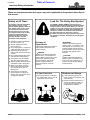
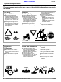
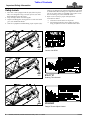
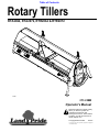
Table of Contents
Rotary Tillers
RTA2064, RTA2072, RTR2064 & RTR2072
25590
311-328M
Operator’s Manual
!
Read the Operator’s manual entirely.
When you see this symbol, the
subsequent instructions and
warnings are serious - follow without
exception. Your life and the lives of
others depend on it!
© Copyright 2007 Printed
7/03/07
Cover photo may show optional equipment not supplied
with standard unit.
Land Pride
Table of Contents
Table of Contents
Important Safety Information . . . . . . . . . . .1
Section 4: Maintenance and Lubrication 14
Safety at All Times . . . . . . . . . . . . . . . . . . . . . . . . . 1
Look For The Safety Alert Symbol . . . . . . . . . . . . . 1
Safety Labels . . . . . . . . . . . . . . . . . . . . . . . . . . . . . 4
Maintenance . . . . . . . . . . . . . . . . . . . . . . . . . . . . 14
Tine Replacement . . . . . . . . . . . . . . . . . . . . . . . . 14
Driveline Protection . . . . . . . . . . . . . . . . . . . . . . . 14
Clutches With 4 Adjusting Nuts . . . . . . . . . . . . . . 14
Clutch Run-In . . . . . . . . . . . . . . . . . . . . . . . . . 14
Clutch Disassembly & Assembly . . . . . . . . . . . 15
Clutches With 8 Hex Socket Bolts . . . . . . . . . . . . 16
Clutch Run-In . . . . . . . . . . . . . . . . . . . . . . . . . 16
Clutch Disassembly & Assembly . . . . . . . . . . . 16
Storage . . . . . . . . . . . . . . . . . . . . . . . . . . . . . . . . 17
Lubrication . . . . . . . . . . . . . . . . . . . . . . . . . . . . . . 18
Driveline U-Joint (Both Ends) . . . . . . . . . . . . . 18
Driveline Shaft . . . . . . . . . . . . . . . . . . . . . . . . . 18
Bearing on Right End of Rotor Shaft . . . . . . . . 18
Chaincase . . . . . . . . . . . . . . . . . . . . . . . . . . . . 19
Gearbox . . . . . . . . . . . . . . . . . . . . . . . . . . . . . 19
Introduction . . . . . . . . . . . . . . . . . . . . . . . .6
Application . . . . . . . . . . . . . . . . . . . . . . . . . . . . . . . 6
Using This Manual . . . . . . . . . . . . . . . . . . . . . . . . . 6
Owner Assistance . . . . . . . . . . . . . . . . . . . . . . . . . 6
Section 1: Assembly and Set-Up . . . . . . . .7
Tractor Requirements . . . . . . . . . . . . . . . . . . . . . . 7
3-Point Hitch & Shaft Cover Assembly . . . . . . . . . . 7
Driveline Guard Assembly . . . . . . . . . . . . . . . . . . . 7
Parking Stand Assembly . . . . . . . . . . . . . . . . . . . . 7
Tractor Hook-Up . . . . . . . . . . . . . . . . . . . . . . . . . . 9
Driveline Installation . . . . . . . . . . . . . . . . . . . . . . . . 9
Section 2: Operating . . . . . . . . . . . . . . . .11
Transporting . . . . . . . . . . . . . . . . . . . . . . . . . . . . 11
Parking . . . . . . . . . . . . . . . . . . . . . . . . . . . . . . . . 11
General Notes for Field Operations . . . . . . . . . . . 11
Operating Check List . . . . . . . . . . . . . . . . . . . . . . 11
Operating Instructions . . . . . . . . . . . . . . . . . . . . . 12
Section 3: Adjustments . . . . . . . . . . . . . .13
Drive Chain . . . . . . . . . . . . . . . . . . . . . . . . . . . . . 13
Skid Shoe . . . . . . . . . . . . . . . . . . . . . . . . . . . . . . 13
Rear Deflector & Down Pressure Kit . . . . . . . . . . 13
Section 5: Specifications & Capacities . .20
Section 6: Features & Benefits . . . . . . . .21
Section 7: Troubleshooting . . . . . . . . . . .22
Section 8: Appendix . . . . . . . . . . . . . . . . .23
Torque Values Chart . . . . . . . . . . . . . . . . . . . . . . 23
Notes . . . . . . . . . . . . . . . . . . . . . . . . . . . . . . . . . . 24
Warranty . . . . . . . . . . . . . . . . . . . . . . . . . . . . . . . 25
© Copyright 2007 All rights Reserved
Land Pride provides this publication “as is” without warranty of any kind, either expressed or implied. While every precaution has been taken in the preparation of this manual, Land
Pride assumes no responsibility for errors or omissions. Neither is any liability assumed for damages resulting from the use of the information contained herein. Land Pride reserves
the right to revise and improve its products as it sees fit. This publication describes the state of this product at the time of its publication, and may not reflect the product in the future.
Land Pride is a registered trademark.
All other brands and product names are trademarks or registered trademarks of their respective holders.
Printed in the United States of America.
RTA2064, RTA2072, RTR2064 & RTR2072 Rotary Tillers 311-328M
7/03/07
Land Pride
▲
Table of Contents
Important Safety Information
Important Safety Information
These are common practices that may or may not be applicable to the products described in
this manual.
Safety at All Times
Look For The Safety Alert Symbol
Thoroughly read and understand
the instructions given in this
manual before operation. Refer to
the “Safety Label” section, read
all instructions noted on them.
Do not allow anyone to operate
this equipment who has not fully
read and comprehended this
manual and who has not been
properly trained in the safe
operation of the equipment.
The SAFETY ALERT SYMBOL indicates there is a
potential hazard to personal safety involved and extra
safety precaution must be taken. When you see this
symbol, be alert and carefully read the message that
follows it. In addition to design and configuration of
equipment, hazard control and accident prevention
are dependent upon the awareness, concern,
prudence and proper training of personnel involved in
the operation, transport, maintenance and storage of
equipment.
▲ Operator should be familiar with
all functions of the unit.
▲ Operate implement from the
driver’s seat only.
▲ Do not leave tractor or implement
unattended with engine running.
▲ Dismounting from a moving
tractor could cause serious injury
or death.
▲ Do not stand between the tractor
and implement during hitching.
▲ Keep hands, feet, and clothing
away from power-driven parts.
▲ Wear snug fitting clothing to avoid
entanglement with moving parts.
▲ Watch out for wires, trees, etc.,
when raising implement. Make
sure all persons are clear of
working area.
▲ Turning tractor too tight may
cause implement to ride up on
wheels. This could result in injury
or equipment damage.
!
Be Aware of
Signal Words
A Signal word designates a degree or
level of hazard seriousness. The
signal words are:
! DANGER
Indicates an imminently hazardous
situation which, if not avoided, will
result in death or serious injury. This
signal word is limited to the most
extreme situations, typically for
machine components that, for
functional purposes, cannot be
guarded.
! WARNING
Indicates a potentially hazardous
situation which, if not avoided, could
result in death or serious injury, and
includes hazards that are exposed
when guards are removed. It may also
be used to alert against unsafe
practices.
! CAUTION
Indicates a potentially hazardous
situation which, if not avoided, may
result in minor or moderate injury. It
may also be used to alert against
unsafe practices.
For Your Protection
Shutdown and Storage
▲ Thoroughly read and understand
the “Safety Label” section, read all
instructions noted on them.
▲ Lower machine to ground, put
tractor in park, turn off engine, and
remove the key.
▲ Detach and store implements in a
area where children normally do
not play. Secure implement by
using blocks and supports.
OFF
REMO
VE
7/03/07
RTA2064, RTA2072, RTR2064 & RTR2072 Rotary Tillers 311-328M
1
Table of Contents
Land Pride
Important Safety Information
These are common practices that may or may not be applicable to the products described in
this manual.
Use Safety
Lights and Devices
Transport
Machinery Safely
▲ Slow moving tractors, selfpropelled equipment, and towed
implements can create a hazard
when driven on public roads. They
are difficult to see, especially at
night.
▲ Flashing warning lights and turn
signals are recommended
whenever driving on public roads.
Use lights and devices provided
with implement.
▲ Comply with state and local laws.
▲ Maximum transport speed for
implement is 20 mph. DO NOT
EXCEED. Never travel at a speed
which does not allow adequate
control of steering and stopping.
Some rough terrain require a
slower speed.
▲ Sudden braking can cause a
towed load to swerve and upset.
Keep Riders
Off Machinery
Practice Safe Maintenance
▲ Riders obstruct the operator’s
view, they could be struck by
foreign objects or thrown from the
machine.
▲ Never allow children to operate
equipment.
2
▲ Understand procedure before
doing work. Use proper tools and
equipment, refer to Operator’s
Manual for additional information.
▲ Work in a clean dry area.
▲ Lower the implement to the
ground, put tractor in park, turn off
engine, and remove key before
performing maintenance.
RTA2064, RTA2072, RTR2064 & RTR2072 Rotary Tillers 311-328M
Reduce speed if towed load is not
equipped with brakes.
▲ Use the following maximum
speed - tow load weight ratios as
a guideline:
20 mph when weight is less
than or equal to the weight of
tractor.
10 mph when weight is double
the weight of tractor.
▲ IMPORTANT: Do not tow a load
that is more than double the
weight of tractor.
▲ Allow implement to cool
completely.
▲ Do not grease or oil implement
while it is in operation.
▲ Inspect all parts. Make sure parts
are in good condition & installed
properly.
▲ Remove buildup of grease, oil or
debris.
▲ Remove all tools and unused
parts from implement before
operation.
7/03/07
Table of Contents
Land Pride
Important Safety Information
These are common practices that may or may not be applicable to the products described in
this manual.
Prepare for Emergencies
▲ Be prepared if a fire starts.
▲ Keep a first aid kit and fire
extinguisher handy.
▲ Keep emergency numbers for
doctor, ambulance, hospital and
fire department near phone.
Wear
Protective Equipment
Avoid High
Pressure Fluids Hazard
▲ Protective clothing and equipment
should be worn.
▲ Wear clothing and equipment
appropriate for the job. Avoid
loose fitting clothing.
▲ Prolonged exposure to loud noise
can cause hearing impairment or
hearing loss. Wear suitable
hearing protection such as
earmuffs or earplugs.
▲ Operating equipment safely
requires the full attention of the
operator. Avoid wearing radio
headphones while operating
machinery.
▲ Escaping fluid under pressure can
penetrate the skin causing serious
injury.
▲ Avoid the hazard by relieving
pressure before disconnecting
hydraulic lines.
▲ Use a piece of paper or
cardboard, NOT BODY PARTS, to
check for suspected leaks.
▲ Wear protective gloves and safety
glasses or goggles when working
with hydraulic systems.
▲ If an accident occurs, see a
doctor immediately. Any fluid
injected into the skin must be
treated within a few hours or
gangrene may result.
911
7/03/07
RTA2064, RTA2072, RTR2064 & RTR2072 Rotary Tillers 311-328M
3
Table of Contents
Land Pride
Important Safety Information
Safety Labels
1. Your tiller comes equipped with all safety labels in place.
They were designed to help you safely operate your tiller.
Read and follow these directions.
2. Keep all safety labels clean and legible.
3. Replace all damaged or missing labels. To order new labels
go to your Land Pride dealer.
4. Some new equipment installed during repair require safety
labels to be affixed to the replaced component as specified
by Land Pride. When ordering new components make sure
the correct safety labels are included in the request. To order new labels go to your Land Pride dealer.
5. Refer to this section for proper label placement.
To install new labels:
a. Clean the area the label is to be placed
b. Peel backing from label. Press firmly on surface
being careful not to cause air bubbles under label.
818-130C
25591
25591
Caution: 540 RPM
818-171C
Rotating Tines Hazard!
KEEP FRONT DEFLECTOR IN PLACE
25591
818-284C
Danger Thrown Object Hazard
4
RTA2064, RTA2072, RTR2064 & RTR2072 Rotary Tillers 311-328M
7/03/07
Land Pride
Table of Contents
Important Safety Information
818-142C
General Rotating Driveline
25591
818-858C
25591
General Safety Instructions
818-540C
Shield missing - Do Not operate.
22228
ROTATING DRIVELINE
KEEP AWAY!
818-552C
Rotating Driveline Hazard - Keep
Away!
22228
7/03/07
RTA2064, RTA2072, RTR2064 & RTR2072 Rotary Tillers 311-328M
5
Table of Contents
Land Pride
Introduction
Introduction
Land Pride welcomes you to the growing family of new
product owners.
This implement has been designed with care and built by
skilled workers using quality materials. Proper assembly,
maintenance, and safe operating practices will help you
get years of satisfactory use from the machine.
Application
The RTA20 & RTR20 Series Rotary Tillers are just right
for home gardening, landscape work, vegetable farming
or food plot maintenance. Available in three widths, the
20 Series Rotary Tiller turns up hard packed ground,
leaving a perfect seedbed for gardens to grass. Land
Pride’s RTA20 forward rotating tiller can work in all types
of ground conditions, with best results being obtained in
fairly mellow conditions. The RTR20 Series Rotary
Tillers feature a reverse tilling action for tougher ground
conditions. The reverse action “sucks” the tiller into the
ground, which prohibits the tiller from “walking” on hard
ground. The RTR20 Series Tiller also incorporates
spring loaded “sifting” rods behind the tines to help bury
large rocks and debris. The reverse action of the rotor
brings material up and over the top. Rocks and
vegetation cannot get through the sifting rods so they fall
first. Soil continues to get sifted before it falls, building a
layer of large to small dirt clods burying the rocks and
vegetation. Reverse tilling can reduce the number of trips
needed to turn the soil over. See “Features and
Benefits”, “Section 6” for additional information.
Owner Assistance
The Warranty Registration card should be filled out by
the dealer at the time of purchase. This information is
necessary to provide you with quality customer service.
If customer service or repair parts are required contact a
Land Pride dealer. A dealer has trained personnel, repair
parts and equipment needed to service the Rotary Tiller.
The parts on your Rotary Tiller have been specially
designed and should only be replaced with genuine Land
Pride parts. Therefore, should your Rotary Tiller require
replacement parts go to your Land Pride Dealer.
Serial Number Plate
For prompt service always use the serial number and
model number when ordering parts from your Land Pride
dealer. Be sure to include your serial and model numbers
in correspondence also. Refer to Figure 1 for the location
of your serial number plate.
Using This Manual
• This Operator’s Manual is designed to help familiarize
•
•
you with safety, assembly, operation, adjustments,
troubleshooting, and maintenance. Read this manual
and follow the recommendations to help ensure safe
and efficient operation.
The information contained within this manual was
current at the time of printing. Some parts may change
slightly to assure you of the best performance.
To order a new Operator’s or Parts Manual contact
your authorized dealer. Manuals can also be
downloaded, free-of-charge from our website at
www.landpride.com or printed from the Land Pride
Service & Support Center by your dealer.
Terminology
“Right” or “Left” as used in this manual is determined by
facing forward in the direction the machine will operate
while in use unless otherwise stated.
Definitions
NOTE: A special point of information that the
operator must be aware of before continuing.
IMPORTANT: A special point of information related
to its preceding topic. Land Pride’s intention is that
this information should be read and noted before
continuing.
6
RTA2064, RTA2072, RTR2064 & RTR2072 Rotary Tillers 311-328M
19363
Serial Number Plate Location
Figure 1
Further Assistance
Your dealer wants you to be satisfied with your new
Rotary Tiller. If for any reason you do not understand any
part of this manual or are not satisfied with the service
received, the following actions are suggested:
1. Discuss the matter with your dealership service
manager making sure he is aware of any problems
you may have and that he has had the opportunity to
assist you.
2. If you are still not satisfied, seek out the owner or
general manager of the dealership, explain the
problem and request assistance.
3. For further assistance write to:
Land Pride Service Department
1525 East North Street
P.O. Box 5060
Salina, Ks. 67402-5060
E-mail address
[email protected]
7/03/07
Land Pride
Table of Contents
Section 1: Assembly and Set-Up
Section 1: Assembly and Set-Up
Tractor Requirements
Driveline Guard Assembly
This tiller is designed with a 3-point category I hitch.
Horsepower rating of tractor should not exceed 40 PTO
horsepower.
1. Assemble clamp (#5) to the plate (#8) with one of the
wing bolts (#9).
2. Assemble the driveline guard (#6) to the top hitch
with the four other wing bolts (#9).
3. Install cover (#7) to tiller with wing bolts (#9).
4. Fasten plate (#8) to the driveline guard (#6) with the
5/16” bolt (#10), flat washer (#17), lockwasher (#16)
and nut (#13). The clamp (#5) should catch the lip of
cover (#7).
NOTE: In order to maintain steering control, ballast
may have to be added to your tractor. To determine
whether or not to add ballast, refer to your tractor
operator’s manual.
!
CAUTION
Do not over speed PTO or machine damage may result. This
tiller is designed to be used with a tractor using a 540 RPM
rear PTO.
3-Point Hitch & Shaft Cover Assembly
Parking Stand Assembly
Refer to Figure 1-1:
Install the parking stand (#2) through the stand bracket
and adjust stand to desired height and pin with 5/16” wire
lock pin (#20).
Refer to Figure 1-1:
1. Install right hand and left hand top hitch halves (#3)
and (#4) to the inside of the hitch mounting bars
bolted on the frame with 5/8” bolts (#11), nuts (#14)
and lock washers (#18). Do not tighten bolts at this
time.
2. Insert the top hitch spacer tube (#1) between the left
hand and right hand hitch as shown and secure with
the 3/4” bolt (#12), nut (#15) and lock washer (#19).
3. Tighten all bolts to recommended torques. See
“Torque Values Chart” on page 23.
7/03/07
RTA2064, RTA2072, RTR2064 & RTR2072 Rotary Tillers 311-328M
7
Table of Contents
Land Pride
Section 1: Assembly and Set-Up
20548
Hitch, Stand & Shaft Cover Assembly
Figure 1-1
8
RTA2064, RTA2072, RTR2064 & RTR2072 Rotary Tillers 311-328M
7/03/07
Table of Contents
Land Pride
Section 1: Assembly and Set-Up
Tractor Hook-Up
Implement End
Refer to Figure 1-2:
1. When using tractors with multi-speed PTO, be
certain PTO is set for 540 RPM.
2. Back tractor up to tiller until lower 3-Point links are
aligned with hitch clevises on tiller.
3. Secure the tractor’s 3-Point lower links to the lower
hitch clevises using 7/8” diameter hitch pins.
4. Secure the tractor’s top link to the tiller top hitch
using a 3/4” diameter hitch pin (supplied by
customer). Adjust tractor top link in order to level the
tiller.
5. Adjust the tractor’s 3-Point hitch lift height so that the
tiller tines are not lifted more than 14” off the ground
to prevent damage to the driveline u-joints.
Tractor End
Pull Collar Coupling
With
Slip Clutch Protection
22234
Push Pin Coupling
Figure 1-3
Implement End
Tractor End
Pull Collar Coupling
With
Slip Clutch Protection
19490
Tractor Hook-Up
Figure 1-2
Driveline Installation
22235
Pull Collar Coupling
Refer to Figure 1-3, Figure 1-4 & Figure 1-5:
The tiller driveline is coupled to the tractor and implement
shafts with either push pin couplers, pull collar couplers
or a combination of both and with either a shear bolt or
slip clutch on one end for protection from shock loads.
Always engage the PTO at low engine rpm to minimize
start-up torque on the driveline. Drivelines with friction
clutches must go through a “run-in” operation prior to
initial use and after long periods of inactivity. See
“Section 4: Maintenance and Lubrication” on page 14 for
a detailed description of maintaining the driveline.
!
Figure 1-4
Implement End
Tractor End
Push Pin Coupling
With
Shear Bolt Protection
CAUTION
Tractor PTO shield and all tiller guards must be in place at all
times during operation!
1. Slide driveline end with friction clutch or shear bolt
device over splined shaft of the gearbox and secure
with locking device of driveline.
2. Slide driveline over the tractor’s splined PTO shaft
and secure with locking device of driveline. Skip to
step 4 if driveline fits between tractor and implement.
7/03/07
Push Pin Coupling
22232
Figure 1-5
RTA2064, RTA2072, RTR2064 & RTR2072 Rotary Tillers 311-328M
9
Table of Contents
Land Pride
Section 1: Assembly and Set-Up
Refer to Figure 1-6:
3. The driveline will require shortening if it is too long to
fit between the tractor and tiller gearbox. Shorten
driveline as follows:
a. Set tractor in park, shut tractor engine off, set park
brake and remove switch key.
b. Pull driveline apart into two sections as shown in
Figure 1-6. Attach the outer driveline universal
joint to the tractor shaft and inner driveline
universal joint to the tiller gearbox shaft. Pull on
each driveline section to be sure the universal
joints are secured to the shafts.
c. Hold the driveline sections parallel to each other
to determine if they are too long. The inner and
outer shields on each section should end
approximately 1" short of reaching the universal
joint shield on the adjacent section (see “B”
dimension). If they are too long, measure 1" (“B”
dimension) back from the universal joint shield
and make a mark at this location on the inner and
outer driveline shields.
d. Cut off the inner shield at the mark (“X”
dimension). Cut the same amount off the inner
shaft (“X1” dimension). Repeat cut off procedure
(“Y” & “Y1” dimensions) to the outer driveline half.
e. Remove all burrs and cuttings.
f. Apply multi-purpose grease to the inside of the
outer shaft and reassemble the driveline.
g. Attach inner driveline yoke end to the tiller divider
gearbox input shaft.
h. Attach outer driveline yoke end to the tractor's
shaft.
4. Move the driveline back and forth to insure that both
ends are secured to the tractor and tiller shafts.
Reattach any end that is loose.
22227
Cutting the Driveline Shafts
Figure 1-6
IMPORTANT: Two small chains are supplied with
the driveline. These chains must be attached to the
driveline shields and to the rotary tiller and tractor to
restrict the shields from rotating.
5. Hook driveline safety chain at the tiller to the top hole
located in the front flange of the tiller hitch. Re-latch
safety chain to driveline guard.
6. Hook driveline safety chain at the tractor to the
tractor pull tongue. Re-latch safety chain to driveline
guard.
10
RTA2064, RTA2072, RTR2064 & RTR2072 Rotary Tillers 311-328M
7/03/07
Land Pride
Table of Contents
Section 2: Operating
Section 2: Operating
Transporting
IMPORTANT: Always disengage PTO before raising
the tiller to transport position.
!
CAUTION
When traveling on public roads whether at night or during the
day, use accessory light and devices for adequate warning to
operators of other vehicles. Comply with all federal, state and
local laws.
1. When raising the tiller to the transport position, be
sure that driveline does not contact tractor or tiller.
Adjust the tractor’s 3-point hitch lift height so that the
tiller tines are not lifted more than 14 inches off the
ground to prevent damage to the driveline.
2. Be sure to reduce tractor ground speed when
turning; and, leave enough clearance so the tiller
does not contact obstacles such as buildings, trees
or fences.
3. Select a safe ground travel speed when transporting
from one area to another. When traveling on
roadways, transport in such a way that faster moving
vehicles may pass you safely.
4. When traveling over rough or hilly terrain, shift tractor
to a lower gear.
Parking
The following steps should be taken when preparing to
store the tiller or unhitch it from the tractor. Also see
Storage in the “Maintenance and Lubrication” section
starting on page 17 for additional information on long
term storage of your tiller.
IMPORTANT: Turning or backing up with rotary
tines in the ground will damage the tiller.
17. Do not engage PTO with machine in the fully raised
or lowered position.
18. Periodically check for foreign objects wrapped
around the rotor shaft and remove them after
disengaging PTO, turning off tractor, and removing
ignition key.
Operating Check List
1. Park the tiller on a level, solid area.
2. Shut off tractor engine and engage parking brake.
3. Set parking stand to desired height for re-hook-up
and install pin to lock in place.
4. Unhitch from tractor.
5. See Storage in the “Maintenance and Lubrication”
section on page 17 if tiller is not going to be used for
a long period.
In addition to design and configuration of equipment,
hazard control and accident prevention are dependent
upon the awareness, concern, prudence and proper
training involved in its operation, transport, maintenance
and storage of equipment. Before beginning to operate
your Rotary Tiller, the following inspection should be
performed.
Operating Checklist
✔ Check
Read “Important Safety Information”
General Notes for Field Operations
Before beginning to till the following inspection should be
performed:
1. Check oil level in gearbox and chaincase. Refer to
Lubrication in the “Maintenance and Lubrication”
section starting on page 14.
2. Check that all plugs have been replaced properly in
the gearbox and chaincase.
3. Check drive chain tension. Refer to Drive Chain in
the “Adjustment” section on page 13.
4. Be sure all tiller tines, bolts and nuts are tight.
5. Be certain all guards and shields are in place and
secure.
7/03/07
6. Grease driveline shaft and all other grease fittings.
7. Clear the area to be tilled of rocks, branches and
other foreign objects.
8. Tall grass and weeds may need to be mowed before
tilling.
9. Operate with 540 rpm PTO tractor.
10. At first begin tilling at a slow forward speed and shift
up as ground conditions warrant.
11. Tiller should be operated with the tiller deck level to
the ground.
12. Tiller tines will cut better at a faster rotor speed than
at reduced throttle.
13. Do not engage PTO at full throttle.
14. Tilling should not be done in wet conditions as soil
will stick to tines.
15. After tilling the first 50 feet, stop and check to see that
the tiller is adjusted properly.
16. Do not make turns or attempt to back up while tiller is
in the ground. See important note below.
Reference
Page 1
Read all of the Tractor Hook-Up and preparation
instructions.
Page 9
Read “Operating Instructions”
Page 11
Lubricate the tiller as needed. Refer to Lubrication.
Page 18
Check the tiller initially and periodically for loose
bolts & pins, Torque Values Chart.
Page 23
Make sure all guards and shields are in place.
Page 11
Check initially and periodically for loose bolts, pins,
and chains.
Page 11
RTA2064, RTA2072, RTR2064 & RTR2072 Rotary Tillers 311-328M
11
Table of Contents
Land Pride
Section 2: Operating
Operating Instructions
Before using your Land Pride RTA20 Series Rotary
Tiller, you should have completely read the Operator’s
Manual, properly attached the Tiller to the tractor, cut the
Drive-line to proper length, Run-in the clutch, and gone
through the Operating Checklist. If you have missed any
of these steps, please complete them before proceeding.
Now that you have properly prepared yourself and your
tiller, it’s time to do some tilling. Carefully drive the tractor
to the site where you intend to till. You should have
already cleaned this site of any large limbs, rocks, trash,
metal or extraneous debris. Best results will be achieved
if you have mounted your tiller offset to the left far enough
to cover the tread of your left tractor wheel. Line the
tractor up just to the right of center on your tillage plot.
You will be working from the center out and always
turning to the left to line up for your next pass. Lower the
tiller half way to the ground and reduce your tractor
engine speed to about one quarter throttle. Engage the
PTO and gradually increase the engine speed until you
reach full PTO speed of 540 rpm. Lower the Tiller to the
ground and simultaneously commence forward travel of
approximately 2 mph. Do not make turns or attempt to
back up while tiller is in the ground. See important note
below.
IMPORTANT: Turning or backing up with rotary
tines in the ground will damage the tiller.
Travel about 50ft. and then stop to check your results.
When stopping, remember to lift the tiller out of the
ground, stop the tractor, reduce engine speed,
disengage the PTO, set the park brake, shut off the
tractor, and remove the keys. If you are tilling too shallow
or too deep, adjust the skid shoes accordingly. If the soil
texture is too coarse, lower the leveling door and reduce
your ground speed. If the soil texture is too fine, you will
need to raise your leveling door and increase your
ground speed. For any other problem conditions that
may arise, you will want to refer to the Troubleshooting
section of this Operator’s Manual.
When you are done tilling for the day, make sure you use
proper tractor shut down procedures before you get off of
the tractor. If you are detaching your tiller, make sure you
park it on a dry and level surface leaving it clean and
ready for the next use. When you put your tiller up for the
season, make sure you refer to the Storage Directions in
this Operator’s Manual.
With a little practice and a few adjustments, you will soon
be achieving the results you want with your Land Pride
Rotary Tiller. See “Features and Benefits” page 21 or
“Specifications and Capacities” page 20 for additional
information and performance enhancing options.
12
RTA2064, RTA2072, RTR2064 & RTR2072 Rotary Tillers 311-328M
7/03/07
Table of Contents
Land Pride
Section 3: Adjustments
Section 3: Adjustments
Drive Chain
Refer to Figure 3-1:
The tension on the drive chain can be easily adjusted by
using the chain tightener stud.
Should excessive backlash occur, unscrew the lock nut,
turn the bolt, Figure 3-1, clockwise as indicated by the
arrow, until idler arm is firm against chain, then back the
bolt off counterclockwise 1/4” turn. Re-lock the lock nut
while holding the head of the bolt in place. Refer to the
Torque Values Chart in the “Appendix” section on
page 23.
Rear Deflector
& Down Pressure Kit
The rear deflector can be adjusted closer to the ground to
produce a fine soil texture or can be raised to produce a
coarse soil texture by adjusting the spring rods. Adjust
rear deflector to the desired height and install cotter pins
in one of the top six holes on the spring rods above the
cushion springs Figure 3-3.
25590
20549
Chain Tightener
Figure 3-1
Rear Deflector
Figure 3-3
Refer to Figure 3-2
The skid shoes can be raised or lowered for the desired
tilling depth by:
The rear deflector can be raised and secured for
replacement of spring tines by removing the cotter pins
and raising the deflector enough to reinstall the cotter
pins in hole no. 7 on the spring rods below the cushion
springs.
Skid Shoe
1.
2.
3.
4.
5.
Raise tiller off the ground and properly support.
Loosen pivot bolt on front of shoe.
Remove adjusting bolt on rear of shoe.
Adjust skid shoe to desired location.
Install adjusting bolt, and tighten both the adjusting
bolt and the pivot bolt.
An optional spring kit, part no. 311-162A, is offered to
allow you to apply pressure down on the rear deflector for
leveling. Adjust locking collars up to compress springs to
desired pressure.
NOTE: Too much pressure will cause premature
wear on the rear deflector.
IMPORTANT: Be sure both skid shoes are adjusted
the same.
Loosen
20550
Skid Shoe Adjustment
Figure 3-2
7/03/07
RTA2064, RTA2072, RTR2064 & RTR2072 Rotary Tillers 311-328M
13
Table of Contents
Land Pride
Section 4: Maintenance and Lubrication
Section 4: Maintenance and Lubrication
Maintenance
!
Driveline Protection
CAUTION
For safety reasons, each maintenance operation must be
performed with the tractor’s PTO disengaged, the Tiller
lowered completely to the ground or on safely supported
blocking, tractor engine shut off and ignition key removed.
Proper servicing and adjustment can increase the life of
any implement. With careful and systematic inspection,
you can avoid costly maintenance, time and repair.
After using your tiller for several hours, check all bolts to
be sure they are tight.
Replace any worn, damaged or illegible safety labels by
obtaining new labels form your Land Pride Dealer.
Driveline components are protected from shock loads by
a friction slip clutch. The clutch must be capable of
slippage during operation to protect the gearbox,
driveline and other drive train parts.
Friction clutches should be “run-in” prior to initial
operation and after long periods of inactivity to remove
any oxidation that may have accumulated on the friction
surfaces. Repeat “run-in” instructions at the beginning of
each season and when moisture and/or condensation
seizes the inner friction plates.
Refer to Figure 4-2 below and Figure 4-3 on page 16 to
determine which friction clutch your Rotary Tiller has.
Follow run-In, disassembly and assembly instructions for
your specific clutch.
Clutches With 4 Adjusting Nuts
Clutch Run-In
RTA20
Rotation
Refer to Figure 4-2 (View - A):
1. Using a pencil or other marker, scribe a line across the
exposed edges of the clutch plates and friction disks.
2. Tighten all 4 nuts uniformly until spring load is low
enough that the clutch slips freely with PTO engaged.
23696
Di
rec
tio
no
fT
rav
el
RTR20
Rotation
20551
Tine Replacement
Figure 4-1
Tine Replacement
Refer to Figure 4-1:
!
WARNING
Worn tines may be very sharp!
IMPORTANT: Always install tine with cutting edge
facing direction of rotor shaft rotation. When
ordering replacement tines, be sure to order both
right and left hand tines.
1. Remove 2 bolts and nuts from tine to be replaced.
Remove tine.
2. Install new tine on side of attaching flange.
3. Replace 2 bolts and nuts and tighten nuts to proper
torque. See the Torque Values Chart in the
“Appendix” section on page 23.
IMPORTANT: Replace tines with genuine Land
Pride tines only.
14
RTA2064, RTA2072, RTR2064 & RTR2072 Rotary Tillers 311-328M
Clutches With 4 Adjusting Nuts
Figure 4-2
3. Start tractor and engage PTO for 2-3 seconds to
permit slippage of clutch surfaces. Disengage PTO,
then re-engage a second time for 2-3 seconds.
Disengage PTO, shut off tractor and remove key. Wait
for all components to stop before dismounting from
tractor.
4. Inspect clutch and ensure that the scribed markings
made on the clutch plates have changed position.
Slippage has not occurred if any two marks on the
friction disk and plate are still aligned. A clutch that
has not slipped must be disassembled to separate
the friction disk plates. See Clutch Disassembly &
Assembly on page 15.
Refer to Figure 4-2 (View - B):
5. Turn all 4 nuts fully back if no two marks on the friction
disk and plate are still aligned. Clutch is ready for use.
6. The clutch should be checked during first hour of
cutting and periodically each week. An additional set
of scribe marks can be added to check for slippage.
7/03/07
Table of Contents
Land Pride
Section 4: Maintenance and Lubrication
Clutch Disassembly & Assembly
If clutch run-in procedure indicates that one or more of the
friction disks did not slip, then the clutch must be
disassembled to separate the friction disks.
Assembly
NOTE: Before proceeding, secure clutch firmly in a
vise or other clamping device to prevent injury.
Step 1
Place the hub and friction disks into the
housing.
Disassembly
Step 1
Remove snap ring.
Step 2
Step 2
Compress the Belleville Springs to the
pressure plate by tightening the four hex
nuts and then placing the assembly into the
clutch housing.
Remove backup ring, lock collar,
compression spring, bottom backup ring,
and balls.
Step 3
Tighten the four hex nuts uniformly until the
clutch pack and hub are loose.
Step 3
Bend the retaining lugs inward over the
Belleville Spring edges to secure the spring
before backing the four hex nuts off.
Step 4
Step 4
Bend all four retaining lugs out on the edge
of the clutch housing.
With the lugs bent in, loosen the four hex
nuts completely to the end of the threaded
studs.
Step 5
Step 5
Insert greased balls.
Remove the thrust plate with the Belleville
Springs and lug rings to access friction
disks and hub for inspection or service.
Step 6
Install bottom backup ring, compression
spring, lock collar, and top backup ring.
Step 6
Inspect friction disks and hub.
14232
7/03/07
Step 7
Install snap ring.
14233
RTA2064, RTA2072, RTR2064 & RTR2072 Rotary Tillers 311-328M
15
Table of Contents
Land Pride
Section 4: Maintenance and Lubrication
Clutches With 8 Hex Socket Bolts
Clutch Run-In
Refer to Figure 4-3:
1. Loosen counterclockwise all 8 hex head socket bolts
uniformly 6 full turns.
2. Cycle clutch on and off 5 or 6 times (15 seconds on
and 15 seconds off) with the engine operating at half
throttle. Disengage driveline, shut off tractor and
remove key. Wait for all components to stop before
dismounting from tractor.
3. Tighten hex head socket bolts fully back. Clutch is
ready for use
4. The clutch should be checked during the first hour of
cutting and periodically each week.
(IMPORTANT NOTICE)
Check position of lip on stop
flange (UP or DOWN).
Replace stop flange with lip in
its original position.
Hex Head
Socket Bolts
21270
Clutch Run-In With 8- Hex Head Socket Bolts
Figure 4-3
Clutch Disassembly & Assembly
Refer to Figure 4-4:
If clutch run-in procedure above indicated that one or more
friction disks did not slip, then the clutch must be
disassembled into separate friction disks.
1. Rotate 8 Alan head socket bolts (#2) all the way out
to free stop flange (#3).
2. Record position of the lips (up or down) on stop
flange (#3) and then rotate flange and remove it.
3. Remove the following inner components:
a. Spring kit (#4)
b. Pressure flange (#5)
c. 1st Friction Disc (#6)
d. Hub with flange and pull collar (#7 & #1)
e. 2nd Friction disc (#6)
f. Intermediary flange (#8)
g. 3rd Friction disc (#6)
h. Hub disc (#9)
i. 4th Friction disc (#6)
j. Bearing (#10)
4. Inspect all components and replace to their original
position. Make certain stop flange (#3) is replaced
with its flanges down as shown.
5. Fully tighten all 8 Alan head socket bolts (#2).
16
RTA2064, RTA2072, RTR2064 & RTR2072 Rotary Tillers 311-328M
21303
Clutch Assembly
Figure 4-4
7/03/07
Land Pride
Table of Contents
Section 4: Maintenance and Lubrication
Storage
At the end of the working season or when the tiller will not
be used for a long period, it is good practice to clean off
any dirt or grease that may have accumulated on any of
the moving parts.
Check the tines for wear and replace if necessary. See
Tine Replacement earlier in this section.
Inspect the tiller for loose, damaged or worn parts and
adjust or replace if needed.
Lubricate as noted in Lubrication starting on page 18.
Repaint parts where paint is worn or scratched to prevent
rust.
Drain gearbox and chaincase oil. Drain oil in gearbox by
removing the bottom drain plug or right hand cap. Drain
oil in chaincase by removing the bottom plug and tipping
tiller backwards. Be sure to refill gearbox and chaincase
at this time.
Store tiller in a clean, dry place.
7/03/07
RTA2064, RTA2072, RTR2064 & RTR2072 Rotary Tillers 311-328M
17
Table of Contents
Land Pride
Section 4: Maintenance and Lubrication
Lubrication
Lubrication
Legend
Multi-purpose
spray lube
Multi-purpose
grease lube
Multi-purpose
oil lube
20
Intervals in hours at which
lubrication is required.
8
Hours
Driveline U-Joint (Both Ends)
Coat PTO u-joint with grease every 8 hours of operation.
22230
Type of grease = Multi-Purpose
Quantity = Coat Generously
20
Hours
Driveline Shaft
Disconnect Driveline from the tractor and slide apart.
Clean and coat the inner tube of the Driveline shaft with a
light film of grease and then reassemble.
Type of grease = Multi-Purpose
22229
Quantity = Coat Generously
8
Hours
Bearing on Right End of Rotor Shaft
Grease bearing on right end of rotor shaft until grease
starts to purge from the relief hole in the bearing mount
casting on the inside of the tiller end plate.
Type of grease = Multi-Purpose
20550
18
Quantity = Coat Generously
RTA2064, RTA2072, RTR2064 & RTR2072 Rotary Tillers 311-328M
7/03/07
Land Pride
Table of Contents
Section 4: Maintenance and Lubrication
As
Required
Fill Plug
Chaincase
Drain Plug
With tiller on level ground, check oil level in chaincase
by removing lower plug. Oil should reach the plug hole.
Fill if necessary with Shell Alvania EP00 oil and
retighten plug. Tiller should be level when checking.
Type = Recommended: Shell Alvania EP00 Oil
Alternate: SAE 90 wt. oil
25592
Quantity = As required
As
Required
Do Not
Overfill!
Gearbox
Check the oil level in the gearbox by removing the plug
located in the center of rear cover. Fill if necessary with
SAE 90 oil and retighten both plugs.
20552
IMPORTANT: Should your gearbox require repair,
take it to your Land Pride Dealer! Check the oil level
in the gearbox at least every 50 hours of operation.
Type of lubrication = SAE 80-90W EP Oil
Quantity = As required
7/03/07
RTA2064, RTA2072, RTR2064 & RTR2072 Rotary Tillers 311-328M
19
Table of Contents
Land Pride
Section 5: Specifications & Capacities
Section 5: Specifications & Capacities
RTA20 & RTR20 Series
Model
Weight
Tilling Width
Overall Width
Offset Capabilities
Number of Flanges
Number of Tines per Flange
PTO Driveline
RTA2064
RTR2064
RTA2072
689 lbs.
748 lbs.
734 lbs.
64”
70 1/4”
14”
8
Gearbox
Gearbox Lubrication
Drive Chain
Drive chain lubricant
Sprockets
Rotor Swing Diameter
Rotor Shaft Speed
20
RTA2064, RTA2072, RTR2064 & RTR2072 Rotary Tillers 311-328M
RTR2072
795 lbs.
72”
77 5/16"
18”
9
6
ASAE Category III Heavy Duty
Friction Clutch or Shear Bolt
40 HP Input at 540 rpm 1.92:1 Ratio
Cast Iron Housing, Straight Bevel Gears
SAE80-90W EP oil
#80 roller chain in flowable grease bath
Shell Alvania EP 00 or equivalent
Splined Bores
17"
220 rpm at 540 rpm PTO
7/03/07
Table of Contents
Land Pride
Section 6: Features & Benefits
Section 6: Features & Benefits
RTA20 & RTR20 Series
Features
Benefits
20 Series
Fills the gap between our 15 and 25 Series Tillers, both in size and price.
Tractor HP
23 - 40 HP.
Gearbox Warranty
3 Years on housing, gears, shafts & seals. Shows our confidence in the product.
Working Widths
64” & 72” Meets a wide range of customer needs.
Formed Deck
Handles material more efficiently, sheds water.
Integral Hitch
Upper hitch, gearbox and gearbox mount brought together to form a stronger overall hitch
frame.
Clevis Style Lower Hitch
Allows easier hook-up of lower 3-point arms.
Cat. 1 Hitch fits Land Pride
Quick-Hitch
Allows for quick and easy one-person hook-up. Offset is not comparable with Quick-Hitch.
RTR Reverse rotation model
or RTA forward rotation model
Land Pride has the market on reverse rotation. This brings in a quality tiller at a more
affordable price for landscapers. We offer forward rotation for contractors who want it.
Reverse tilling action
Reverse action ‘sucks’ tiller into ground, does not walk on top of hard ground like forward
rotation tillers can.
Sideshift capability
Sideshifts by loosening 6 U-bolts and sliding hitch points and gearbox over. Allows
covering right tire track.
Parking Stand
Allows for easy hook-up and storage
Six tines standard on RTR20
Four tines standard on RTA20
with six being optional
Six tines cut through the ground smoother.
C Tines
C Tines take less horsepower to move through the ground.
17” Rotor swing diameter
For deep tilling action.
Double lip seal on rotor
bearing
Double lip seal keeps the dirt out and the grease in.
#80 Drive chain enclosed in
oil bath
Heavy-duty drive chain reduces stretching. Oil keeps constant lubrication and holds wear
to a minimum.
Easy to adjust chain tightener
Cast iron chain tightener is a simple bolt adjustment to keep constant tension on the chain.
Stamped chain cover
Stamped forming adds additional strength.
Adjustable skid shoes
Control depth from various settings.
Cat. 3 driveline with slipclutch (option)
Heavy driveline for rough conditions. Slip-clutch protects other drive train components.
Material separator behind
tilling action (RTR only)
3/8” Rods sift the material letting bigger items fall first. Sifted soil falls last burying the
bigger items. Attachment is one all welded piece for easy assembly.
Formed rear deflector with
springs
Formed steel gives the rear deflector additional strength. Springs allow deflector to
bounce as it hits obstructions.
7/03/07
RTA2064, RTA2072, RTR2064 & RTR2072 Rotary Tillers 311-328M
21
Table of Contents
Land Pride
Section 7: Troubleshooting
Section 7: Troubleshooting
Problem
Machine makes intermittent
clicking noise
Driveline vibrates
Gearbox noise is noticeable and constant
Oil leaking from gearbox
Rotor will not turn
Tillage depth insufficient
Soil texture too coarse
Soil texture too fine
Machine skips or leaves
crop residue
Tines balling up with soil
Tiller bumping on ground
22
Cause
Solution
Loose tines
Tighten tines
Gearbox tooth damaged
Replace damaged gear
Chain damaged
Replace damaged chain link
Worn universal joint
Replace universal joint
Excessive trash wrapped on rotor
Remove trash
Machine lifted too high
Lower machine and readjust tractor lift stop
May be normal on new machine
Allow time for break-in
Low oil level
Add oil
Worn gears
Replace gears
Damaged seals or gaskets
Replace seals or gaskets
Gearbox overfilled
Drain to proper level
PTO not engaged
Engage PTO
Broken drive chain
Repair drive chain
Shearbolt broken on driveline
Replace shearbolt
Friction clutch slipping
Reduce load to tiller
Tiller carried by tractor
Lower tractor 3-point arms
Insufficient power
Increase tractor rpm
Skid Shoes need adjusting
Adjust skid shoes
Worn or bent tines
Replace tines
Tines incorrectly installed
Check tine placement
Obstacles entangled in tines and/or rotor
Clear rotor and/or tines
Lower hitch clevises on tiller in wrong position
Relocate lower hitch clevises
Leveling door too high
Lower leveling door
PTO speed too slow
Increase PTO speed
Ground speed too fast
Decrease ground speed
Leveling door too low
Raise leveling door
Ground speed too slow
Increase Ground Speed
Badly worn tines
Replace worn tines
Friction clutch slipping
Reduce load
Ground speed too fast for conditions
Reduce ground speed
Worn or bent tines
Replace tines
Tines incorrectly installed
Install tines correctly
Rear deflector too low
Raise rear deflector
Tractor speed too fast
Decrease tractor speed
Soil too wet
Wait until soil dries
Obstacles entangled in tines and/or rotor
Clear rotor and/or tines
Tines not installed correctly
Install tines correctly
RTA2064, RTA2072, RTR2064 & RTR2072 Rotary Tillers 311-328M
7/03/07
Table of Contents
Land Pride
Section 8: Appendix
Section 8: Appendix
Torque Values Chart
Bolt Head Identification
Bolt Size
(Inches)
in-tpi 1
1/4" - 20
1/4" - 28
5/16" - 18
5/16" - 24
3/8" - 16
3/8" - 24
7/16" - 14
7/16" - 20
1/2" - 13
1/2" - 20
9/16" - 12
9/16" - 18
5/8" - 11
5/8" - 18
3/4" - 10
3/4" - 16
7/8" - 9
7/8" - 14
1" - 8
1" - 12
1-1/8" - 7
1 1/8" - 12
1 1/4" - 7
1 1/4" - 12
1 3/8" - 6
1 3/8" - 12
Grade 2
Grade 5
N · m ft-lb 3 N · m
7.4
8.5
15
17
27
31
43
49
66
75
95
105
130
150
235
260
225
250
340
370
480
540
680
750
890
1010
5.6
6
11
13
20
22
32
36
49
55
70
79
97
110
170
190
165
185
250
275
355
395
500
555
655
745
11
13
24
26
42
47
67
75
105
115
150
165
205
230
360
405
585
640
875
955
1080
1210
1520
1680
1990
2270
ft-lb
8
10
17
19
31
35
49
55
76
85
110
120
150
170
265
295
430
475
645
705
795
890
1120
1240
1470
1670
Bolt Head Identification
Bolt Size
(Metric)
Grade 8
N·m
16
18
33
37
59
67
95
105
145
165
210
235
285
325
510
570
820
905
1230
1350
1750
1960
2460
2730
3230
3680
ft-lb
12
14
25
27
44
49
70
78
105
120
155
170
210
240
375
420
605
670
910
995
1290
1440
1820
2010
2380
2710
8.8
5.8
Class 5.8
mm x pitch N · m
ft-lb
10.9
Class 8.8
N·m
ft-lb
Class 10.9
N·m
ft-lb
M 5 X 0.8
4
3
6
5
9
7
M6X1
7
5
11
8
15
11
M 8 X 1.25 17
12
26
19
36
27
M8X1
18
13
28
21
39
29
M10 X 1.5
33
24
52
39
72
53
M10 X 0.75 39
29
61
45
85
62
M12 X 1.75 58
42
91
67
125
93
M12 X 1.5
60
44
95
70
130
97
M12 X 1
90
66
105
77
145
105
M14 X 2
92
68
145
105
200
150
M14 X 1.5
99
73
155
115
l215
160
M16 X 2
145
105
225
165
315
230
M16 X 1.5
155
115
240
180
335
245
M18 X 2.5
195
145
310
230
405
300
M18 X 1.5
220
165
350
260
485
355
M20 X 2.5
280
205
440
325
610
450
M20 X 1.5
310
230
650
480
900
665
M24 X 3
480
355
760
560
1050 780
M24 X 2
525
390
830
610
1150 845
M30 X 3.5
960
705
1510 1120 2100 1550
M30 X 2
1060 785
1680 1240 2320 1710
M36 X 3.5
1730 1270 2650 1950 3660 2700
M36 X 2
1880 1380 2960 2190 4100 3220
1 in-tpi = nominal thread diameter in inches-threads per in.
2 N· m = newton-meters
3 ft-lb= foot pounds
4 mm x pitch = nominal thread diameter in millimeters x thread
1 1/2" - 6
1180 870
2640 1950 4290 3160
pitch
1 1/2" - 12
1330 980
2970 2190 4820 3560
Torque tolerance + 0%, -15% of torquing values. Unless otherwise specified use torque values listed above.
7/03/07
RTA2064, RTA2072, RTR2064 & RTR2072 Rotary Tillers 311-328M
23
Table of Contents
Land Pride
Section 8: Appendix
Notes
24
RTA2064, RTA2072, RTR2064 & RTR2072 Rotary Tillers 311-328M
7/03/07
Table of Contents
Land Pride
Section 8: Appendix
Warranty
Land Pride warrants to the original purchaser that this Land Pride product will
be free from defects in material and workmanship beginning on the date of
purchase by the end user according to the following schedule when used as
intended and under normal service and conditions for personal use.
Overall Unit and Driveline: One year Parts and Labor
Gearbox: 5 years Parts and Labor
Tines and Driveline Friction Discs: Considered wear items
This Warranty is limited to the replacement of any defective part by Land
Pride and the installation by the dealer of any such replacement part, and does
not cover common wear items such as blades, belts, tines, etc. Land Pride
reserves the right to inspect any equipment or parts which are claimed to have
been defective in
material or workmanship.
This Warranty does not apply to any part or product which in Land Pride’s
judgment shall have been misused or damaged by accident or lack of normal
maintenance or care, or which has been repaired or altered in a way which
adversely affects its performance or reliability, or which has been used for a
purpose for which the product is not designed. Misuse also specifically includes
failure to properly maintain oil levels, grease points, and driveline shafts.
Claims under this Warranty must be made to the dealer which originally sold
the product and all warranty adjustments must be made through such dealer.
Land Pride reserves the right to make changes in materials or design of the
product at any time without notice.
This Warranty shall not be interpreted to render Land Pride liable for damages
of any kind, direct, consequential, or contingent to property. Furthermore, Land
Pride shall not be liable for damages resulting from any cause beyond its
reasonable control. This Warranty does not extend to loss of crops, any expense
or loss for labor, supplies, rental machinery or for any other reason.
No other warranty of any kind whatsoever, express or implied, is made
with respect to this sale; and all implied warranties of merchantability and
fitness for a particular purpose which exceed the obligations set forth in
this written warranty are hereby disclaimed and excluded from this sale.
This Warranty is not valid unless registered with Land Pride within 30 days
from the date of purchase by the end user.
7/03/07
RTA2064, RTA2072, RTR2064 & RTR2072 Rotary Tillers 311-328M
25
Corporate Office: P.O. Box 5060
Salina, Kansas 67402-5060 USA
www.landpride.com