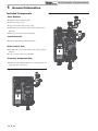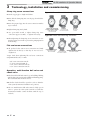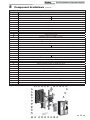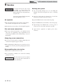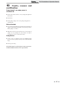
1
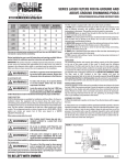
SL-PS-I-O Rev B Solar Pump Station Installation and Operation Manual SPS0250, SPS0500 & SPS1000 WARNING: This manual must only be used by a qualified heating installer/ service technician. Read all instructions, before installing. Perform steps in the order given. Failure to comply could result in severe personal injury, death, or substantial property damage. Save this manual for future reference. Contents HAZARD DEFINITIONS .................................................... 2 1. GENERAL INFORMATION Included components ..................................................... 3-4 2. INSTALLING THE SOLAR STATION Installing the solar station on a wall ................................... 5 Installing the relief valve ..................................................... 5 Installation, wall bracket for expansion tank ...................... 5 Installation, connection lines to tank and collector............ 5 Piping .......................................................................... 5 Clamp ring screw connections ................................... 5 3. TECHNOLOGY, INSTALLATION AND COMMISSIONING Clamp ring screw connections .......................................... 6 Operation, multi-function ball valve and check valve .......... 6 4. COMMISSIONING THE SOLAR SYSTEM General.............................................................................. 7 Flat seal screw connections .............................................. 7 Filling, flushing and bleeding ............................................. 7 5. PRESSURE LOSS AND RESIDUAL DELIVERY HEIGHT ..................................................... 8 6. VFS FLOW SENSOR .................................................. 9 7. TECHNICAL DATA FOR SOLAR STATION ........ 10-11 8. COMPONENT BREAKDOWN SPS0250 ......................................................................... 12 SPS0500 ........................................................................... 12 SPS1000 ........................................................................... 13 9. SERVICE Air separator .................................................................... 14 Flat seal screw connections ............................................ 14 Clamp ring screw connections ........................................ 14 Disassembling the solar station ........................................ 14 Draining the system .......................................................... 14 10. FAULTS, CAUSES AND RECTIFICATIONS Pump doesn’t run when power is switched on ................. 15 Motor blocked .................................................................... 15 Pump noise ....................................................................... 15 Revision Notes ................................................. Back Cover Hazard definitions The following defined terms are used throughout this manual to bring attention to the presence of hazards of various risk levels or to important information concerning the life of the product. DANGER DANGER indicates an imminently hazardous situation which, if not avoided, will result in death or serious injury. WARNING indicates a potentially hazardous situation which, if not avoided, could result in death or serious WARNING injury. CAUTION indicates a potentially hazardous situation which, if not avoided, may result in minor or moderate CAUTION injury. CAUTION CAUTION used without the safety alert symbol indicates a potentially hazardous situation which, if not avoided, may result in property damage. NOTICE NOTICE indicates special instructions on installation, operation, or maintenance that are important but not related to personal injury or property damage. 2 SL-PS Installation & Operation Manual 1 General Information WARNING Before starting work, the Installer must read, understand and note these installation and operating instructions. WARNING The solar pump station may only be installed and maintained by trained professionals. Trainees may only work on the product under the supervision of an experienced person. WARNING All instructions in this Installation & Operation manual should be observed when using the solar station. No other form of use is intended.The manufacturer is not liable for any damage resulting from misuse of the solar station. For safety reasons, modifications or changes are not permitted. WARNING ■ The solar station must be installed as far away from the collectors as possible. Extremely high temperatures may occur in the pipes near the collectors. If installing in attic space, ensure that the instruments do not overheat. ■ The pressure / temperature operating parameters must be within the prescribed limits. Excess operating temperatures should be avoided for continuous operation. ■ The provisions stated in DIN EN 12976-1 should be observed when installing solar systems. ■ The expansion tank should be regularly checked according to DIN 4807. ■ Solar systems should be grounded to protect against lightning. ■ The system’s electrical connection for sensors and voltage supply should only be established by a trained professional. The relevant specifications (VDE 0100, VDE 0185, VDE 0190 etc.) should be observed as well as special local (construction) requirements. (Grey cable = tank, black cable = collector) ■ The solar pump station’s componentry varies depending on type and equipment. ■ The diagrams used are examples. ■ Subject to technical changes and further developments. WARNING A properly sized expansion tank must be used to avoid damage to the solar thermal system. WARNING Thermal expansion tanks should be sized to account for 1.5 times the solar system circuit volume. WARNING The expansion tank may be hot, ensure that scalding does not occur. WARNING Failure to heed these instructions, especially the safety instructions, can result in the destruction of and defects on the expansion tank, endanger persons, and impair the operation. 3 SL-PS Installation & Operation Manual 1 General Information Included Components Solar Station: ■ Grundfos solar circulation pump ■ VFS sensor (flow sensor) ■ 145 psi relief valve, with pressure gauge ■ Multi-function instruments (Flow Check, Thermometer, Fill Valve) ■ EPP two-part bracket with mounting kit Installation kit: ■ Wall and tank bracket with mounting kit Solar Control unit: ■ LCD Plus solar control unit with integrated energy balance function. ■ 2 collector and 2 tank sensors Pt 1000 Technical documentation: ■ Operation and installation instructions (with appendix) for pump and solar control unit. Figure 1-1 SPS0250/ SPS0500 4 Figure 1-2 SPS1000 SL-PS Installation & Operation Manual 2 Installing the solar station Installing the solar station on a wall ■ Remove front insulation shell. ■ The solar pump station forms a single unit with the wall bracket and rear insulation shell. Secure both components as a complete unit at the intended location, working the front and using anchors and screws suitable for the wall construction type. Installing the relief valve ■ The solar station is equipped with a solar safety relief valve which meets the relevant requirements. ■ Fit the enclosed relief valve to the outlet of the return instruments above the pump using the 3/4" union nuts. A gasket is enclosed with the solar station for use when installing the relief valve. ■ The enclosed discharge connection bracket should be fitted to the safety valve so that there is no risk of scalding should liquid escape. Follow local codes for drainage piping. Installation, wall bracket for expansion tank: (Lochinvar/TiSUN accessories) ■ Fit the wall bracket for the expansion tank (if equipped) to the right of the solar station. ■ Ensure that the corrugated stainless steel hose is long enough for the connection between the pump station and the expansion tank, not forgetting the expansion coupling. Installation, connection lines to tank and collector A) Piping ■ Connect the lines between the solar pump station and tank. ■ Connect supply and return lines to the collectors. B) Clamp ring screw connections ■ Refer to Section 3: Technology, installation and commissioning, on page 6. The following information should be noted: ■ The safety valve must be easily accessible. ■ No valves should be placed between relief valve and pump station. The relief valve should be piped to a suitable drain as close as possible to the pump station with no reducing couplings or other restrictions. The piping must be sloping away from the pump station at all times. ■ Dirt traps or other constrictions are not permitted between the collectors (field) and safety valve. 5 SL-PS Installation & Operation Manual 3 Technology, installation and commissioning Clamp ring screw connections Figure 4-1 Forward flow multi-functioning instruments ■ Cut the copper pipe to length and deburr. ■ First, slide the clamp ring nut over the pipe, then slide the clamp ring. ■ Insert the prepared pipe into the screw connection until its stop is reached. ■ Tighten clamp ring nut by hand. ■ Use open-ended wrench to tighten clamp ring screw connection (approx. 33 Ft lb), re-tighten if necessary. SETTING FOR OPERATIONS, FILLING, FLUSHING, DRAINING FLOW CHECK CLOSED DRAINING FLOW CHECK OPEN BALL VALVE 1/2 OPEN SERVICE BALL VALVE CLOSED BALL VALVE OPEN Figure 4-2 Return multi-functioning instruments ■ When tightening the clamp ring screw connection, use two wrenches–using one wrench to prevent the pumping station from turning. Flat seal screw connections ■ All pre-fitted solar station screw connections are firmly tightened in the factory so that they do not need to be retightened. Torque levels when tightening flat seal screw connections using AFM 34 flat seals, s = 2mm. – 3/4" screw connection 26 Ft. lb – 1" screw connection 40 Ft. lb – 1 1/4" screw connection 66 Ft. lb – 1 1/2" screw connection 96 Ft. lb Operation, multi-function ball valve and check valve ■ The forward flow ball valve must be open for filling, flushing and bleeding solar systems with a filling and flushing pump. The return ball valve should be closed. ■ Both flow checks should be opened in order to drain the solar system (thermometer handles in 45° position). ■ The two mult-function ball valves must be fully open in order to operate the solar system (turn the red and blue thermometer handles counter-clockwise until the stop is reached). 6 SETTING FOR OPERATIONS FLOW CHECK CLOSED BALL VALVE OPEN DRAINING FLOW CHECK OPEN BALL VALVE 1/2 OPEN SERVICE, FILLING FLUSHING BALL VALVE CLOSED SL-PS Installation & Operation Manual 4 Commissioning the solar system General ■ Before commissioning, all piping, connections and saftey equipment should be checked to ensure that they are correctly installed. ■ Fill the solar system via the filling and flushing pump and then flush the solar circuit for at least 15 min. to purge all of the air out of the circuit. ■ All pre-fitted solar station screw connections are firmly tightened in the factory so that they do not usually need retightening. ■ Close the fill/flush valve (return) with the filling and flushing pump running and increase the system pressure to 60 psi. The system pressure can be read at the pressure gauge. ■ Seal integrity must be tested when commissioning and a pressure test must be completed. ■ Fill the complete solar system with Lochinvar/TiSUN solar liquid only. The mixing ratio should be adapted to local conditions. ■ Never flush or pressure test the complete solar system with just water. Flushing the system with water only can cause a freezing hazard. Filling, flushing and bleeding ■ Close the fill/flush valve (forward flow) and switch off the filling and flushing pump. ■ Open return ball valve (by turning the blue thermometer handle 90° counter-clockwise until it stops). ■ The solar system features an air separator. Open the bleeder valve until the solar liquid exits free of air bubbles. ■ Only if collector bleeder is installed: Bleed the system on the collector until the solar liquid exits free of bubbles. ■ There is one fill valve with hose connection for filling, flushing and draining the solar system on both the safety group and sensor measurement section. ■ If necessary, increase the test pressure again to 60 psi and check the system for leaks. If the pressure gauge shows the pressure dropping substantially, you have a leak in the system. ■ Connect the pressure hose (forward flow) to the safety group’s filling connection under the pressure gauge and open fill/flush valve. ■ Set the operating pressure to 60 psi as prescribed by the system manufacturer ■ Connect the flushing hose (return) to the flushing connection on the sensor measuring section and open fill/flush valve. ■ Refer to “Technology, installation and commissioning: Operation, multi-function ball valve and check valve” on page 6. ■ Open the supply ball valve (by turning the red thermometer handle counter-clockwise until it stops). ■ Close return ball valve (by turning the blue thermometer handle clockwise, until it stops). ■ If necessary, the supply and return check valve can be opened by moving the thermometer handles to the 45° position. ■ Put sufficient solar liquid in the tank of a filling and flushing pump (not supplied). The mixing ratio should be adapted to local conditions in terms of freeze protection. ■ Start up the circulation pump at maximum speed and allow liquid to circulate for at least 15 min. ■ Remove the filling station hoses and screw the caps on the flushing and filling valves. ■ Check the system again for leaks. Use the red and blue thermometer handles to fully open the forward flow and return ball valves. ■ Activate speed control on solar control unit. The highest speed level should be set on the pump (phase control). Note: The minimum speed set on the solar control unit must not fall below the pump’s minimum nominal speed. Note instructions for pump and solar control unit. ■ Once the installation settings have been completed and checked, fit the solar station’s front insulation shell. ■ Refer to the collector manufacturer’s recommendations for minimum flow requirements. 7 SL-PS Installation & Operation Manual 5 Pressure loss and residual delivery height Max. residual delivery height Solar group with Grundfos UPS 25-58U pump (and GF sensor 0.5-3 GPM) residual delivery height Figure 5-1 SPS0250 pressure drop of components 25 Residual delivery height [Ft] 20 15 10 5 0 0,0 0,5 1,0 1,5 2,0 2,5 3,0 3,5 4,0 Volumetric flow rate [GPM] Max. residual delivery height Figure 5-2 SPS0500 Solar group with Grundfos UPS 25-99U pump (and GF-Sensor 0.5-10.5 GPM) residual delivery height pressure drop of components 35 Residual delivery height [Ft] 30 25 20 15 10 5 0 0,0 0,5 1,0 1,5 2,0 2,5 3,0 3,5 4,0 4,5 5,0 5,5 6,0 6,5 7,0 7,5 8,0 Volumetric flow rate [GPM] Figure 5-3 SPS1000 Max. residual delivery height Solar group with Grundfos UP 25-120U pump (and GF-Sensor 0.5 - 10.5 GPM) residual delivery height pressure drop of components 40 Residual delivery height [Ft] 35 30 25 20 15 10 5 0 0,0 0,5 1,0 1,5 2,0 2,5 3,0 3,5 4,0 4,5 5,0 5,5 6,0 6,5 Volumetric flow rate [GPM] 8 7,0 7,5 8,0 8,5 9,0 9,5 10,0 SL-PS Installation & Operation Manual 6 VFS flow sensor ■ Vortex flow sensor for liquid media. ■ Measures flow rate and temperature for BTU metering (energy balance, etc.) ■ Zero wear (no moving parts). Figure 6-4 VFS 2-40 temperature output signal VFS 2-40 output signal temperature Figure 6-1 VFS 1-12 flow ouput signal Assignment of measurement range: 32-212°F is equal to0.5-3.5V Temperature rate calculation: T =32°F + [(U-0.5)V/3V]*180°F VFS 1-12 output signal flow Assignment of measurement range: 0.26-3.17 gpm is equal to 0.5-3.5V Flow rate calculation: Q = 0.26gpm +[(U-0.5)V/3V]*2.91gpm Figure 6-5 VFS flow sensor Figure 6-2 VFS 1-12 temperature output signal VFS 1-12 output signal temperature Assignment of measurement range: 32-212° F is equal to 0.5-3.5V Temperature rate calculation: T =32°F + [(U-0.5)V/3V]*180° F Item Pin Configuration 1 2 Temperature signal (0.5 to 3.5 relative to pin 3) Flow pressure signal (0.5 to 3.5 relative to pin 3) 3 4 GND (UV) Voltage Supply (+5 VDC) PELV Figure 6-3 VFS 2-40 flow output signal VFS 2-40 output signal flow Assignment of measurement range: 0.53-10.6gpm is equal to 0.5-3.5V Flow rate calculation: Q = 0.53gpm +[(U-0.5)V/3V]*10gpm 9 SL-PS Installation & Operation Manual 7 Technical data for solar station Designation PUMP SPS0250 / SPS0500 SPS1000 SPS0250: Grundfos UPS 25 - 58 U SPS1000: Grundfos UP 25 - 120 U SPS0500: Grundfos UPS 25 - 99 U SOLAR AND TANK CONNECTIONS EXPANSION TANK CONNECTION INSTALLATION OPTIONS 3/4" compression HOLDING PLATE FOR WALL MOUNTING With 2 slot holes 5" apart for M6 screws 1" compression 1/2" NPT Wall mounting With 2 slot holes 5" apart for M6 screws Plastic 8x40 mm anchors MOUNTING MATERIAL FOR WALL MOUNTING CENTER SPACING OF THE PIPING 6x50 mm clipboard screws M6 8 zn DIN 912 washers Forward flow/return spacing: 5" Forward flow/return spacing: 5" Material: EPP Thermal conductivity: 0.041 W/(mK) Max temp: 250°F INSULATION Short-term max temp: 355 °F Height: 14" Height: 14" Width: 9.75" Width: 9.75" Depth: 7.5" Depth: 7.5" SPS0250: VFS 1-12 sensor VFS 2-40 sensor SPS0500: VFS 2-40 sensor Materials: Grivory, PPS Seal material: EPDM FlOW SENSOR AND MEASURING SECTION Nominal size: DN 15 / DN20 Nominal size: DN20 Measuring range: .26 –3.17 GPM/ .5 –10.5 GPM Measuring range: .5 – 10.5 GPM Output signal Q: 0.5 to 3.5 V (proportional to GPM) Output signal T: 0.5 to 3.5 V (proportional to 32-212°F) Max pressure: 145 psi Power supply: 5 V DC Temperature measuring range: 32°F to 212°F (145 psi) Temp. min/max: -73°F / 248°F FILLING AND FLUSHING CONNECTIONS SAFETY GROUP Forward Flow/ G3/4" with seal cap and Solar 1/2" fill and flush valve Return/ G3/4” with seal cap and Solar 1/2" fill and flush valve Multi-function instruments fitted on right including ball valve, flow check and thermometer handles. FORWARD FLOW BALL VALVE Complete ball valve 1" /22 mm compression Complete ball valve 1 1/2" / 28 mm compression RETURN BALL VALVE Complete ball valve 1" /22 mm compression Complete ball valve 1 1/2" / 28 mm compression SOLAR PRESSURE GAUGE 0 – 145 psi, 2" diameter (EN 837-1, CL. 2.5) SOLAR SAFETY VALVE Designation: SVE/SOL 100 1/2" Solar Designation: SVE/SOL 3/4" Solar Standard /certificate: DIN EN 12164 CW 617N/ TÜV SV 07-2008 DIN EN 12164 CW 617N / TÜV SV 07-2008 Nominal pressure 145 psi Response pressure 145 psi Max temp 320 °F Glycol-water mixture max. 50% 10 SL-PS Installation & Operation Manual 7 Technical data for solar station Designation (continued) SPS0250 / SPS0500 SPS1000 Installation location: forward flow and return ball valves Material: Brass Seal: O-ring 70 EPDM 291 GRAVITY BRAKES Opening pressure: 2 x 200 mm WS (using metal spring) Can be positioned by moving thermometer handle to 45°F position Max temp 356°F SOLAR DIAL INDICATOR THERMOMETER Scale: 32 - 288°F in 3.6 F increments Diameter: 2" Size: 30 x 22 x 2 - 1" FLAT SEALS FOR PUMP Size: 44.5 x 33 x 2 - 1 1/2" Material: AFM 34 light grey Long-term temperature: Liquid 482°F, water vapor 360°F Peak temp. briefly: 720°F Size: 17 x 24 x 2 - 3/4" FLAT SEAL FOR SAFETY GROUP Material: AFM 34 light grey Long-term temperature: Liquid 482°F, water vapor 392°F Peak temp. briefly: 752°F Type SER-RDT BLEEDER PIPE Series: Solar 8010 compression 22 mm compres. Series: Solar 8010 compression 28 mm compres. Connection: M28 x 1.5 / 22 mm / 3/8" female Connection: M36 x 1.5 / 28 mm / 3/8" female Length: 9.25 ft 3/8" bleeder valve can be shut off manually 11 SL-PS Installation & Operation Manual 8 Component breakdown Item – – 1 2 3 4 5 6 7 8 9 10 11 12 13 14 15 16 17 18 19 20 21 22 23 24 25 26 27 28 SPS0250/ SPS0500 Name SPS0250 - Pumpstation 250 sq-ft w/ flow sensor and CU SPS0500 - Pumpstation 500 sq-ft w/ flow sensor and CU Solar return ball valve USA 1 1/2" x M28 x 1.5 Solar forw. flow ball valve USA M28 x 1.5M28 Solar bleeder block M28 x 1.5 L=283mm Nut M28 x 1.5mm Clamp ring 22mm Clamp ring 22.3 mm USA Nut 1 1/2" x 16mm Reducing socket 1 1/2" female x 1" male Sealing kit 2x 1 1/2" ; 2x 1" ; 3x 3/4" ; 1x 1/2" Solar cross piece cpl. USA 145 psi safety valve cpl. Flow sensor housing 0.26-3.17 gpm cpl. w/ fill/ flush valve USA Flow sensor housing 0.50-10.5 gpm cpl. w/ fill/flush valve USA SPS0250- UPS 25/58U - 1 1/2" - 180-F12K03 115V60Hz SPS0500- UPS 25/99U - 1 1/2" - 180-F12K09 115V 60Hz Solar control unit LCD plus USA 115 Volt w/ SD-card SPS0250-Sensor direct 0.26-3.17 gpm w/ cable SPS0500-Sensor direct 0.50-10.5 gpm w/ cable Power cord USA w/ AC-plug XYTP Control unit bracket Red thermometer handle L=92mm RAL 3020 Blue thermometer handle L=92mm RAL 5010 Thermometer D51 L=100.5 0/160°C - 40/320°F Wall bracket for pumpstation 250/500 sq-ft Retaining clamp cropped Spring wire 2mm Sealing kit 2x 1 1/2" ; 2x 1" ; 3x 3/4" ; 1x 1/2" Mounting kit S8x50/D10x50 anchors / screws Insulation SPS0250 machined for pump and control unit Insulation SPS0500 machined for pump and control unit Additional insulation D=42mm/DN32 Additional insulation L=190mm machined Cover white-alu RAL9006 Type C Cover white-alu bottom RAL9006 Type B Cover white-alu top RAL9006 Type B Cover white-alu RAL9006 Type B w/ control unit cutout Figure 9-1 SPS0250 4 20 6 17 19 1 10 18 2 7+9 4+5 21 3 12+15 25 8+9 22 14 11 23 12 16 13 26 30 27 24 SL-PS Installation & Operation Manual 8 Component breakdown Item – 1 2 3 4 5 6 7 8 9 10 11 12 13 14 15 16 17 18 19 20 21 22 23 24 25 26 27 28 29 30 31 32 33 34 35 (continued) SPS1000 Name Pumpstation 1000 sq-ft w/ flow sensor and CU Solar return ball valve 1 1/2" Fl. x M36 x 1.5 incl. CV Solar forw. flow ball valve M28 x 1.5 x M36 x 1.5 incl. CV Solar bleeder block M36 x 1.5 L=283mm Nut M28 x 1.5mm Clamp ring 22mm Nut M36 x 1.5 x 28.3 Clamp ring 28mm Nut 1 1/2" x 16mm Nut M36 x 1.5 x 28.7 for KVSR 28.7 Clamp ring 28.7 mm Reducing socket 1 1/2 female x 1" male Reducing piece M36 x 1.5 male Reducing piece M36 x 1.5 KVSR 28.7 x D28mm Sealing kit 2x 1 1/2" ; 2x 1" ; 3x 3/4" ; 1x 1/2" 2x 1" AFM 34 Solar cross piece cpl. USA w/ reducing pc. and cap Flow sensor housing 0.50-10.5 gpm w/ fill/flush valve USA Safety group KS0150 USA Solar control unit LCD plus USA 115 Volt w/ SD-card UP 25/120U - 1 1/2" - 180F12K9UL 115V 60Hz Sensor direct 0.50- 10.5gpm w/ cable Power cord USA w/ AC-plug XYTP Control unit bracket Red thermometer handle L=92mm RAL 3020 Blue thermometer handle L=92mm RAL 5010 Thermometer D51 L= 100.5 0/160°C - 40/320°F Wall bracket for pumpstation 1000 sq-ft Retaining clamp cropped, spring wire 2mm Mounting kit S8x50/D10x50 anchors / screws Insulation SPS1000 machined for pump and control unit Additional insulation D=42mm/DN32 Additional insulation L=190mm machined Cover white-alu bottom RAL9006 Type B Cover white-alu top RAL9006 Type B Cover white-alu RAL9006 Type B w/ control unit cutout Figure 9-2 SPS1000 20+22 10 24 1 8 18 25 16 26 28 33 27 2 34 4+5 35 3 19 30 31 11 6+7 13 9 13 21 29 12 4 17 23 32 SL-PS Installation & Operation Manual 9 Service De-energize and lock the solar control Draining the system accidentally being switched back on again by mistake before any maintenance or repair work. ■ Fit corresponding drainage hoses on to the filling and flushing connections and guide these into a collecting vessel. Service is not permitted until components and solar liquid have cooled. ■ Open the check valves by placing the red and blue thermometer handles in their 45° position. WARNING and pump to prevent them from Air separator ■ Open the fill/flush valve (return) under the pump. ■ The solar station features an air separator. Open bleeder valve until the solar liquid exits free of air bubbles. ■ Open the fill/flush vlave (forward flow) on the safety group. ■ Check system pressure and top off solar liquid if required. Flat seal screw connections ■ The screw connections may have to be retightened as the seals settle. Note tightening torque requirements in the “Technology: installation and commissioning” section of this manual. Clamp ring screw connections ■ Use an open-ended wrench to retighten clamp ring screw connections if required (approx. 33 Ft lb). ■ When tightening the clamp ring screw connection, use two wrenches–one wrench to prevent the pumping station from turning. Disassembling the solar station (Wall bracket, for repairs and service only) ■ Use a screwdriver or similar tool to remove the retaining springs to the front. CAUTION 14 The solar station is now loose. Ensure that it does not slide forward and out of the wall bracket. ■ Optional: Open the fill/flush valve at lowest point of system, as close to the tank connection as possible. ■ Open bleeder equipment at highest point (above collectors). SL-PS Installation & Operation Manual 10 Faults, causes and rectification Pump doesn’t run when power is switched on : ■ Check solar control unit for correct settings and tight wire connections. ■ Check fuses. ■ Check pump voltage, refer to the pump rating plate for requirements. Motor blocked: ■ Close shut-off instruments upstream and downstream of pump at high liquid temperatures and system pressures. Allow pump to cool first. ■ Fully unscrew bleed screw and check ease of movement of pump rotor by turning the slotted shaft end with a screwdriver; use force to turn if necessary. Pump Noise: ■ In the event of cavitation caused by insufficient inlet pressure, increase primary system pressure within allowable range. ■ Check speed setting. If the fault cannot be rectified, please contact your nearest Lochinvar/TiSUN customer service representative. 15 Revision Notes: Revision A (ECO C06520) initial release. Revision B (ECO C07610) reflects formatting adjustments. SL-PS-I-O Rev B 3/11