1
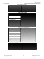
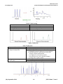
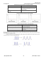
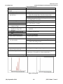
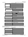
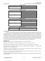
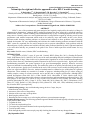
www.jchps.com ISSN: 0974-2115 Journal of Chemical and Pharmaceutical Sciences Instant tips for right and effective approach to solve HPLC trouble shooting P. Ravisankar*1,2, G. Rajyalakshmi1, CH. Devadasu1, G. Devala Rao3 Faculty of Science, Sri Chandrasekharendra Saraswathi Viswa Mahavidyalaya (SCSVMV University), Enathur, Kanchipuram – 631561 (T.N.) India. 2 Department of Pharmaceutical Analysis and Quality Assurance, Vignan Pharmacy College, Vadlamudi, Guntur – 522213 (A.P) India. 3 Department of Pharmaceutical Analysis, KVSR Siddhartha College of Pharmaceutical Sciences, Vijayawada, Andhra Pradesh, India. *Address for Correspondence: E-mail: [email protected], Mobile: 09000199106 1 ABSTRACT HPLC is one of the prominent and potent analytical tool regularly employed for the analysis of drugs in pharmaceutical formulations. Although HPLC method development has been improved by advanced innovative modifications in HPLC column technology and instrumentation day by day even though problems still arise from many sources. Generally when ever more sophisticated unit is used problems cropped up affecting overall system performance each troubled component which needs to be settled by leaps and bounds. In this review article, different trouble shooting common problems are discussed and solutions to those problems while performing method development. For easy understanding and reference the trouble shooting problems encountered with the HPLC system are organized into five major categories such as pressure abnormalities, leaks, problems with the chromatograms, injector problems and remedies and lastly other problems identified by smell, sight and sound and to be settle them and they are presented in the guide in the form of tables apart from textual matter for easy reference. Key words: Possible causes, Solution, HPLC troubleshooting INTRODUCTION The practice of HPLC is now 45 years old. Certainly HPLC (Skoog DA, 2011), (Gurdeep R.Chatwal, 2002), (B.K Sharma, 2013), (Sethi P.D, 2012) is one of the most outstanding analytical techniques for identification and quantification of drugs, either in their active pharmaceutical ingredient or in their formulations throughout the process of their discovery, manufacturing and development. Its chief aim is to provide timely logical process when troubleshooting maximizes the system operation to get good chromatographic practices. Wherever necessary figures are inducted for understanding lucidly. This enables the guide to use quickly and efficiently by the operators with varied experience. Quick tips are included at the end of each section to resolve trouble shooting rapidly even by the less experienced HPLC users also. Analytical methods must be validated to give reliable data for regulatory submissions. These methods are essential for a number of purposes, including testing for QC release, testing of stability samples, testing of reference materials and to provide data to support specifications. Although HPLC method development (Azim Md, 2013), (Vibha Guptha, 2012), (Ravisankar P, 2014), (Ranjit singh, 2013), (Kaushal C, 2010) has been improved by advances column technology and instrumentation problems still arise. The main purpose of this guide is to utilize an easy reference tool to enable to meet suitably the trouble shooting problems (Ravisankar M, 2012), (Gupta V, 2012), Charde MS, 2014), (Runser Dj, 2001), (Christianson, 1997), (Berry VV, 1983), Dolan J.w, 1996), (Shoup R, 1989), (Dolan J.W, 1984, 1985, 1989) immediately in the day to day to run the HPLC system perfectly. Troubleshooting strategy: Any troubleshooting strategy involves 5 steps, they are 1. Identification of the problem 2. Awareness of the causes of the problem 3. Isolation of the exact cause of the problem 4. Rectifying the problem if able 5. Returning the unit to routine use or referring the problem to your maintenance manager Trouble shooting process: The following systematic approach should be followed logically so that the exact cause of the problem can be found. 1. To gather the facts. 2. To check the simplest things first. 3. To compare the performance obtained to the expected performance. 4. To enlist possible causes. 5. Work through the possible causes step-by-step duly checking the outcome from any changes done. July-September 2014 259 JCPS Volume 7 Issue 3 www.jchps.com ISSN: 0974-2115 Journal of Chemical and Pharmaceutical Sciences Locating and correcting the problem: A systematic approach is best to identify any problems when troubleshooting the HPLC system. This guide is organized into five major categories of symptoms to help quickly identify the source of the various problems. Pressure abnormalities are discussed in Table 1-8. Discussion on leaks shown in Table 9- 13. Problems with the chromatograms are shown in Table14 -36 and Figures 1 to 15. Discussion on Injector problems and remedies in Table 37-40. Discussion on other problems detected by smell, sight, and sound in Table 41- 52. Prevention: Many liquid chromatography (LC) problems can be prevented with routine maintenance. For example, replacing pump seals at regular intervals to every pump-seal failure and its associated problems as well as preventive maintenance practices to reduce their frequency. 2. Abnormal pressure: A change in the operating pressure is a sign that there may be a problem. The solution is indicated in the last column against each relevant potential cause to rectify the problem perfectly for proper functioning of the system. Table.1.No pressure reading, no flow Potential cause Solution 1. Power off 1. Turn on power 2. Fuse blown 2. Replace fuse 3. Controller setting or failure 3. a. Verify proper setting b. Repair or replace controller 4. Broken piston 4. Replace piston 5. Air trapped in pump head 5. Degas solvents: bleed air from pump, prime pump 6. Insufficient mobile phase 6. a. Replenish reservoir b. Replace inlet frit if blocked 7. Faulty check valve(s) 7. Replace check valve(s) 8. Major leak 8. Tighten or replace fittings Table.2.No pressure reading, flow is normal. Potential cause Solution 1. Faulty meter 1. Replace meter 2. Faulty pressure transducer 2. Replace transducer Table.3.Steady high pressure Potential cause Solution 1. Flow rate set too high 1. Adjust setting 2. Blocked column frit 2. a. Back flush column (if permitted) b. Replace frit c. Replace column 3. Improper mobile phase; 3. a. Use correct mobile phase precipitated buffer b. Wash column 4. Improper column 4. Use proper column 5. Injector blockage 5. Clear blockage or replace injector 6. Column temperature too low 6. Raise temperature 7. Controller malfunction 7. Repair or replace controller 8. Blocked guard column 8. Remove/replace guard column 9. Blocked in-line filter 9. Remove/replace in-line filter July-September 2014 260 JCPS Volume 7 Issue 3 www.jchps.com ISSN: 0974-2115 Journal of Chemical and Pharmaceutical Sciences Table.4. Steady low pressure Potential cause Solution 1. Flow set too low 1. Adjust flow rate 2. Leak in system 2. Locate leak and correct 3. Improper column 3. Use proper column 4. Column temperature too high 4. Lower temperature 5. Controller malfunction 5. Repair or replace controller Table.5.Pressure climbing Solution 1. Adjust setting 2. a. Back flush column (if permitted) b. Replace frit c. Replace column 3. a. Use correct mobile phase 3. Improper mobile phase; precipitated buffer b. Wash column 4. Improper column 4. Use proper column 5. Injector blockage 5. Clear blockage or replace injector 6. Column temperature too low 6. Raise temperature 7. Controller malfunction 7. Repair or replace controller 8. Blocked guard column 8. Remove/replace guard column 9. Blocked in-line filter 9. Remove/replace in-line filter Potential cause 1. Flow rate set too high 2. Blocked column frit Table.6.Pressure dropping to zero Potential cause Solution 1. Power off 1. Turn on power 2. Fuse blown 2. Replace fuse 3. Controller setting or failure 3. a. Verify proper setting b. Repair or replace controller 4. Broken piston 4. Replace piston 5. Air trapped in pump head 5. Degas solvents: bleed air from pump, prime pump 6. Insufficient mobile phase 6. a. Replenish reservoir b. Replace inlet frit if blocked 7. Faulty check valve(s) 7. Replace check valve(s) 8. Major leak 8. Tighten or replace fittings 9. Faulty meter 9. Replace meter 10. Faulty pressure transducer 10. Replace transducer Table.7.Pressure dropping, but not to zero Potential cause Solution 1. Flow set too low 1. Adjust flow rate 2. Leak in system 2. Locate leak and correct 3. Improper column 3. Use proper column 4. Column temperature too high 4. Lower temperature 5. Controller malfunction 5. Repair or replace controller July-September 2014 261 JCPS Volume 7 Issue 3 www.jchps.com Potential cause 1. Air in pump 2. Faulty check valve(s) 3. Pump seal failure 4. Insufficient degassing 5. Leak in system 6. Using gradient elution ISSN: 0974-2115 Journal of Chemical and Pharmaceutical Sciences Table.8.Pressure cycling Solution 1. a. Degas solvent b. Bleed air from pump 2. Replace check valve(s) 3. Replace pump seal 4. a. Degas solvent b. Change degassing methods (use degasser on-line degasser) 5. Locate leak and correct 6. Pressure cycling is normal due to viscosity changes 3. Leaks: Leaks are usually stopped by proper suitable tightening or replacing the loose fittings. One must be aware, particularly that if metal compression fittings are over tightened may allow leaks and plastic finger tights may wear out quickly. If a fitting leak does not stop when the fitting is tightened a little, take off the fitting out and inspect the damage (e.g., distorted ferrule or particles on the sealing surface) damaged fittings should be discarded and replaced. Table.9.Leaky fittings Potential cause Solution 1. Loose fitting 1. Tighten 2. Stripped fitting 2. Replace 3. Over tightened fitting 3. a. Loosen and retighten b. Replace 4. Dirty fitting 4. Disassemble and clean Table.10.Leaks at pump Potential cause 1. Loose check valves 2. Loose fittings 3. Mixer seal failure 4. Pump seal failure 5. Pressure transducer failure 6. Pulse damper failure 7. Proportioning valve failure 8. Purge valve Solution 1. a. Tighten check valve (do not over tighten) b. Replace check valve 2. Tighten fittings (do not over tighten) 3. a. Replace mixer seal b. Replace mixer 4. Repair or replace 5. Repair or replace 6. Replace pulse damper 7. a. Check diaphragms, replace if leaky b. Check for fitting damage, replace 8. a. Tighten valve b. Replace purge valve Table.11.Injector leaks Potential cause Solution 1. Rotor seal failure 1. Rebuild or replace injector 2. Blocked loop 2. Replace loop 3. Loose injection-port seal 3. Adjust 4. Improper syringe-needle diameter 4. Use correct syringe 5. Waste-line siphoning 5. Keep waste line above surface waste 6. Waste-line blockage 6. Replace waste line July-September 2014 262 JCPS Volume 7 Issue 3 ISSN: 0974-2115 Journal of Chemical and Pharmaceutical Sciences www.jchps.com Table.12.Column leaks Potential cause 1. Loose end fitting 2. Column packing in ferrule 3. Improper frit thickness Solution 1. Tighten end fitting 2. Disassemble, rinse ferrule, reassemble 3. Use proper frit (see Frit selection guide chart) Table.13.Detector leaks. Potential cause 1. Cell gasket failure Solution 1. a. Prevent excessive backpressure b. Replace gasket 2. Replace window(s) 3. Tighten or replace 4. Replace waste line 5. Rebuild or replace 2. Cracked cell window(s) 3. Leaky fittings 4. Blocked waste line 5. Blocked flow cell 4. Problems with the chromatogram: Many problems in an HPLC system is sign to show the changes in the chromatograms. Some of these can be solved by replacing the non functioning components of equipment or effecting modifications to the assay procedures. Selection of the suitable column and mobile phase are key parts to obtain good chromatography. Figure 1. Peak tailing. Due to secondary retention effects, Residual silanol interactions, and small peak elution on tail of large peak yields some irregular peaks tail. Due to extra column effects, contamination build up on column inlet, heavy metals and bad column yields all imperfect peaks tails. Table.14.Peak tailing Potential cause 1. Blocked frit 2. Column void 3. Interfering peak 4. Wrong mobile-phase pH 5. Sample reacting with active sites July-September 2014 Solution 1. a. Reverse flush column (if allowed) b. Replace inlet frit c. Replace column 2. a. Fill void 3. a. Use longer column b. Change mobile-phase and/or column/ selectivity 4. a. Adjust pH b. For basic compounds, a lower pH usually provides more symmetric peaks 5. a. Add ion pair reagent or volatile basic b. Change column modifier 263 JCPS Volume 7 Issue 3 ISSN: 0974-2115 Journal of Chemical and Pharmaceutical Sciences www.jchps.com Figure 2. Peak fronting Table.15.Peak fronting Potential cause 1. Low temperature 2. Wrong sample solvent 3. Sample overload Solution 1. Increase column temperature 2. Use mobile phase for injection solvent 3. Decrease sample concentration Figure.3.Split peaks Table.16.Split peaks Potential cause 1. Contamination on guard or analytical column inlet 2. Sample solvent incompatible with mobile phase Solution 1. a. Remove guard column and attempt analysis b. Replace guard if necessary c. If analytical column is obstructed, reverse and flush d. If problem persists, column may be fouled with strongly retained contaminations e. Use appropriate restoration procedure f. If problem persists, inlet is probably plugged g. Change frit or replace column 2. a. Change solvent; whenever possible b. Inject samples in mobile phase Figure.4. Distortion of larger peaks July-September 2014 264 JCPS Volume 7 Issue 3 ISSN: 0974-2115 Journal of Chemical and Pharmaceutical Sciences www.jchps.com Table.17. Distortion of larger peaks Potential cause 1. Sample overload Potential cause 1. Wrong injection solvent Potential cause 1. Extra-column effects Solution 1. Reduce sample size Table.18.Distortion of early peaks Solution 1. a. Reduce injection volume b. Use weaker injection solvent Table.19.Tailing, early peaks more than later ones Solution 1. a. Re plumb system (shorter, narrower tubing) b. Use smaller volume detector cell Table.20.Increased tailing as k' increases Potential cause Solution 1. Secondary retention effects, reversed-phase mode 1. a. Add tri ethylamine (basic samples) b. Add acetate (acidic samples) c. Add salt or buffer (ionic samples) d. Try a different column 2. Secondary retention effects, normal-phase mode 2. a. Add tri ethylamine (basic compounds) b. Add acetic acid 3. Secondary retention effects, ion-pair 3. a. Add tri ethylamine (basic samples) Potential cause 1. Inadequate buffering Table.21.Acidic or basic peaks tail Solution 1. a. Use 50–100 mm buffer concentration b. Use buffer with pKa equal to pH of mobile phase Figure 5. Extra peaks Table 22. Extra peaks. Potential cause Solution 1. Other components in sample 1. Normal 2. Late-eluting peak from previous 2. a. Increase run time or gradient slope injection b. Increase flow rate 3. Vacancy or ghost peaks 3. a. Check purity of mobile phase b. Use mobile phase as injection solvent c. Reduce injection volume July-September 2014 265 JCPS Volume 7 Issue 3 ISSN: 0974-2115 Journal of Chemical and Pharmaceutical Sciences www.jchps.com Table.23. Retention time drifts Potential cause 1. Poor temperature control 2. Mobile phase changing 3. Poor column equilibration Potential cause 1. Flow rate change 2. Air bubble in pump 3. Improper mobile phase Solution 1. Thermostat column 2. Prevent change (evaporation, reaction etc) 3. Allow more time for column equilibration between runs Table.24. Abrupt retention time changes Solution 1. Reset flow rate 2. Bleed air from pump 3. a. Replace with proper mobile phase b. Set proper mobile phase mixture on controller Baseline irregularities: Figure6.Non-cyclic noise-fluid path problems Table.25.Non-cyclic noise-fluid path problems Potential cause Solution 1. Air in mobile phase, detector cell, or 1. a. Degas mobile phase pump b. Flush system to remove air from detector cell or pump 2. column contamination 2. Replace with a new column 3. Air bubbles in the flow path 3. Prime the pump once again and ensure that all solvents thoroughly degassed Figure.7.Non-cyclic noise-detector electronics problems July-September 2014 266 JCPS Volume 7 Issue 3 www.jchps.com ISSN: 0974-2115 Journal of Chemical and Pharmaceutical Sciences Table.26.Non-cyclic noise-detector electronics problems Potential cause Solution 1. Detector not stable 1. Allow sufficient time to stabilize 2. Detector lamp malfunction 2. If the lamp energy is below that recommended for normal detector operation replace the lamp 3. Contaminated/ Scratched reference 3. Replace the working electrode electrode Figure.8.Cyclic noise-detector related problems Table.27.Cyclic noise-detector related problems. Potential cause Solution 1.Long term detector temperature problems 1. The heater cycles on and off to maintain the detector temperature 2. Ambient temperature fluctuations 2. Stabilize the air temperature around the instrument and allow the system to return to equilibrium 3. Contaminated reference electrode 3. Replace the working electrode Broad peaks: Due to loss of column efficiency, column void and large injection volume causes all peaks become broad which shows imperfect results. Owing to Possible late elution from previous sample (ghost peak), high molecular weight sample- protein or polymer causes to become some peaks broad. Figure.9.Broad peaks July-September 2014 267 JCPS Volume 7 Issue 3 www.jchps.com ISSN: 0974-2115 Journal of Chemical and Pharmaceutical Sciences Table.28.Broad peaks Potential cause 1. Mobile-phase composition changed 2. Mobile-phase flow rate too low 3. Leaks (especially between column and detector) 4. Detector settings incorrect 5. Extra-column effects: a. Column overloaded b. Detector response time or cell volume too large c. Tubing between column and detector too long or ID too large d. Recorder response time too high 6. Buffer concentration too low 7. Guard column contaminated 8. Column contaminated/worn out; low plate number 9. Void at column inlet Solution 1. Prepare new mobile phase 2. Adjust flow rate 3. a. Check system for injector leaks Check for column leaks; Check for detector leaks b. Check for loose fittings c. Check pump for leaks, salt build-up and unusual noises d. Change seals if necessary 4. Adjust settings 5. a. Inject smaller column (e.g., 10 µL vs. 100 µL) or 1:10 and 1:100 dilutions of sample b. Reduce response time or use smaller cell c. Use as short a piece of 0.007–0.010 inch ID tubing as practical d. Reduce response time 6. Increase concentration 7. Replace guard column 8. a. Replace column with new one of same type b. If new column provides symmetrical peaks, flush old column with strong solvent 9. Open inlet end and fill void or replace column 10. Peak represents two or more Poorly resolved solvents 11. Column temperature too low 10. Change column type to improve separation 12. Detector time constant too large 12. Use smaller time constant 11. Increase temperature; do not exceed 75°C unless higher temperatures are acceptable to column manufacturer Figure.10.No peaks July-September 2014 268 JCPS Volume 7 Issue 3 www.jchps.com ISSN: 0974-2115 Journal of Chemical and Pharmaceutical Sciences Table.29. No peaks Potential cause Solution 1. Wrong sample being injected 1. Inject correct sample 2. The detector not being switched on (or) 2. Switch on the detector blockage between the injector and detector lines 3. Sample or mobile phase preparation has 3. preparation of mobile phase or sample been performed correctly has been performed correctly Figure.11.Smaller than expected peaks Table.30. Smaller than expected peaks Potential cause Solution 1. Wrong injection volume 1. Inject the correct volume 2. Detector problem 2. Zero the detector output 3. Sample too viscous 3. Dilute the sample or decrease the rate at which the syringe draws the sample 4. Sample loop incorrect 4. Change the sample loop to the correct volume in the one in-situ is incorrect Figure.12.Early eluting peaks broad Table 31. Early eluting peaks broad. Potential cause Solution 1. Sample over load 1.Dilute the sample or inject a lower volume to stop equilibrium disruption 2. Detector time constant incorrect 2.Correct the detector time constant July-September 2014 269 JCPS Volume 7 Issue 3 ISSN: 0974-2115 Journal of Chemical and Pharmaceutical Sciences www.jchps.com Figure.13.Flat topped peaks Table.32.Flat topped peaks Potential cause 1. Large injection volume of dilute sample 2. Recorder input error Solution 1. Injection of small volume of dilute sample 2. Adjust the recorder input voltage Figure.14.Negative peaks Table.33.Negative peaks Potential cause 1. Highly adsorbing mobile phase 2. Ion pair separation only Solution 1. Dissolve the sample in mobile phase 2. Dissolve the sample in mobile phase Table.34.Loss of resolution Potential cause 1. Mobile phase contaminated/ deteriorated (causing retention time to change) Solution 1. Prepare new mobile phase 2. Obstructed guard or analytical column 2. a. Remove guard column and attempt analysis b. Replace guard if necessary c. If analytical column is obstructed, reverse and flush if problem persists, column may be fouled with strongly retained contaminants d. Use appropriate restoration procedure if problem persists, inlet is probably plugged e. Change frit or replace column Table.35.All peaks too small Potential cause 1. Detector attenuation too high 2. Detector time constant too large 3. Injection size too small 4. Improper recorder connection July-September 2014 Solution 1. Reduce attenuation 2. Use smaller time constant 3. Use larger sample loop 4. Use correct connection 270 JCPS Volume 7 Issue 3 ISSN: 0974-2115 Journal of Chemical and Pharmaceutical Sciences www.jchps.com Potential cause 1. Detector attenuation too low 2. Injection size too large 3. Improper recorder connection Table.36.All peaks too large Solution 1. Use larger attenuation 2. Use smaller sample loop 3. Use correct connection Figure.15.Ghost Peaks 5. Problems with the injector: The problems are usually detected while using the injection valve. Table.37.Manual injector, hard to turn Potential cause Solution 1. Damaged rotor seal 1. Rebuild or replace valve 2. Rotor too tight 2. Adjust rotor tension Potential cause 1. Valve misaligned 2. Blocked loop 3. Dirty syringe 4. Blocked lines Table.38.Manual injector, hard to load Solution 1. Adjust alignment 2. Replace loop 3. Clean or replace syringe 4. Clear or replace lines Potential cause 1. No air pressure (or power) 2. Rotor too tight 3. Valve misaligned Table.39.Auto injector will not turn Solution 1. Supply proper pressure (power) 2. Adjust 3. Adjust alignment Potential cause 1. Blockage 2. Jammed mechanism 3. Faulty controller Table.40.Auto injector, other problems Solution 1. Clear or replace blocked portion 2. See service manual 3. Repair or replace controller 6. Problems detected by smell, sight and sound: All senses must be used to identify HPLC problems. Habit of taking a few minutes each day need to be cultivated to expose all senses except taste to know how far the HPLC performs properly which help to identify problems quickly. For example, often a leak can be detected by smell before it is seen. The majority of problems are identified by sight which is shown the following tables. July-September 2014 271 JCPS Volume 7 Issue 3 ISSN: 0974-2115 Journal of Chemical and Pharmaceutical Sciences www.jchps.com Potential cause 1. Leak 2. Spill Table.41.Solvent smell Solution 1. a. Check system for injector leaks b. Check system for loose fittings c. Check pump for leaks, salt build-up, unusual noises d. Change pump seals if necessary 2. a. Check for overflowing waste container b. Locate spill and clean up Table.42."Hot" smell Potential cause 1. Overheating module Solution 1. a. Check for proper ventilation, adjust b. Check temperature setting, adjust c. Shut module off, see service manual Table.43.Abnormal meter readings Potential cause Solution 1. Pressure abnormality 1. Mention in Section 2 2. a. Check settings, adjust 2. Column oven problem b. See service manual 3. Detector lamp failing 3. Replace lamp Table.44.Warning lamps Potential cause 1. Pressure limit exceeded 2. Other warning lamps Solution 1. a. Check for blockage b. Check limit setting, adjust 2. See service manual Table.45.Warning buzzers Potential cause 1. Solvent leak/spill 2. Other warning buzzers Potential cause 1. Bearing failure 2. Poor lubrication 3. Mechanical wear Solution 1. Locate and correct 2. See service manual Table.46.Squeaks and squeals Solution 1. See service manual 2. Lubricate as necessary 3. See service manual 7. Details of Key problem areas and their preventive maintenance: The LC's operator and service manuals may have additional suggestions for preventive maintenance in addition to the causes and solutions detailed in the following tables mentioned bellow. Table.47.Reservoir Potential cause Solution 1. Blocked inlet frit 1. a. Replace (3–6 months) b. Filter mobile phase, 0.5 µm filter 2. Gas bubbles 2. Degas mobile phase Table.48.Pump Potential cause Solution 1. Air bubbles 1. Degas mobile phase 2. Pump seal failure 2. Replace (3 months) 3. Check valve failure 3. Filter mobile phase; use inlet-line frit; keep spare July-September 2014 272 JCPS Volume 7 Issue 3 www.jchps.com ISSN: 0974-2115 Journal of Chemical and Pharmaceutical Sciences Table.49.Injector Potential cause 1. Rotor seal wear Solution 1. a. Do not over tighten b. Filter samples Table.50.Column Potential cause 1. Blocked frit 2. Void at head of column Solution 1. a. Filter mobile phase b. Filter samples c. Use in-line filter and/or guard column 2. a. Avoid mobile phase pH >8 b. Use guard column c. Use pre column (saturator column) Table.51.Detector Potential cause Solution 1. Lamp failure; decreased detector 1. Replace (6 months) or keep spare lamp response; increased detector noise 2. Bubbles in cell 2. a. Keep cell clean b. Use restrictor after cell c. Degas mobile phase Table.52.General Potential cause Solution 1. Corrosive/abrasive damage 1. Flush buffer from LC and clean when not in use CONCLUSION HPLC is the widely utilized technique for the routine analysis of the drugs in pharmaceutical dosage forms. Several problems may occur while performing the method development by RP-HPLC. The above explained trouble shooting guidelines will render immense help to the analyst to maintain the HPLC system to overcome problems if any happened and also keep the system in smooth way of running which reduces the operation cost. The above said tips will assist to maintain the HPLC system perfectly and keeps the system out of routine problems which lessen the maintenance cost due to highest quality performance of the system. It leads to successful operation of the HPLC system if the principle “Commence with the suitable and apt questions seek the appropriate answers and ultimately the correct answers obtained will paves the way towards required solutions” is perfectly applied. REFERENCES Skoog DA, West DM, Holler FJ, Instrumental analysis, 2011, 8th edition, 896-906. Gurdeep R.Chatwal, Instrumental methods of chemical analysis, 2002, 5th edition, 2.566-2.568. B.K. Sharma, Insturmental methods of chemical analysis, 29th edition, Goyel publications, 2013, 286-385. Sethi P.D. (2012) ‘Quantitative Analysis of Drugs in Pharmaceutical Formulations’. 4th Edition, CBS Publishers Pvt. Ltd., New Delhi.22-43. Ravisankar M, Sereya K, Ramaiah K, A review on preventive maintenance and trouble shooting of HPLC, International research journal of pharmacy, 2012, 3(9), 34-38. Gupta V, Jain AD, Gupta K, Development and validation of HPLC method, International research journal of pharmaceutical & applied sciences, 2012, 2(4), 17-25. Azim Md, Sabiretal, Method development and validation, International research journal of pharmaceutical analysis, 2013, 4(4), 40-46. July-September 2014 273 JCPS Volume 7 Issue 3 ISSN: 0974-2115 Journal of Chemical and Pharmaceutical Sciences www.jchps.com Vibha gupta et al, Development and validation of HPLC method, international research journal of pharmaceutical applied sciences, 2012, 2(4), 17-25. Ravisankar P, Gowthami S, Devala Rao G.,A review on analytical method development, IJRPB, 2014, 2(3), 11831195. Ranjit singh et al, HPLC method development and Validation, J Pharm Educ. Res, 2013, 4(1), 26-33. Kaushal C, Srivasthava B, Aprocess of method development:A chromatographic approach, j Chem Pharm Res. 2010. 2 (2), 519-545. M. S. Charde, R. T. Bande, A. S. Welankiwar, J. Kumar and R. D. Chakole, Review: common trouble shooting problems in RP-HPLC, IJAPA Vol. 4 Issue 1 (2014) 07-11. Runser DJ, maintaining & troubleshooting HPLC systems, 2001, 10-16. Christianson and Dolan J.W, LC-GC, 1997, 15 (10), 928-924. Berry V.V, Dolan J.W LC, Liq.Chromatogr. HPLC Mag. (1983), 1, 406-407. Dolan J.W, LC-GC, 1996, 14 (5), 378-382. Shoup R and Bogdan M, LC-GC, 1989, 7 (9), 742-744. Dolan J.W, LC trouble shooting, 1989, 7, 224. Dalan J.W, L.C. Liq.Chromatogr. HPLC Mag. 1984, 2, 834-836. Dalan J.W, Trouble shooting, L.C Liq. Chromatogr. HPLC Mag. 1985, 3, 1050-1052. Tips and tricks of HPLC trouble shooting. Agilent technologies available from: www.chem.agilent.com July-September 2014 274 JCPS Volume 7 Issue 3