1
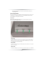
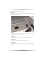
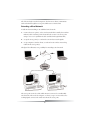
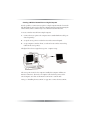
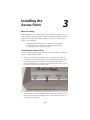
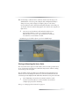
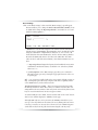
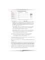
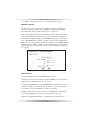
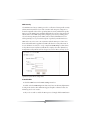
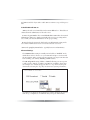
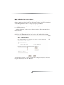
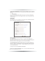
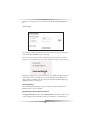
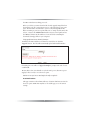
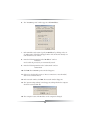
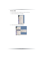
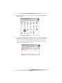
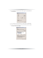
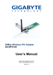
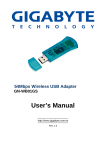
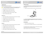
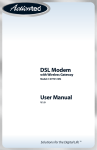
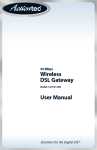
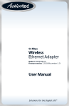
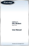
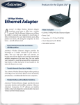
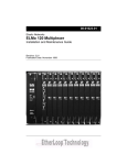
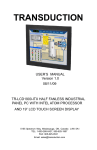
54 Mbps
Wireless
Access Point
Model #: GT701AP
Firmware version: 3.0.1.0.5-GT701-AP
User Manual
Solutions for the Digital Life™
Table of Contents
1 Introduction
3
Package Contents
Minimum System Requirements
Access Point Features
Technical Support
2 Wireless Networking Basics
3
3
4
6
7
Creating a Wireless Network
Extending a Wired Network
7
8
3 Installing the Access Point
10
Before Installing
Connecting the Access Point
Placing or Mounting the Access Point
4 Setting Up the Access Point
Making a Connection
Accessing & Viewing the Control Panel
Basic Settings
Security Settings
Advanced Settings
10
10
11
12
13
13
15
17
19
6 Troubleshooting and FAQ
24
Troubleshooting
Frequently Asked Questions
24
24
A Setting Up Static IP
28
Windows 98 and 98 SE
Windows Me
Windows 2000
Windows XP
28
32
35
39
B Specifications
Notices
43
48
Regulatory Compliance Notices
Modifications
Limited Warranty
48
48
50
1
2
1
Introduction
Thank you for purchasing the Actiontec 54 Mbps Wireless Access Point. We’ve
worked hard to make this Access Point the simplest, most convenient way to create
a wireless network for your home office or small business. If you want to take your
computing to the next level, the Actiontec 54 Mbps Wireless Access Point is one of
the keys to your success.
This User Guide will show you how to set up the Actiontec 54 Mbps Access Point,
and how to customize its configuration to get the most out of your new product.
Package Contents
s
Actiontec 54 Mbps Access Point
s
Power adapter
s
Gray Crossover Ethernet cable
s
Installation CD (includes user manual)
s
Quick start guide
Minimum System Requirements
s
s
Computer(s) with the following:
û
a 10/100 Mbps Ethernet connection
û
Microsoft Windows 98, 98 Second Edition (SE), Millennium Edition (Me),
2000, or XP
û
Internet Explorer 4.0 or higher (5.x recommended), or Netscape
Navigator 4.0 or higher (4.7 recommended)
TCP/IP network protocol installed
3
s
All computers included on the wireless network must have wireless networking capabilities
Access Point Features
The Access Point has a series of LEDs on its front panel, and a series of ports on its
rear panel. It is recommended that the user become familiar with these features
before installing or setting up the Access Point.
Front Panel
There are three LEDs (light emitting diodes) on the front panel of the Access
Point, as shown in the figure, below.
Power LED
The Power LED glows red when power is supplied to the Access Point. When it
blinks green, the Access Point is going through its initialization process. Steady
green indicates the Access Point is ready.
Ethernet LED
The Ethernet LED glows green to indicate that your Access Point “sees” an active
Ethernet connection.
Wireless LED
The Wireless LED glows green when the Access Point is ready to use. It will blink
4
intermittently when there is wireless activity.
Rear Panel
The Access Point has a Power Connector, A LAN (Ethernet) Port, an Antenna Jack,
and a Reset button on its rear panel.
LAN Port
The Ethernet (LAN) port is used to connect the Access Point to a hub or router
with the Gray Crossover Ethernet cable.
Power Port
The Power Port is used to connect the Access Point’s Power Adapter.
Antenna Jack
The Antenna Jack connects the Access Point to its antenna.
Reset Button
The Reset button is used to reset the Access Point and restore the factory default
settings.
5
Technical Support
Actiontec Electronics, Inc., prides itself on making durable, high-quality, highperformance products. If you need assistance, the Actiontec Technical Support
Department is available to provide professional support 24 hours a day, every day,
except major holidays.
Actiontec Electronics, Inc.
760 N. Mary Avenue
Sunnyvale, CA 94086
Technical Support
Phone: 1-888-436-0657 (USA), 0845 65 80411 (UK)
Email: http://support.actiontec.com/email_support/support_form.php
6
Wireless
Networking Basics
2
Wireless networking connects computers to each other using radio signals rather
than wires. This allows users the freedom to move around and work anywhere
within the range of the wireless network. A wireless network consists of two elements - Clients and Access Points.
• A Client is a computer or any other device equipped with a wireless network
adapter, such as the Actiontec 54 Mbps Wireless PC Card .
• An access point is a device, like your Actiontec 54 Mbps Wireless Access
Point, that connects the clients with the network and each other.
The following sections give an overview of the options available when
setting up a wireless network.
Creating a Wireless Network
Creating a wireless network involves two basic steps:
1. Setting up an access point to send and receive wireless network signals.
2. Setting up computers to send and receive wireless network signals from the
access point(s).
A typical wireless network may look similar to the one in the figure, below.
7
All of the wirelessly networked computers (also known as clients) communicate
with each other through the access point, which acts as a wireless hub.
Extending a Wired Network
To add wireless networking to an established wired network:
1. Connect the access point(s) to the wired network. This is usually done with an
Ethernet cable connecting a wired network hub or router to an access point
using a “cross-over” style Ethernet cable (included in the Quick Start Kit).
2. Set up the access point(s) to send and receive wireless network signals.
3. Set up computers (wireless clients) to send and receive wireless network signals from the access point(s).
The figure below illustrates one possibility for extending a wired network:
The access point is wired to a hub, which in turn is connected to a traditionally
wired network. The notebook computer (or client), set up to receive wireless networking signals, can access the wired network via the access point.
8
Creating a Wireless Network from a Single Computer
It is also possible to connect an access point to a single computer, instead of a network
hub. This method can be used to share the computer’s Internet connection among the
wireless clients, and is a common way to use a wireless network in the home.
To create a wireless network from a single computer:
1. Connect the access point to the computer. Use a standard Ethernet cable (purchased separately).
2. Set up the access point to send and receive wireless network signals.
3. Set up computers (wireless clients) to send and receive wireless network signals from the access point(s).
The figure below shows a typical access point - computer setup:
The access point is wired to the computer (usually, this computer will have an
Internet connection). The notebook computer (wireless client) can access the
wired computer, as well as use the Internet connection to surf the Web.
Next, go to “Installing the Access Point” on page 10 to connect the Access Point.
9
3
Installing the
Access Point
Before Installing
Before installing the Access Point, be aware that this device can subject the user to
electrical shock. Follow the guidelines in this manual and the manuals of any other
equipment used during the installation. Failure to do so may result in injury or
damage to the equipment.
Important: This Access Point is a 2.4 GHz low-power RF device.
It is intended for home and office use in all EU member states
except France, where restrictive use applies.
Connecting the Access Point
To connect the Access Point to a network hub, switch, or computer (via Ethernet
cable), use the following procedure:
1. Plug one end of the Power Adapter into the Power port on the back of the
Access Point, and the other end into a power outlet. The Power LED on the
front panel of the Access Point will be red until the initialization process
begins, then blinks green. It will turn steady green when the device is ready
for service. (This may take up to 30 seconds)
2. If connecting to a network hub or switch, plug one end of a “cross-over” type
Ethernet cable (not included with the Access Point) in the LAN port on the
back of the Access Point , and plug the other end into the hub or switch. See
the figure on the next page.
10
2a. If connecting to a Router, hub or switch for wireless network usage or for
administration of an access point (using the Web Configuration Utility to
change an access point’s settings, for example), plug one end of Gray
Crossover Ethernet cable (included in this Quick Start Kit) in the LAN port
on the back of the Access Point, and plug the other end into the computer. See
figure below.
+
Note: Do not use the Ethernet cable included with the Access
Point Quick Start Kit to connect to a computer. This Gray
Ethernet cable is a “crossover” type, and is used to connect the
Access Point to a network hub or switch.
An Ethernet port looks like a phone port, but is slightly larger.
Placing or Mounting the Access Point
The Access Point can be placed on a flat surface (such as a desktop). Ensure there
are no obstructions around the Access Point that may interfere with the sending
and receiving of wireless signals.
The Access Point can also be mounted on a wall. On the bottom panel of the Access
Point are four screw mounting holes. Insert two screws into the wall, and ensure the
screw heads protrude slightly from the wall surface. Mount the access point on the wall.
+
Note: If planning to mount the Access Point in a hard-to-reach
location, ensure the cables are connected and the Access Point is
configured properly before mounting.
Next, go to “Setting Up the Access Point” on page 12.
11
4
Setting Up the
Access Point
The 54 Mbps Wireless Access Point is shipped ready for immediate use. Its factory
default settings allow the user to access the wireless network after making a few
adjustments to the wireless clients to recognize its pre-programmed SSID.
You should note however that in its default mode, your Access Point has its security options disabled and is pre-configured to run on channel # 9 of its 11 available
channels. In some cases, you may have to change security settings, radio channels,
IP addresses, client access privileges or other options, so it will work properly in
your facility. In this case, you will have to reconfigure the default settings using the
unit’s internal web-based “control panel” that you can view using any standard
web browser program, such as MS Internet Explorer or Netscape,.
Configuring the Access Point
Making A Connection
Configuring the Access Point’s settings requires you to to make a connection to
the unit’s Ethernet port access the unit’s web-based control panel or via its wireless
link. This can be done in one of two ways:
1.
Connecting your computer to the Access Point via an Ethernet router.
This is the preferred technique if you have a router port available in your network. Simply plug one end of a cross-over Ethernet cable (included with the
Access Point) in the LAN port on the back of the Access Point, and plug the
other end into the hub or switch. Details may be found in sub-section 2 of the
previous chapter.
2.
Connecting your computer directly to the Access Point via an Ethernet cable.
If you need to connect directly to the Access Point via your computer, plug
one end of a “straight-through” Ethernet cable (purchased separately) in the
LAN port on the back of the Access Point, and plug the other end into the
computer. Details may be found in sub-section 2a of the previous chapter.
3.
Connecting to the Access Point via a wireless connection.
You can also access the control panel by associating with the access point. If
you are running Windows 98 through Windows 2000, simply set the SSID for
the WiFi client in your computer to “Actiontec” (case sensitive), and select the
“Infrastructure” operating mode. For Windows XP systems, simply right
click on network icon in lower right, select "view available wireless networks”
from the menu, and then select "Actiontec" from list. Click Apply and close.
12
Your connection to the Access Point should be established and you are ready
to access to the unit’s control panel.
Accessing & Using The Control Panel
Making Sure Your Computer Can Talk To The Access Point .
The Access Point’s control panel has an internal IP address of 192.168.0.240 which
enables any standard web browser to view and adjust its settings. If you are connected to your access point via an Actiontec brand router, it has an address that is
within the same subnet address range. This means that you are ready to “talk” to
the control panel and don’t need to read this section and should proceed directly
to the next section “Viewing The Control Panel” a bit further down on this page.
If, however, you are using another brand of router (Linksys and some other products), the you may need to configure your computer’s NIC card with a static IP
address that is within the range of the access point’s control panel. This is true
whether you are making a wired or wireless connection to the unit.
If you are unsure of your router’s subnet address range, you can try talking to the
control using the procedures in the next section “Viewing The Control Panel” a bit
further down on this page. If this does not work, follow the procedures outlined in
Appendix A - “Setting Up A Static IP Address” on page 28 before attempting to
access the control panel again.
NOTE: If you are making a “direct” connection to your computer without going
through a router, you will also need to adjust your NIC card’s IP address using this
procedure.
Viewing The Control Panel
Simply plug one end of a “cross-over” type Ethernet cable (purchased separately) in
the LAN port on the back of the Access Point, and plug the other end into the hub
or switch. Details may be found in sub-section 2 of “Connecting The Access Point”
in the previous chapter.
1.
Open your Web browser.
2.
In the address bar enter http://192.168.0.240 then press <enter>.
NOTE: The Username/Password setting is disabled when the Access Point is shipped
from the factory to allow for easy first-time access to the control panel. If you
receive the Access Point after it has had a password set but do not know what it is,
you will not be able to access the control panel. You can disable the password
mode by physically resetting the access point. This is done by by holding the
“Reset” button on the back of the Access Point for 15 seconds and releasing it.
13
3. The "Welcome" screen appears. From this point, you can configure the Access
Point from one of its seven sub-menus
Setting the IP Address
The IP Address section allows you to setup IP Address, either DHCP or static IP
mode. NOTE: Changing these settings is not required in most applications
Click on the “IP Address” selection and the “IP Address” page will appear.
Actiontec recommends keeping the unit’s default static IP address
(192.168.0.240), but if it conflicts with another device in the network, you can
enter a new address in the “IP Address” text box.
If your network requires the Access Point to run in Dynamic Host
Configuration Protocol (DHCP) mode which dynamically assigns an IP address,
you can change these settings from this screen.
14
Basic Settings
Click on the “Basic Settings” selection and the “Basic Settings” page will appear.
This menu allows you to change the Wireless Network Name (ESSID*), from
its default value, change the Operating Channel**, and enable one of several
available security options***.
* ESSID is the network name assigned to the wireless network. The factory
default setting is “ACTIONTEC.” The ESSID value can be modified if needed,
using any combination of alphanumeric characters (i.e., A-Z, a-z, 0-9). All
clients must have this same ESSID value. (For the Actiontec 802.11g Wireless
PC Card, the ESSID value must be the same as the SSID value. The SSID
value can also be called the Network Name.) Note that the ESSID is case sensitive.
s
** Operating Channel assigns the frequency band at which the Access Point
communicates. In the United States, use channels 1-11. (The factory default
value is set to 1.)
*** Security Options on the “Basic Settings” page allow you to activate the
following security options by selecting the appropriate buttons on the control panel page:
Off - or no encryption enabled. This is the Access Point’s default security setting, Selecting this option allows any computer with wireless capability and the
correct ESSID value to join the wireless network.
Wired Equivalent Privacy (WEP) - This is an encryption method used with
the 802.11g standard to ensure data security over wireless networks. After activating WEP on the Access Point, a client can join the network only if these same
keys are entered in that client’s wireless encryption scheme.
To Activate WEP, select the “WEP” button, and then click on the “Next” button.
Your browser will then display the “WEP Key” menu page.
Although WEP only uses one key at a time, the WEP Key menu allows you to
store up to four keys which can be activated for use by clicking the button next
to the key you wish to use. You can choose from two levels of WEP encryption
(64-bit and 128-bit) from the pull-down menus alongside each key entry.
15
64-bit WEP uses a key made from of five hexadecimal digit pairs. A hexadecimal digit consists of an alphanumeric character ranging from 0-9 or A-F.
An example of a 64-bit WEP key is: 4E-A3-3D-68-72. To create a set of 64bit WEP keys, enter five hexadecimal digit pairs into the desired Key text
box (Key 1, Key 2, Key 3, Key 4).
128 bit WEP Key is just like the 64-bit key except that it uses 13 hexadecimal
pairs to provide more secure encryption. To create a 128-bit WEP key,
enter 13 hexadecimal digit pairs in the Key text box.
256 bit WEP Key is just like the 64-bit key except that it uses 29 hexadecimal
pairs to provide more secure encryption. To create a 256-bit WEP key,
enter 29 hexadecimal digit pairs in the Key text box.
Not all wireless PC Cards support 128-bit or 256-bit WEP.
+ NOTE:
Ensure all wireless PC Cards installed in the clients support the
version of WEP you want to use before activating.
The Authentication Type controls how a client connects, or “authenticates” itself
with the Access Point when WEP is enabled.
Open mode allows any client to try to authenticate to THE ACCESS POINT using
a WEP key.
Shared Key mode provides tighter security by requiring that a wireless client also
have a digital certificate that authorizes it to talk with the THE ACCESS POINT
before it is allowed to authenticate itself. In Shared Key mode, the client will issue
a digital certificate or second key to that the Access Point will pass through
through to a server for authentication. The Access Point however is just a conduit
and does not do any processing of the certificate itself. Do not enable this feature
unless your network supports shared authentication features.
16
The "Both" setting allows stations to use either authentication mode .
WEP 802.1x Security
The 802.1x protocol is a collection of security features intended primarily for
enterprise computing environments. It simplifies management by applying the
same authentication protocol for wired and wireless connections.
802.1x offers an effective framework for authenticating user traffic to a protected
network, and dynamically varying encryption of keys, and supports multiple
authentication methods. It employs a Server Address that ties it to an associated
server, a Port Number that designates a specific connection, and a Shared Secret
Word that is used as a private key by all system elements. The Group Key Interval
setting controls the number of minutes between which the group key is automatically changed across the whole network, and is used for broadcast and multi-packet operations.
To Enable 802.1x:
1. Click the 802.1x button in the Basic Settings menu box.
2. Enter the radio server's IP address in the Server Address box - This address is
obtained from the administrator of the radio server.
3. Enter the port number. The normal default value is 1812 unless the network
administrator changes it to match a particular radio server’s port setting. In this
case, consult your network administrator for the proper setting.
4. Enter the shared secret word, which can be any alphanumeric string, and is
case sensitive. NOTE: Client and server must have the same secret word.
5. Enter the group key interval value - typically between 3 and 60 minutes.
17
WPA Security
The WiFi Protected Access (WPA) protocol is a collection of interoperable security
enhancements intended for use in both consumer and enterprise settings. It is a
forward-compatible subset of the upcoming 802.11i security standard that greatly
improves on the WEP security standard. WPA includes a stronger data encryption
scheme that uses the TKIP (temporal key integrity protocol) key exchange protocol, and a message integrity check (MIC) and an extended initialization vector
with sequencing roots to prevent interception of packets by unauthorized users.
WPA can be run on its own or in conjunction with the 802.1x procol. For most
home and small business applications, WPA is all that is necessary. When run on
its own, all that is necessary is to set up a single static PSK String as a shared master key. When run in conjunction with 802.1x, it employs the same dynamic key
arrangement used by 802.1x itself. See the previous section “802.1x Security” for an
explanation of the 802.1x setting values.
To Enable WPA:
1. Click the WPA button in the Basic Settings menu box.
2. Click on the the PSK String menu button and enter an arbitrary alphanumeric string in the window. The minimum suggested length is 8 characters Note: the
PSK String word is case sensitive.
3. If you do not wish to enable the 802.1x protocol, simply click the Next button
18
and WPA is enabled. If you wish to enable 802.1x, continue to step 4 of this procedure.
To Enable WPA with 802.1x:
4. Enter the radio server's IP address in the Server Address box - This address is
obtained from the administrator of the radio server.
5. Enter the port number. The normal default value is 1812 unless the network
administrator changes it to match a particular radio server’s port setting. In this
case, consult your network administrator for the proper setting.
6. Enter the shared secret word, which can be any alphanumeric string, and is
case sensitive. NOTE: Client and server must have the same secret word.
5. Enter the group key interval value - typically between 3 and 60 minutes.
Advanced Settings
The SSID Broadcast setting is normally run in default, or “Enabled” mode,
which allows visitor’s clients to see your SSID and attempt to associate with
the Access Point. Where security concerns warrant, you can prevent intruders
from “sniffing” your SSID by disabling 'SSID Broadcast',.
The 802.11b/g Mode setting defaults to “Mixed”, allowing your access point
to talk to both to 802.11b (11 Mbit/s) and 802.11g (54 Mbit/s) clients. You
can configure it to exclusively support either “b” or g” clients via the pulldown menu. Selecting the “11g only” mode increases system performance,
especially for streaming media applications, but unless all clients in your network are “g”-compliant, we recommend that you keep the Mixed Mode.
19
MAC Authentication (Access Control)
The “MAC Authentication” screen, gives a user the option of controlling who can talk to
the Access Point access based on the user client’s MAC address. This is done using entries
on the “Exceptions List” to block or accept a group of potential users.
- Enabling the “Deny” mode prevents any client from using the Access Point UNLESS it
is on the Exceptions List.
- Enabling the “Accept” setting opens up the Access Point to all users EXCEPT those on
the exception list.
To deny or accept particular clients, enter the MAC (Media Access Control) address of
the client in the “Client MAC address” text box, then click “Add”. The client’s MAC
address
is
added
to the
“Exception List” text box. To remove a client from the Exception List, select it from the
Exception List text box, then click “Remove”.
20
NOTE: Ensure the MAC Address entered is in the correct format (i.e., six sets of two hexidecimal numbers separated by colons). A properly formatted MAC address would be the
following:
00:20:ea:08:00:17
If an incorrectly formatted MAC address is entered, an error message stating that an
invalid MAC address has been entered appears. If this occurs, enter a properly formatted MAC address.
Information
The “Information” screen contains the Access Point’s current configuration information. No settings can be changed from this screen.
Administration
The “Administration” menu page enables you to change the User Name And
Password settings that allow access to the Access Point’s control panel. This page also
has menu selections to enable upgrades to the Access Point’s firmware.
The Username/Password setting is disabled when the Access Point is shipped from
the factory to allow for easy first-time access to the control panel. There is no menu
selection to enable the password feature - simply changing the password activates it
to its normal enabled state.
To change the Access Point’s Username and Password:
1. Enter a a user name into Username text box (or leave the default “admin”) and a
password in the New Password text box.
21
2. Be sure to enter password a second time in the Re-enter New Password text
box,
3. Click Apply.
If you want to disable the password mode after it has been activated, you must
select the "Restore Default" button on this page.
If you receive the Access Point after it has had a password set but do not know
what it is, you can disable the password mode without accessing the control panel by
physically resetting the access point. This is done by by holding the “Reset” button
on the back of the Access Point for 15 seconds, releasing it, and waiting for the
unit’s software to initialize. The Access Point is ready when the Power light stops
blinking and turns a steady green.
Save and Restart
After finishing making changes to the Access Point’s settings, click Save and
Restart button to save the settings.
Upgrading Your Access Point’s Firmware
The Upgrade Firmware section of the Administration menu can be used to load
software upgrades that add features, improve performance, or track changes to
22
the 802.11 Wireless networking protocols.
Before you do this, you must download the desired upgrade image files from
the Actiontec web site (www.actiontec.com) to a selected folder on your computer. The files will be downloaded to you in a self-extracting ZIP format.
Before returning to your access point, make sure to "unzip" the files. Once this
is done, return to the Administration window in your control panel and use
the "Browse" function in this window to locate the folder containing the
downloaded, unzipped files on your computer.
To Upgrade Your Access Point’s Firmware
1. Find the file name with the word "kernel" in it and select it. Click the
"Upgrade" button. The files will automatically upload and install themselves
from this point. You will see a "Upgrade Complete" prompt at the end of a successful install.
2. Once this is done, it is advisable to cycle the unit’s power (disconnect power
supply for five seconds) to reset the access point.
NOTE: Do Not Cycle Power Until Upload Is Fully Completed!
Associated Stations
This page contains a a list of MAC addresses of stations that have associated to
the access point. NOTE: You may have to reload this page to see the current
settings.
23
Troubleshooting & FAQs
5
This chapter details some potential problems that may occur while using the
Access Point, and solutions to overcome them. Also included here are frequently
answered questions and their respective answers.
Troubleshooting
My computer’s THE ACCESS POINT Wizard doesn’t locate the
Access Point.
There are several possible solutions when this occurs:
s
Check the Power LED and ensure the Access Point’s power cord is connected correctly.
s
Ensure the proper kind of Ethernet cable is used. If the Access Point is connected to a hub switch, or router, a cross-over Ethernet cable (available at
most electronics retailers) must be used. If the Access Point is connected to a
computer, a straight-through Ethernet cable (included with the Access point)
must be used.
s
Ensure the computer is within range of the Access Point.
My Web browser can’t access the Access Point’s Control Panel
s Make sure that your computer’s TCP/IP connection is set to the proper static IP address. See Appendix A “Setting Up Static IP” for details.
s Verify that you are using the proper Ethernet cable to connect to the Access
Point. See “Making A Connection” in p. 13 of Section 4 for details.
s Ensure the Web browser being used is not using a proxy server to connect
to the Access Point.
Frequently Asked Questions
How far can I be from the Access Point and still connect?
The Access Point’s range depends on many factors, including the position of the
Access Point, physical obstructions (walls, terrain, etc.), and other environmental
anomalies. Generally, however, indoor range is approximately 91 meters (300 ft.)
or more; outdoor range can reach up to 533 meters (1750 ft.)..
24
How fast is the wireless network?
The rated speed of the wireless network under optimal conditions is 54Mbps.
This speed does vary, depending on distance from the Access Point and the
amount of attenuation (physical barriers such as walls, glass, etc.) the wireless
signal must go through..
Can I share my Internet connection using the Access Point?
Yes, but you need additional equipment. The Access Point is basically a hub, so it
can be connected (using a crossover Ethernet cable) to a router or gateway with
an Internet connection. This would allow all computers connecting wirelessly to
the Access Point to share an Internet connection.
Does the Access Point provide network traffic filtering capabilities?
No, the Access Point is not an Integrated Access Device (IAD). For network traffic filtering capabilities, a firewall or similar must be used.
Does the Access Point provide load balancing capabilities?
No, the Access Point is not designed to track the load on the network resources;
it is a data transport device.
Can I use an 802.11b wireless card to connect to the Access Point?
Yes, the Access Point can handle both 802.11b cards and 802.11g cards.
Will cordless phones interfere with the Access Point?
The 802.11g Access Point uses 2.4 GHz frequency. If your cordless phone uses
this frequency, problems may occur. Different cordless phones use different frequencies, and generally include a label stating which frequency they use. If you
are having problems with interference caused by your cordless phone, try changing the Access Point's channel. This can sometimes clear up interference issues.
Any wireless device using the 2.4 GHz frequency can cause wireless interference.
Is the Access Point's firmware flash upgradeable?
Yes, the firmware is upgradeable. Any new firmware will be posted at the
Actiontec Web site for download purposes. See the User Manual for more
details.
25
If I installed several Access Points in different locations in my building,
will they be able to talk to each other? Will I be able to stay connected as
I moved between them?
The Access Point does not communicate with other access points, as it uses a
single access point system. If you installed several Access Points and were to
move between coverage areas, your wireless device would actually have to reconnect to a separate network. Windows XP can handle this automatically using the
Wireless Zero Configuration Utility.
Can my wireless signal pass through floors, walls, and glass?
The effect of the physical environment can have varying effects on signal
strength and quality. The denser an object (a concrete wall compared to a plaster
wall, for example), the greater the interference will be. Concrete or metal-reinforced structures cause a higher degree of wireless signal loss than those made of
wood, plaster, or glass.
What is the best placement for the Access Point to gain maximum
throughput and distance?
The best placement of the Access Point is in an elevated position centrally located in the area of service. To reduce the effect of physical barriers, place the
Access Point in a location with the least amount of physical obstructions within
the service area.
What is WEP?
Wired Equivalent Privacy (WEP) is the standard encryption mode for 802.11g
communications.
What is the default username and password for the Access Point?
The default username for the Access Point is Admin. The default password is
also Admin. The username and password can be changed on the "Admin"
screen of the Access Point's Web Interface Utility. See the User Manual for more
information.
26
How do I make a HEX-based WEP key?
64-bit WEP Key - Composed of 10 alphanumeric characters (0-9, a-f) (example: 843c29a562)
128-bit WEP Key - Composed of 26 alphanumeric characters (0-9, a-f) (example: 3c29f2536bef3276d32e364a2c)
What is the difference between 40-bit and 64-bit encryption?
There really is no difference between the two. They are different terminologies
used throughout the industry for the same level of encryption.
What is WPA?
WPA (Wi-Fi Protected Access) is a new standard for wireless encryption for
802.11g/802.11b communications.
27
Setting Up Static IP
A
Configuring your Access Point via a direct connection to your computer requires
that you set up what’s known as a “static IP address” on your computer’s Ethernet
connection. You may also need a static address if you’re “talking” to the Access Point
via a switch or router that’s not manufactured by Actiontec.
But even if you’re not quite sure what this means, don’t panic - we’ll walk you
through step-by-step procedures that will make it relatively painless. All you need
worry about right now is to use the right Ethernet cable to make the connection. Be
sure to use a “straight-through” cable if your connection directly, and a “crossover” if
your connection goes through a switch, hub, or router box.
To set up a static IP on your computer, just find the portion of this section that
covers the operating system you’re running and follow the instructions.
The following procedures are based on the Access Point’s
+ Note:
factory default IP address. If the Access Point’s IP address has
been changed, enter the new IP address when instructed to
enter an IP address.
Be sure to return your your computer to DHCP mode or, if
+ Note:
appropriate, restore its original static IP address after setting up
the Access Point. .
Windows 98 and 98 SE
1.
From the desktop, click on the Start button in the lower left corner.
2. From the menu that appears, select Settings.
28
3. Another menu appears. Select Control Panel.
4. When the “Control Panel” window appears, double-click Network.
29
5. The “Network” window appears. In the "The following network components
are installed" list box, locate and double-click TCP/IP.
6. The “TCP/IP Properties” window appears. Select IP Address.
30
7. In the IP Address tab, activate “Specify an IP Address” by clicking on the circle. When active, a black dot will appear in the circle. If the circle already contains a black dot, leave it alone.
8. Enter the following numbers in the “IP Address” text box:
192.168.0.2
Don't include the periods; they are automatically entered.
9. Enter the following numbers in the “Subnet mask” text box:
255.255.255.0.
10. Click OK. The TCP/IP Properties window disappears.
11. In the Network window, click OK. The Network window disappears.
12. The “System Settings Change” window appears, asking whether the computer
should be restarted. Click Yes.
13. The computer restarts. The IP address on the computer is changed.
31
Windows Me
1. From the desktop, click on the Start button in the lower left corner.
2. From the menu that appears, select Settings.
3. Another menu appears. Select Control Panel.
32
4. When the “Control Panel” window appears, double-click Network.
5. The “Network” window appears. In the “The following network components
are installed” list box, locate and double-click TCP/IP.
33
6. The “TCP/IP Properties” window appears. Click IP Address.
7.
In the IP Address tab, activate “Specify an IP Address” by clicking on the circle. When active, a black dot will appear in the circle. If the circle already contains a black dot, leave it alone.
8. Enter the following numbers in the “IP Address” text box:
192.168.0.2
Don't include the periods; they are automatically entered.
9. Enter the following numbers in the “Subnet mask” text box:
255.255.255.0
10. Click OK. The TCP/IP Properties window disappears.
11. If there is a check in the box next to “Detect connection to network media,”
click on it to uncheck the box.
12. In the Network window, click OK. The Network window disappears.
13. The “System Settings Change” window appears, asking whether the computer
should be restarted. Click Yes.
14. The computer restarts. The IP address on the computer is changed.
34
Windows 2000
1. From the desktop, click on the Start button in the lower left corner.
2. From the menu that appears, select Settings.
3. Another menu appears. Select Control Panel.
35
4. When the “Control Panel” window appears, double-click Network and Dialup Connections.
5. In the “Network and Dial-up Connections” window, double-click Local Area
Connection. A number may be displayed after the Local Area Connection. If
there is more than one Local Area Connection listed, locate the one that corresponds to the network card installed in the computer by finding the name of the
network card in the Device Name column.
36
6. The “Local Area Connection Status” window appears. Select General, then
click Properties.
7. The “Local Area Connection Properties” window appears. Click General.
8. In the “Components checked are used by this connection” list box, doubleclick Internet Protocol (TCP/IP).
37
9. The “Internet Protocol (TCP/IP) Properties” window appears.
10. In the General tab, activate “Use the following IP address” by clicking on the
circle. When active, a black dot will appear in the circle. If the circle already
contains a black dot, leave it alone.
11. Enter the following numbers in the “IP Address” text box:
192.168.0.2
You don't have to include the periods; they are automatically entered.
12. Enter the following numbers in the “Subnet mask” text box:
255.255.255.0
13. Click OK. The “Internet Protocol (TCP/IP) Properties” window disappears.
14. In the “Local Area Connection Properties” window, click OK. The Local Area
Connection Properties window disappears.
15. Click Close in the Local Area Connection Status window. The window disappears.
16. Close the Network and Dial-up Connections window by clicking on the “x”
button at the upper right corner of the window. The IP address on the computer is changed.
38
Windows XP
1. From the desktop, click on the Start button in the lower left corner.
2. From the menu that appears, select Connect To.
.
39
3. When the Connect To sub-menu window appears, select the Show All
Connections option.
40
4. The NetworkConnection window appears. Right click on Local Area
Connection and select Properties.
5. The Internet Protocol (TCP/IP) Properties window appears.
41
6. In the General tab, activate “Use the following IP address” by clicking on the
circle. When active, a black dot will appear in the circle. If the circle already
contains a black dot, leave it alone.
7. Enter the following numbers in the “IP Address” text box:
192.182.0.2
Don't include the periods; they are automatically entered.
8. Enter the following numbers in the “Subnet mask” text box:
255.255.255.0
9.
Click OK. The Internet Protocol (TCP/IP) Properties window disappears.
10. In the Local Area Connection Properties window, click OK. The Local Area
Connection Properties window disappears.
11. Click Close in the Local Area Connection Status window. The window disappears.
12. Close the Network and Dial-up Connections window by clicking on the “x”
button at the upper right corner of the window. The IP address on the computer is changed.
42
B
Specifications
Actiontec 54Mbps Wireless Access Point
Networking Solution Featuring Scalability and Security
Actiontec's 54Mbps Wireless Access Point sets the standard for next-generation high performance, secure, manageable, and reliable wireless local area
networks (WLANs). This powerful device provides the ultimate in continuous industry-standard 54 Mbps access to network resources such as, e-mail
and the Internet for a wireless workforce. In addition, it is backward compatible to preserve your 802.11b-based investments, providing a migration path
to higher performance networking. Advanced security features include up to
256-bit Wireless Equivalent Privacy (WEP) data encryption, Wi-Fi Protected
Access (WPA), 802.1x and Medium Access Control (MAC) address filtering.
Actiontec Wireless Access Point is known for it's abundant air spaces.
Security
Complies with industry security standards for wireless data encryption, user
authentication, and user authorization. Delivers state-of-the-art WLAN security with 64-, 128-, and 265-bit WEP data encryption. WPA provides
enhanced, interoperable Wi-Fi IEEE 802.11b wireless networking security. It
includes MAC address authentication with 256-user Access Control List
(ACL) and VPN pass-through. WPA and 802.1x support enables strong
mutual authentication to ensure that only legitimate clients associate with
corporate RADIUS servers or with WPA-PSK.
Management
Supports all popular 802.1x port-based authentication protocols, including
Extensible Authentication Protocol (EAP) Transport Layer Security (TLS),
Protected EAP (PEAP), and Tunneled TLS (TTLS). Web-based GUI facilitates
local configuration and monitoring. Users can have the flexibility to remotely
configure, update, and monitor multiple Actiontec Access Points simultaneously via FTP.
Aptitude
IEEE 802.11g and 802.11b wireless standard with optional speeds, takes care
of business communications with great dispatch and skill. A fourth mode
enables the Actiontec Access Point to act as a bridge and access point simulta-
43
neously. Dynamic rate shifting enables the fastest possible connections. Auto
Network Connect keeps users connected to the network even while roaming.
Usability
It is cost effective, simple to install and use. Appropriate for placement above
drop-down ceilings and under raised floors. Equipped with convenient Webbased interface.
Features
·
Advanced Security provides advanced 64 bit WEP, 128 bit
WEP and 256 bit WEP
Security features also support 128 bit encryption WPA
802.11g Enabled supports wireless speeds up to 54 Mbps
802.11b backward compatible mode communicates with
802.11b wireless products at speeds up to 11Mbps
Standard Network Bridging allows wireless computers
to gain full access to Ethernet network.
Detachable antenna using RP-SMA
Provides connectivity at up to 91m (300 ft) indoors and
·
·
·
·
·
·
·
·
·
·
533m (1,750 ft) outdoors
Dynamic Rate shifting
Advanced Management Features include IP filtering and
roaming
Web-based Configuration allows for simple configuration
with a Web
Wi-Fi Certified
Compatible with the widest range of standard Wi-Fi
(802.11g and 802.11b) networks
44
Specifications
Interface
10/100 Ethernet LAN Port -RJ45
Power (external adapter supplied)
Wireless
- IEEE 802.11b
Radio output 17.2 dBm
- IEEE 802.11g
Radio output 11.1 - 16.6 dBm
11 Channels in the U.S.A (13 in Europe)
Data Rates
11Mbps IEEE 802.11b
54Mbps IEEE 802.11g
Operating Range
Indoors:
Up to 13m (40 ft) @ 54 Mbps
Up to 17m (55 ft) @ 18 Mbps
Up to 37m (120 ft) @ 11 Mbps
Up to 91m (300 ft) @ 1 Mbps
Outdoors:
Up to 55m (180 ft) @ 54 Mbps
Up to 122m (400 ft) @ 18 Mbps
Up to 171m (560 ft) @ 11 Mbps
Up to 533m (1,750 ft) @ 1 Mbps
45
Features
Standard bridging and filtering
Infrastructure Mode: BSS (DCF & PCF)
Web Server
Roaming
BPSK, QPSK , 16QAM ,OFDM
Standards Compliance
IEEE 802.11b (2.4 GHz -DSSS)
IEEE 80211.g (2.4ghz.OFDM)
IEEE 802.3
Security
64, 128 and 256 - bit WEP
Support for WPA
Setup & Management
Web based
Visual Indicator
Power, LAN link, Activity
Environmental
Operating Temperature: 0C to 65C
Storage Temperature: -20 to +85C
Operating Humidity: 95% non-condensing
Storage Humidity: 95% non-condensing
46
Power
110/220 VAC
Compliance Certification
FCC & CE
Limited Warranty
One year
Minimum System Requirements
For set up and configuration
- Compatible Notebook or Desktop with an available Ethernet
port
-TCP/IP installed
-Web browser, (IE 4.0 or Netscape 4.0 or higher)
Client Side
-802.11g or 802.11b compatible devices
Package Contents
Actiontec 54 Mbps Wireless Access Point
Installation Manual on CD-ROM
Quick Start Guide
Ethernet Cable
Installation CD-ROM
Power Cord
47
Notices
Regulatory Compliance Notices
Class B Equipment
This equipment has been tested and found to comply with the limits for a Class B
digital device, pursuant to Part 15 of the FCC Rules. These limits are designed to
provide reasonable protection against harmful interference in a residential installation. This equipment generates, uses, and can radiate radio frequency energy and,
if not installed and used in accordance with the instructions, may cause harmful
interference to radio communications. However, there is no guarantee that interference will not occur in a particular installation. If this equipment does cause
harmful interference to radio or television reception, which can be determined by
turning the equipment off and on, the user is encouraged to try to correct the
interference by implementing one or more of the following measures:
s
Reorient or relocate the receiving antenna;
s
Increase the separation between the equipment and receiver;
s
Connect the equipment to an outlet on a circuit different from that to
which the receiver is connected;
s
Consult the dealer or an experienced radio or television technician for help.
Modifications
The FCC requires the user to be notified that any changes or modifications made
to this device that are not expressly approved by Actiontec Electronics, Inc., may
void the user’s authority to operate the equipment.
Declaration of conformity for products marked with the FCC logo – United States
only.
This device complies with Part 15 of the FCC Rules. Operation is subject to the following two conditions:
1.
This device may not cause harmful interference;
2.
This device must accept any interference received, including interference that
may cause unwanted operation.
48
+
Note: To comply with FCC RF exposure compliance requirements, the antenna used for this transmitter must be installed to
provide a separation distance of at least 20 cm from all persons
and must not be co-located or operating in conjunction with
any other antenna or transmitter.
For questions regarding your product or the FCC declaration, contact:
Actiontec Electronics, Inc.
760 North Mary Ave.
Sunnyvale, CA 94086
United States
Tel: (408) 752-7700
Fax: (408) 541-9005
49
Limited Warranty
Hardware: Actiontec Electronics, Inc., warrants to the end user (“Customer”) that
this hardware product will be free from defects in workmanship and materials,
under normal use and service, for twelve (12) months from the date of purchase
from Actiontec Electronics or its authorized reseller.
Actiontec Electronics’ sole obligation under this express warranty shall be, at
Actiontec’s option and expense, to repair the defective product or part, deliver to
Customer an equivalent product or part to replace the defective item, or if neither
of the two foregoing options is reasonably available, Actiontec Electronics may, in its
sole discretion, refund to Customer the purchase price paid for the defective product. All products that are replaced will become the property of Actiontec
Electronics, Inc. Replacement products may be new or reconditioned. Actiontec
Electronics warrants any replaced or repaired product or part for ninety (90) days
from shipment, or the remainder of the initial warranty period, whichever is longer.
Software: Actiontec Electronics warrants to Customer that each software program
licensed from it will perform in substantial conformance to its program specifications, for a period of ninety (90) days from the date of purchase from Actiontec
Electronics or its authorized reseller. Actiontec Electronics warrants the media containing software against failure during the warranty period. The only updates that
will be provided are at the sole discretion of Actiontec Electronics and will only be
available for download at the Actiontec Web site, www.actiontec.com. Actiontec
Electronics’ sole obligation under this express warranty shall be, at Actiontec
Electronics’ option and expense, to refund the purchase price paid by Customer
for any defective software product, or to replace any defective media with software
which substantially conforms to applicable Actiontec Electronics published specifications. Customer assumes responsibility for the selection of the appropriate applications program and associated reference materials. Actiontec Electronics makes
no warranty or representation that its software products will meet Customer’s
requirements or work in combination with any hardware or applications software
products provided by third parties, that the operation of the software products will
be uninterrupted or error free, or that all defects in the software products will be
corrected. For any third-party products listed in the Actiontec Electronics software
product documentation or specifications as being compatible, Actiontec
Electronics will make reasonable efforts to provide compatibility, except where the
non-compatibility is caused by a “bug” or defect in the third party’s product or
from use of the software product not in accordance with Actiontec Electronics
50
published specifications or user guide.
THIS ACTIONTEC ELECTRONICS PRODUCT MAY INCLUDE OR BE BUNDLED WITH
THIRD-PARTY SOFTWARE, THE USE OF WHICH IS GOVERNED BY A SEPARATE ENDUSER LICENSE AGREEMENT.
THIS ACTIONTEC ELECTRONICS WARRANTY DOES NOT APPLY TO SUCH THIRDPARTY SOFTWARE. FOR THE APPLICABLE WARRANTY, PLEASE REFER TO THE ENDUSER LICENSE AGREEMENT GOVERNING THE USE OF SUCH SOFTWARE.
Obtaining Warranty Service: Customer may contact Actiontec Electronics Technical
Support Center within the applicable warranty period to obtain warranty service
authorization. Dated proof of purchase from Actiontec Electronics or its authorized
reseller may be required. Products returned to Actiontec Electronics must be preauthorized by Actiontec Electronics with a Return Merchandise Authorization (RMA)
number marked on the outside of the package, and sent prepaid and packaged
appropriately for safe shipment, and it is recommended that they be insured or sent
by a method that provides for tracking of the package. The repaired or replaced item
will be shipped to Customer, at Actiontec Electronics’ expense, not later than thirty
(30) days after Actiontec Electronics receives the defective product.
Return the product to:
(In the United States)
Actiontec Electronics, Inc.
760 North Mary Avenue
Sunnyvale, CA 94086
Actiontec Electronics shall not be responsible for any software, firmware, information, memory data, or Customer data contained in, stored on, or integrated with any
products returned to Actiontec Electronics for repair, whether under warranty or not.
WARRANTIES EXCLUSIVE: IF AN ACTIONTEC ELECTRONICS’ PRODUCT DOES NOT
OPERATE AS WARRANTED ABOVE, CUSTOMER’S SOLE REMEDY FOR BREACH OF THAT
WARRANTY SHALL BE REPAIR, REPLACEMENT, OR REFUND OF THE PURCHASE PRICE
PAID, AT ACTIONTEC ELECTRONICS’ OPTION. TO THE FULL EXTENT ALLOWED BY
LAW, THE FOREGOING WARRANTIES AND REMEDIES ARE EXCLUSIVE AND IN LIEU OF
ALL OTHER WARRANTIES, TERMS OR CONDITIONS, EXPRESS OR IMPLIED, EITHER IN
FACT OR BY OPERATION OF LAW, STATUTORY OR OTHERWISE, INCLUDING WARRANTIES, TERMS OR CONDITIONS OF MERCHANTABILITY, FITNESS FOR A PARTICULAR PURPOSE, SATISFACTORY QUALITY, CORRESPONDENCE WITH DESCRIPTION, AND
NON-INFRINGEMENT, ALL OF WHICH ARE EXPRESSLY DISCLAIMED. ACTIONTEC
ELECTRONICS NEITHER ASSUMES NOR AUTHORIZES ANY OTHER PERSON TO
51
ASSUME FOR IT ANY OTHER LIABILITY IN CONNECTION WITH THE SALE, INSTALLATION, MAINTENANCE OR USE OF ITS PRODUCTS.
ACTIONTEC ELECTRONICS SHALL NOT BE LIABLE UNDER THIS WARRANTY IF ITS
TESTING AND EXAMINATION DISCLOSE THAT THE ALLEGED DEFECT OR MALFUNCTION IN THE PRODUCT DOES NOT EXIST OR WAS CAUSED BY CUSTOMER’S OR ANY
THIRD PERSON’S MISUSE, NEGLECT, IMPROPER INSTALLATION OR TESTING, UNAUTHORIZED ATTEMPT TO OPEN, REPAIR OR MODIFY THE PRODUCT, OR ANY OTHER
CAUSE BEYOND THE RANGE OF THE INTENDED USE, OR BY ACCIDENT, FIRE, LIGHTNING, OTHER HAZARDS, OR ACTS OF GOD.
LIMITATION OF LIABILITY: TO THE FULL EXTENT ALLOWED BY LAW, ACTIONTEC
ELECTRONICS ALSO EXCLUDES FOR ITSELF AND ITS SUPPLIERS ANY LIABILITY,
WHETHER BASED IN CONTRACT OR TORT (INCLUDING NEGLIGENCE), FOR INCIDENTAL, CONSEQUENTIAL, INDIRECT, SPECIAL, OR PUNITIVE DAMAGES OF ANY
KIND, OR FOR LOSS OF REVENUE OR PROFITS, LOSS OF BUSINESS, LOSS OF INFORMATION OR DATA, OR OTHER FINANCIAL LOSS ARISING OUT OF OR IN CONNECTION
WITH THE SALE, INSTALLATION, MAINTENANCE, USE, PERFORMANCE, FAILURE, OR
INTERRUPTION OF ITS PRODUCT, EVEN IF ACTIONTEC ELECTRONICS OR ITS AUTHORIZED RESELLER HAS BEEN ADVISED OF THE POSSIBILITY OF SUCH DAMAGES, AND
LIMITS ITS LIABILITY TO REPAIR, REPLACEMENT,OR REFUND OF THE PURCHASE
PRICE PAID, AT ACTIONTEC ELECTRONICS’ OPTION. THIS DISCLAIMER OF LIABILITY
FOR DAMAGES WILL NOT BE AFFECTED IF ANY REMEDY PROVIDED HEREIN SHALL
FAIL OF ITS ESSENTIAL PURPOSE.
Disclaimer: Some countries, states or provinces do not allow the exclusion or limitation of implied warranties or the limitation of incidental or consequential damages for certain products supplied to consumers, or the limitation of liability for
personal injury, so the above limitations and exclusions may be limited in their
application to you. When the implied warranties are not allowed to be excluded in
their entirety, they will be limited to the duration of the applicable written warranty.
This warranty gives you specific legal rights which may vary depending on local law.
Dispute Resolution: The customer may contact the Director of Technical Support
in the event the Customer is not satisfied with Actiontec Electronics’ response to
the complaint. In the event that the Customer is still not satisfied with the response
of the Director of Technical Support, the Customer is instructed to contact the
Director of Marketing. In the event that the Customer is still not satisfied with the
response of the Director of Marketing, the Customer is instructed to contact the
Chief Financial Officer and/or President.
Governing Law: This Limited Warranty shall be governed by the laws of the State
of California, U.S.A., excluding its conflicts of laws and principles, and excluding
the United Nations Convention on Contracts for the International Sale of Goods.
52