1
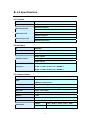
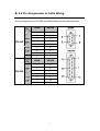
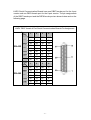
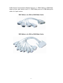
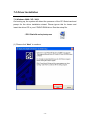
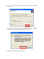
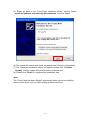
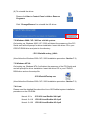
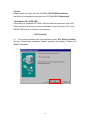
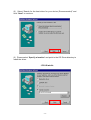
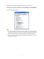
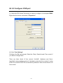
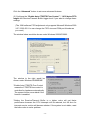
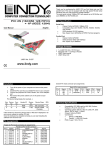
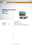
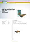
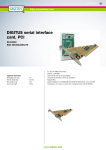
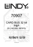
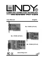
RS-422/485 PCI Card User Manual English No. 51200 (2 Port) No. 51202 (4 Port) No. 51204 (8 Port) www.lindy.com © LINDY ELECTRONICS LIMITED & LINDY-ELEKTRONIK GMBH - SECOND EDITION (Nov 2005) 1.0 Introduction Thank you for purchasing the LINDY RS-422/485 Controller. This PCI serial card enables your computer to support serial RS-422/485 ports with 128Kbyte FIFO, Auto Identify and Switch RS-422/485 and ARSC™ technology. 2.0 Packing List Please check if the following items are present and in good condition upon opening the packaging. Contact your vendor if any items are damaged or missing. 1. Hardware: Serial Communication Board: LINDY PCI Host Controller × 1 Cables: 4 Port, No.51202 : DB37 Male to 4 Port DB9 × 1 8 Port, No.51204 : DB78 Male to 8 Port DB9 × 1 2. Driver CD 3. This User Manual -1- 3.0 Features 1. 2. 3. Fully compliant with PCI Specification Version 2.2 Supports both 64 Bit & 32 Bit PCI Bus and 3.3V & 5V connector keys. High speed serial ports support baud rates of up to 921.6Kbps. 4. Provides a FIFO maximize size of 128Kbytes. The 128K FIFO can reduce CPU loading, improving system performance dramatically. 5. The unique Auto Switch RS-422/485 technology makes it easy and convenient to manage the device without the need for jumper or switch settings. ARSC™ (Auto RTS Signal Control) technology can identify the status of the data transceiver or receiver and send the RTS signal automatically, 6. 7. 8. 9. instead of using software to control the transmitter. High speed 16C650 compatible communication controller with SUN1889 single chip hardware flow control to guarantee no data loss LINDY industrial host controller series are certified by WHQL, CE, and FCC approval. Ready for the Intel® Itanium® and AMD® Athlon 64® 64-bit CPU on Microsoft Windows® XP 64-bit Edition Version 2003 and Windows® Server 2003 for 64-bit Itanium-based or Extended Systems. -2- 4.0 Specifications 4.1 Function Type LINDY Industrial Host Controller Mode of Operation Differential Bus Transceivers RS-422 Full-Duplex RS-485 Half-Duplex Drivers per Line RS-422 1 Driver RS-485 10 Drivers Receivers per Line RS-422 10 Receivers RS-485 32 Receivers 4.2 Hardware IC SUN1889 Controller UART (16C650 compatible) Bus Interface 64 Bit & 32 Bit PCI Bus, 3.3V & 5V connector keys 51200: 2 ports Number of Ports 51202: 4 ports 51204: 8 ports 51200: 2 x DB9 Male Connector 51202: 1 x DB37 Female to 4 x DB9/Male 51204: 1 x DB78 Female to 8 x DB9/Male 4.3 Communication IRQ & I/O address FIFO BIOS assigned 32 byte hardware FIFO 128Kbyte software FIFO RS-485 Signal Control ARSC™ technology Select RS-422/485 Auto Switch RS-422/485 technology Baud rate 75bps ~ 921.6 Kbps Data bit 4,5,6,7,8 Stop bit 1,1.5,2 Parity even, odd, none, mark, space Flow Control None, Xon/Xoff, Hardware Data Signal RS-422 TxD+/-, RxD+/-, RTS+/-, CTS+/-, GND RS-485 Data+/-, RTS+/-, CTS+/-, GND -3- 4.4 Driver support Driver Support Windows3.x/95/98SE/ME/NT/2000/XP/2003 DOS, OS/2 , Linux 2.0.x / 2.2.x / 2.4.18 / 2.4.20 4.5 Dimensions Dimensions (W × D) (Std.Bracket:121mm) 51200 120 × 80mm 51202 160 × 104mm 51204 180 × 108mm 4.6 Regulatory Approvals Regulatory Approvals Hardware CE, FCC Software WHQL 4.8 System Requirements 1. Pentium or equivalent computer with an available PCI slot. 2. CD-ROM / DVD-ROM required for software installation. 3. Windows 3.x/ 95/98SE/Me/NT/2000/XP/2003, DOS, Linux OS system 5.0 Operating Environment 1. Operating temperature: 0° ~ 57° 2. Operating humidity: 5 to 95% 3. Storage temperature:-20° ~ 85° -4- 6.0 Pin Assignments & Cable Wiring The pin assignments of the DB9 and DB25 Male port are stated as below: Type DB9M DB25M TxD- 1 8 TxD+ 2 3 RxD+ 3 2 RS-422 RxD- 4 20 RTS- 6 6 RTS+ 7 4 CTS+ 8 5 CTS- 9 22 GND 5 7 DB9M DB25M Data+ 2 3 Data- 1 8 RS-485 RTS- 6 6 RTS+ 7 4 CTS+ 8 5 CTS- 9 22 GND 5 7 Signal Type Signal -5- LINDY Serial Communication Boards have one DB37 female port for the 4 port version and one DB78 female port for the 8 port version. The pin assignments of the DB37 female port and the DB78 female port are shown below and on the following page. LINDY DB37 female 4 Port Serial Communication Boards Pin Assignment Port 1 2 3 4 TxD- 34 11 25 2 TxD+ 37 14 28 5 RxD+ 19 33 10 24 RS-422 RxD- 16 30 7 21 RTS- 17 31 8 22 RTS+ 18 32 9 23 CTS+ 36 13 27 4 CTS- 15 29 6 20 GND 35 12 26 3 1 2 3 4 Data+ 37 14 28 5 Data- 34 11 25 2 RS-485 RTS- 17 31 8 22 RTS+ 18 32 9 23 CTS+ 36 13 27 4 CTS- 15 29 6 20 GND 35 12 26 3 Signal Port Signal -6- LINDY DB78 female 8 Port Serial Communication Boards Pin Assignment Port 1 2 3 4 5 6 7 8 TxD- 21 6 30 15 60 45 69 54 TxD+ 1 25 10 34 40 64 49 73 RxD+ 2 26 11 35 41 65 50 74 RS-422 RxD- 22 7 31 16 61 46 70 55 3 27 12 36 42 66 51 75 RTS+ 24 9 33 18 63 48 72 57 CTS+ 4 28 13 37 43 67 52 76 CTS- 5 29 14 38 44 68 53 77 GND 23 8 32 17 62 47 71 56 1 2 3 4 5 6 7 8 1 25 10 34 40 64 49 73 Data- 21 6 30 15 60 45 69 54 3 27 12 36 42 66 51 75 RTS+ 24 9 33 18 63 48 72 57 CTS+ 4 28 13 37 43 67 52 76 CTS- 5 29 14 38 44 68 53 77 GND 23 8 32 17 62 47 71 56 Signal RTS- Port Signal Data+ RS-485 RTS- -7- LINDY Serial Communication Boards feature a 1 x DB37 Male to 4 DB9 Male cable for the 4 port version, and a 1 x DB78 Male port to 8 x DB9 Male ports cable, for 8 port version. DB37 Male to 4 x DB9 or DB25 Male Cable DB78 Male to 8 x DB9 or DB25 Male Cable -8- 6.1 Jumper Settings These cards feature built-in termination resistors for each serial port. You can modify the jumper settings (short the pins) to avoid impedance mismatch problems when operating under multi-drop transmission. When an electrical signal travels through two resistance junctions in a transmission line, the impedance mismatch will sometimes cause signal reflection. Signal reflection causes signal distortion, which in turn contributes to communication errors. The solution to this problem is to establish the same impedance at the line ends as in the line itself by terminating them with resistors. It is normally sufficient when the value of the termination resistors equals the characteristic impedance of the transmission line. LINDY RS-422/485 serial boards feature built-in termination resistors to prevent these problems. -9- 7.0 Driver Installation 7.1 Windows 2000 / XP / 2003: On booting up, the system will detect the presence of the PCI Serial card and prompt for the driver installation wizard. Please ignore this for known and insert the driver CD in your CD/DVD ROM drive. Run the setup file: : \PCI IO\win2k and xp\setup.exe (1) Please click “Next” to continue. - 10 - (2) You can select the folder location in which the driver is installed. Click Next” to continue. (3)The Software Installation Notice will appear, please click “Continue Anyway”, and the system will install the driver automatically. (4) Please click “Finish” and eject the driver CD. - 11 - (5) Please go back to the “Found New Hardware Wizard” window. Select “Install the software automatically (Recommend)” and click “Next”. (6) The system will search and install the appropriate I/O driver automatically. (7) The “Hardware Installation Notice” will appear, please click “Continue Anyway” and the system will install the driver automatically. (8) Please click “Finish” to complete this installation step. Note: The “Found New Hardware Wizard” windows will show up and re-install the driver several times until you finish setting up each serial port. - 12 - (9) To uninstall the driver: Please click Start > Control Panel > Add or Remove Programs Click “Change/Remove” to uninstall the I/O driver. 7.2 Windows 2000 / XP / 2003 on a 64-bit system: On booting up, Windows 2000 / XP / 2003 will detect the presence of the PCI Serial card and will prompt for driver installation. Insert the driver CD in your CD/DVD ROM drive and point to the directory: : \PCI IO\win2k and xp_64bit\ (Now follow the Windows 2000 / XP / 2003 installation procedure. Section 7.1) 7.3 Windows NT4.0: On booting up, Windows NT4.0 will detect the presence of the PCI Serial card and will prompt for driver installation. Insert the driver CD in your CD/DVD ROM drive and run the setup file: : \PCI IO\winNT\setup.exe (Now follow the Windows 2000 / XP / 2003 installation procedure. Section 7.1) 7.4 Linux: Please read the detailed files about the Linux OS RedHat system installation procedure on the CD ROM : Kernal: 2.2.x :\PCI IO\Linux\RedHat V6.0.pdf Kernal: 2.4.18 :\PCI IO\Linux\RedHat V8.0.pdf Kernal: 2.4.20 :\PCI IO\Linux\RedHat V9.0.pdf - 13 - 7.5 Dos: Please install the driver from the CD ROM: \PCI IO\DOS\install.exe, and follow the installation steps from the CD ROM: \PCI IO\serial.pdf 7.6 Windows 95 / 98SE / ME: On booting up, Windows 95 / 98SE / ME will detect the presence of the PCI Serial card and will prompt for driver installation. Insert the driver CD in your CD/DVD ROM drive and point to the directory: : \PCI IO\win9x\ (1) The system will detect the new hardware device “PCI Serial Controller” and the “Found New Hardware Wizard” windows will display. Please click “Next” to continue. - 14 - (2) Select “Search for the best driver for your device (Recommended)” and click “Next” to continue. (3) Please select “Specify a location” and point to the CD Driver directory to install the driver. : \PCI IO\win9x\ - 15 - (4) The system will search and install the appropriate IO driver automatically. Please click “Next” to continue. (5) Please click “Finish” to complete this installation step. Note: The “Add New Hardware Wizard” windows will display and install drivers several times until you finish setting up each serial port. 7.7 Verifying Serial PCI card installation: - 16 - When Windows has finished installing the driver you must check: Control Panel > System > Hardware > Device Manager >Ports[COM&LPT] It will show the additional ports: Note: 1. If you have installed PCI Serial ports in your system, you will be requested to restart your computer, when you have finished setting up each serial port. Click “Yes” if all serial ports have been installed, otherwise click “No”. 2. The item number you see during the installation may be different from the item you have installed. - 17 - 8.0 Configure COM port (1) Select the PCI Serial Port which you want to configure, for example COM3. Right click the mouse, and select “Properties”. (2) Click “Port Settings”. Configure the Bits per second, Data bits, Parity, Stop bits and Flow control if you want to change them. There are three kinds of flow control: Xon/Xoff, Hardware and None. Xon/Xoff is using software protocol. Hardware means the flow control is using RTS/CTS, but the RTS/CTS is controlled by software. None means there is no flow control. - 18 - Click the “Advanced” button to set more advanced features. (3) Configure the “Enable Auto CTS/RTS Flow Control ”,“ 16/32 bytes FIFO length and Receive/Transmit Buffer trigger level if you want to change these settings (The 128K software FIFO adjustment only supports Microsoft Windows 2000 / XP / 2003 OS. You can change the FIFO size and COM port Number as you need.) The window below would be shown under Windows 2000/XP/2003. The window to the right would be shown under Windows 95/98SE/ME. *Enable Auto CTS/RTS Flow Control means the CTS/RTS flow control is controlled by hardware automatically. The system will be more stable if the function is enabled. *Setting the Receive/Transmit Buffer to a higher value will get faster performance because the CPU interrupts will be reduced, but the time for interrupt service routine will become shorter. If the system is not stable, reset the lower value to solve problem. - 19 - - 20 - This device complies with Part 15 of the FCC Rules. Operation is subject to the following two conditions: (1) this device may not cause harmful interference, and (2) this device must accept any interference received, including interference that may cause undesired operations. - 21 -