1
RETURN TO MAIN MENU
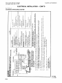
IM305-C
NA-5 AUTOMATIC WELDING SYSTEM
September, 2010
For use with Models NA-5N
NA-5N
NA-5NF
NA-5S
NA-5SF
Safety Depends on You
Lincoln arc welding and cutting
equipment is designed and built
with safety in mind. However,
your overall safety can be
increased by proper installation
... and thoughtful operation on
your part. DO NOT INSTALL
OPERATE OR REPAIR THIS
EQUIPMENT WITHOUT READING THIS MANUAL AND THE
SAFETY PRECAUTIONS CONTAINED THROUGHOUT. And,
most importantly, think before
you act and be careful.
Damage Claims
When this equipment is shipped,
title passes to the purchaser
upon receipt by the carrier.
Consequently, claims for material damaged in shipment must be
made by the purchaser against
the transportation company at
the time the shipment is
received.
OPERATOR’S MANUAL
Copyright © Lincoln Global Inc.
• World's Leader in Welding and Cutting Products •
• Sales and Service through Subsidiaries and Distributors Worldwide •
Cleveland, Ohio 44117-1199 U.S.A. TEL: 216.481.8100 FAX: 216.486.1751 WEB SITE: www.lincolnelectric.com
i
i
SAFETY
WARNING
CALIFORNIA PROPOSITION 65 WARNINGS
Diesel engine exhaust and some of its constituents
are known to the State of California to cause cancer, birth defects, and other reproductive harm.
The Above For Diesel Engines
The engine exhaust from this product contains
chemicals known to the State of California to cause
cancer, birth defects, or other reproductive harm.
The Above For Gasoline Engines
ARC WELDING CAN bE HAzARDOUS. PROTECT YOURSELF AND OTHERS FROM POSSIbLE SERIOUS INJURY OR DEATH.
KEEP CHILDREN AWAY. PACEMAKER WEARERS SHOULD CONSULT WITH THEIR DOCTOR bEFORE OPERATING.
Read and understand the following safety highlights. For additional safety information, it is strongly recommended that you
purchase a copy of “Safety in Welding & Cutting - ANSI Standard Z49.1” from the American Welding Society, P.O. Box
351040, Miami, Florida 33135 or CSA Standard W117.2-1974. A Free copy of “Arc Welding Safety” booklet E205 is available
from the Lincoln Electric Company, 22801 St. Clair Avenue, Cleveland, Ohio 44117-1199.
bE SURE THAT ALL INSTALLATION, OPERATION, MAINTENANCE AND REPAIR PROCEDURES ARE
PERFORMED ONLY bY QUALIFIED INDIVIDUALS.
FOR ENGINE
powered equipment.
1.h. To avoid scalding, do not remove the
radiator pressure cap when the engine is
hot.
1.a. Turn the engine off before troubleshooting and maintenance
work unless the maintenance work requires it to be running.
____________________________________________________
1.b. Operate engines in open, well-ventilated
areas or vent the engine exhaust fumes
outdoors.
____________________________________________________
1.c. Do not add the fuel near an open flame
welding arc or when the engine is running.
Stop the engine and allow it to cool before
refueling to prevent spilled fuel from vaporizing on contact with hot engine parts and
igniting. Do not spill fuel when filling tank. If
fuel is spilled, wipe it up and do not start
engine until fumes have been eliminated.
____________________________________________________
1.d. Keep all equipment safety guards, covers and devices in
position and in good repair.Keep hands, hair, clothing and
tools away from V-belts, gears, fans and all other moving
parts when starting, operating or repairing equipment.
____________________________________________________
1.e. In some cases it may be necessary to remove safety
guards to perform required maintenance. Remove
guards only when necessary and replace them when the
maintenance requiring their removal is complete.
Always use the greatest care when working near moving
parts.
___________________________________________________
1.f. Do not put your hands near the engine fan.
Do not attempt to override the governor or
idler by pushing on the throttle control rods
while the engine is running.
___________________________________________________
1.g. To prevent accidentally starting gasoline engines while
turning the engine or welding generator during maintenance
work, disconnect the spark plug wires, distributor cap or
magneto wire as appropriate.
ELECTRIC AND
MAGNETIC FIELDS
may be dangerous
2.a. Electric current flowing through any conductor causes
localized Electric and Magnetic Fields (EMF). Welding
current creates EMF fields around welding cables and
welding machines
2.b. EMF fields may interfere with some pacemakers, and
welders having a pacemaker should consult their physician
before welding.
2.c. Exposure to EMF fields in welding may have other health
effects which are now not known.
2.d. All welders should use the following procedures in order to
minimize exposure to EMF fields from the welding circuit:
2.d.1. Route the electrode and work cables together - Secure
them with tape when possible.
2.d.2. Never coil the electrode lead around your body.
2.d.3. Do not place your body between the electrode and
work cables. If the electrode cable is on your right
side, the work cable should also be on your right side.
2.d.4. Connect the work cable to the workpiece as close as
possible to the area being welded.
2.d.5. Do not work next to welding power source.
Mar ‘95
ii
ii
SAFETY
ELECTRIC SHOCK can
kill.
3.a. The electrode and work (or ground) circuits
are electrically “hot” when the welder is on.
Do not touch these “hot” parts with your bare
skin or wet clothing. Wear dry, hole-free
gloves to insulate hands.
3.b. Insulate yourself from work and ground using dry insulation.
Make certain the insulation is large enough to cover your full
area of physical contact with work and ground.
In addition to the normal safety precautions, if welding
must be performed under electrically hazardous
conditions (in damp locations or while wearing wet
clothing; on metal structures such as floors, gratings or
scaffolds; when in cramped positions such as sitting,
kneeling or lying, if there is a high risk of unavoidable or
accidental contact with the workpiece or ground) use
the following equipment:
• Semiautomatic DC Constant Voltage (Wire) Welder.
• DC Manual (Stick) Welder.
• AC Welder with Reduced Voltage Control.
3.c. In semiautomatic or automatic wire welding, the electrode,
electrode reel, welding head, nozzle or semiautomatic
welding gun are also electrically “hot”.
3.d. Always be sure the work cable makes a good electrical
connection with the metal being welded. The connection
should be as close as possible to the area being welded.
3.e. Ground the work or metal to be welded to a good electrical
(earth) ground.
3.f. Maintain the electrode holder, work clamp, welding cable and
welding machine in good, safe operating condition. Replace
damaged insulation.
3.g. Never dip the electrode in water for cooling.
3.h. Never simultaneously touch electrically “hot” parts of
electrode holders connected to two welders because voltage
between the two can be the total of the open circuit voltage
of both welders.
3.i. When working above floor level, use a safety belt to protect
yourself from a fall should you get a shock.
ARC RAYS can burn.
4.a. Use a shield with the proper filter and cover
plates to protect your eyes from sparks and
the rays of the arc when welding or observing
open arc welding. Headshield and filter lens
should conform to ANSI Z87. I standards.
4.b. Use suitable clothing made from durable flame-resistant
material to protect your skin and that of your helpers from
the arc rays.
4.c. Protect other nearby personnel with suitable, non-flammable
screening and/or warn them not to watch the arc nor expose
themselves to the arc rays or to hot spatter or metal.
FUMES AND GASES
can be dangerous.
5.a. Welding may produce fumes and gases
hazardous to health. Avoid breathing these
fumes and gases. When welding, keep
your head out of the fume. Use enough
ventilation and/or exhaust at the arc to keep
fumes and gases away from the breathing zone. When
welding with electrodes which require special
ventilation such as stainless or hard facing (see
instructions on container or MSDS) or on lead or
cadmium plated steel and other metals or coatings
which produce highly toxic fumes, keep exposure as
low as possible and within applicable OSHA PEL and
ACGIH TLV limits using local exhaust or mechanical
ventilation. In confined spaces or in some circumstances, outdoors, a respirator may be required.
Additional precautions are also required when welding
on galvanized steel.
5. b. The operation of welding fume control equipment is affected
by various factors including proper use and positioning of
the equipment, maintenance of the equipment and the specific welding procedure and application involved. Worker
exposure level should be checked upon installation and
periodically thereafter to be certain it is within applicable
OSHA PEL and ACGIH TLV limits.
5.c. Do not weld in locations near chlorinated hydrocarbon vapors
coming from degreasing, cleaning or spraying operations.
The heat and rays of the arc can react with solvent vapors to
form phosgene, a highly toxic gas, and other irritating products.
3.j. Also see Items 6.c. and 8.
5.d. Shielding gases used for arc welding can displace air and
cause injury or death. Always use enough ventilation,
especially in confined areas, to insure breathing air is safe.
5.e. Read and understand the manufacturer’s instructions for this
equipment and the consumables to be used, including the
material safety data sheet (MSDS) and follow your
employer’s safety practices. MSDS forms are available from
your welding distributor or from the manufacturer.
5.f. Also see item 1.b.
iii
iii
SAFETY
WELDING and CUTTING
SPARKS can
cause fire or explosion.
6.a. Remove fire hazards from the welding area.
If this is not possible, cover them to prevent
the welding sparks from starting a fire.
Remember that welding sparks and hot
materials from welding can easily go through small cracks
and openings to adjacent areas. Avoid welding near
hydraulic lines. Have a fire extinguisher readily available.
6.b. Where compressed gases are to be used at the job site,
special precautions should be used to prevent hazardous
situations. Refer to “Safety in Welding and Cutting” (ANSI
Standard Z49.1) and the operating information for the
equipment being used.
6.c. When not welding, make certain no part of the electrode
circuit is touching the work or ground. Accidental contact
can cause overheating and create a fire hazard.
6.d. Do not heat, cut or weld tanks, drums or containers until the
proper steps have been taken to insure that such procedures
will not cause flammable or toxic vapors from substances
inside. They can cause an explosion even though they have
been “cleaned”. For information, purchase “Recommended
Safe Practices for the Preparation for Welding and Cutting of
Containers and Piping That Have Held Hazardous
Substances”, AWS F4.1 from the American Welding Society
(see address above).
6.e. Vent hollow castings or containers before heating, cutting or
welding. They may explode.
6.f. Sparks and spatter are thrown from the welding arc. Wear oil
free protective garments such as leather gloves, heavy shirt,
cuffless trousers, high shoes and a cap over your hair. Wear
ear plugs when welding out of position or in confined places.
Always wear safety glasses with side shields when in a
welding area.
6.g. Connect the work cable to the work as close to the welding
area as practical. Work cables connected to the building
framework or other locations away from the welding area
increase the possibility of the welding current passing
through lifting chains, crane cables or other alternate circuits. This can create fire hazards or overheat lifting chains
or cables until they fail.
6.h. Also see item 1.c.
CYLINDER may explode
if damaged.
7.a. Use only compressed gas cylinders
containing the correct shielding gas for the
process used and properly operating
regulators designed for the gas and
pressure used. All hoses, fittings, etc. should be suitable for
the application and maintained in good condition.
7.b. Always keep cylinders in an upright position securely
chained to an undercarriage or fixed support.
7.c. Cylinders should be located:
• Away from areas where they may be struck or subjected to
physical damage.
• A safe distance from arc welding or cutting operations and
any other source of heat, sparks, or flame.
7.d. Never allow the electrode, electrode holder or any other
electrically “hot” parts to touch a cylinder.
7.e. Keep your head and face away from the cylinder valve outlet
when opening the cylinder valve.
7.f. Valve protection caps should always be in place and hand
tight except when the cylinder is in use or connected for
use.
7.g. Read and follow the instructions on compressed gas
cylinders, associated equipment, and CGA publication P-l,
“Precautions for Safe Handling of Compressed Gases in
Cylinders,” available from the Compressed Gas Association
1235 Jefferson Davis Highway, Arlington, VA 22202.
FOR ELECTRICALLY
powered equipment.
8.a. Turn off input power using the disconnect
switch at the fuse box before working on
the equipment.
8.b. Install equipment in accordance with the U.S. National
Electrical Code, all local codes and the manufacturer’s
recommendations.
8.c. Ground the equipment in accordance with the U.S. National
Electrical Code and the manufacturer’s recommendations.
6.I. Read and follow NFPA 51B “ Standard for Fire Prevention
During Welding, Cutting and Other Hot Work”, available
from NFPA, 1 Batterymarch Park, PO box 9101, Quincy, Ma
022690-9101.
6.j. Do not use a welding power source for pipe thawing.
Refer to http://www.lincolnelectric.com/safety for additional safety information.
iv
SAFETY
PRÉCAUTIONS DE SÛRETÉ
Pour votre propre protection lire et observer toutes les instructions
et les précautions de sûreté specifiques qui parraissent dans ce
manuel aussi bien que les précautions de sûreté générales suivantes:
Sûreté Pour Soudage A L’Arc
1. Protegez-vous contre la secousse électrique:
a. Les circuits à l’électrode et à la piéce sont sous tension
quand la machine à souder est en marche. Eviter toujours
tout contact entre les parties sous tension et la peau nue
ou les vétements mouillés. Porter des gants secs et sans
trous pour isoler les mains.
b. Faire trés attention de bien s’isoler de la masse quand on
soude dans des endroits humides, ou sur un plancher
metallique ou des grilles metalliques, principalement dans
les positions assis ou couché pour lesquelles une grande
partie du corps peut être en contact avec la masse.
c. Maintenir le porte-électrode, la pince de masse, le câble
de soudage et la machine à souder en bon et sûr état
defonctionnement.
d.Ne jamais plonger le porte-électrode dans l’eau pour le
refroidir.
e. Ne jamais toucher simultanément les parties sous tension
des porte-électrodes connectés à deux machines à souder
parce que la tension entre les deux pinces peut être le
total de la tension à vide des deux machines.
f. Si on utilise la machine à souder comme une source de
courant pour soudage semi-automatique, ces precautions
pour le porte-électrode s’applicuent aussi au pistolet de
soudage.
2. Dans le cas de travail au dessus du niveau du sol, se protéger
contre les chutes dans le cas ou on recoit un choc. Ne jamais
enrouler le câble-électrode autour de n’importe quelle partie
du corps.
3. Un coup d’arc peut être plus sévère qu’un coup de soliel,
donc:
a. Utiliser un bon masque avec un verre filtrant approprié
ainsi qu’un verre blanc afin de se protéger les yeux du rayonnement de l’arc et des projections quand on soude ou
quand on regarde l’arc.
b. Porter des vêtements convenables afin de protéger la
peau de soudeur et des aides contre le rayonnement de
l‘arc.
c. Protéger l’autre personnel travaillant à proximité au
soudage à l’aide d’écrans appropriés et non-inflammables.
4. Des gouttes de laitier en fusion sont émises de l’arc de
soudage. Se protéger avec des vêtements de protection libres
de l’huile, tels que les gants en cuir, chemise épaisse, pantalons sans revers, et chaussures montantes.
iv
5. Toujours porter des lunettes de sécurité dans la zone de
soudage. Utiliser des lunettes avec écrans lateraux dans les
zones où l’on pique le laitier.
6. Eloigner les matériaux inflammables ou les recouvrir afin de
prévenir tout risque d’incendie dû aux étincelles.
7. Quand on ne soude pas, poser la pince à une endroit isolé de
la masse. Un court-circuit accidental peut provoquer un
échauffement et un risque d’incendie.
8. S’assurer que la masse est connectée le plus prés possible
de la zone de travail qu’il est pratique de le faire. Si on place
la masse sur la charpente de la construction ou d’autres
endroits éloignés de la zone de travail, on augmente le risque
de voir passer le courant de soudage par les chaines de levage, câbles de grue, ou autres circuits. Cela peut provoquer
des risques d’incendie ou d’echauffement des chaines et des
câbles jusqu’à ce qu’ils se rompent.
9. Assurer une ventilation suffisante dans la zone de soudage.
Ceci est particuliérement important pour le soudage de tôles
galvanisées plombées, ou cadmiées ou tout autre métal qui
produit des fumeés toxiques.
10. Ne pas souder en présence de vapeurs de chlore provenant
d’opérations de dégraissage, nettoyage ou pistolage. La
chaleur ou les rayons de l’arc peuvent réagir avec les vapeurs
du solvant pour produire du phosgéne (gas fortement toxique)
ou autres produits irritants.
11. Pour obtenir de plus amples renseignements sur la sûreté,
voir le code “Code for safety in welding and cutting” CSA
Standard W 117.2-1974.
PRÉCAUTIONS DE SÛRETÉ POUR
LES MACHINES À SOUDER À
TRANSFORMATEUR ET À
REDRESSEUR
1. Relier à la terre le chassis du poste conformement au code de
l’électricité et aux recommendations du fabricant. Le dispositif
de montage ou la piece à souder doit être branché à une
bonne mise à la terre.
2. Autant que possible, I’installation et l’entretien du poste seront
effectués par un électricien qualifié.
3. Avant de faires des travaux à l’interieur de poste, la debrancher à l’interrupteur à la boite de fusibles.
4. Garder tous les couvercles et dispositifs de sûreté à leur
place.
NOTES
EW2357-A
L 2.5.10-A
http://www.lincolnelectric.com/knowledge/articles/
content/steelhatconstruction.asp
EW2357-A
Sec. T2.5.7-A (Continued)
File as Sec. L2.5.10-A for IM278)
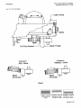
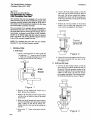
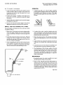
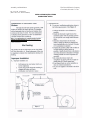
Hat
Insulated
friction free
eyelet
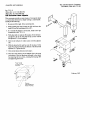
Speed Feed Drum
Turntable
http://www.lincolnelectric.com/knowledge/articles/
content/drumhandling.asp
http://www.lincolnelectric.com/knowledge/articles/
content/speedfeeddrums.asp
EW2357-B
Sec. T2.5.7-B (FOR IM305)
(File as Sec.L2.5.10-B for IM278)
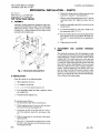
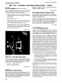
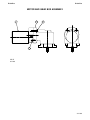
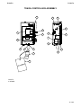
Assembly and Installation
Sec. T2.5.7-B (Continued)
(File as Sec. L2.5.10-B for IM278)
The Lincoln Electric Company
Cleveland, Ohio 44117-1199
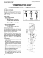
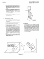
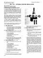
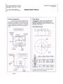
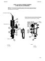
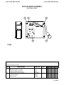
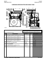
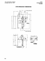
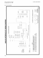
INSTALLATION INSTRUCTIONS
SPEED-FEED REELS
®
http://www.lincolnelectric.com/knowledge/articles/
content/speedfeeddrum.asp and view the Speed
P-135-A
P-135-A
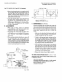
RETURN TO MAIN INDEX
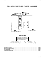
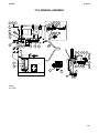
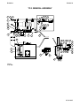
NA-5
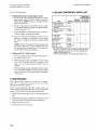
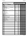
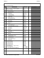
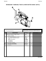
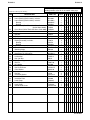
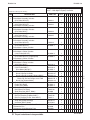
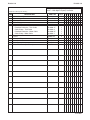
SEC. T 7.1 – PARTS LIST INDEX
.
#
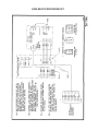
Wire Feed Gear Box . . . . . . . . . . . . . . . . . . . . . . . . . . . . . . . . . . . . . . . . . . . . . . . . . . . . . . . . . . P-100-C
Wire Feed Drive Roll Box (For Codes Below 8800 Only) . . . . . . . . . . . . . . . . . . . . . . . . . . . . . . . P-100-D
Wire Feed Drive Roll Box (For Codes Above 8800) . . . . . . . . . . . . . . . . . . . . . . . . . . . . . . . . . . . P-100-D.2
Head Mounting . . . . . . . . . . . . . . . . . . . . . . . . . . . . . . . . . . . . . . . . . . . . . . . . . . . . . . . . . . . . . . P-100-F
Wire Reel and Reel Mounting (NA-3, NA-4 and NA-5) . . . . . . . . . . . . . . . P-100-G (NA-3, NA-4 and NA-5)
Cable Assembly, Power Source to Controls . . . . . . . . . . . . . . . . . . . . . . . . . . . . . . . . . . . . . . . . . P-100-H
Flux Cored Wire Straightener (1/16”- 5/32”) . . . . . . . . . . . . . . . . . . . . . . . . . . . . . . . . . . . . . . . . . P-100-K
Cross Seam Adjuster . . . . . . . . . . . . . . . . . . . . . . . . . . . . . . . . . . . . . . . . . . . . . . . . . . . . . . . . . . P-100-L
Solid Wire Straightener (5/64”-7/32”) . . . . . . . . . . . . . . . . . . . . . . . . . . . . . . . . . . . . . . . . . . . . . . P-100-M
Flux Cored Wired Straightener, Twinarc . . . . . . . . . . . . . . . . . . . . . . . . . . . . . . . . . . . . . . . . . . . . P-100-N
K218 Horizontal Fillet/Lap Attachment . . . . . . . . . . . . . . . . . . . . . . . . . . . . . . . . . . . . . . . . . . . . . P-101-C
K233 (and K103) Contact Nozzle, K104 Linc-Fill Extension . . . . . . . . . . . . . . . . . . . . . . . . . . . . . P-101-D
K96 Horizontal Adjuster . . . . . . . . . . . . . . . . . . . . . . . . . . . . . . . . . . . . . . . . . . . . . . . . . . . . . . . . P-101-E
K233 Solenoid Assembly (NA-3, NA-4 and NA-5) . . . . . . . . . . . . . . . . . . . . . . . . . . . . . . . . . . . . P-101-F
K129 Submerged Arc Twinarc Kit . . . . . . . . . . . . . . . . . . . . . . . . . . . . . . . . . . . . . . . . . . . . . . . . P-101-G
K281 Wire Straightener for Tiny Twinarc . . . . . . . . . . . . . . . . . . . . . . . . . . . . . . . . . . . . . . . . . . . P-101-G.2
Flux Hopper . . . . . . . . . . . . . . . . . . . . . . . . . . . . . . . . . . . . . . . . . . . . . . . . . . . . . . . . . . . . . . . . P-101-H
K148 Contact, K149 Linc-Fill Extension . . . . . . . . . . . . . . . . . . . . . . . . . . . . . . . . . . . . . . . . . . . . P-101-K
K225 Submerged Arc Twinarc Kit . . . . . . . . . . . . . . . . . . . . . . . . . . . . . . . . . . . . . . . . . . . . . . . . P-101-L
K239 Innershield Twinarc Kit . . . . . . . . . . . . . . . . . . . . . . . . . . . . . . . . . . . . . . . . . . . . . . . . . . . . P-101-L.2
K231 (and K31) Contact Nozzle Assembly . . . . . . . . . . . . . . . . . . . . . . . . . . . . . . . . . . . . . . . . . . P-101-M
K226 (and K32) Contact Jaw Assembly . . . . . . . . . . . . . . . . . . . . . . . . . . . . . . . . . . . . . . . . . . . . P-101-N
Head Mounting and Lift Mechanism (For K23, K236, K247
and-HC, K325 and-HC) . . . . . . . . . . . . . . . . . . . . . . . . . . . . . . . . . . . . . . . . . . . . . . . . . . . . . . P-101-Q
K29 Vertical Head Lift Assembly (NA-1, 2, 3, 4 and 5 and LAF-3, 4 and 5) . . . . . . . . . . . . . . . . . . P-101-S
K238 High Frequency Unit . . . . . . . . . . . . . . . . . . . . . . . . . . . . . . . . . . . . . . . . . . . . . . . . . . . . . . P-101-T
K386 Narrow Gap Deep Grove Nozzle Assembly . . . . . . . . . . . . . . . . . . . . . . . . . . . . . . . . . . . . . P-101-U
K224 Solid-State Remote Field Control . . . . . . . . . . . . . . . . . . . . . . . . . . . . . . . . . . . . . . . . . . . . P-114-H
K285 Concentric Flux Cone . . . . . . . . . . . . . . . . . . . . . . . . . . . . . . . . . . . . . . . . . . . . . . . . . . . . . P-114-J
K278 Spreadarc, Complete Assembly . . . . . . . . . . . . . . . . . . . . . . . . . . . . . . . . . . . . . . . . . . . . . P-114-K
Spreadarc Carriage, Track and Drive Motor Assembly . . . . . . . . . . . . . . . . . . . . . . . . . . . . . . . P-114-L
Spreadarc Carriage Assembly . . . . . . . . . . . . . . . . . . . . . . . . . . . . . . . . . . . . . . . . . . . . . . . . . P-114-M
K237 Linc-Fill Starting Relay Assembly . . . . . . . . . . . . . . . . . . . . . . . . . . . . . . . . . . . . . . . . . . . . P-114-N
K325 (TC-3) Travel Carriage General Assembly . . . . . . . . . . . . . . . . . . . . . . . . . . . . . . . . . . . . . . P-132-C
Motor and Gear Box Assembly . . . . . . . . . . . . . . . . . . . . . . . . . . . . . . . . . . . . . . . . . . . . . . . . . P-132-D
Gear Box Assembly . . . . . . . . . . . . . . . . . . . . . . . . . . . . . . . . . . . . . . . . . . . . . . . . . . . . . . . . . P-132-E
Travel Control Box Assembly . . . . . . . . . . . . . . . . . . . . . . . . . . . . . . . . . . . . . . . . . . . . . . . . . . P-132-F
Wire Feed Drive Motor . . . . . . . . . . . . . . . . . . . . . . . . . . . . . . . . . . . . . . . . . . . . . . . . . . . . . . . . P-135-C
Control Box Assembly . . . . . . . . . . . . . . . . . . . . . . . . . . . . . . . . . . . . . . . . . . . . . . . . . . . . . . . . . P-135-D
Control Box Door Assembly . . . . . . . . . . . . . . . . . . . . . . . . . . . . . . . . . . . . . . . . . . . . . . . . . . . . . P-135-E
Control Box . . . . . . . . . . . . . . . . . . . . . . . . . . . . . . . . . . . . . . . . . . . . . . . . . . . . . . . . . . . . . . . . . P-135-F
K349 Multi-Procedure Kit . . . . . . . . . . . . . . . . . . . . . . . . . . . . . . . . . . . . . . . . . . . . . . . . . . . . . . . P-135-G
Pulsed Power Feeder Conversion Kit (Below Code 9100) . . . . . . . . . . . . . . . . . . . . . . . . . . . . . . Order K442-3
Pulsed Power Feeder Conversion Kit (Above Code 9100) . . . . . . . . . . . . . . . . . . . . . . . . . . . . . . Order K442-1
6-2-97
#
#
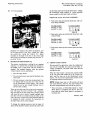
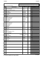
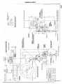
P-100-C
P-100-C
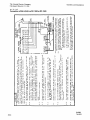
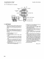
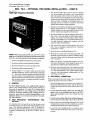
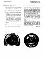
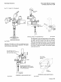
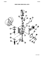
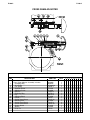
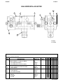
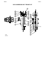
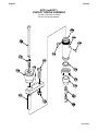
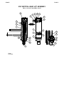
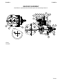
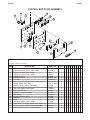
Part Numbers
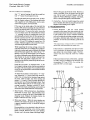
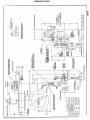
WIRE FEED GEAR BOX
Gear ratio is stenciled on the side of the gear case and on top of Item 12.
11
5
2
9
3
12
21
14
7
21
10
16
4
21
17
18
19
8
20
Part Numbers
1
15
6
13
Part Numbers
Part Numbers
# Indicates a Change This Printing
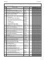
ITEM
DESCRIPTION
PART NO.
QTY.
1
2
3
4
5
6
6
7
8
9
10
11
12
12
12
13
14
15
16
17
18
19
20
20
21
21
Gear Box Asbly, (Includes Items 1-21) (95/1 Ratio):
Gear Box Asbly, (Includes Items 1-21) (55/1 or 57/1 Ratio):
Gear Box Asbly, (Includes Items 1-21) (142/1 Ratio):
Gear Box Case
Gear
Snap Ring
Woodruff Key
Snap Ring
Set Screw - New Design
Pipe Plug - Old Design
Bevel Shaft Assembly
Woodruff Key
Plain Washer
Spur Shaft Assembly
5/16-18 HN
Helical Gear (95/1 Ratio)
Helical Gear (55/1 or 57/1 Ratio)
Helical Gear (142/1 Ratio)
Socket Head Screw
Snap Ring
Gear Case Collar
Hollow Set Screw
Output Shaft Assembly
Drive Roll Spacer
Oil Seal
Gasket (.0125 Thick)
Gasket (.004 Thick)
Spacer Washer (.003 Thick)
Spacer Washer (.010 Thick)
L5199-3
L5199-2
L5199-1
G1328
S12504
S9776-23
#304
S9776-16
S11604-26
S10780-5 ø
S12511
#304
S9262-121
S12510
CF000029
S12503
S12881
S12882
T9447-28
S9776-23
M10256
S11604-13
S12509
T12146
S7611-15
T12119-1
T12119-2
S9262-110
S9262-111
1
1
1
1
1
1
1
1
2
2
1
1
1
1
1
1
1
1
6
1
1
1
1
1
1
ø
This part is obsolete and no longer available.
1 2 3 4 5 6 7 8 9
As Reqʼd
As Reqʼd
As Reqʼd
As Reqʼd
09-27-2007
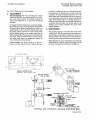
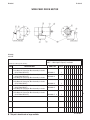
P-100-D
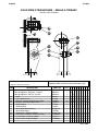
P-100-D
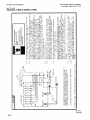
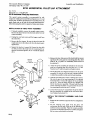
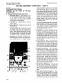
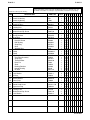
Part Numbers
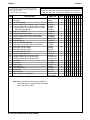
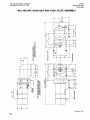
WIRE FEED DRIVE ROLL BOX
23
4
3
16
12
Part Numbers
5
2
17
18
10
Part Numbers
21
8
22
1
7
6
11
5
20
19
Part Numbers
14
15
09-27-2007
Sub Assembly Illustration
Sub Assembly Illustration
Sub Assembly Illustration
Sub Assembly Illustration
P-100-D.1
P-100-D.1
* For Twinarc (two electrodes fed through one head)
parts, see the appropriate Twinarc Assembly parts
list in the P-101 series.
# Indicates a Change This Printing
ITEM
1
2*
3*
3*
3*
4
5
6
6
7
8
10
10
11*
11*
11*
12
14
15*
15*
15*
16
17
18
19
20
21
22
23*
For 3/32 thru 7/32” wire, use the parts marked “X” in column 1.
For 1/16 thru 3/32” wire, use the parts marked “X” in column 2.
For .035 thru .052” wire, use the parts marked “X” in column 3.
1 2 3 4 5 6 7 8 9
DESCRIPTION
PART NO.
QTY.
Faceplate
Idle Roll Assembly
Incoming Guide Tube (3/32 thru 7/32”), Includes:
Incoming Guide Tube (1/16 thru 3/32”), Includes:
Incoming Guide Tube (.035 thru .052”), Includes:
.035-.045 Spring Guide
5/16-18 x .75 HHCS
Guide Tube Mounting Clip
Idle Roll Spring Screw, NA-2 Models Only
3/8-16 x 3 HHCS (NA-3, NA-4, & NA-5 Models)
Flat Washer
Idle Roll Spring
5/16-18 SQN (NA-2 Models)
Yoke Indicator Asbly (NA-3, NA-4 & NA-5 Models)
Drive Roll (3/32 thru 7/32”)
Drive Roll (1/16 thru 3/32”)
Drive Roll (.035 thru .052”)
Socket Head Cap Screw
Socket Head Cap Screw
Outgoing Guide Tube (3/32 thru 7/32”)
Outgoing Guide Tube (1/16 thru 3/32”)
Outgoing Guide Tube (.035 thru .052”)
Draw Bolt
1/4-20 HN
Stripper Bolt
Drive Roll Nut
Drive Roll Washer
Snap Ring
Drive Roll Key
Wire Straightener, Single Wire
L4052
S12475
S10168-4
S10168-2
S12857
T9367-4
CF000040
T8400
T10317-6
CF000039
S9262-120
T10247-7
CF000212
T13610
S12514
S12515
S12778
T9447-32
T9447-12
S10170-1
T13635-3/32
T13635-.052
T12090-1 ø
CF000017
T10317-7 ø
T10552
S9262-44
S11910-2
M8776-5
See P-100-K
or P-100-M
1
1
1
1
1
1
2
4
1
1
1
1
1
1
2
2
1
1
2
1
1
1
1
1
1
1
1
1
1
X
X
X
•
•
X
X
X
X
X
X
X
X
X
X
•
•
X
X
X
•
•
X
X
X
X
X
X
X
1
X X •
X
X
•
X
•
X
X
X
X
X
X
X
X
X
•
X
•
X
X
•
X
•
X
X
X
X
X
X
X
X
X
•
•
X
X
X
X
X
X
X
X
X
X
•
•
X
X
X
•
•
X
X
X
X
X
X
X
X
Note: When using K231 or K233 Contact Nozzle, a
long guide sleeve is required inside the Nozzle.
See P-101-M or P-101-D.
ø
This part is obsolete and no longer available.
09-27-2007
P-100-D.2
P-100-D.2
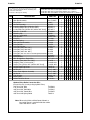
Part Numbers
WIRE FEED DRIVE ROLL BOX
(For Codes Above 8800)
23
4
3
16
12
Part Numbers
5
2
17
18
10
21
Part Numbers
8
7
6
11
5
14
Part Numbers
22
1
15
20
19
L6991
09-27-2007
Sub Assembly Illustration
Sub Assembly Illustration
Sub Assembly Illustration
Sub Assembly Illustration
P-100-D.3
P-100-D.3
* For Twinarc (two electrodes fed through one head)
parts, see the appropriate Twinarc Assembly parts
list in the P-101 series.
# Indicates a Change This Printing
ITEM
1
2
3*
4*
4*
4*
5
6
7
8
9
10
11
12
13
14*
14*
14*
14*
16
17
18
19*
19*
19*
20
21
24
28
29
35
36
37
For
For
For
For
3/32
1/16
.035
.045
thru
thru
thru
thru
DESCRIPTION
7/32”
3/32”
.052”
.052”
wire, use the parts marked “X” in column 1.
wire, use the parts marked “X” in column 2.
wire, use the parts marked “X” in column 3.
Cored Wire, use the parts marked “X” in column 4.
PART NO.
QTY.
Gear Box Assembly
Face Plate
Idle Roll Assembly
Incoming Guide Tube (3/32 thru 7/32”)
Incoming Guide Tube (1/16 thru 3/32”)
Incoming Guide Tube [.035 thru .052” (.045 thru .052” Cored)]
5/16-18 x .75 HHCS
Mounting Clip
3/16-16 x 3.00 HHCS
Plain Washer
Pivot Pin
Idle Roll Spring
Yoke Indicator Assembly
Drive Roll Nut
Drive Roll Washer
Drive Roll (3/32” thru 7/32”)
Drive Roll (1/16” thru 3/32”)
Drive Roll (.035” thru .052”)
Drive Roll (.045” thru .052” Cored Wire)(NA5,NA4,NA3)
Snap Ring
Drive Roll Key
Wire Straightener, Single Wire
Outgoing Tube (3/32” thru 7/32”)
Outgoing Tube (1/16 thru 3/32”)
Outgoing Tube [.035 thru .052” (.045 thru .052” Cored)]
Socket Head Cap Screw
Socket Head Cap Screw
24 Thru 27
Cross Seam Adjuster Assembly
29 thru 34
Plain Washer
Locking Key
Hollow Head Set Screw
See P-100-C
L6987
S12475
KP2116-2
KP2116-1
KP1967-1
CF000040
T8400
CF000039
S9262-120
T12206-1
T10247-7
T13610
T10552
S9262-44
S12514
S12515
S12778
S19113
S11910-2
M8776-5
See P-100-K or -M
S10170-1
T13635-3/32
T13635-.052
T9447-12
T9447-32
See P-100-F
See P-100-L
See P-100-F
S9262-131
T14896
S11604-8
1
1
1
1
1
1
2
4
1
1
1
1
1
1
1
2
2
1
2
1
1
1
1
1
1
2
1
Optional Drive Roller Conversion Kits:
(Includes Drive Roll, Incoming & Outgoing Guide Tubes)
3/32” thru 7/32” Wire
1/16” thru 3/32” Wire
.035” thru .052” Solid Wire
.045” thru .052” Cored Wire
.035” thru .045 Spring Guide
T13724-A
T13724-B
T13724-C
T13724-D
T9367-4
1
1
1
1
1 2 3 4 5 6 7 8 9
X
X
X
X
•
•
X
X
X
X
X
X
X
X
X
X
•
•
•
X
X
X
X
•
•
X
X
X
X
X
X
X
X
X
X
X
•
X
•
X
X
X
X
X
X
X
X
X
•
X
•
•
X
X
X
•
X
•
X
X
X
X
X
X
X
X
X
X
X
•
•
X
X
X
X
X
X
X
X
X
X
•
•
X
•
X
X
•
•
•
X
X
X
X
X
X
X
X
X
X
X
X
•
•
X
X
X
X
X
X
X
X
X
X
•
•
•
X
X
X
•
•
•
X
X
X
X
X
X
X
X
X
Note: When using K231 or K233 Contact Nozzle, a
long guide sleeve is required inside the nozzle.
See P-202-M or P-101-D.
09-27-2007
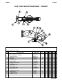
Part Numbers
P-100-F
P-100-F
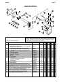
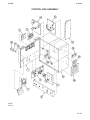
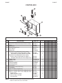
HEAD MOUNTING
71
77
85
68
86
70
84
69
Part Numbers
72
88
73
87
75
76
43
81
83
ITEM
43
Part Numbers
80
74
# Indicates a Change This Printing
Part Numbers
82
89
68
69
70
71
72
73
74
75
76
77
80
81
82
83
84
85
85
86
87
88
89
For standard NA-2, NA-3N, NA-3S, NA-4, NA-5N and NA-5S, use parts marked “X”
in column 1. For NA-2, NA-3N, NA-3S, NA-4, NA-5N and NA-5S with high frequency, use parts marked “X” in column 2. For NA-3F, NA-2FV, NA-3NF, NA-3SF, NA5NF and NA-5SF, use parts marked “X” in column 3.
DESCRIPTION
Head Support
Mounting Bracket (Not Used on Tractor Models)
Includes Items 68 thru 77
Welding Head Support Bracket, Includes:
Draw Bolt (Head Support to Mtg Bracket)
3/4-10 HN (Head Support to Mtg Bracket)
Insulation
Insulation Bushing
Insulation Washer
1/2-13 x 1.75 HHCS
Washer
Lock Washer
1/2-13 HN
Insulation Asbly, High Frequency
1/2-13 x 1.25 HHCS
Lock Washer
Clamping Bracket
Clamping Band
3/8-16 x .75 HHCS (Clamp to Gear Case)
Socket Head Cap Screw (Clamp to Gear Case)
Pivot Block
3/8-16 x 1.50 SHCS (Block to Clamping Brkt) (Except NA-5N & S)
3/8-16 x 2.75 (Block to Clamping Brkt) (NA-5N & S Only)
Roll Pin (Pivot Block to Head Support)
Draw Bolt (Pivot Block to Head Support)
3/4-10 HN (Pivot Block to Head Support)
Spacer (NA-5N & NA-5S Only)
PART NO.
QTY.
1 2 3 4 5 6 7 8 9
M8232
M6769
1
1
X X •
X • •
M4016
T4893
CF000025
S4322
T7305-18
S10773-9
CF000277
S9262-1
E106A-5
CF000027
S11771-1
CF000030
E106A-5
M10213
S12472
CF000034
T9447-18
M10215
T9447-18
T9447-31
T9967-29
T4893-3
CF000025
S10262-6
1
1
1
1
4
4
4
4
4
4
1
4
8
1
1
1
1
1
4
4
1
1
1
4
X
X
X
X
X
X
X
X
X
X
•
•
•
X
X
X
X
X
X
X
X
X
X
X
X
X
X
•
•
•
•
•
•
X
X
X
X
X
X
X
X
X
X
X
X
X
X
X
•
•
•
•
•
•
•
•
•
•
•
•
•
X
X
X
X
•
•
•
•
•
•
•
09-27-2007
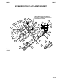
P-100-G (NA-3, NA-4 and NA-5)
P-100-G (NA-3, NA-4 and NA-5)
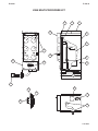
Part Numbers
WIRE REEL AND REEL MOUNTING
(NA-3N, NA-3S, NA-4, NA-5N and NA-5S)
2
4
3
6
Part Numbers
1
7
Support
Bracket
8
5
# Indicates a Change This Printing
Part Numbers
ITEM
1
2
3
4
5
Part Numbers
6
7
8
DESCRIPTION
Wire Reel Shaft Asbly, Includes:
1/2-13 x 1.00 HHCS
Lock Washer
Plain Washer
Plain Washer
Brake Assembly, Includes:
Brake Shoe
Wire Reel Shaft
Roll Pin
Pull Knob
Following Parts Not Illustrated
Wire Reel
U-Shaped Shaft Mounting Bracket
Following Parts Mount M12907 - No High Frequency
Flat Insulation
Insulation Tube
Insulation Washer
1/2-13 x 1.75 HHCS
1/2-13 HN
Following Parts Mount M12907 w/High Freq Insulation
Insulation Asbly
1/2-13 x 1.00 HHCS (Insulation to M12907)
1/2-13 HN
PART NO.
QTY.
M12908
CF000276
E106A-5
S9262-14
S9262-119
S14882
T13519
S15492
T9967-9
S11038
1
1
1
1
1
1
1
1
1
1
L4604
M12907
1
1
T8477-20
T12478-6
S10773-9
CF000277
CF000027
1
2
2
2
2
S11771-2
CF000276
CF000027
1
4
4
1 2 3 4 5 6 7 8 9
09-27-2007
P-100-H.a
P-100-H.a
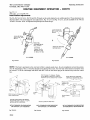
CABLE ASSEMBLIES – POWER SOURCE TO CONTROLS &
CONTROLS TO HEAD
# Indicates a Change This Printing
ITEM
DESCRIPTION
NA-2, NA-2F & NA-2FV
Cable Assembly (Power Source to Controls), Includes:
Multi-Conductor Control Cable
Electrode Cable
Cable Assembly (Controls to Head), Includes:
Electrode Cable (63 inches long)
NA-3 (ALL MODELS), NA-4 (w/CURRENT CONTROL RHEOSTAT)
AND NA-5 (ALL MODELS EXCEPT -R)
Cable Assembly (Power Source to Controls), Includes:
Multi-Conductor Control Cable, Includes:
Polarized Socket Connector
Connector Clamp
Electrode Cable
Cable Asbly (Controls to Head) (NA-3N, -NF, & -SF), Includes:
Multi-Conductor Control Cable (Motor), Includes:
Polarized Pin Connector
Polarized Receptacle Connector
Cable Clamp
Electrode Cable
Cable Asbly (Controls to Head) (NA-3S & NA-4), Includes:
Multi-Conductor Control Cable (Flux Valve), Includes:
Polarized Pin Connector
Polarized Receptacle Connector
Cable Clamp
Multi-Conductor Control Cable (Motor) Includes:
Polarized Pin Connector
Polarized Receptacle Connector
Cable Clamp
Electrode Cable
Cable Asbly (Controls to Head) (NA-5N, NF, & SF), Includes:
Multi-Conductor Control Cable (Motor), Includes:
Polarized Pin Connector
Polarized Receptacle Connector
Cable Clamp
Multi-Conductor Shielded Cable (Tach) Includes:
Polarized Pin Connector
Polarized Receptacle Connector
Cable Clamp
Electrode Cable
Cable Asbly (Controls to Head) (NA-5S) Includes:
Multi-Conductor Control Cable (Flux), Includes:
Polarized Pin Connector
Polarized Receptacle Connector
Cable Clamp
Multi-Conductor Control Cable (Motor), Includes:
Polarized Pin Connector
Polarized Receptacle Connector
ø
This part is obsolete and no longer available.
PART NO.
K97*
L4112-1*
L4112-2*
QTY.
L2286-191
1
1
1
1
2
K215*
L5267-B*
S12020-8
S12024-2
L5267-C *
K234*
L5318-D*
S12020-15
S12023-9
S12024-4
L5118-E*
K235*
L5318-B* ø
S12020-16
S12023-8
S12024-4
L5318-D*
S12020-15
S12023-9
S12024-4
L5318-E*
K338*
L6211-D*
S12020-27
S12023-12
S12024-1
L6211-F*
S12020-17
S12023-10
S12024-4
L6211-G*
K335
L6211-B*
S12020-16
S12023-8
S12024-4
L6211-D*
S12020-27
S12023-12
1
1
1
1
1
1
1
1
1
2
2
1
1
1
1
2
1
1
1
2
2
1
1
1
1
2
1
1
1
2
2
1
1
1
1
2
1
1
1
1 2 3 4 5 6 7 8 9
09-27-2007
P-100-H.b
P-100-H.b
CABLE ASSEMBLIES – POWER SOURCE TO CONTROLS &
CONTROLS TO HEAD
# Indicates a Change This Printing
ITEM
DESCRIPTION
Cable Clamp
Multi-Conductor Shielded Cable (Tach) Includes:
Polarized Pin Connector
Polarized Receptacle Connector
Cable Clamp
Electrode Cable
NA-4 (WITH CURRENT CONTROL SWITCH)
Cable Assembly (Power Source to Controls), Includes:
Multi-Conductor Control Cable, Includes:
Polarized Socket Connector
Connector Clamp
Electrode Cable
Cable Assembly (Controls to Head), Includes:
For K235 Parts Break-Down see P-100-H.a
NA-5R
Cable Assembly (Power Source to Controls) Includes:
Multi-Conductor Control Cable, Includes:
Polarized Socket Connector
Connector Clamp
Electrode Cable
Cable Assembly (Controls to Head), Includes:
For K338 Parts Break-Down see P-100-H.a
PART NO.
QTY.
S12024-1
L6211-F*
S12020-17
S12023-10
S12024-4
L6211-G*
2
1
1
1
2
2
K216*
L5231-B*
S12020-9
S12024-2
L5231-C*
K235*
1
1
1
1
1
1
K374*
L5267-B*
S12020-8
S12024-2
L5267-C*
K338
1
1
1
1
1
1
1 2 3 4 5 6 7 8 9
* Specify Length
09-27-2007
P-100-K
P-100-K
Part Numbers
FLUX-CORED WIRE STRAIGHTENER – SINGLE ARC
1/16” thru 5/32” Electrodes
6
2
3
4
1
5
Part Numbers
7
8
9
10
11
12
7
Part Numbers
Part Numbers
14
# Indicates a Change This Printing
ITEM
1
2
3
4
5
6
7
8
9
10
11
12
13
14
DESCRIPTION
Wire Straightener, Includes:
Body Assembly
Bearing
Washer
Lock Washer
5/16-18 HN
Socket Head Screw
Rollpin
Connecting Link
Wire Guide
#8-32 x .50 RHS
Retainer Plate
Wire Guide
Adjusting Knob
Adjusting Screw
PART NO.
M10214
M10311
M9300-55
S9262-140
E106A-3
CF000029
T9447-13
T9967-30
T12141
S12551
CF000033
T12145
T12126
S12547
T12102
QTY.
1 2 3 4 5 6 7 8 9
1
1
2
1
1
1
1
2
1
1
1
1
1
1
1
09-27-2007
P-100-L
P-100-L
Part Numbers
CROSS SEAM ADJUSTER
12
14
13
FACE
ACE PLATE
PL TE
15
Part Numbers
4
5
6
7
8
9
10
3
2
16
1
17
11
Part Numbers
ITEM
Part Numbers
FACE
ACE PLATE
PL TE
1
2
3
4
5
6
7
8
9
10
11
12
13
14
15
16
17
# Indicates a Change This Printing
DESCRIPTION
Cross Seam Adjuster Assembly, Includes:
Clamping Ring
#10-24 HN
Flat Spring
Shoulder Screw
Adjusting Screw
Roll Pin
Retaining Ring
Key
Adjusting Block
Handle
Socket Head Screw
Mounting Arm
Socket Head Screw
Socket Head Screw
Spatter Guard
Sleeve
Drive Pin
PART NO.
M10802
M10787
CF000010
T8701-1
T12535
S13202
T9967-8
S9776-3
M8776-6
S13203
T8312
T9447-18
S13204
T9447-9
T9447-10
S13233
T12537
T8433
QTY.
1 2 3 4 5 6 7 8 9
1
1
1
1
1
1
1
1
1
1
1
1
1
2
2
1
1
1
09-27-2007
P-100-M
P-100-M
Part Numbers
SOLID WIRE STRAIGHTENER – SINGLE & TWINARC
5/64 thru 7/32” Electrodes
27
25
26
28
Part Numbers
30
29
32
31
33
Part Numbers
24
# Indicates a Change This Printing
Part Numbers
ITEM
24
25
26
27
28
28
29
29
30
31
32
33
DESCRIPTION
Wire Straightener, Single Arc, Includes:
Wire Straightener, Twinarc, Includes:
Body
Cross Slide Screw
Bushing - Locates Slide Screw in Body
Roll Pin - Bushing to Slide Screw
Slide Bushing
Slide Bushing
Wire Guide Wheel Bearing
Wire Guide Wheel
Plainwasher - Bearing to Body
5/16-18 x 1.25 HHCS - Bearing to Body
Lock Washer - Bearing to Body
5/16-18 HN - Bearing to Body
Use only the parts marked “X” in the column under the
heading number called for in the model index page.
PART NO.
M8269-1
M8269-2
M8268
S10159
T10585
T9967-5
T10584
T10587
M9300-55
T10592-1
S9262-140
CF000028
E106A-3
CF000029
QTY.
1
1
1
1
1
1
1
1
2
1
2
1
1
1
1 2 3 4 5 6 7 8 9
X
•
X
X
X
X
X
•
X
•
X
X
X
X
•
X
X
X
X
X
•
X
•
X
X
X
X
X
09-27-2007
P-100-N
P-100-N
Part Numbers
FLUX CORED WIRE STRAIGHTENER – TWINARC
3
1
2
6
4
5
Part Numbers
7
8
9
15
10
11
7
Part Numbers
Part Numbers
14
12
13
# Indicates a Change This Printing
ITEM
1
2
3
4
5
6
7
8
9
10
11
12
13
14
15
DESCRIPTION
Wire Straightener, Includes:
Body Assembly
Bearing
Roll Pin
Lock Washer
5/16-18 HN
Socket Head Screw
Roll Pin
Connecting Link
Wire Guide
#8-32 x .50 RHS
Retainer Plate
Ingoing Wire Guide
Wing Screw
Adjusting Knob
Adjusting Screw
PART NO.
M12470
M10311-1
M9300-55
T9967-3
E106A-3
CF000029
T9447-20
T9967-30
T12141
M12469
CF000033
T12145
S14888
T9078
S12547
T12102
QTY.
1 2 3 4 5 6 7 8 9
1
1
2
1
3
1
1
2
1
1
1
1
1
1
1
1
09-27-2007
P-101-C.a
P-101-C.a
Part Numbers
K218 HORIZONTAL FILLET/LAP ATTACHMENT
35
38
NOTE: CONTACTS MUST BE ALIGNED SO
THAT WITH A 7/32 WIRE IN PLACE THE WIRE IS
CENTERED IN THE CHANNEL
34
33
37
39
47
36
1
32
40
41
5
3
30
31
42
Part Numbers
2
29
28
27
25
26
12
6
4
46
10
7
11
24
43
8
23
21
9
22
44
45
20
19
13
17
17
14
16
18
15
L5313
6-12-81U
Part Numbers
Part Numbers
18
10-3-84
Sub Assembly Illustration
Sub Assembly Illustration
Sub Assembly Illustration
Sub Assembly Illustration
P-101-C.b
P-101-C.b
# Indicates a Change This Printing
ITEM
1
2
3
4
5
6
7
8
9
10
11
12
13
14
15
16
17
17
18
18
19
20
21
22
23
24
25
26
27
28
29
30
31
32
33
34
35
36
37
38
39
40
41
42
43
44
45
46
47
ø
DESCRIPTION
PART NO.
QTY.
Socket Head Screw
Flat Washer
Insulating Washer
Insulating Bushing
Nose Adapter
Adapter Insulation
Hex Jam Nut
Hex Head Cap Screw
Spring
Pivot Assembly
Lead Block
Connection
Hex Head Screw
Hex Head Cap Screw
Hex Head Cap Screw
Hex Jam Nut
Hex Head Screw - Fillet Attachment
Hex Head Screw - Lap Attachment
Roller Bracket Assembly - Fillet Attachment
Roller Bracket Assembly - Lap Attachment
Hex Jam Nut
Wire Guide Spring
Hex Head Cap Screw
Flat Washer
Hex Jam Nut
Hex Jam Nut
Hex Head Cap Screw
Thread Cutting Screw
Insulation Bushing
Lockwasher
Flat Washer
Spring Insulation
Hex Jam Nut
Cover Plate
Insulating Bushing
Insulating Washer
Socket Head Screw
Flat Washer
Spacer
Hex Head Cap Screw
Lead
Insulation
Roll Support
Hex Head Cap Screw
Wire Contact Block
Leaf Spring
Wire Contact Block
Grease Fitting
Hex Head Screw
T9447-10
S9262-23
S10773-12
T8390
M12478
T8391
5/16-18
5/16-18 x 1.00
T8528
M8592
S7273
T8573 ø
3/8-16 x 1.00
1/2-13 x 1.75
3/8-16 x 1.00
5/16-18
5/16-18 x 1.00
T9694-8
S16749 ø
S7398 ø
3/8-16
S7664
3/8-16 x 1.25
S9262-4
3/8-16
1/2-13
1/2-13 x 1.00
S9225-17
T8725
E106A-2
S9262-23
T8724
1/2-13
T8404
T7028-23
S10773-41
T9447-11
S9262-30
T8752
3/8-16 x 1.50
S7266
S7387
S7386 ø
1/2-13 x 1.25
S16640-2
T8435
S16640-1
T11683-1 ø
5/16-18 x .75
4
4
8
4
1
1
1
1
1
1
1
1
2
2
1
1
1
1
1
1
1
1
2
4
4
1
1
2
2
2
2
2
2
1
2
2
2
2
1
2
1
1
1
1
1
1
1
2
2
Items Not Illustrated:
Flux Tube
Flux Control
Head Pivot
S10490
M8765
M12595
1
1
1
This part is obsolete and no longer available.
1 2 3 4 5 6 7 8 9
#
#
#
#
10-07-2002
Part Numbers
P-101-D.a
P-101-D.a
K233 (and K103) CONTACT NOZZLE
K104 LINC-FILL EXTENSION
NOTE A: The K103 nozzle for the NA2 is identical to the K233 except for Item A (nozzle insert). For the NA2 use both the appropriate Item A and the appropriate outgoing
guide tube (Item 15 of P-100-D).
(PART OF HEAD ASSEMBLY.)
NOTE A: The K103 nozzle for the NA2 is identical to the K233 except
for item A (nozzle insert). For the NA2 use both the appropriate Item A
and the appropriate outgoing guide tube (Item 15 of P-100-D).
Part Numbers
1
2
4
NOZZLE INSERT (A)
3
2
NOZZLE
ASSEMBLY
1
5
4
6
11
3
5
10
6
9
9
10
Part Numbers
7
7
NOZZLE TIP
8
8
K104
S12776
5-27-66C
Part Numbers
M12736
1-11-74B
5-80
P-101-D.b
# Indicates a Change This Printing
ITEM
DESCRIPTION
Nozzle Assembly, Includes:
Nozzle Insert, .035 - .052 Electrode
Nozzle Insert, 1/16, 5/64 and 3/32 Electrode
Nozzle Insulator
Socket Head Screw
Hex Head Screw
Hex Nut
Nozzle Body
Socket Head Cap Screw
Pressure Spring Assembly
Contact Pressure Shoe
Socket Head Cap Screw
Spring Bracket Assembly
Retaining Spring
A
A
1
2
3
4
5
6
7
8
9
10
11
12
12
12
12 F
12
12
Nozzle Tip
Nozzle Tip
Nozzle Tip
Nozzle Tip
Nozzle Tip
Nozzle Tip
1
2
3
4
5
6
7
8
8
8
8
8
9
10
Extension Assembly, Includes All Below
Insulating Plate
Insulating Bushing
Insulating Washer
Flat Washer
Lockwasher
Socket Head Cap Screw
Extension Guide Arm
Wire Guide - 3/32 Electrode
Wire Guide - 5/64 Electrode
Wire Guide - 1/16 Electrode
Wire Guide - .045 Electrode
Wire Guide - .035 Electrode
Hex Head Cap Screw
Flat Washer
ø
This part is obsolete and no longer available.
Sub Assembly Illustration
Sub Assembly Illustration
Sub Assembly Illustration
Sub Assembly Illustration
P-101-D.b
PART NO.
QTY.
K233
S15106-.052 Note A
S15106-3/32 Note A
S10493-1
T10570
1/2-13x1-1/2
1/2-13
S10157-1
T9447-8
S10798 ø
T12336
T9447-11
M10547 ø
S9776-12
1
1
1
1
1
1
1
1
2
1
1
1
1
2
S12775-3/32
S12775-5/64
S12775-1/16
S12775-.052
S12775-.045 ø
S12775-.035 ø
1
1
1
1
1
1
K104
S11027-6 ø
T12335
S10773-41
S9262-23
E106A-2
T9447-10
M10554
S12774-3/32
S12774-5/64
S12774-1/16
S12774-.045
S12774-.035
1/4-20x1/2
S9262-23
1
1
2
2
2
2
2
1
1
1
1
1
1
1
1
1 2 3 4 5 6 7 8 9
#
05-13-2002
P-101-E
P-101-E
Part Numbers
K96 HORIZONTAL ADJUSTER
10
1
2
3
9
14
Part Numbers
6
12
13
Part Numbers
M10224
6-16-78B
# Indicates a Change This Printing
Part Numbers
ITEM
1
2
3
6
9
10
12
13
14
DESCRIPTION
Horizontal Adjuster, Includes all Below
Cross Adjustment Block
Cross Adjustment Screw Assembly
End Cover Plate
Head Lift Adjustment Shaft Assembly
Thrust Washer
Needle Bearing
Crank Housing
Cross Slide Assembly
Socket Head Cap Screw
Roll Pin
Draw Bolt
Hex Nut
PART NO.
K96
M13663
S12734
S10509-38
S10097
S9262-37
S10116-1
M10223
S12491
T9447-31
T9967-29
T4893-4
3/4-10
QTY.
1 2 3 4 5 6 7 8 9
1
1
1
1
1
1
1
1
1
2
1
1
1
02-04-2002
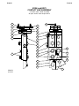
P-101-F (NA3, NA4 and NA5)
P-101-F (NA3, NA4 and NA5)
Part Numbers
K223 SOLENOID ASSEMBLY
(NA3, NA4 and NA5)
Part Numbers
1
2
6
INLET
SOLENOID
TO NOZZLE
ASSEMBLY
9
7
Part Numbers
M12665
7-22-83T
# Indicates a Change This Printing
Part Numbers
ITEM
1
2
6
7
9
DESCRIPTION
Solenoid Assembly, Includes:
Solenoid Mounting Bracket
Solenoid and Valve Assembly
Strain Relief Grommet
Cable Assembly
Name Plate
PART NO.
K223
L5276
M11675-A
T9274-3
M12664
S13246
QTY.
1 2 3 4 5 6 7 8 9
1
1
1
1
1
1
#
3-13-2000
P-101-G
P-101-G
Part Numbers
K129 SUBMERGED ARC TINY TWINARC®
NOTES:
Nozzles with spring loaded contact shoes (illustrated below, right) should be converted to the
newer design by discarding items named below and using the appropriate contact tip holder
and tips or correct one piece contact tip, depending on wire size.
Intermediate design (one piece) contact tips for 1⁄16 and 5⁄64 wire should be converted to
the new (lower replacement cost) contact tip holder and contact tips design by ordering the
appropriate contact tips and tip holder from the parts list below.
Part Numbers
1
5
D
6
A
2
Spring Mounting Bracket
Roll Pin
Pressure Spring Asbly.
3
3
Wing Screw
7
4
C
Part Numbers
4
B
Contact Pressure Shoe
Part Numbers
M11609
4-16-76J
Sub Assembly Illustration
Sub Assembly Illustration
P-101-G.1
P-101-G.1
• Specify Wire Size
# Indicates a Change This Printing
ITEM
1
2
2
3
4
4
4
4
4
5
6
7
7
DESCRIPTION
Twinarc - Complete - Includes All Below
Nozzle Assembly - Stripped - Includes Items 1, 3, 5 & 6
.045 Wire Kit - Includes Items 2, 4, A & B
1/16 Wire Kit - Includes Items 2, 4, 7, A & B
5/64 Wire Kit - Includes Items 2, 4, 7, A & B
3/32 Wire Kit - Includes Items 2, 4, 7, A & B
Nozzle Body Assembly
Guide Tube - .045 & .052 Wire
Guide Tube - 1/16, 5/64 & 3/32 Wire
Nozzle Collar
Contact Tip - .045 Wire
Contact Tip - .052 Wire
Contact Tip - 1/16 Wire
Contact Tip - 5/64 Wire (See Note AA)
Contact Tip - 3/32 Wire
1/2-13 HN
1/2-13 x 1.50 HHCS
Tip Holder - 1/16, 5/64 & 3/32 Wire (Std.), Includes
Nozzle Insert
Tip Holder - (Special Side-by-Side Wire)
PART NO.
QTY.
K129*
M11609
KP1901-1
KP1901-2
KP1901-4
KP1901-3
S13164
KP2092-1
KP2092-2
S13157
KP1979-1
KP1979-2
KP2100-2
KP2100-4
KP2100-3
CF000027
CF000052
KP1988-1
KP2094-4
KP2171-1
1
1
1
1
1
1
1
2
2
1
1
1
2
2
1
1
1
1
2
As Reqʼd
KP1888-1
KP1888-2
1
1
KP1889-1
S14905
T12146-1
M8776-6
KP1970-1
KP1970-2
KP1970-3
S13165
S18583
KP2122-1
See P-100-G
2
1
1
1
2
2
2
1
1
1
1
1 2 3 4 5 6 7 8 9
Sub Assembly Illustration
Note AA When Tip Life is limited by tip being fused over,
the use of T14726-5/64 Tips may result in a lower
overall cost.
A
A
A
B
B
B
C
Sub Assembly Illustration
D
Drive Roll - .045 & .052 Wire
Drive Roll - 1/16 & 5/64 Wire
Drive Roll Assembly - 3/32 Wire, Includes:
Outer Drive Rolls
Center Drive Rolls
Drive Roll Spacer
Drive Roll Key
Wire Guides - .045 & .052 Wire
Wire Guides - 1/16 Wire
Wire Guides - 5/64 & 3/32 Wire
Idle Roll Assembly, Includes:
Idle Roll
Incoming Wire Guide Assembly
Second Wire Reel & Mountings
08-28-2007
P-101-G.2.a
P-101-G.2.a
Part Numbers
K281 WIRE STRAIGHTENER FOR TINY TWINARC®
5A
5
Part Numbers
4
3
4B
4C
2
7
6
10
4A
8
Part Numbers
3C
3B
12
3A
3B
Part Numbers
1
3C
14
9
9
13
05-10-2005
Sub Assembly Illustration
Sub Assembly Illustration
Sub Assembly Illustration
Sub Assembly Illustration
P-101-G.2.b
P-101-G.2.b
USE COLUMN ONE FOR TINY TWINARC
USE COLUMN TWO FOR TWIN MIG TORCH
• Specify Wire Size
# Indicates a Change This Printing
ITEM
1
2
3
3
3A
3B
3C
4
4A
4B
4C
5
5A
5B
6
7
8
9
10
12
13
14
DESCRIPTION
Base
Tension Arm
Roller Assembly, Includes:
Roller Shaft
(2 1/4” Shaft)
Retaining Ring
Roller Assembly, Includes:
Roller Shaft
(2 1/2” Shaft)
Bushing
Retaining Ring
Roller Assembly Includes:
Roller
Bearing Shaft
Retaining Ring
Bearing
Hex Head Cap Screw
Lock Washer
Hex Nut
Incoming Guide Assembly, Includes:
Thumb Screw
Nozzle Insert (Not Shown)
Roll Pin
Adjusting Screw Assembly
Large Pivot
Retaining Ring
Small Pivot Shaft
Roll Pin
Wire Guide Assembly
Set Screw
}
}
PART NO.
QTY.
S15943
S15946
S15953-1
T14099
S9776-1
S15953-3
S18729
S18728
S9776-4
S15953-2
S15950
S18727-1
S11964-7
M9300-83
5/16-18 x 2.00
E106-A3
5/16-18
T14090
T14088
T12576-3
T9967-38
T14092
T14086
S9776-12
T14087
T9967-8
T14093
S11604-21
1
1
1
1
2
1
1
2
2
1
1
1
2
2
1
1
1
1
1
4
2
1
1
2
1
1
1
1
# #
1 2 3 4 5 6 7 8 9
X
X
X
X
X
X
X
X
X
X
X
X
X
X
X
X
X
X
X
X
X
X
X
X
X
X
X
X
X
X
•
•
•
X
X
X
X
X
X
X
X
X
X
X
X
X
X
X
X
X
X
X
X
X
•
X
05-02-2001
P-101-H
P-101-H
Part Numbers
FLUX HOPPER
241
237
SECTION AA
228
Part Numbers
236
250
7
252
6
5
4
3
A
2
229
227
225
235
1
251
226
Part Numbers
Part Numbers
234
L3552
8-21-81P
T12590
1-16-76H
Sub Assembly Illustration
P-101-H.1
# Indicates a Change This Printing
ITEM
225
226
227
228
229
234
235
236
237
241
241
250
250
250
251
252
256
257
Sub Assembly Illustration
Sub Assembly Illustration
Sub Assembly Illustration
P-101-H.1
1
1
2
3
4
5
6
7
ø
For the NA2, use the parts marked “X” in Column 1.
For the NA3, NA4 and NA5, use the parts marked “X” in Column 2.
For the NA454, use the parts marked “X” in Column 3.
DESCRIPTION
Flux Hopper Assembly, Includes:
Flux Hopper Assembly, Includes: (Standard)
Flux Hopper Assembly, Includes:
Flux Hopper Base
Flux Gate Spring
Flux Gate Wear Plate
Flux Gate Spring
Flux Gate Assembly, Includes:
Flux Gate: Sub Assembly
Solenoid Plunger
Spring Retaining Washer
Retaining Ring
Washer
Flux Tube Assembly
Sems Screw
Solenoid
Switch
Cable
Cable
Flux Hopper Assembly
Flux Hopper Assembly (Standard)
Flux Hopper Assembly
Sems Screw
Gasket
Flux Tube (Not Shown)
Flux Tube (Not Shown)
Pointer and Mounting Bracket Assembly, Includes:
Pointer and Mounting Bracket Assembly, Includes:
Pointer
Pointer
Insulating Washer
Washer
Wing Nut
Hex Head Bolt
Insulating Bushing
Pointer Bracket
Door Hinge Assembly
Hex Head Bolt, Hopper Mounting
This part is obsolete and no longer available
PART NO.
L3552-E
L3552-F
L3552-G
L3100
T10573
T10600
T10603
S10131-3
S10131-2
T10598-2
T10599
S9776-4
S9262-98
S10130
T10082-4
S11085
T10616
S13252
M12555
M10818 ø
M10818-1
M13563
T10082-4
T10545
T10642-11
S7748-35
T12590
T12590-1
S10103
S10103-2
S10773-9
S9262-1
T9968-3
T8775-2
T8776
M8226
S16233
1/4-20 x 6
QTY.
1
1
1
1
2
2
1
1
1
1
1
1
1
1
4
1
1
1
1
1
1
1
1
1
1
1
1
1
1
1
2
2
1
1
1
1
2
2
1 2 3 4 5 6 7 8 9
X
•
•
X
X
X
X
X
X
X
X
X
X
X
X
X
X
X
•
•
•
•
X
X
X
X
X
•
X
•
X
X
X
X
X
X
•
•
•
X
•
X
X
X
X
X
X
X
X
X
X
X
X
X
X
•
X
•
X
•
X
X
•
•
•
X
•
X
X
X
X
X
X
X
X
X
•
•
X
X
X
X
X
X
X
X
X
X
X
X
X
X
X
X
X
X
•
X
X
X
•
•
•
•
•
•
•
•
•
•
•
•
•
•
#
04-12-2004
P-101-K
P-101-K
Part Numbers
K148 CONTACT NOZZLE ASSEMBLY
K149 LINC-FILL EXTENSION ASSEMBLY
5
7
14
13
14
Part Numbers
6
8
17
23
105
104
18
15
108A
107
102
25
103
16
108A
106
108
24
Part Numbers
109
4
116
12
111
115
19
1
113
110
9
112
10
114
3
Part Numbers
2
20
22
11
21
11-4-98
Sub Assembly Illustration
Sub Assembly Illustration
Sub Assembly Illustration
Sub Assembly Illustration
P-101-K.1
# Indicates a Change This Printing
ITEM
1
2
3
4
5
6
6
6
7
8
9
10
11
12
13
14
15
16
17
18
19
20
21
22
22
23
24
25
102
103
104
105
106
107
108
108A
109
110
111
112
113
114
114
114
114
114
115
116
P-101-K.1
Use Columns 1, 2 & 3 for Standard K148 Nozzles. Use Columns 4 & 5 for Modified
Series Arc Equipment Nozzles. Use appropriate column for K149 Extensions based
on wire size for standard extensions or Part No. for Modified Series Arc Equipment.
DESCRIPTION
Nozzle Asbly (Wire Size 3/32 - .120-1/8), Includes:
Nozzle Asbly (Wire Size 5/32 - 3/16), Includes:
Nozzle Asbly (Wire Size .068 - 5/64), Includes:
Nozzle Asbly (Wire Size 5/32 - 3/16), Includes:
Nozzle Asbly (Wire Size 3/32 - .120-1/8), Includes:
1/2-13 x 1.5 HHCS
1/2-23 HN
Cable Connector
Roll Pin
Pivot Body
Guide Tube Asbly, 3/32, .120, 1/8 Wire
Guide Tube Asbly, 5/32, 3/16 Wire
Guide Tube Asbly, .068, 5/64 Wire
Set Screw
Insulating Spacer
Flat Washer
Lock Washer
1/4-20 x 1.00 HHCS
Nozzle Body
Insulating Tube
Insulation
Snap Ring
Pivot Pin
Spring
Nozzle Holder
Window Cover
Thread Protecting Collar
Nozzle Collar
Nozzle Tip
Nozzle Tip
Inner Guide
Extension Support Arm Mounting Bracket
Set Screw
Water Cooling Tube Assembly (Not Illustrated)
K149 Linc-Fill Extension Asbly, Includes:
K149 Linc-Fill Extension Asbly, Includes:
K149 Linc-Fill Extension Asbly, Includes:
K149 Linc-Fill Extension Asbly, Includes:
K149 Linc-Fill Extension Asbly, Includes:
Linc-Fill Extension Asbly & L4621-6 Nozzle, Includes:
Extension Arm Asbly
Mounting Block
Set Screw
1/4-20 x 1 3/8 HHCS
Insulation
Insulating Tube
Lock Washer
Plain Washer
1/4-20 HN
Flux Hose Clamp
5/8-11 HJN
Extension Tube - 2” Long
Extension Tube - 1” Long
Extension Tube End (2 3/4 Electrical Stickout)
Extension Tube End (2 1/4 Electrical Stickout)
Extension Tube End
Extension Tube End
Extension Tube End
Flux Hose
Flux Hose
Nozzle Assembly (L4261-6)
PART NO.
K148A
K148B
K148C
L4621-4 & -6
L4621-5
CF000052
CF000027
S12576
T9967-35
M10340-1
KP1974-1
KP1974-2
KP1974-3
S11604-19
T12157
S9262-23
E106A-2
CF000015
M11327
T7028-51
S12579
S9776-25
T12158
T10247-8
S13762
S7748-64
S13805
S13804
KP1973-1
KP1991-1
KP1980-1
S13758
S11604-19
T12928
K149-3/32 Wire
K149-.120 Wire
K149-1/8 Wire
K149-5/32 Wire
K149-3/16 Wire
M13868
S13757
S13758
S11604-19
CF000118
T8477-16
T11851-3
E106A-2
S9262-23
CF000017
T12929
CF000140
KP1975-2
KP1975-1
KP1976-3
KP1990-1
KP1976-1
KP1976-4
KP1976-2
T10642-34
S7748-35
See Above List
QTY.
1
1
1
1
1
1
1
1
1
1
1
1
1
1
1
2
2
2
1
1
2
2
1
1
1
1
1
1
1
1
1
1
1
1
1
1
1
1
1
1
1
1
1
2
2
2
2
2
2
1
1
1
1
1
1
1
1
1
1
1
1
1
X
•
•
•
•
X
X
X
X
X
X
•
•
X
X
X
X
X
X
X
X
X
X
X
X
X
X
X
X
•
•
•
•
X
X
•
•
•
•
•
X
X
X
X
X
X
X
X
X
X
X
•
•
X
X
•
•
•
X
X
•
2
•
X
•
•
•
X
X
X
X
X
•
X
•
X
X
X
X
X
X
X
X
X
X
X
X
X
X
X
X
•
•
•
•
X
•
X
•
•
•
•
X
X
X
X
X
X
X
X
X
X
X
•
X
•
•
X
•
•
X
X
•
3
•
•
X
•
•
X
X
X
X
X
•
•
X
X
X
X
X
X
X
X
X
X
X
X
X
X
X
X
•
X
X
•
•
X
•
•
X
•
•
•
X
X
X
X
X
X
X
X
X
X
X
X
•
•
•
X
•
•
X
X
•
4
•
•
•
X
•
X
X
X
X
X
•
X
•
X
X
X
X
X
X
X
X
X
X
X
X
•
X
X
X
•
•
X
X
•
•
•
•
X
•
•
X
X
X
X
X
X
X
X
X
X
X
X
•
•
•
•
X
•
X
X
•
5
•
•
•
•
X
X
X
X
X
X
X
•
•
X
X
X
X
X
X
X
X
X
X
X
X
•
X
X
X
•
•
X
X
•
•
•
•
•
X
•
X
X
X
X
X
X
X
X
X
X
X
X
•
•
•
•
•
X
X
X
•
6 7 8 9
#
•
•
•
•
•
X
X
•
•
X
X
X
X
X
X
•
X
•
X
•
•
•
•
X
•
•
X
08-28-2007
P-101-L
P-101-L
Part Numbers
K225 SUBMERGED ARC TWINARC KIT
129
103
101
104
102
105
108
107
119
106
125
120
Part Numbers
110
124
118
123
122
126
117
127
111
109
116
115
121
113
114
Part Numbers
Part Numbers
128
L5314
6-12-81J
112
Sub Assembly Illustration
Sub Assembly Illustration
Sub Assembly Illustration
Sub Assembly Illustration
P-101-L.1
P-101-L.1
# Indicates a Change This Printing
ITEM
101
102
103
104
105
106
107
108
109
110
111
112
112
112
113
114
115
116
117
118
119
120
121
122
123
124
125
126
127
128
129
DESCRIPTION
Twinarc - Complete - Includes All Below
Nozzle Assembly - Includes Items 101 through 129
Adapter Plate
Adapter Insulation
Socket Head Screw
Washer
Insulating Washer
Insulating Bushing
Electrode Guide Tube
Socket Plate
Nozzle Body
Current Bar
1/4-20 x 1.00 HHCS
Center Contact Block (.375 Electrode Spacing)
Center Contact Block (.500 Electrode Spacing)
Center Contact Block (.625 Electrode Spacing)
Line Up Plate
Socket Head Screw
Spring
Spring Insulation
Insulating Bushing
Washer
Lock Washer
1/4-20 x 1.00 HHCS
Contact Jaw
1/2-13 x 1.50 HHS
1/2-13 HN
Socket Head Screw
Washer
Nameplate
Drive Screw
Flux Tube Support Assembly
5/16-18 x 3/4 HHCS
Outer Drive Rolls
Center Drive Roll
Drive Roll Spacer
Idle Roll Assembly
Drive Roll Key
Wire Guide Tubes - Upper & Lower
Wire Straightener
Second Wire Reel & Reel Mounting
PART NO.
QTY.
K225
L5314-1
M12478-1
T8391
T9447-10
S9262-23
S10773-12
T8390
KP2084-1
S9842
M7913
S9544
CF000015
T10252-1
T10252-2
T10252-3
T10245
T9447-11
S7664
T8724
T8725
S9262-23
E106A-2
CF000015
T10266
CF000052
CF000027
T9447-10
T10248
S9556
S8025-8
T10684
CF000049
KP1889-1
S14905
T12146-1
S13165
M8776-6
KP1982-1
See P-100-M
See P-100-G
1
1
4
4
8
4
2
1
1
1
4
1
1
1
1
2
2
4
4
4
4
4
2
1
1
2
2
1
2
1
2
2
1
1
1
1
2
1
1
1 2 3 4 5 6 7 8 9
08-28-2007
P-101-L.2
P-101-L.2
Part Numbers
K239 INNERSHIELD TWINARC KIT
3
2
1
4
20
5
19
26
7
Part Numbers
27
6
9
8
10
12
11
18
25
17
13
21
14
N.B.
15
22
Part Numbers
Part Numbers
23
24
L5421
3-22-85M
16
Water cooled Socket HD. screw
jacket asbly.
Part of item 14
Wire guide
block asbly.
Sub Assembly Illustration
Sub Assembly Illustration
Sub Assembly Illustration
Sub Assembly Illustration
P-101-L.3
P-101-L.3
# Indicates a Change This Printing
ITEM
1
2
3
3
3
3
4
5
6
7
8
8
9
10
11
12
13
14
15
15
15
15
16
17
18
19
19
20
21
22
23
24
25
26
27
ø
DESCRIPTION
Twinarc - Complete - Includes All Below
Nozzle Assembly
Adapter Plate & Roll Pin Assembly
Hex Head Screw
Socket Head Screw
Flat Washer
Insulating Washer
Insulating Bushing
Adapter Insulation
Socket Plate
Socket Head Screw
Electrode Guide Tube
Nameplate
Drive Screw
Round Head Screw
Lock Washer
Clamp
Contact Block
Socket Head Screw
Jacket & Guide Block Assembly
Hex Head Screw
Flat Washer
Lock Washer
Hex Nut
Contact Tip
Current Bar
Hex Head Screw
Hex Head Screw
Hex Nut
Nozzle Body
Conductor Bar Insulation
Insulating Sleeve
Tip Insulation
Insulating Sleeve
Water Jacket Insulation
Flat Washer
Flat Washer
Outer Drive Rolls
Center Drive Roll
Drive Roll Spacer
Idle Roll Assembly
Drive Roll Key
Wire Guide Tubes - Upper & Lower
Wire Straightener
Second Wire Reel & Reel Mounting
This part is obsolete and no longer available.
PART NO.
K239
L5421-1 ø
M12478-1
5/16-18 x .75
T9447-10
S9262-23
S10773-12
T8390
T8391
S9842
T9447-10
T10251-1
S9556
S8025-8
1/4-20 x .50
E106A-2
T8970-14
S15482-1
T9447-7
S15487-1
3/8-16 x 2.25
S9262-120
E106A-16
3/8-16
T14050-3/32
S15483
1/4-20 x 1.00
1/2-13 x 1.50
1/2-13
M7913
T13831-2
T13829
T13831-1
T13830-1
T13832
S9262-23
S9262-103
S14904
S14905
T12146-1
S13165
M8776-6
S14901
See P-100-N
See P-100-G
QTY.
1 2 3 4 5 6 7 8 9
#
1
2
4
4
8
4
1
1
2
2
1
2
2
2
2
1
2
1
2
4
2
2
2
1
4
1
1
1
1
2
1
2
1
2
2
2
1
1
1
1
2
1
1
02-04-2002
P-101-M
P-101-M
Part Numbers
K231 (and K31*)
CONTACT NOZZLE ASSEMBLY
* For K31, order K231 assembly.
All parts are interchangeable.
113B
113A
125
Part Numbers
113C
117
118
121
111A
116
Part Numbers
110
114
115
111
124
122
Part Numbers
123
10-18-2006
Sub Assembly Illustration
Sub Assembly Illustration
Sub Assembly Illustration
P-101-M.1
# Indicates a Change This Printing
ITEM
110
111
111A
113A
113B
113C
114
115
116
117
118
119
119
120
120
121
122
123
123
123
123
123
123
123
123
123
124
124
125
125
Sub Assembly Illustration
P-101-M.1
*
Use only the parts marked “X” in the column under the
heading number called for in the model index page.
DESCRIPTION
Nozzle Assembly, Includes Items 110 thru 125 as
appropriate for wire size specified
Nozzle Assembly, for LT34 ONLY, Includes Items
110, 111, 118, 121 and 122; Order Items 119,
120, 123, 124 and 125 separately for the
desired wire size
Nozzle Insulator
Nozzle Body
Roll Pin
Cone Body Assembly, Includes:
Flux Cone Plug
Roll Pin
Retaining Nut
Flux Cone
Locking Ferrule
Thumb Screw
Special Socket Head Screw
Rubber Flux Tube (Not Shown)
Rubber Flux Tube, LT34 Only (Not Shown)
Steel Flux Tube (Not Shown)
Steel Flux Tube, LT34 Only (Not Shown)
1/2-13 x 1.50 HHCS - Lead to Nozzle
1/2-13 HN - Lead to Nozzle
Contact Tip - 7/32 Wire Size
Contact Tip - 3/16 Wire size
Contact Tip - 5/32 Wire Size
Contact Tip - 1/8 Wire Size
Contact Tip - 3/32 Wire Size
Contact Tip - 3/32 Wire Size; (3/8-24 Thread) Old Style
Contact Tip - 3/32 Wire Size; (5/16-18 Thread)
Contact Tip - 5/64 Wire Size; (3/8-24 Thread) Old Style
Contact Tip - 5/64 Wire Size; (5/16-18 Thread)
See Note 1
Adapter for 3/32 and 5/64 S8087 Tips
(With 3/8-24 Female Thread)
Adapter for 3/32 and 5/64 T14050 Tips
(With 5/16-18 Female Thread)
Nozzle Insert for 3/32 and 5/64 Wire (For NA)
Nozzle Insert for 5/64 Wire (For LAF & LT)
Mounting Clip (For Mounting Nozzle on LAF2)
Nozzle Extension (5.38” long) (For 3/32 & Larger Wire)
PART NO.
QTY.
1 2 3 4 5 6 7 8 9
K231*
1
X •
M8241-1
S10493-1
S10157
T9967-10
M8249
S10138
T9967-30
S10147
KP2085-1
T10574
T9078-1
T10570
T10642-1
T10642-11
T6996-9
S10487
CF000052
CF000027
KP1962-5
KP1962-2
KP1962-4
KP1962-1
KP1962-3
KP2082-1
KP2100-3
KP2082-2
2
1
1
1
1
1
1
1
1
1
1
1
1
1
1
1
1
1
1
1
1
1
1
1
1
1
•
X
X
X
X
X
X
X
X
X
X
X
X
•
X
•
X
X
X
X
X
X
X
X
X
X
T14050-5/64
1
X X
See Note 2
1
X X
KP1992-1
S15106-3/32
KP2121-2
T10714 ø
S12003
1
1
1
2
As Reqʼd
X
X
X
X
X
X
X
X
X
•
•
•
•
•
•
•
•
•
X
•
X
X
X
X
X
X
X
X
X
X
X
#
X
•
X
•
•
Specify Wire Size
Note 1 When tip life is limited by tip being fused over, the
use of T14726-5/64 Tips may result in a lower
overall cost.
Note 2 This adapter is no longer available, order Adapter
S16844 and the appropriate T14050 Tips or
T14726-5/64 Tip.
10-18-2006
P-101-N
P-101-N
Part Numbers
K226 (and K32*)
CONTACT JAW ASSEMBLY
* For K32, order a K226 assembly.
All parts are the same except Item 8.
1
2
3
28
8
9
10
4
Part Numbers
11
5
12
6
13
14
15
16
23
17
7
18
20
19
27
Part Numbers
Part Numbers
26
20
24
21
22
25
M13879
6-12-81J
Sub Assembly Illustration
Sub Assembly Illustration
Sub Assembly Illustration
P-101-N.1
# Indicates a Change This Printing
ITEM
DESCRIPTION
Contact Jaw Assembly - One Rectangular and One
Tapered Jaw - For 1/8 thru 7/32 Wire, Includes:
Contact Jaw Assembly - Two Tapered Jaws - For
3/32 and 1/8 Wire, Includes:
1
Socket Head Screw
2
Washer
3
Insulating Washer
4
Insulating Bushing
5
Cover Plate
6
Lead Block
7
Hex Jam Nut
8
Adapter Plate, Rectangular*
9
Insulation Plate
10
Bottom Wire Guide
11
Spring Insulation
12
Hex Head Cap Screw
13
Insulating Bushing
14
Hex Head Cap Screw
15
Hex Head Cap Screw
15N
Hex Jam Nut
16
Lock Washer
17
Plain Washer
18
Spring
19
Hex Head Cap Screw
20
Plain Washer
21
Contact Block - Rectangular
21
Contact Block - Tapered
22
Hex Head Cap Screw (K226-R Only)
23
Hex Head Cap Screw (K226-R)
23
Hex Head Cap Screw (K226-T)
24
Braided Lead (K226-R Only)
25
Contact Jaw
26
Flux Tube Clip
27
Hex Head Cap Screw
28
Hex Head Screw
29
Flux Hose
30
Flux Hose Tip
*
Sub Assembly Illustration
P-101-N.1
PART NO.
K226-R
K226-T
T9447-10
S9262-23
S10773-12
T8390
T8404
S7273
3/8-16
M12478*
T8391
M6656
T8724
1/4-20 x 1.00
T8725
3/8-16 x 1.00
1/2-13 x 1.75
1/2-13
E106A-2
S9262-23
S7664
3/8-16 x 1.25
S9262-4
S16640-1
S16640-2
3/8-16 x .75
3/8-16 x 1.50
3/8-16 x 1.25
S7266
S16640-2
T10683
3/8-16 x 1.50
5/16-18 x .75
T10642-2
S7748-35
QTY.
1 2 3 4 5 6 7 8 9
1
1
4
4
8
4
1
1
4
1
1
1
2
2
2
2
2
2
2
2
1
2
2 or 3
1
1
1
1
1
1
1
1
1
2
1
1
Item 8 for K32 Jaws Sold with LAF and LT3
Tractors was round – Part S7258.
02-04-2002
G1326
5-15-81B
76
73
Part Numbers
37
B
20
21
C
.50
5.00
1
19
TAPE ITEM 22 TO
HANDLE WITH 75
WIDE TAPE PER E651
FOR SHIPMENT
2
3
93
92
94
91
94
93
9
88
89
CONTROL BOX
7
6
34
24
5
32
33
26
31
25
A
23
FULL SCALE CUT-AWAY VIEW SHOWING
NA3 & NA4 CONTROL BOX MOUNTING
CONTROL BOX
FULL SCALE CUT-AWAY VIEW SHOWING
LAF3,4, & 5 CONTROL BOX MOUNTING
901 91
Part Numbers
FULL SCALE VIEW SHOWING UPPER
GUIDE WHEELS & MOUNTING
STENCIL CODE NUMBER
.19 HIGH NUMBERS
Part Numbers
27
28
29
35
30
Part Numbers
P-101-P
(Supersedes P-52-C)
P-101-P
(Supersedes P-52-C)
TRAVEL CARRIAGE GENERAL ASSEMBLY
3-8-82
ITEM
A
B
1
2
2
2
3
5
5
5
6
6
7
7
Sub Assembly Illustration
9
9
C
C
Sub Assembly Illustration
P-101-P.1.a
(Supersedes P-52-C.1)
# Indicates a Change This Printing
Sub Assembly Illustration
Sub Assembly Illustration
P-101-P.1.a
(Supersedes P-52-C.1)
19
19
20
20
21
21
22
23
24
25
26
27
27
28
29
29
30
31
32
ø
For K23 & K236 Models (below code 7500), use the parts marked “X” in Column 1.
For K247 Models (above code 7500), use the parts marked “X” in Column 2.
For K247-HC Models (above code 7500), use the parts marked “X” in Column 3.
DESCRIPTION
Motor and Gear Box Assembly
Control Panel Assembly
Carriage Frame
Upper Guide Wheel Assembly, Includes:
Upper Guide Wheel Assembly, Includes:
Upper Guide Wheel Assembly, Includes:
Shaft
Shaft
Bearing
Bearing
Retaining Ring
Roll Pin
Lockwasher - Guide Wheel Mounting
Washer - Guide Wheel Mounting
Lower Bearing Bar Assembly
Lower Bearing Bar Assembly
Lower Bearing Bar Assembly
Spacer - Thin
Spacer - Thin
Spacer - Thick
Spacer - Thick
Lockwasher, Lower Bearing Bar Mounting
Socket Head Screw
Socket Head Screw
Head Mounting and Lift
Head Mounting and Lift
Head Mounting Parts
Lift Handle
Lift Handle
Lift Handle Stud
Lift Handle Stud
Set Screw, Lift Handle and Stud Mounting
Hex Jam Nut, Locking Set Screw
Roll Pin, Lift Handle Mounting
Roller, Mounts Item C thru Crank Bracket
Gear Box Mounting Plate
Flat Head Screw
Drive Wheel
Key, Drive Wheel to Motor
Spacer
Lockwasher
Nut, Drive Wheel to Motor
Swivel Motor Mount
Swivel Motor Mount
Oil Cup
Hex Head Bolt
Hex Head Bolt
Lockwasher
Upper Spring Bracket
Hex Head Bolt
This part is obsolete and no longer available.
PART NO.
QTY.
See P-101-R
See P-101-O
G1384
T5335-1
T13876
T13875
T10647
S15558
M9300-6
M9300-67
S9776-50
T9967-43
E106A-5
S9262-1
S10299
M12980-2
M12980-1
S10262-1 ø
S10262-5
S10262-2 ø
S10262-4
E106A-4
T9447-14 ø
T9447-49
L3116
L5460
See P-101-Q
M8385
M12968
T10652
T13872
S11604-11
3/8-16
T9967-30
T8128
M8485 ø
5/16-18 x .625
T13586
M8776-6
S9262-44
T9860-2
T10552
S10288
S15772
T8679
1/2-13 x 1.00
1/2-13 x 1.25
E106A-5
S10379
3/8-16 x .75
1
4
4
4
1
1
1
1
2
4
6
8
2
2
2
4
4
8
2
4
4
2
1
1
1
1
1
1
1
2
1
1
1
1
4
1
1
1
1
1
2
2
2
2
2
2
1
2
1 2 3 4 5 6 7 8 9
X
X
•
•
X
•
X
•
•
•
X
X
X
•
•
X
•
X
•
X
X
•
X
•
X
X
•
X
•
X
X
•
X
X
X
X
X
X
X
X
X
•
X
X
•
X
X
X
X
•
X
•
•
X
X
•
X
X
•
•
•
X
•
•
X
•
X
•
•
X
•
X
X
•
X
•
X
•
•
X
X
X
X
X
X
X
X
X
X
•
X
•
X
X
X
X
X
•
•
X
•
X
•
X
X
X
•
•
•
•
X
•
X
•
•
•
•
X
•
X
X
•
X
•
X
•
•
X
X
X
X
X
X
X
X
X
•
X
X
•
X
X
X
X
#
06-06-2001
P-101-P-1.b
(Supersedes P-52-C.1)
For K23 & K236 Models (below code 7500), use the parts marked “X” in Column 1.
For K247 Models (above code 7500), use the parts marked “X” in Column 2.
For K247-HC Models (above code 7500), use the parts marked “X” in Column 3.
# Indicates a Change This Printing
ITEM
33
34
35
35
37
73
DESCRIPTION
76
PART NO.
Lockwasher
E106A-4
Spring
T5338
Shim - Swivel Motor Mount
T10778-1
Shim - Swivel Motor Mount
T10778-2
Cable Clamp
M8501
Choke Coil
M8424
Cable - To Travel Receptacle in Control Box, Includes: M8377
Plug
S10272
Wire Reel Support
L3154
88
89
90I
90A
91
92
93
94
Control Box Mounting Parts
Insulation Tube
Insulation Washer
Insulation Spacer
Adapter Plate
Hex Head Screw
Plain Washer
Lockwasher
Hex Nut
T7305-19
S10773-12
S10300
S15082
1/4-20 x .75
S9262-98
E106A-2
1/4-20
QTY.
2
1
As Reqʼd
4
1
1
1
1
1
1
X
X
X
X
X
X
X
X
X
2
X
X
X
X
X
X
X
X
X
3 4 5 6 7 8 9
X
X
X
X
X
X
X
X
X
4
4
1
1
6
6
6
6
X
X
X
X
X
X
X
X
X
X
X
X
X
X
X
X
X
X
X
X
X
X
X
X
Sub Assembly Illustration
Sub Assembly Illustration
Sub Assembly Illustration
P-101-P.1.b
(Supersedes P-52-C.1)
Sub Assembly Illustration
Carriage Type Number
For LAF & NA2
For NA3 & NA4
For NA3 & NA4
K23-F
K23-M
K23-S
K236-F
K236-M
K236-S
K247 & -HC -F
K247 & -HC -M
K247 & -HC -S
Gear Ratio
Fast
144 : 1
Medium 324 : 1
Slow
648 : 1
3-8-82
P-101-Q
(Supersedes P-52-D)
P-101-Q
(Supersedes P-52-D)
Part Numbers
HEAD MOUNTING AND LIFT MECHANISM
18
15
11
Part Numbers
17
13
12
10
Part Numbers
Part Numbers
14
# Indicates a Change This Printing
For K23 and K236 Models (Below Code 7500) use the parts marked “X” in column 1.
For K247 and K247-HC Models, (Above Code 7500) and K325 and K325-HC Models, use
the parts marked “X” in column 2.
ITEM
DESCRIPTION
C Head Mounting and Lift Mechanism (Includes all Below)
C Head Mounting and Lift Mechanism (Includes all Below)
10
Head Lift Mounting Plate
10
Head Lift Mounting Plate
11
Lift Link
11
Lift Link
12
Roller Shaft
13
Roller
14
Roll Pin - Roller to Roller Shaft
15
Crank Link Shaft
15
Crank Link Shaft
16
Roll Pin - Locates Lift Link on Crank Link Shaft
17
Link Shaft
17
Link Shaft
18
Crank Bracket
18
Crank Bracket
ø
This part is obsolete and no longer available.
PART NO.
L3116
L5460
S10292
S15553
S10296
S15552
S10266-1
T10654
T9967-6
S10266-3 ø
S10266-4
T9967-1
S10266-2 ø
S10266-4
S10285 ø
T13874
QTY.
1
1
1
1
2
2
2
4
4
1
1
4
1
1
1
1
1
X
•
X
•
X
•
X
X
X
X
•
X
X
•
X
•
2 3 4 5 6 7 8 9
•
X
•
X
•
X
X
X
X
•
X
X
•
X
•
X
6-16-2000
#
#
#
P-101-R
(Supersedes P-52-F)
P-101-R
(Supersedes P-52-F)
Part Numbers
CARRIAGE DRIVE MOTOR AND GEAR CASE
211
210
209
199
191
194
185
186
182
184
177 178
Part Numbers
201
201
175
181
195
202
179
183
205
180
176
200
178 177
213
A-356
207 208 204 203 206 189 188
# Indicates a Change This Printing
Part Numbers
ITEM
A
A
A
PART NO.
Drive Motor and Gear Case Assembly, 144-1 Ratio,
Includes All items in Column 1 Marked “X”.
L3094-1* ø
Drive Motor and Gear Case Assembly, 324-1 Ratio,
Includes All items in Column 2 Marked “X”.
L3094-2*
Drive Motor and Gear Case Assembly, 648-1 Ratio,
Includes All items in Column 3 Marked “X”.
L3094-4* ø
Gear Case
G1027 ø
Dust Cap - For Output Shaft
T10559
Dust Cap Gasket
T10649-1
Dust Cap Gasket
T10649-2 ø
Flat Head Screw - Dust Cap to Case
10-24 x 1/2
Dust Cap - For Cross Shaft
T10672 ø
QTY.
1 2 3 4 5 6 7 8 9
1
X •
1
• X •
1
1
1
•
X
X
X
X
X
X
•
X
X
As Reqʼd X
As Reqʼd X
4
X
1
X
•
X
X
X
X
X
X
X
#
#
Part Numbers
175
176
177
178
179
180
DESCRIPTION
Use only the parts marked “X” in the column under the
heading number called for in the model index page.
ø
This part is obsolete and no longer available.
08-13-2001
Sub Assembly Illustration
Sub Assembly Illustration
Sub Assembly Illustration
Sub Assembly Illustration
P-101-R.1
P-101-R.1
# Indicates a Change This Printing
Use only the parts marked “X” in the column under the
heading number called for in the model index page.
ITEM
DESCRIPTION
181
182
183
184
185
186
187
188
189
190
Caution Plate
Round Head Screw - Dust Cap to Gear Case
Lock Washer
Small Bearing Cage
Small Bearing Cage Gasket
Flat Head Screw - Small Cage to Gear Case
Large Bearing Cage
Large Bearing Cage Gasket
Flat Head Screw - Large Cage to Gear Case
Oil Seal - Output Shaft
Motor Assembly - 144-1 Ratio Only, Includes:
Motor Assembly - 324-1 and 648-1 Ratio, Includes:
Motor
Brush and Spring Assembly
Brush Cap
Phillips Flat Head Screw, Motor to Base
Input Worm, 144-1 Ratio Only
Input Worm, 324-1 and 648-1 Ratio
Roll Pin, Input Worm to Motor Shaft
Four Contact Plug
Oil Throw Ring
Cross Shaft Assembly, 144-1 Ratio Only, Includes
Items 199 through 202
Cross Shaft Assembly, 324-1 Ratio Only, Includes
Items 199 through 202
Cross Shaft Assembly, 628-1 Ratio Only, Includes
Items 199 through 202
Cross Shaft, 224-1 Ratio Only
Cross Shaft, 324-1 Ratio Only
Cross Shaft, 648-1 Ratio Only
Input Worm Gear, 144-1 Ratio Only
Input Worm Gear, 224-1 and 648-1 Ratio
Ball Bearing
Woodruff Key
Output Shaft Assembly, 144-1 Ratio Only, Includes
Items 203 through 208
Output Shaft Assembly, 324-1 Ratio Only, Includes
Items 203 through 208
Output Shaft Assembly, 648-1 Ratio Only, Includes
Items 203 through 208
Output Shaft
Output Shaft Worm Gear, 144-1 Ratio Only
Output Shaft Worm Gear, 324-1 Ratio Only
Output Shaft Worm Gear, 648-1 Ratio Only
Ball Bearing
Ball Bearing
Snap Ring
Woodruff Key
Motor Base Gasket
Round Head Screw, Motor Base to Gear Case
Lock Washer, Motor Base to Gear Base
Slotted Pipe Plug
Gear Box Lubricant
191
199
199
199
200
200
201
202
203
204
204
204
205
206
207
208
209
210
211
213
PART NO.
QTY.
1 2 3 4 5 6 7 8 9
S10346
#10-24 x 1/2
E106A-1
S10077
S10084
#10-24 x 1/2
S10079
S10085
#10-24 x 1/2
S7611-5
M10301-2
M10301-1
NSS
L3117-9 ø
L3117-7 ø
8-32 x 1
S10088-3
S10088-1
T9967-3
T10662
S10773-6
1
4
4
1
1
4
1
1
6
1
1
1
1
2
2
4
1
1
1
1
1
X
X
X
X
X
X
X
X
X
X
X
•
X
X
X
X
X
•
X
X
X
X
X
X
X
X
X
X
X
X
X
•
X
X
X
X
X
•
X
X
X
X
X
X
X
X
X
X
X
X
X
X
•
X
X
X
X
X
•
X
X
X
X
S10080-3 ø
1
X •
•
S10080-6
1
• X •
S10080-8
S10075-3 ø
S10075-4
S10075-2
S10087-3
S10087-1
M9300-29
#405
1
1
1
1
1
1
2
1
•
X
•
•
X
•
X
X
•
•
X
•
•
X
X
X
X
•
•
X
•
X
X
X
S10083-3 ø
1
X •
•
S10083-4
1
• X •
S10083-2
S10078
S10076-3 ø
S10076-4
S10076-2
M9300-27
T10776
S9776-5
#606
T8364
#10-24 x 3/4
E106A-1
S10780-5 ø
T8484
1
1
1
1
1
1
1
1
1
1
3
3
1
1
•
X
X
•
•
X
X
X
X
X
X
X
X
X
•
X
•
X
•
X
X
X
X
X
X
X
X
X
#
#
#
X
X
•
•
X
X
X
X
X
X
X
X
X
X
* To order a gear box assembly without a motor,
add “-W” to this assembly number.
ø
This part is obsolete and no longer available.
NSS - Not sold separately.
02-20-2002
P-101-S
P-101-S
Part Numbers
K29 VERTICAL HEAD LIFT ASSEMBLY
NA1, 2, 3, 4 and 5 and LAF3, 4 and 5
18
14
13
20
19
12
17
16
15
2
Part Numbers
1
5
3
22
7
6
8
23
4
11
4
9
24
10
25
3
Part Numbers
Part Numbers
21
L5882
11-13-81P
Sub Assembly Illustration
Sub Assembly Illustration
Sub Assembly Illustration
Sub Assembly Illustration
P-101-S.1
P-101-S.1
# Indicates a Change This Printing
ITEM
1
1
2
2
3
3
4
4
5
6
7
8
9
10
11
12
13
14
15
16
17
18
19
20
21
22
23
24
25
In mid 1978 the K29 was redesigned. Old design assemblies may be identified by three socket head
screws in the head lift lock area. New design assemblies have only one socket head screw. Use
parts marked “X” in Column 1 for old design. Use parts marked “X” in Column 2 for new design.
DESCRIPTION
Head Lift Housing
Head Lift Housing
Head Lift Tube
Head Lift Tube
Head Lift Lock Pin
Locating Key
Socket Head Cap Screw
Socket Head Cap Screw
Spring
Spring Retainer
Snap Ring
Head Lift Screw Assembly, Includes:
Head Lift Screw
Ball Bearing
Snap Ring
Gear
Woodruff Key
Boot
Clamp
Clamp
Adjusting Shaft Assembly, Includes:
Crank Arm Assembly
Snap Ring
Thrust Washer
Drive Pin
Shaft
Bearing Retainer
Needle Bearing
Oil Seal
Round Head Screw
Lock Washer
Oil Cup
Needle Bearing
Thrust Washer
Cover Plate
Lock Washer
Round Head Screw
Expansion Plug
Shim
Locking Plate
Socket Head Cap Screw
Lock Washer
PART NO.
K29
L5881
M8228
M8228-1
S16067
T12121
T9447-34
T9447-32
T10247-11
S11295-5
S9776-14
S10114
S10094
M9300-6
S9776-3
S10096-1
#404
S10442
S10888-11
S10888-8
S10097
T10543
S9776-3
S9262-38
T8433
T10544
S10093
S7844
S7611-13
#10-24 x .50
E106A-1
T10643
S10116-1
S9262-37
T14606
E106A-1
#10-24 x .50
T10542-1
T10601
T12120
T9447-33
E106A-2
QTY.
1
1
1
1
1
1
1
1
1
1
1
1
1
1
1
1
1
1
1
1
1
1
1
1
1
1
1
1
1
2
2
1
1
1
1
2
2
1
As Reqʼd
1
2
2
1 2 3 4 5 6 7 8 9
X
•
X
•
•
X
X
•
•
•
•
X
X
X
X
X
X
X
X
X
X
X
X
X
X
X
X
X
X
X
X
X
X
X
X
X
X
X
X
X
X
X
•
X
•
X
X
•
•
X
X
X
X
X
X
X
X
X
X
X
X
X
X
X
X
X
X
X
X
X
X
X
X
X
X
X
X
X
X
X
•
•
•
•
02-04-2002
P-101-T.a
P-101-T.a
Part Numbers
HIGH FREQUENCY UNIT K238
RESISTOR
TRANSFORMER
T13260-3
HI-FREQ
CAPACITOR
CASE
TERMINAL STRIP
CAPACITOR
Part Numbers
RELAY
Part Numbers
SPARK GAP
ASSBLY
AIR CORE
TRANSFORMER
SPARK GAP
MOUNTING PANEL
AND BRACKET
Part Numbers
L6329
10-21-83
6-15-84
P-101-T.b
# Indicates a Change This Printing
ITEM
DESCRIPTION
High Frequency Unit, Includes:
Capacitor
Transformer
Resistor
Case
Case Cover
Nameplate
Terminal Strip
Number Plate
Relay
Spark Gap Assembly
Electrode
R. F. Choke
Air Core Transformer
PART NO.
K238
S17571
M15359 ø
S10404-53
L3815-1
L3816
M9591
S13323-1
T10726-92
S12807
S16501-3
T11236-1
T12218-1
L4283
QTY.
1 2 3 4 5 6 7 8 9
1
1
#
1
1
1
1
1
1
1
1
4
2
1
#
Sub Assembly Illustration
Sub Assembly Illustration
Sub Assembly Illustration
Sub Assembly Illustration
P-101-T.b
ø
This part is obsolete and no longer available.
07-11-2002
P-101-U.a
P-101-U.a
Part Numbers
K386 NARROW GAP DEEP GROOVE
SUBMERGED ARC NOZZLE
30
1
2
3
4
5
6
26
Part Numbers
29 28 27
N.E.
SECTION THRU NOZZLE TIP
(WITH JACKET REMOVED)
DOUBLE SIZE
8
9
31
10 11 12 13 14 15 16 17
7
25
19
20
21
22 23
24
G1653
5-18-84
Part Numbers
Part Numbers
18
9-11-84
Sub Assembly Illustration
Sub Assembly Illustration
P-101-U.b
# Indicates a Change This Printing
ITEM
1
2
3
4
5
6
7
8
9
10
11
12
13
14
15
16
17
18
19
20
Sub Assembly Illustration
21
Sub Assembly Illustration
P-101-U.b
22
23
24
25
26
27
28
29
30
31
DESCRIPTION
PART NO.
QTY.
Nozzle Tip
Hollow Set Screw
Ceramic Insert
Ceramic Insert
Spring Liner
Nozzle Tube Assembly
Insulation Jacket
Cooling Bar Assembly
Nozzle Pivot Hub Assembly
Set Screw
Key
Rotational Lock Screw Assembly
Snap Ring
Pivot Assembly
Nozzle Insulator Assembly
Socket Head Screw
Nozzle Insert Assembly
Pressure Belt
Pressure Arm Assembly
Socket Head Cap Screw
Flux Tube Clamp
Button Head Socket Screw
Hex Head Screw
Plain Washer
Wing Nut
Flux Tube
Pivot Housing Arm
Lock Washer
Hex Head Screw
Mounting Clamp Assembly
Roll Pin
Plain Washer
Roll Pin
Pivot Handle
Hex Head Screw
Flange Nut
Nozzle Tube Strap
T14879-3/32
T12932-2
T12576-1
T12576-2
T12931-35
S17543
S17545
S17546
T14891
S11604-42
M8776-89
T14885
S9776-46
T14883
S10493
T10570
S15106-1
T14889
T14890
T9447-56
S17542
T11551-6
1/4-20 x 1.25
S9262-23
T9968-1
T14887
M14717
E106-A14
5/16-18 x 1.50
S17550
T9967-43
S9262-104
T9967-29
T14939-1
1/2-13 x 1.25
T3960
T14974
1
1
1
4
1
1
1
1
1
2
1
2
1
1
1
1
1
1
1
1
1
2
1
1
1
1
1
3
3
1
1
2
1
2
1
1
1
Items Not Illustrated:
Flux Hopper Extension Bracket
Flux Hopper Extension Pin
Extension Pin Nut
Flex Tube
S17558
S17559
1/4-20
T10642-106
2
2
2
1
1 2 3 4 5 6 7 8 9
#
9-11-84
P-101-V
P-101-V
Part Numbers
K405 AUTOMATIC INNERSHIELD NOZZLE
9
3
2
7
5
6
4
Part Numbers
8
1
Part Numbers
Part Numbers
L7102
5-17-85
# Indicates a Change This Printing
ITEM
DESCRIPTION
PART NO.
QTY.
1
1
1
1
1
2
2
3
4
5
6
7
8
9
Nozzle Tip - .062 Wire Size
Nozzle Tip - .068 Wire Size
Nozzle Tip - 5/64 Wire Size
Nozzle Tip - 3/32 Wire Size
Nozzle Tip - .120 Wire Size
Straight Nozzle Assembly .062 - 3/32 Wire Size
Straight Nozzle Assembly .122 Wire Size
Collar
Nozzle Body Assembly
Socket Head Screw
Nozzle Insulator Assembly
Nozzle Insert Assembly .062 - 3/32 Wire Size Only
Hex Head Screw
Hex Nut
S17614-062
S17614-068
S17614-5/64
S17614-3/32
S17614-120
M14808-1
M14808-4 ø
S17745
S10157-3
T10570
S10493
S15106-1
1/2-13 x 1.50
1/2 - 13
1
1
1
1
1
1
1
1
1
1
1
1
1
1
ø
This part is obsolete and no longer available.
1 2 3 4 5 6 7 8 9
#
07-19-2001
NOTES
P-114-H
P-114-H
Part Numbers
K224 SOLID-STATE REMOTE FIELD CONTROL
(DISCONTINUED)
1
2
4
5
7
6
8
16
9
Part Numbers
10
12
11
15
L5297
10-2-81Q
18
19
14
13
# Indicates a Change This Printing
Part Numbers
Part Numbers
ITEM
1
2
4
5
6
7
8
9
10
11
12
13
14
15
15
16
18
19
ø
DESCRIPTION
Solid State Remote Field Control, Includes:
Top Door
Terminal Strip
Number Plate
Capacitor
Auto Transformer
Box Assembly
Transformer
Capacitor
Nameplate
Polarity Switch
Fuse Holder
Fuse
Capacitor
Diode
SCR and Heat Sink
Control P.C. Board (Code 7359 Only)
Control P.C. Board (Code 7683 & Above)
Caution Decal
Choke
Resistor (Code 7742 & Above)
K224 Mounting Angles
This part is obsolete and no longer available.
PART NO.
QTY.
K224
M10639-4
S14530-1
T10726-90
S10593
M12702 ø
M12706 ø
S15257 ø
T11079
M12688
S13417 ø
S10433
T10728-8
S13490-1
T12705-15
M13342 ø
L5316
L5759-1
T13470
S14644
T12731-42F
S12995-1 &
S13709
1
1
1
1
1
1
1
1
1
1
1
1
1
1
1
1
1
1
1
1
1
1 ea
1 2 3 4 5 6 7 8 9
#
01-28-2003
P-114-J
K285 CONCENTRIC FLUX CONE
1
2
6
3
6
Part Numbers
Part Numbers
P-114-J
5
Part Numbers
4
# Indicates a Change This Printing
Part Numbers
ITEM
1
2
3
4
5
6
DESCRIPTION
Concentric Flux cone, Includes:
Side Plate
Thumb Screw
Support Arm
Sems Screw
Flux Cone
Hose Clamp
Items Not Illustrated
Flux Hose
Flux Hose Tube
PART NO.
QTY.
1 2 3 4 5 6 7 8 9
K285
T14177
T9078-1
M13455
T10082-4
M13454
S10888-31
1
1
1
1
4
1
2
X
X
X
X
X
X
X
T10642-10
T6996-9
1
1
X
X
10-28-98
Part Numbers
P-114-K.2
P-114-K.2
K278-1 SPREADARC – COMPLETE ASSEMBLY
9
5
13
4
Part Numbers
15
11
14
5
3
Part Numbers
7
1
Part Numbers
2
12
8
08-29-2006
Sub Assembly Illustration
P-114-K.3
# Indicates a Change This Printing
ITEM
1
2
3
4
Sub Assembly Illustration
P-114-K.3
5
7
8
9
11
12
13
14
Carriage & Track Assembly
Bottom Shield
Thread Forming Screw
Top Shield
#10-24 x .50 HHCS
Lock Washer
Proximity Sensor Bracket
Grommet
#10-24 X .50 HHCS
Lock Washer
Proximity Sensor Assembly
Control Box Assembly
Carriage Guard
Thread Forming Screw
Draw Bolt
3/4-10 HN
Support Pin Assembly
Grommet
Decal
Decal
Guard
#10-24 x .50 HHCS
Lock Washer
Decal
PART NO.
QTY.
See P-114-L.2
M13277-1
S9225-70
M20176
CF000371
T9695-1
M20331
T12380-4
CF000371
T9695-1
M21347
See P-114-P
M13284
S9225-70
T4893-3
CF000025
T14042
T9274-1
T13470
S19338
M21264
CF000371
T9695-1
T13086-62
1
1
4
1
4
4
1
1
4
4
2
1
2
4
1
1
1
2
1
2
1
2
2
1
1 2 3 4 5 6 7 8 9
#
Sub Assembly Illustration
Sub Assembly Illustration
15
DESCRIPTION
Use only the parts marked “X” in the column under the
heading number called for in the model index page.
01-19-2007
P-114-L.2
P-114-L.2
Part Numbers
SPREADARC CARRIAGE, TRACK & DRIVE MOTOR ASBLY (K278-1)
2
1
Part Numbers
5
3
# Indicates a Change This Printing
Part Numbers
ITEM
1
2
Carriage & Track Asbly (L12002), Includes:
Carriage Assembly
Track Assembly (M20165), Includes:
Track Support Welded Assembly
Track
3/8-16 x .625 HHCS
Lock Washer
Plain Washer
Drive Motor Assembly
Plain Washer (Not Shown)
Hex Lock Nut (Not Shown)
Plug Button
PART NO.
NSS
See P-114-M.2
NSS
M20166
S15882
CF000018
E106A-16
S9262-76
L12135
S9262-98
T9187-6
T10397-2
QTY.
1 2 3 4 5 6 7 8 9
1
1
1
2
8
8
8
1
3
3
4
Part Numbers
3
4A
4B
5
DESCRIPTION
Use only the parts marked “X” in the column under the
heading number called for in the model index page.
08-29-2006
NOTES
P-114-M.1
P-114-M.1
Part Numbers
SPREADARC CARRIAGE ASSEMBLY (K278-1)
3A
3C
3B
2A
Part Numbers
2C 2B
7E
7C
7A 7B
7D
2D
5
6
2E
8C 8D
Part Numbers
1
4A
4C
4B
2F
4D
2G
4E
2H
4F
Part Numbers
8B
8A
2D
2J
04-05-2006
Sub Assembly Illustration
Sub Assembly Illustration
Sub Assembly Illustration
Sub Assembly Illustration
P-114-M.2
P-114-M.2
# Indicates a Change This Printing
ITEM
1
2A
2B
2C
2D
2E
2F
2G
2H
2J
3A
3B
3C
4A
4B
4C
4D
4E
4F
5
6
7A
7B
7C
7D
7E
8A
8B
8C
8D
DESCRIPTION
Carriage Assembly (L12007), Includes
Carriage
Head Mounting Plate
1/2-13 x 2.50 HHCS
Lock Washer
Plain Washer
Insulating Washer
Insulating Tube
Bearing Bushing
“V” Roller
1/2-13 HN
1/2-13 x 1.50 HHCS
Plain Washer
Lock Washer
Eccentric Adjuster
“V” Roller
Bearing Bushing
Plain Washer
Lock Washer
1/2-13 x 2.25 HHCS
Head Insulation
Head Support
Stud
Insulating Tube
Cam
3/8-16 HN
Lock Washer
Drive Shaft Rack
Spacer
Socket Head Cap Screw
Lock Washer
PART NO.
NSS
M20174
S15872
CF000110
E106A-15
S9262-1
S10773-9
T7305-38
T14038-2
S15884
CF000027
CF000052
S9262-1
E106A-15
T14039
S15884
T14038-1
S9262-1
E106A-15
CF000064
S15869
S15870
T12581-7
T7028-258
S15871
CF000067
E106A-16
S14747
T14036
T9447-22
T4291-A
QTY.
1 2 3 4 5 6 7 8 9
1
1
2
2
4
2
2
2
2
2
2
2
2
2
2
2
2
2
2
1
1
1
1
2
6
2
1
1
3
3
08-29-2006
NSS - Not Sold Separately
P-114-N
P-114-N
Part Numbers
K237 LINC-FILL STARTING RELAY ASSEMBLY
3
NOTE: This parts list covers two versions of the K237
Assembly. One built before Sept. 1988 identified by
one box connector and two grommets located in the
box tops, and one built after Sept. 1988 with two box
connectors in the box top. Use column one for assemblies built before Sept. 1988. Use column two for
assemblies built after Sept. 1988.
4
1
2
4
1
+3
8
2
Part Numbers
7
13
10
Part Numbers
6
M15663
7-15-88F
# Indicates a Change This Printing
ITEM
1
1
2
Part Numbers
9
DESCRIPTION
Box Welded Assembly
Box Welded Assembly
Box Cover
Self Tapping Screw
3
Box Connector
4
Grommet
5
Jumper
6
Jumper
7
Thread Forming Screw
Hex Nut
8
Solid State Relay
9
AC Contactor
9
AC Contactor
10
Warning Decal
13 or 14 Terminal Strip Assembly, Includes:
Capacitor
Resistor
Use only the parts marked “X” in the column under the
heading number called for in the model index page.
PART NO.
QTY.
1 2 3 4 5 6 7 8 9
S15316
S15316-1 ø
S15347
S8025-12
T9639-2
S10255-14
S14301
T12339
S9225-30
#10-24
S15317-1
Order Kit S18796
M12161-17
T13470
T13885
T11577-30
T12731-9
1
1
1
2
1 or 2
2
1
1
1
2
1
1
1
1
1
1
1
X
•
X
X
X
X
X
X
X
X
X
X
•
X
X
X
X
•
X
X
X
X
•
•
•
X
X
X
•
X
X
X
X
X
#
9-10-2001
P-132-A
P-132-A
RETURN TO MAIN INDEX
TC-3 SELF-PROPELLED TRAVEL CARRIAGE
Parts Lists Index
This parts list covers machines
thru Code 9021. For Codes above
9021 contact Service Dept.
#
#
For K325-S, K325-F, (Use Column One on P-132-C, -D, & -F)
For K325-HC, K325-HC-F, (Use Column Two on P-132-C, -D, & -F)
TC-3 General Assembly . . . . . . . . . . . . . . . . . . . . . . . . . . . . . . . . . . . . . . . . . . . . . . . . . . . . . . . . . . . . . .
Motor and Gear Box Assembly . . . . . . . . . . . . . . . . . . . . . . . . . . . . . . . . . . . . . . . . . . . . . . . . . . . . . . . . .
Gear Box Assembly. . . . . . . . . . . . . . . . . . . . . . . . . . . . . . . . . . . . . . . . . . . . . . . . . . . . . . . . . . . . . . . . . .
Travel Control Box Assembly . . . . . . . . . . . . . . . . . . . . . . . . . . . . . . . . . . . . . . . . . . . . . . . . . . . . . . . . . .
P-132-C
P-132-D
P-132-E
P-132-F
03-23-05
P-132-C
P-132-C
Part Numbers
TC-3 GENERAL ASSEMBLY
3
2
1
42
43
41
40
45
46
39
40
41
4
42
43
33
44
34
42
35
Part Numbers
43
48
36
50
49
7
37
8
38
47
15
16
17
18
26
14
13
12
10
29
27
30
9
25
24
23
28
27
22
28
20
21
G1326
9-15-78A
Part Numbers
Part Numbers
19
4-79
# Indicates a Change This Printing
ITEM
Sub Assembly Illustration
Sub Assembly Illustration
Sub Assembly Illustration
Sub Assembly Illustration
P-132-C.1
1
2
3
4
7
8
9
10
11
11
11
12
12
13
14
15
16
17
18
19
20
20
21
21
P-132-C.1
Use only the parts marked “X” in the column under the
heading number called for in the model index page.
DESCRIPTION
Carriage Assembly (K325-S 5-75 in/min) Includes:
(Below Code 8400)
Carriage Assembly (K325-S 5-75 in/min) Includes:
(Code 8400 to 9000)
Carriage Assembly (K325-S 5-75 in/min) Includes:
(Above Code 9000)
Carriage Assembly (K325-F 15-270 in/min) Includes:
(Below Code 8400)
Carriage Assembly (K325-F 15-270 in/min) Includes:
(Code 8400 to 9000)
Carriage Assembly (K325-F 15-270 in/min) Includes:
(Above Code 9000)
Carriage Assembly (K325-HC-S 5-75 in/min) Includes:
(Below Code 8400)
Carriage Assembly (K325-HC-S 5-75 in/min) Includes:
(Code 8400 to 9000)
Carriage Assembly (K325-HC-S 5-75 in/min) Includes:
(Above Code 9000)
Carriage Assembly (K325-HC-F 15-270 in/min) Includes:
(Below Code 8400)
Carriage Assembly (K325-HC-F 15-270 in/min) Includes:
(Code 8400 to 9000)
Carriage Assembly (K325-HC-F 15-270 in/min) Includes:
(Above Code 9000)
Hex Head Screw
Lockwasher
Hex Nut
Cable Clamp
Head Mounting and Lift Mechanism
Lift Hand Stud
Roller
Roll Pin
Carriage Frame Assembly
Gear Box Mounting Plate
Swivel Motor Mount
Shim (.0179 Thick) (Not Shown)
Shim (.0598 Thick) (Not Shown)
Shim (.1875 Thick) (Not Shown)
Hex Head Bolt
Hex Head Bolt
Lockwasher
Plain Washer
Spring
Motor and Gear Box Assembly
Socket Head Cap Screw
Lockwasher
Socket Head Cap Screw
Spacer (.362 Thick)
Spacer (.562 Thick)
Shim (.010 Thick)
Shim (.002 Thick)
PART NO.
QTY.
1 2 3 4 5 6 7 8 9
G1326-1
1
X •
G1565-1
1
X •
G1565-3
1
X •
G1326-2
1
X •
G1565-2
1
X •
G1565-4
1
X •
G1434-1
1
• X
G1564-1
1
• X
G1564-3
1
• X
G1434-2
1
• X
G1564-2
1
• X
G1564-4
1/4-20x.75
E106A-2
1/4-20
M8501
See P-101-Q
T13872
T8128
T9967-30
G1322
M12550
S15772
T10778-1
T10778-2
S10040-66
1/2-13x1.00
1/2-13x1.25
E106A-5
S9262-1
T5338
See P-132-D
T9447-11
E106A-2
T9447-49
S10262-4
S10262-5
S9262-50
S9262-73
1
3
3
1
1
1
1
1
1
1
1
2
As Reqd.
4
2
2
2
2
2
1
1
3
3
2
2
4
As Reqd.
As Reqd.
•
X
X
X
X
X
X
X
X
X
X
X
X
X
•
X
•
X
X
X
X
X
X
X
X
X
X
X
X
X
X
X
X
X
X
X
X
X
X
X
X
X
X
•
X
X
X
X
X
X
X
X
•
X
X
X
05-20-2005
Part Numbers
P-132-C.2
P-132-C.2
TC-3 GENERAL ASSEMBLY
3
2
1
42
43
41
40
45
46
39
40
41
4
42
43
33
44
34
42
35
43
48
36
Part Numbers
50
49
7
37
8
38
47
15
16
17
18
26
14
13
12
10
29
27
30
9
25
24
23
28
27
22
28
20
21
G1326
2-29-80B
Part Numbers
Part Numbers
19
05-20-2005
Sub Assembly Illustration
P-132-C.3
# Indicates a Change This Printing
ITEM
22
22
23
Sub Assembly Illustration
Sub Assembly Illustration
23
24
25
Sub Assembly Illustration
P-132-C.3
26
27
27
28
29
30
30
33
34
35
36
37
38
39
40
41
42
43
44
45
46
47
48
49
50
Use only the parts marked “X” in the column under the
heading number called for in the model index page.
DESCRIPTION
Lower Bearing Bar Assembly, Includes:
Lower Bearing Bar Assembly, Includes:
Bearing
Bearing
Drive Wheel (Rack Tooth-Std. Below Code 9000Option Above 9000)
Drive Wheel (Helical Tooth-Std. Above Code 9000)
Key
Lockwasher
Hex Nut
Oil Cup
Bearing Assembly, Includes:
Bearing Assembly, Includes:
Bearing
Bearing
Roll Pin
Travel Control Box Assembly
Mounting Angle
Nameplate (5-75 in/min)
Nameplate (15-270 in/min)
Hex Head Screw
Lockwasher
Hex Jam Nut
Wire Reel Support
Roll Pin
Lift Handle
Mounting Plate
Hex Head Screw
Plain Washer
Lockwasher
Hex Nut
Insulation Washer
Insulation Tube
Insulation Plate
Lead Clamp
Lead Clamp
Lead Clamp
Round Head Screw
PART NO.
QTY.
1 2 3 4 5 6 7 8 9
M12980-1
M12980-2
M9300-67
M9300-6
1
1
2
2
•
X
•
X
X
•
X
•
T13586
T13586-1
M8776-31
T9860-2
T10552
T8679
T13875
T13876
S18576
M9300-6
T9967-43
See P-132-F
S16138
M13469-3
M13469-4
3/8-16x.875
E106A-4
3/8-16
L3154
T9967-30
M12968
S15082
1/4-20x.75
S9262-98
E106A-2
1/4-20
S10773-12
T7305-19
S10300
T12563-7
T12563-7
T12563-6
#10-24x.750
1
1
1
1
1
2
4
4
1
1
4
1
2
1
1
3
3
1
1
1
1
1
4
6
6
4
4
4
1
2
1
1
1
X
X
X
X
X
X
•
X
•
X
X
X
X
X
X
X
X
X
X
X
X
X
X
X
X
X
X
X
X
X
X
X
X
X
X
X
X
X
X
X
•
X
•
X
X
X
X
X
X
X
X
X
X
X
X
X
X
X
X
X
X
X
X
X
X
X
05-20-2005
P-132-D.a
P-132-D.a
Part Numbers
MOTOR AND GEAR BOX ASSEMBLY
Part Numbers
1
2
3
4
Part Numbers
Part Numbers
L5197
9-11-86
9-11-86
P-132-D.b
# Indicates a Change This Printing
Use only the parts marked “X” in the column under the
heading number called for in the model index page.
ITEM
DESCRIPTION
1
Motor & Adapter Assembly (K325S & K325HC-S)
Includes:
Motor & Adapter Assembly (K325F & K325HC-F)
Includes:
Motor Assembly, Includes:
Motor Assembly, Includes:
Motor, Includes:
Brush & Spring Assembly (Universal Motor)
Brush & Spring Assembly (Stature Motor)
Brush Cap (Universal Motor) Early Design
7/8-27 THD
Brush Cap (Universal Motor) Present
Design 3/4-27 THD
Brush Cap (Stature Motor)
Pinion Gear
Pinion Gear
Motor Lead Plug
Adapter Assembly, Includes:
Gear Box Adapter
Helical Gear
Helical Gear
Gear Box Assembly
Round Head Screw
Lock Washer
Hex Head Screw
Lock Washer
1
Sub Assembly Illustration
Sub Assembly Illustration
P-132-D.b
2
3
QTY.
1 2 3 4 5 6 7 8 9
L5195-4
1
X •
L5195-1
L5198-3
L5198-2
NSS
M12254-1F
M13312-12
1
1
1
1
2
2
•
X
•
X
X
X
M9655-7A ø
2
X X
M9655-7B ø
M13312-13
S15013-3
S15013-2
T10662
2
2
1
1
1
X
X
X
•
X
X
X
•
X
X
G1324
S15008-1 ø
S15008
See P-132-E
1/4-20 x 1.75
E106A-2
1/4-20 x .75
E106A-2
1
1
1
1
2
2
2
2
X
X
•
X
X
X
X
X
X
•
X
X
X
X
X
X
X
•
X
X
X
X
Sub Assembly Illustration
Sub Assembly Illustration
4
PART NO.
ø
This part is obsolete and no longer available.
8-31-2001
P-132-E.a
P-132-E.a
Part Numbers
GEAR BOX ASSEMBLY
Gear Ratio is stenciled on the side of the gear case and on top of Item 12.
10
4
5
7
8
9
11
12
2
3
15
14
21
16
Part Numbers
1
17
13
6
18
19
20
Part Numbers
Part Numbers
L5199
7-24-81S
7-31-91
Sub Assembly Illustration
Sub Assembly Illustration
Sub Assembly Illustration
Sub Assembly Illustration
P-132-E.b
P-132-E.b
# Indicates a Change This Printing
ITEM
Use only the parts marked “X” in the column under the
heading number called for in the model index page.
DESCRIPTION
PART NO.
Gear Box Assembly (K325S & K325HC-S) (142/1 Ratio) L5199-4
Gear Box Assembly (K325F & K325HC-F) (57/1 Ratio) L5199-5
Gear Box Assembly (K579-1, K580 & K581) (21/1 Ratio)
1
2
3
4
5
6
7
8
9
10
11
12
12
12
13
13
14
15
16
17
18
19
20
20
21
21
ø
Gear Box
Gear
Snap Ring
Woodruff Key
Snap Ring
Set Screw
Bevel Shaft Assembly
Woodruff Key
Flat Washer
Spur Shaft Assembly
Hex Nut
Helical Gear (142/1 Ratio)
Helical Gear (57/1 Ratio)
Helical Gear (21/1 Ratio) (High Speed)
Socket Head Screw
Socket Head Screw (High Speed)
Snap Ring
Gear Case Collar
Hollow Set Screw
Output Shaft Assembly
Spacer
Oil Seal
Gasket (.0125 Thick)
Gasket (.004 Thick)
Spacer Washer (.003 Thick)
Spacer Washer (.010 Thick)
This part is obsolete and no longer available.
L5199-7
ø
G1328
S12504
S9776-23
#304
S9776-16
S11604-26
S12511
#304
S9262-121
S12510
5/16-18
S12882
S12881
S20218
T9447-28
T9447-28
S9776-23
M10256
S11604-13
S12509
T12146
S7611-15
T12119-1
T12119-2
S9262-110
S9262-111
QTY.
1 2 3 4 5 6 7 8 9
1
1
X
X
1
X
1
1
1
1
1
2
1
1
1
1
1
1
1
1
3
6
1
1
1
1
1
1
As Reqʼd
As Reqʼd
As Reqʼd
As Reqʼd
X
X
X
X
X
X
X
X
X
X
X
X
X
X
X
X
X
X
X
X
X
X
X
X
X
X
#
02-05-2002
P-132-F.a
P-132-F.a
Part Numbers
TRAVEL CONTROL BOX ASSEMBLY
14
9
10
1
5
15
Part Numbers
6
4
11
8
16
7
17
18
12
2
3
13
Part Numbers
20
Part Numbers
M14172
6-25-82M
11-2-84
# Indicates a Change This Printing
ITEM
1
2
3
4
5
6
7
8
9
10
11
12
13
Sub Assembly Illustration
13
14
15
16
17
18
20
Sub Assembly Illustration
P-132-F.b
For Carriage Codes 8018, 8019, 8020 & 8021, use parts marked “X” in Column 1.
For Carriage Codes 8424, 8425, 8426 & 8427, use parts marked “X” in Column 2.
Sub Assembly Illustration
Sub Assembly Illustration
P-132-F.b
ø
DESCRIPTION
Travel Control Box
Travel P.C. Board Insulation
Travel P.C. Board
A.C. Relay
Circuit Breaker
Switch
Insulation
Potentiometer
Knob
Resistor
Round Head Screw
Insulating Washer
Plain Washer
Lockwasher
Hex Nut
Resistor
Round Head Screw
Insulating Washer
Plain Washer
Lockwasher
Hex Nut
Plug Button
Grommet
Cable Assembly, Includes:
Plug
Cable Assembly, Includes:
Polarized Plug
Cable Clamp
Travel Control Box Cover
Insulation
Warning Decal
Socket and Lead Assembly, Includes:
Socket
Thread Cutting Screw
Lockwasher
Hex Nut
Instruction Tag
This part is obsolete and no longer available.
PART NO.
S16128
T14189
L6944-1
S13929-2
T12287-8
T10800-7
T12792-1
T10812-71
T10491
S10404-73
#10-24 x 2.75
S10773-7
S9262-27
E106A-1
#10-24
S10404-78
#8-32 x 2.50
S10773-7
S9262-3
T4291-A
#8-32
T10397-3
T9274-4
S15003 ø
S10272
S17020
S12020-3
S12024-1
S15238-1
E1400/6-.016-2.00-2.75
T13470
S12037-1
T10567
S9225-36
T9695-1
#10-24
S17021
QTY.
1
1
1
1
1
1
1
1
1
1
1
2
1
1
1
1
1
2
1
1
1
1
1
1
1
1
1
1
1
1
1
1
1
1
1
2
1
1 2 3 4 5 6 7 8 9
X
X
X
X
X
X
X
X
X
X
X
X
X
X
X
X
X
X
X
X
X
X
X
X
X
•
•
•
X
X
X
X
X
•
•
•
•
X
X
X
X
X
X
X
X
X
X
X
X
X
X
X
X
X
X
X
X
X
X
X
•
•
X
X
X
X
X
X
X
X
X
X
X
X
#
#
07-20-2001
NOTES
P-135-C
WIRE FEED DRIVE MOTOR
M13902
6-3-83E
# Indicates a Change This Printing
ITEM
ø
P-135-C
DESCRIPTION
Drive Motor & Connection Box Assembly, Includes:
(57/1 Ratio W/O H.F.)
Drive Motor & Connection Box Assembly, Includes:
(95/1 Ratio W/O H.F.)
Drive Motor & Connection Box Assembly, Includes:
(142/1 Ratio W/O H.F.)
Drive Motor & Connection Box Assembly, Includes:
(57/1 Ratio W/H.F.)
Drive Motor & Connection Box Assembly, Includes:
(95/1 Ratio W/H.F.)
Drive Motor & Connection Box Assembly, Includes:
(142/1 Ratio W/H.F.)
Drive Motor & Connection Box Assembly, Includes:
(21/1 Ratio W/O H.F.)
This part is obsolete and no longer available.
W/O H.F. – Without High Frequency Insulation
W/H.F. – With High Frequency Insulation
PART NO.
QTY.
M13902-1
1
M13902-3
1
M13902-2
M13902-4
M13902-5
M13902-6
M13902-7 ø
1 2 3 4 5 6 7 8 9
1
1
1
1
#
1
07-20-2001
P-135-C.1.a
P-135-C.1.a
# Indicates a Change This Printing
ITEM
1
DESCRIPTION
Drive Motor Assembly, Includes:
(57/1 Ratio W/O H.F.)
Drive Motor Assembly, Includes:
(95/1 Ratio W/O H.F.)
Drive Motor Assembly, Includes:
(142/1 Ratio W/O H.F)
Drive Motor Assembly, Includes:
(57/1 Ratio W/H.F.)
Drive Motor Assembly, Includes:
(95/1 Ratio W/H.F.)
Drive Motor Assembly, Includes:
(142/1 Ratio W/H.F.)
Drive Motor Assembly, Includes:
(21/1 Ratio W/O H.F.)
Drive Motor & Pinion, Includes:
(57/1 Ratio W/O H.F.)
Drive Motor & Pinion, Includes:
(95/1 Ratio W/O H.F.)
Drive Motor & Pinion, Includes:
(142/1 Ratio W/O H.F.)
Drive Motor & Pinion, Includes:
(21/1 Ratio W/O H.F.) (High Speed)
Drive Motor & Pinion, Includes:
(57/1 W/H.F.)
Drive Motor & Pinion, Includes:
(95/1 Ratio W/H.F.)
Drive Motor & Pinion, Includes:
(142/1 Ratio W/H.F.)
Drive Motor (W/O H.F.)
Drive Motor (W/H.F.)
Brush & Spring Assembly
Brush & Spring Assembly (Stature Motor)
Brush Cap Early Design 7/8-27 THD
Brush Cap Present Design 3/4-27 THD
Brush Cap (Stature Motor)
Pinion (57/1 Ratio)
Pinion (95/1 Ratio)
Pinion (142/1 Ratio)
Pinion (21/1 Ratio)
Roll Pinion (For Pinion)
Shaft Extension (W/H.F. Motor)
Coupling (W/H.F. Motor)
Roll Pin (Coupling To Motor W/H.F.)
Roll Pin (Coupling To Ext. Shaft W/H.F.)
Bearing (W/H.F. Motor)
Snap Ring (Holds Bearings)
Insulation (W/H.F. Motor)
Tachometer Pickup Printed Circuit Board
Tachometer Disc
Tachometer Shield Mounting Plate
Pickup Housing Assembly
ø
This part is obsolete and no longer available.
W/O H.F. – Without High Frequency Insulation
W/H.F. – With High Frequency Insulation
PART NO.
QTY.
L6440-1
1
L6440-3
1
L6440-2
1
L6440-4
1
L6440-6
1
L6440-5
1
L6440-9
1
S16660-2
1
S16660-1
1
S16660-3
1
M14132-1
1
S16660-5
M14132-2
M14132-3
S16979-1
S16985
M12254-1F
M13312-12
M9655-7A ø
M9655-7B ø
M13312-13
S15013-1
S15013-2
S15013-3
S15013-6 ø
T9967-33
S12869
S12876-1
T9967-28
T9967-1
M9300-46
S9776-27
S11756-A
M14701-2
S16180
M13629
M13578
1 2 3 4 5 6 7 8 9
1
1
1
1
1
2
2
2
2
2
1
1
1
1
1
1
1
1
1
2
3
1
1
1
1
1
#
#
#
02-18-2002
P-135-C.1.b
P-135-C.1.b
# Indicates a Change This Printing
ITEM
1
2
3
4
5
6
7
8
9
10
11
DESCRIPTION
Cover Assembly
Motor Adapter Plate
Flat Head Screw
Hose Clamp
Connection Box Assembly
Cable Assembly, Includes:
Polarized Connector - Tach Cable
Cable Clamp - Tach Cable
Polarized Connector - Motor Cable
Cable Clamp - Motor Cable
Box Cover
Screw
Grommet Strip
Lead Grommet
Lead Grommet
Motor End Cover (Not Shown)
W/O H.F. – Without High Frequency Insulation
W/H.F. – With High Frequency Insulation
PART NO.
T14326
M10255-1
#8-32 x .75
S10888-20
M13901
L6209
S12020-17
S12024-4
S12020-27
S12024-1
T13193-1
S8025-70
T12823-18
T9274-3
T9274-4
S16718
QTY.
1
1
3
1
1
1
1
1
1
1
1
2
1
1
1
1
1 2 3 4 5 6 7 8 9
#
3-13-2001
P-135-D
P-135-D
CONTROL BOX ASSEMBLY
G1555
7-24-81
10-7-96
P-135-D.1
P-135-D.1
# Indicates a Change This Printing
ITEM
1
2
4
5
5
7
8
8
9
9
10
11
11
12
12
12
13
14
14
16
17
18
19
20
23
24
28
28
28
29
DESCRIPTION
PART NO.
Door Assembly
See P-135-E
Lead Clamp
T12563-8
Volts Meter Printed Circuit Board
L6685
Speed Meter Printed Circuit Board (Standard)
L6233
Speed Meter Printed Circuit Board (High Speed)
L8575-1
Burnback Timer Printed Circuit Board
K337-10
Procedure Printed Circuit Board (Code 8205 Only) G1507-1
Procedure Printed Circuit Board
G1566-3
Printed Circuit Board Insulation
S16695
Switch Panel Asbly, Includes: (Below Code 11000) S16713
Switch Panel Asbly, Includes: (Above Code 11000) S16713-1
Circuit Breaker
T12287-10
Travel Switch (Below Code 11000)
T13543
Travel Switch (Above Code 11000)
T10800-23
Control Power Switch (Below Code 11000)
T10800-9
Control Power Switch (E-Stop) (Above Code 11000) M20853
Pilot Light
T13486
“Inch” Push Buttons
T13541-2
“Stop” Push Button
T13541-1
Nameplate (Below Code 11000)
M13935
Nameplate (Above Code 11000)
M13935-1
Control Box
See P-135-F
Control Printed Circuit Board (Code 8205 Only)
L6019
Control Printed Circuit Board
L6445
Expansion Nut - Board Mounting
S14020-3
Voltage Printed Circuit Board (Code 8205 Only)
L6257
Voltage Printed Circuit Board (Below Code 9100 except 8205) G1556-3
Voltage Printed Circuit Board (Above Code 9100)
G1556-5
Logic Printed Circuit Board
L6242-2
Expansion Nut- Board Mounting
S14020-3
Power Printed Circuit Board (Code 8205 Only)
L6252
Power Printed Circuit Board
L6252-2
Expansion Nut - Board Mounting
S14020-3
Rheostat Knob (Procedure, Start and Crater Boards)
T10491
Shaft Seal
T14034
Square Insulating Tube
T14767
Jumper Plug (Remove when using Start or Crater Board Options)
T13498-10
Jumper Plug (Remove when using Multi Procedure Kit) (Code 8300) T13498-1
Caution Decal (Below Code 11000)
T13470
Patent Decal (Below Code 11000)
S13232
Warning Label (Code 8205 Only)
S16722-2A
Warning Label (Below Code 11000)
S16722-2B
Warning Label (Above Code 11000)
S16722-33
R.F. Bypass Printed Circuit Board (Not used on Code 8205)
M14133-1
Items Not Illustrated:
“Motor” Amphenol Connector
S12021-32
“Flux” Amphenol Connector
S12021-17
“Tech” Amphenol Connector
S12021-18
“Input” Amphenol Connector
S12021-12
“Travel” Receptacle (Code 8205 Only)
S12101-2
“Travel” Amphenol Connector
S12021-11
Rotary Switch Knob (Procedure Board)
T13639
Optional Printed Circuit Board - Not Illustrated:
Start of Crater Module Option, Includes:
K334
Timer Printed Circuit Board
K337-10
Option Printed Circuit Board
L6246-3
Remote Interface Printed Circuit Board
K336
Weld Timer Printed Circuit Board (10 Second)
K337-10
Weld Timer Printed Circuit Board (100 Second)
K337-100
QTY.
1
1
1
1
1
1
1
1
1
1
1
1
1
1
1
1
1
2
1
1
1
1
1
1
5
1
1
1
1
7
1
1
7
8
8
8
3
1
1
1
1
1
1
1
1 2 3 4 5 6 7 8 9
#
#
1
1
1
1
1
1
1
1 or 2
1 or 2
1 or 2
1
1
1
11-07-2005
P-135-E
P-135-E
CONTROL BOX DOOR ASSEMBLY
19
15
9
17
10
11
5
14
1
12
13
7
16
3
# Indicates a Change This Printing
ITEM
1
1
3
3
5
6
7
8
9
9
10
10
11
12
13
14
15
16
16
17
19
DESCRIPTION
Control Box Door (Below Code 11000)
Control Box Door (Above Code 11000)
Nameplate (Below Code 11000)
Nameplate (Above Code 11000)
Nameplate Cover
Nameplate Cover
Lock Tab
Meter & Locating Pin Asbly (Below Code 8990) (Not Shown)
Gasket (Below Code 8990)
Bezel Assembly (Above Code 8990)
Meter Shield (Standard Clear Welding Lens) (Below Code 8990)
Filter Lens (Above Code 8990)
Meter Shield Frame
Actuator & Switch Assembly
Start Switch
Security Panel Assembly
Insulation
Decal
Nameplate (Above Code 11000)
Digital Meter P.C. Board (Above Code 8990 Only)
P.C. Board Spacer (Above Code 8990 Only)
High Speed Decal (21 to 1) (Not Shown)
6
PART NO.
S16706
S16706-1
L6243
L6243-1
S16696
S10509-108
T10045-40
Order S17748
E1852-.125-.500-2.50
S17720
T14771
T14807-2
M13934
T14751-1
T13541 -2
M13936
T14468
S11893-2
L12800
M14490-[ ]
M14537
S20166
QTY.
1
1
1
1
2
1
1
2
3
1
2
1
1
1
1
1
2
1
1
2
2
1
1 2 3 4 5 6 7 8 9
#
06-09-2008
P-135-F
P-135-F
CONTROL BOX
2
12
13
5
11
3
1
4
8
4
9
3
11
# Indicates a Change This Printing
ITEM
1
2
3
4
5
5
8
9
11
12
13
13
14
15
DESCRIPTION
Control Box Welded Assembly (Code 8205 Only)
Control Box Welded Assembly (All Other Codes)
Relay
Plug Button
Thread Cutting Screw
Lock Washer
#10-24 HN
Reed Switch and Mounting Plate Assembly,
Includes: (Below Code 9100 & Above 9338)
Reed Switch Assembly (Below Code 9100)
Reed Switch and Mounting Plate Assembly
Includes: (Above Code 9100) (See Note 1:)
Reed Switch Stud Assembly (Above Code 9100)(See Note 1:)
Number Plate
Number Plate
Resistor
#10-24x5.00 RHS
Insulating Washer
Transformer
Transformer (Code 8205 Only)
Transformer
Cable Tie Mount (Not Shown)
Harness, Includes: (Below Code 11000) (Not Shown)
Harness, Includes: (Above Code 11000) (Not Shown)
Terminal Strip
Jumper for Terminal Strip
Fuse (1/2 Amp, 125 Volt)
Tach Connector
PART NO.
S16707
S16991-1
S22182
T13597-1
S9225-36
T9695-1
CF000010
QTY.
1
1
3
3
1
1
2
M15269
M15268
T10726-139
T10726-138
S10404-75
CF000045
T4479-A
S16711
S16712
S17101
T13941
G1554
G1554-1
S14530-5
T13962
T10728-14
S13100-71
1
1
1
1
1
1
2
1
1
1
2
1
1
2
1
1
1
S16705
S12334-35
NOTE 1 : These Parts are only used in NA-5 systems that include a PP-500
welder. For all other Power Sources order S16705.
1 2 3 4 5 6 7 8 9
1
1
#
05-22-2008
P-135-G
P-135-G
K349 MULTI-PROCEDURE KIT
3
4
1
15
2
5
17
10
16
6
14
9
12
13
11
17
8
7
19
1-29-2002
P-135-G.1
P-135-G.1
# Indicates a Change This Printing
ITEM
1
2
3
4
5
6
7
8
9
10
11
12
13
14
15
16
17
18
19
DESCRIPTION
Control Box
Control Box Cover
Printed Circuit Board Insulation
Multi-Procedure P.C. Board
Remote Selection P.C. Board
Warning Decal
Box Connector
Plug Button
Harness
Nameplate
Square Insulating Tube
Shaft Seal
Rheostat Knob
Rotary Switch Knob
Security Panel
Lock Tab
Self Tapping Screw
Self Tapping Screw - Not Illustrated - Mounts Box
Grommet
PART NO.
M14288
S17147
S17139
G1567-2
M14220-1
T13470
T9639-2
T10397-14
S14165-287
M14264
T14767
T14034
T10491
T13639
S17149
T10045-40
S8025-70
S8025-70
T9274-3
QTY.
1
1
1
1
1
1
1
1
1
1
6
6
6
1
1
1
5
2
2
1 2 3 4 5 6 7 8 9
#
#
3-30-2000
NOTES
J28 (C)
P28 (C)
START
S5
TIMER BOARD
(BURNBACK TIME)
P29 (C)
OPTION BOARD
(CRATER FILL USE)
S7
SET-ACTUAL
500
655
515
I
O
N.R.
VOLTMETER BOARD
6 2 5 3 4
*
WELD TIMER BOARD
(OPTIONAL)
*
N.R.
CRATER RECEPT.
5
6
500
4
655
3
515
BURNBACK
2
I
RECEPT.
1
O
PROCEDURE BOARD
WELD TIME
RECEPT.
1
N.A.
SPEEDMETER
BOARD
57
142
95
6 2 5 3 4
N.C.
* *
N.B.
START RECEPT.
15-300 I.P.M.
TWIN 5/64-1/8
SINGLE .035-.052
100-2070 I.P.M.
15-289 I.P.M.
SINGLE 3/32-7/32
TWIN
3 32
/
RATED SPEED
RANGE
40-778 I.P.M.
38-762 I.P.M.
22-428 I.P.M.
23-456 I.P.M.
WIRE SIZE
RANGE
SINGLE .035-.052
SINGLE 1/16-3/32
SINGLE 3/32-5/32
SINGLE 1/16-3/32
TWIN .045-.052
TWIN 1/16-5/64
CONNECT
LEAD #691 to P5
LEAD #692 to P7
START WITH WELD CURRENT
STOP WITH STOP SWITCH
(OPTIONAL PROCEDURE MODULE
INSTALLED IN CRATER RECEPTACLE)
START WITH START SWITCH
STOP AFTER BURN-BACK TIME
(OPTIONAL PROCEDURE MODULE
INSTALLED IN CRATER RECEPTACLE)
CONNECT
LEAD #691 to P6
LEAD #692 to P8
CONNECT
LEAD #691 to P6
LEAD #692 to P9
CONNECT
LEAD #691 to P6
LEAD #692 to P7
START/STOP WITH WELD CURRENT
START WITH START SWITCH
STOP AFTER CRATER TIME
CONNECT
LEAD #691 to P6
LEAD #692 to P5
FOR EARLIER LOGIC P.C.
BOARDS WITH JUMPERS
START/STOP WITH SWITCHES
METHODS OF TRAVEL
2
3
4
2
3
4
2
3
4
2
3
4
2
3
4
SWITCH #1
1
SWITCH #1
1
SWITCH #1
1
SWITCH #1
1
SWITCH #1
1
2
3
3
4
4
4
2
3
4
SWITCH #2
1
SWITCH #2
1
2
3
4
SWITCH #2
1
2
3
SWITCH #2
1
2
SWITCH #2
1
FOR LOGIC P.C. BOARDS WITH
DIP SWITCHES
INCH UP WITH NO CONTACTOR
DELAY
INCH UP WITH CONTACTOR DELAY
WIRE FEED STOP WITH
CONTACTOR DELAY
METHODS OF BURNBACK
NA-5 SHIPPED CONNECTED FOR INDICATED METHODS OF TRAVEL & BURNBACK.
*
1
2
3
4
CONNECT
LEAD #690 TO P2
LEAD #693 TO P1
CONNECT
LEAD #690 TO P4
LEAD #693 TO P1
CONNECT
LEAD #690 TO P4
LEAD #693 TO P3
FOR EARLIER LOGIC P.C.
BOARDS WITH JUMPERS
1
2
2
2
3
3
3
4
4
4
SWITCH #1
1
1
250 VA
N.K.
TS
3
TACH.
PICK-UP
P.C. BD.
87
531
GND
I
G
H
D
E
F
B
C
A
B
C
GREEN
2
4
31
32
21
A
J2 TACH. RECEPTACLE
A
525A
B
C
555
510A
D
J3 MOTOR RECEPTACLE
A
541
539
B
C
626
627
D
E
67
F
B
C
A
J4 FLUX RECEPTACLE
621
667
87
627
531 626
RF BYPASS
P.C. BOARD
WHITE
J1 INPUT RECEPTACLE
CONTROL
CABLE
TO
POWER
SOURCE
N.H
500
528
J5 TRAVEL RECEPT.
A
532
25
B
C
531
D
GND
CR4
N.S.
1
2
2
2
3
3
3
4
4
4
SWITCH #2
1
1
SWITCH #2
CONNECT
LEAD #694 TO P10
CONNECT
LEAD #694 TO P8
YES
NO
USE OF OPTIONAL CRATER MODULE
CRATER BOARD INSTALLED?
FOR EARLIER LOGIC P.C.
BOARDS WITH JUMPERS
2
2
3
3
4
4
SWITCH #1
1
SWITCH #1
1
2
2
3
3
4
4
SWITCH #2
1
SWITCH #2
1
FOR LOGIC P.C. BOARDS WITH
DIP SWITCHES
N.S. THE FIELD FUSE WAS REPLACED WITH A PTC RESETTABLE FUSE ON LATER MODEL POWER BOARDS.
(NOT PRESENT ON EARLIER BOARDS)
N.R. POTENTIOMETERS AND SWITCHES MOUNTED ON P.C. BOARD ARE CONNECTED TO FRAME, FOR ESD.
N.P. EARLIER RELAYS HAD SAME TERMINAL NUMBERS BUT IN A DIFFERENT ORIENTATION.
TO DISABLE THE "COLD" STARTING FEATURE.
"COM" TAB, UNLESS SPECIFIED ON THE POWER SOURCE CONNECTION DIAGRAM TO BE CONNECTED TO THE "AUTO" TAB
N.N. BLUE JUMPER LEAD NOT PRESENT ON EARLIER VOLTAGE P.C. BOARDS. THE JUMPER IS TO BE CONNECTED TO THE
N.M. NOT PRESENT ON EARLIER VOLTAGE P.C. BOARDS.
N.L. REMOVE JUMPER PLUG TO INSTALL OPTIONAL KIT. IF KIT IS REMOVED, REPLACE JUMPER PLUG.
HI-FREQUENCY INSTALLATION INSTRUCTIONS FOR REQUIRED #67 ELECTRODE VOLTAGE SENSING LEAD CONNECTION.
NOTE: NA-5 MOTORS INSULATED FOR HIGH FREQUENCY STARTING DO NOT HAVE THIS CONNECTION. REFER TO
N.K. LEAD CONNECTED TO MOTOR FRAME WHICH IS ELECTRICALLY COMMON WITH ELECTRODE DRIVE ROLL AND DRIVEN ELECTRODE.
N.J. CONNECT #67 BLACK (ELECTRODE) LEAD AND #21 WHITE (WORK) LEAD TO APPROPRIATE TERMINAL STRIP
POLARITY CONNECTIONS WHICH MATCH ELECTRODE AND WORK CABLE POLARITY CONNECTIONS TO POWER SOURCE.
FOR LOGIC P.C. BOARDS WITH
DIP SWITCHES
SWITCH #1
ARM.
WELDING
NOZZLE
WORK
N.H. 531-87 115 VAC (SWITCHED) 1/2 AMP.
N.G. 531-532 115VAC
531-25 115VAC (SWITCHED)
POWER SOURCE
WORK CABLE TO
SAMPLE SWITCH
SWITCH POSITION 1 IS UP
SWITCH POSITION 2 IS DOWN
SWITCH POSITIONS 3 AND 4 ARE NOT APPLICABLE
N.F. LOGIC BOARD DIP SWITCHES OR JUMPERS TO BE SET TO SUIT DESIRED APPLICATIONS PER CHARTS BELOW:
N.E. VOLTAGE BOARD RED JUMPER LEAD CONNECTED TO PIN "S" AND WHITE JUMPER LEAD CONNECTED TO
PIN "B" WHEN SHIPPED, FOR USE TYPICALLY WITH DC-[ ]TYPE POWER SOURCES. REFER TO CONNECTION
DIAGRAM FOR ALTERNATE CONNECTIONS, AND JUMPER CONNECTIONS FOR R3S, SAM AND SAF OR SA
POWER SOURCES WITH K224. EARLIER VOLTAGE BOARDS DO NOT CONTAIN PIN "D".
N.D. CONTROL BOARD JUMPER LEAD CONNECTED TO PIN "F" WHEN SHIPPED. SEE OPERATING MANUAL FOR
USE OF PIN "S" JUMPER CONNECTION.
N.C. REMOVE CRATER RECEPTACLE JUMPER PLUG FROM PROCEDURE BOARD TO INSTALL OPTIONAL PROCEDURE
MODULE AS CRATER PROCEDURE CONTROL AND CONNECT LOGIC BOARD LEAD #694 TO PIN #P10.
IF MODULE IS REMOVED, REPLACE JUMPER PLUG AND LOGIC BOARD LEAD #694 TO PIN #P8.
MODULE AS START PROCEDURE CONTROL. IF MODULE IS REMOVED, REPLACE JUMPER PLUG.
N.B. REMOVE START RECEPTACLE JUMPER PLUG FROM PROCEDURE BOARD TO INSTALL OPTIONAL PROCEDURE
= EARLIER SPEEDMETER BOARDS DID NOT HAVE THESE PINS.
= SINGLE "21" PIN ON HIGH SPEED BOARD ONLY.
21/1
21
{
FLUX OR WATER
SOLENOID
87
531
ELECTRODE LEAD BOLTED
AND TAPED CONNECTION
COUPLED
MAGNETICALLY
REED SWITCH ACTUATED BY
WELDING CURRENT
531A
R1
631
2
5
1
6
3
4
POWER FUSE
1/2A SLOW BLOW
531B
TS1
531
TS2
531B
POWER SW.
S1
32
TRAVEL SW.
S2
31
N.J.
531 532
625
532
CIRCUIT
POLARITY
TERMINALS
532
532
25
TERMINAL
STRIP JUMPER
531A
510
500
500
587
525
510
500
540
525
WHITE
ORANGE
RED
RED
ORANGE
1
9
5
6
3
7
4
8
2
POWER P. C. BOARD
1/2A SLOW BLOW
FIELD FUSE
5A CIRCUIT
BREAKER
CB1
532
531A
631
610
531B
500
539
1
2
3
4
5
6
3
4
1
2
4
610
532
610
CR1
2
3
CR2
2
2
3
589
1
CR3
610
610
4
682
3
2
CONTACTOR
RELAY MODULE
1
4
TRAVEL
RELAY MODULE
625
1
4
N.P.
N.P.
585
R
682
DOWN
UP
500
S3
S4
500
555
N.D.
510A
525A
S
F
5
6
3
4
2
1
3
6
J28
3
2
1
6
5
4
9
8
7
1
J29
3
2
1
6
5
4
12
6
9
8
7
12
11
10
(COMPONENT SIDE OF P.C. BOARD)
586
INCH
592
T2
BLUE BLUE
CONTROL
P.C. BOARD
1
5
4
6
3
2
6
5
3
2
4
1
11
4
15
6
2
3
5
8
7
14
13
1
10
9
12
3
2
1
CAVITY NUMBERING SEQUENCE
ELECTRODE
"HOT" LIGHT
LT1
1
T1
681
500
682
610
585
589
688
687
530
628
582
581
6
5
4
5
6
3
540
525
510
500
628
520
9
8
7
582
12
11
10
15
14
13
STOP
S6
500
510P
586
510P
510P
METER
632
512
511
511A
587
584C
564
583S
500
515
500
1
2
4
6
9
5
7
8
583C
565
566
584S
588
560
561
563
563
1
2
3
4
LOGIC
P.C. BOARD
592
581A
564A
2 1 3
W
BYPASS
RED
1
N.N.
N.L.
1/8 AMP FUSE
JUMPER PLUG
9
10
11
12
7
8
4
5
6
2
3
N.E.
COM
A
D
B
A
G1553
632
510P
W
W
564A
560
564
500
515
635
520
PROCEDURE KIT
RECEPTACLE
RED
582
515
1
6
5
4
2
3
S
F
AUTO
UE
BL
TE
HI
D
RE
VOLTAGE P.C. BOARD
581A
500
586
592
N.M.
N.L.
1/ 8 AMP
FAST BLOW
FUSE
REMOTE INTERFACE
MODULE (OPTIONAL)
500
531B
532
637
563
511
511A
687
688
8
9
4
3
1
2
7
6
5
6
4
5
3
2
1
A
B
C
592
530
667
621
525
510
500
9
2
4
8
10
3
7
6
5
1
11
12
4
516
514
635
510P
N.F.
OPTIONAL PULSE POWER
FILTER P.C. BOARD
LEAD PLUG
START COM STOP
142/1
142/1
DRIVE ROLL
PART NUMBER
S12778
S12515
S12514
S12515
S13161-052
S13161-5/64
S14904(OUTER)
S14905(INNER)
S12514
S14904(OUTER)
S14905(INNER)
S12778
OPTION BOARD
(START USE)
J28 (S)
P28 (S)
P29 (S)
*
TIMER
RECEPT.
TIMER BOARD
(START TIME USE)
J29 (S)
N.R.
142T
95S
57F
541
627
626
N.P.
1
87
637
528
586
587
2
3
4
532
24V.
SIGNALS
142
142T
SPEEDMETER NA-5 HEAD
PIN
RATIO
57F
57/1
57
57/1
95
95/1
95S
95/1
1
510P
602
601
N.A. SPEEDMETER BOARD CALIBRATION JUMPER IS TO BE CONNECTED FOR NA-5 HEAD AND DRIVE ROLL
EMPLOYED PER CHART BELOW: (CONNECTED TO PIN "95" OR "21"
WHEN SHIPPED.
ELECTRICAL SYMBOLS PER E1537
581A
517
514
500
655
515
I
O
500
655
515
I
O
500
655
515
I
O
500
655
515
I
O
5
6
4
3
2
1
512
J29 (C)
*
500
519
511
510
TIMER
RECEPT.
510P
601
1
9
10
7
8
3
2
6
4
12
5
11
602
519
518
510
517
510P
602
601
510P
602
5
6
4
3
2
601
520
515
3
4
2
13
1
500
655
515
I
O
1
500
655
515
I
O
7
9
8
510
519
510
510P
500
583C
584C
588
588A
635
632
581A
581
566
520
515
JUMPER
PLUGS
3
4
2
13
1
ELECTRODE CABLE
TO POWER SOURCE
ELECTRODE
OPTIONAL PROCEDURE MODULE
USED FOR START CONTROL
510A
DIGITAL METER
67
510P
602
601
655
562C
562C
11
15
14
12
6
5
10
5
4
3
2
1
6
565
561
560
627
5
6
4
3
2
1
510P
500
583S
584S
588
588A
635
632
1
9
10
7
8
3
2
6
4
12
5
11
7
9
8
RED
DIGITAL METER
525A
555
583
655
515
500
584
588
588A
632
635
520
510P
562
516
RED
{
TIMER BOARD
(CRATER TIME USE)
610
583
655
515
500
584
588
588A
632
635
520
510P
562
500
510P
515
520
635
632
584S
583S
584C
583C
541
BLUE
655
562S
562S
11
15
14
12
6
5
10
15
2
5
3
11
10
8
1
7
6
9
13
14
4
12
588
563
564
564A
539
BLACK
87
32
500
528
500
500
528
689
626
WHITE
532
500
500
528
689
541
539
627
626
681
31
531
531B
ELECT
67
WORK
21
RED
YELLOW
*
+
-
BLACK
WHITE
YELLOW
ORANGE
BLUE
BLUE
BLACK
ORANGE
BROWN
BROWN
592
689
5
6
FLUX RELAY MODULE
SWITCHES
*
*
OPTIONAL PROCEDURE MODULE
USED FOR CRATER CONTROL
COM DOWN
*
*
*
*
667
621
*
WHITE
RED
WHITE
RED
*
* *
*
*
601
602
688
688A
525
500
*
*
*
581A
UP
L6227
DIMENSION PRINT
L6228
DIMENSION PRINT
K349 MULTI-PROCEDURE KIT
NOTES
• World's Leader in Welding and Cutting Products •
• Sales and Service through Subsidiaries and Distributors Worldwide •
Cleveland, Ohio 44117-1199 U.S.A. TEL: 216.481.8100 FAX: 216.486.1751 WEB SITE: www.lincolnelectric.com