Transcript
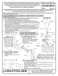
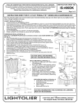
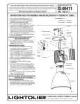
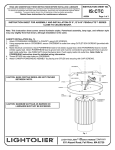
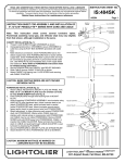
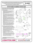
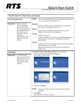
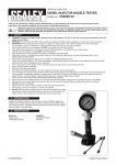
READ AND UNDERSTAND THESE INSTRUCTIONS BEFORE INSTALLING LUMINAIRE
INSTRUCTION SHEET NO.
This luminaire is intended for installation in accordance with the National Electrical Code and local regulations.
To assure full compliance with local codes and regulations, check with your local electrical inspector before
installation. To prevent electric shock, turn off electricity at fuse box before proceeding.
Retain these instructions for maintenance reference.
IS:4091216
A0304
Page 1 of 1
INSTRUCTION SHEET FOR 9”,12”&16” PENDALYTE™ POWERHEAD
Note: This instruction sheet covers several luminaire styles. Powerhead assembly, lamp type, and reflector style may vary slightly from that
shown, although installation is the same.
CONNECT TO APPROPRATE VOLTAGE
To wire POWERHEAD to suspension kit (Standard, Stem, and Deco suspension kits sold
separately) follow instructions enclosed with individual suspension kit and connect as follows:
Using wire nuts (local hardware item) connect black lead to hot (black) power lead, connect
white lead to neutral (white) power lead, connect green/bare leads to ground (green) lead.
METAL HALIDE FIXTURES: refer to wiring diagram in fig. 1.
277V
240V
208V
120V
BLACK
POWERCORD
CAUTION: MAXIMUM WATTAGE AS MARKED ON LUMINAIRE MUST NOT BE
EXCEEDED.
COMMON
WHITE
GROUND
GROUND
HID BALLAST
Fig. 1
9”ALUMINUM REFLECTOR INSTALLATION
1.
2.
3.
POWERHEAD
Locate 8-32 SCREWS, (supplied with POWERHEAD).
Align holes in ALUMINUM REFLECTOR with threaded holes in SPACER COLLAR. (Fig. 2)
Install 8-32 SCREWS and tighten evenly.
SPACER COLLAR
9” GLASS SHADE INSTALLATION
CAUTION:
Wear safety glasses. Glass is fragile. Handle with care. Broken glass may pose
a personal safety hazard.
NOTE: Natural oils and soil may discolor and stain glass finish. Wearing clean cotton gloves is recommended.
1.
2.
3.
Locate RETAINER CUP, GASKET STRIPS and 8-32 SCREWS, (supplied with POWERHEAD).
Thoroughly clean aluminum retainer cup to insure good adhesion of GASKET STRIPS. Peel off
ADHESIVE BACKING and apply GASKET STRIPS to retainer, equally spaced, as shown. (Fig. 3)
Support glass shade in place, align evenly with extruded collar, and align RETAINER CUP with
THREADED INSERTS in socket plate.
Install 8-32 SCREWS and tighten evenly to compress gasket strips.
ALUMINUM REFLECTOR
8-32
SCREWS
Fig. 2
12”&16” REFLECTOR/REFRACTOR INSTALLATION
POWERHEAD
1.
2.
3.
THREADED
INSERT
4.
GLASS
SHADE
Slide COLLAR up extruded NECK.
Peel off backing of FOAM GASKET and adhere to TABS on SOCKET MOUNT PLATE. (Fig. 4)
Tip Reflector/Refractor over SOCKET MOUNT PLATE and allow Reflector/Refractor to rest on
FOAM GASKET.
To secure Reflector/Refractor align SLOT in
POWERHEAD
COLLAR over PINS and slide COLLAR down
NECK. Twist COLLAR counter-clockwise allowing
PIN to rest in NOTCH.
NOTCH
SLOT
12” REFRACTOR SUPPORT
ADHESIVE
BACKING
GASKET
STRIPS
RETAINER CUP
8-32
SCREWS
Fig. 3
COLLAR
CAUTION: 12” HID units with Acrylic Refractor
must have REFRACTOR SUPPORT PLATE
installed.
REFRACTOR SUPPORT PLATE and SUPPORT
PLATE SCREWS ARE supplied with all 12” HID
units.
1. Install Acrylic Refractor per instructions above.
2. Align REFRACTOR SUPPORT PLATE over
SOCKET MOUNT PLATE. (Fig. 4)
3. Secure REFRACTOR SUPPORT PLATE with
SUPPORT PLATE SCREWS.
NECK
FOAM
GASKET
PIN
SOCKET
MOUNT
PLATE
TAB
REFRACTOR
SUPPORT
PLATE
SUPPORT
PLATE
SCREWS
Fig. 4
a
COMPANY
631 Airport Road, Fall River, MA 02720