1
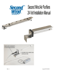
Owner’s Manual
Standard Warranty
Light & Motion provides a limited warranty to the original purchaser against all defects in
original workmanship and material, under normal use and service, for one year from the
date of purchase, with the following exceptions: Lamps are warranted for 30 days, batteries
are warranteed for 90 days, and battery chargers are warranteed for use only in the US and
Canada. Using a battery charger in conjunction with a voltage converter is NOT considered
normal use and chargers are not warranteed under such conditions. Light & Motion will not
be liable for any further loss, damages, or expenses, including incidental or
consequential damages directly or indirectly arising from the sale or use of this product.
Products not manufactured by Light & Motion, such as strobes and strobe arms, are not covered under the Light& Motion warranty. These products are covered by the Terms and
Conditions set forth by their respective manufacture.
TITAN D100
Fault Free Warranty (Optional)
For 24 months from warranty purchase date this product is warranteed against any physical
damage or harm, from any cause, regardless of the fault of purchaser, limited only by
intentional damage. During the Fault-Free Warranty period, any damage to or defects in
this product will be repaired and any adjustments needed for the product to conform full to
factory prescribed standards will be made, without charge. At our option, the product will
be replaced without charge (but only once during the Fault-Free Warranty period, and only
if the serial number is recognizable). If the product is replaced under the Fault-Free
Warranty due to customer negligence or internal disruption of the product, the replacement
product will be covered only by the Extended Warranty (up to the end of the original FaultFree Warranty period). Also included in the Fault-Free Warranty is one Light & Motion
Annual Service.
These warranties extend only to the original purchaser through Light & Motion or an
authorized dealer.
The Fault-Free Warranty does not cover the following:
Loss of product as the result of theft, misplacement, or other cause. Accessories, monitors,
accessories lenses and pointer lights, chargers, parts such as lamps, O-rings, and batteries
that are wear items. Damage due to tampering or repair by a non-authorized shop or
person. Import duties, customs clearance fees, and general expenses involving shipping to
Light & Motion. Light & Motion reserves the right to choose the return shipping method of
warranted products. Expedited shipping charges are purchaser's responsibility.
The expressed warranty set forth herein is in lieu of all other warranties expressed or
implied, including without limitation any warranties of merchantability or fitness for a
particular purpose, and all such warranties are hereby disclaimed and excluded by the
manufacturer. Repair or replacement of defective items as provided above is the sole and
exclusive remedy provided hereunder. Light & Motion will not be liable for any further loss,
damages, or expenses, including incidental or consequential damages directly or indirectly
arising from the sale or use of this product.
The Titan D100 Fault Free Warranty is $300. Contact your Light & Motion reseller
or Light & Motion directly to activate your Fault Free Warranty.
www.uwimaging.com
Welcome
Table of Contents
Congratulations on your purchase of the Titan D100 digital SLR housing.
Getting Started . . . . . . . . . . . . . . . . . . . . . . . . . . . . . . . . . . . . . . . . . . . . . . . . . . . . . . 5
Please inspect the packaging of your product to verify that there was no damage during
shipping.
First Time Use . . . . . . . . . . . . . . . . . . . . . . . . . . . . . . . . . . . . . . . . . . . . . . . . . . . . . . . 6
Camera Preparation . . . . . . . . . . . . . . . . . . . . . . . . . . . . . . . . . . . . . . . . . . . . . . . . . . 6
If you are not familiar with your camera’s features, please take time to become familiar
with the camera before you proceed in this manual. This manual assumes you have a
working knowledge of your camera and will only cover operational procedures relative
to the underwater housing.
Periodically refer to the website for instruction revisions.
http://www.uwimaging.com
Installing Battery Board . . . . . . . . . . . . . . . . . . . . . . . . . . . . . . . . . . . . . . . . . . . . . . . . 6
Installing the D100 . . . . . . . . . . . . . . . . . . . . . . . . . . . . . . . . . . . . . . . . . . . . . . . . . . . 8
Titan D100 Controls . . . . . . . . . . . . . . . . . . . . . . . . . . . . . . . . . . . . . . . . . . . . . . . . . 10
Attaching Strobes . . . . . . . . . . . . . . . . . . . . . . . . . . . . . . . . . . . . . . . . . . . . . . . . . . . 14
Caution - Caution - Caution - Caution - Caution
Installing Bulkheads . . . . . . . . . . . . . . . . . . . . . . . . . . . . . . . . . . . . . . . . . . . . . . . . . . 14
Attaching Sync Cables to Titan . . . . . . . . . . . . . . . . . . . . . . . . . . . . . . . . . . . . . . . . . 14
We hope you have a wonderful underwater experience with Light & Motion equipment.
To increase your enjoyment and the life span of your new gear please take an extra
minute to review these general recommendations.
Pre-Dive Checklist . . . . . . . . . . . . . . . . . . . . . . . . . . . . . . . . . . . . . . . . . . . . . . . . . . . 15
ROC and Focus Controls . . . . . . . . . . . . . . . . . . . . . . . . . . . . . . . . . . . . . . . . . . . . . 15
•
•
•
•
•
Check the operation of all your equipment several weeks prior to your trip. If maintenance or repair is necessary, then time is available for both shipping and repair scheduling.
Never transport or ship the housing with the camera inside.This may damage your camera.
Never leave your housing in the rinse bucket, it may be damaged by other equipment.
When removing the camera from the housing after a dive, do so in a dry controlled environment away from other SCUBA related equipment. This prevents water from other
equipment or water from another diver accidentally entering the housing.
If a product is flooded, immediately rinse it with fresh water. Most parts will be salvageable if not corroded by salt water.
Changing D100 Lenses . . . . . . . . . . . . . . . . . . . . . . . . . . . . . . . . . . . . . . . . . . . . . . . 20
Attaching Light & Motion Lens Gears . . . . . . . . . . . . . . . . . . . . . . . . . . . . . . . . . . . . 20
Attaching and Removing Ports and Conversion Rings . . . . . . . . . . . . . . . . . . . . . . . . 20
Installing optional Mod Lights . . . . . . . . . . . . . . . . . . . . . . . . . . . . . . . . . . . . . . . . . . 22
Replacing ROC Handle Batteries . . . . . . . . . . . . . . . . . . . . . . . . . . . . . . . . . . . . . . . . 22
Replacing Handle Thread Rings . . . . . . . . . . . . . . . . . . . . . . . . . . . . . . . . . . . . . . . . . 24
Moisture Alarm . . . . . . . . . . . . . . . . . . . . . . . . . . . . . . . . . . . . . . . . . . . . . . . . . . . . 24s
After Diving Care . . . . . . . . . . . . . . . . . . . . . . . . . . . . . . . . . . . . . . . . . . . . . . . . . . . 25
O-ring Care and Maintenance . . . . . . . . . . . . . . . . . . . . . . . . . . . . . . . . . . . . . . . . . . 25
Titan D100 Accessories . . . . . . . . . . . . . . . . . . . . . . . . . . . . . . . . . . . . . . . . . . . . . . . .26
Returning Products for Care . . . . . . . . . . . . . . . . . . . . . . . . . . . . . . . . . . . . . . . . . . . 27
Contact Light & Motion . . . . . . . . . . . . . . . . . . . . . . . . . . . . . . . . . . . . . . . . . . . . . . . 27
Getting Started
First Time Use
Illustrated below are the locations of Titan’s features, ports, and functions. Take time to
familiarize yourself with the housing.
All Light and Motion housings are pressure tested prior to shipping. However,
there could be unseen damage from shipping. A test dive without the camera in
the housing is highly recommended.
1.
2.
3.
4.
After the initial dive with just the housing, make the following checks.
Dry off housing exterior.
Remove the Rear Plate and visually inspect for moisture.
Reach inside the housing and trace a finger around all view ports and mating surfaces.
If any water is detected, contact the housing reseller or the Light & Motion service
department.
Camera Preparation
TITAN
1.
2.
3.
4.
5.
6.
7.
8.
Remove the camera’s strap from the camera.
Attach the desired lens for use.
Remove the camera’s lens cap.
Remove the rubber accessory cap from the bottom of the camera (Fig. 1). The Titan’s
camera tray has a pocket for the cap to be stored when the camera is on the tray (Fig3).
Remove the hotshoe cover.
Place battery board onto camera battery (Read next section “Battery Board”).
Install a fully charged EN-EL3 camera battery.
Install a media card.We recommend at least a 1GB size card.
Battery Board
The Titan D100’s Battery Board is the component that allows the Titan’s “Focus” button
(located on the right handle) to function. No other housing functions are affected. If you
choose not to use the Battery Board, you can use the mechanical shutter for auto-focus.
You received two battery boards with your Titan D100 housing. One is a spare and can
be stored inside the Titan’s rear plate (Fig. 7 & 8).
1.
2.
Remove the non-stick paper covering the Battery Board’s adhesive side.
Orient the Battery Board to the contours of the battery and press into place (Fig 6).
The Battery Board adhesive is meant to be strong enough to hold the board onto the
battery, yet easy to remove when attaching the battery to a charger.
Eventually the Battery Board’s adhesive will exhaust. When this occurs, you can simply
“drop-in” the board into the camera’s battery compartment.You may need to guide the
board into place.
You can also contact Light & Motion to purchase replacement battery boards.
Replacment Battery Boards are p/n # 825-0188.
Installing the D100
1.
2.
3.
(Fig. 1)
4.
5.
6.
(Fig. 2)
7.
8.
9.
Battery Board
(Fig. 3)
(Fig. 4)
Remove the rear plate by holding both latch locks in and simultaneously rotating both
latches down and rearward of the housing body (Fig. 9).
Remove the camera tray. Press the Camera Tray Latch to the left and pull the tray
backward out of the housing (Fig 10).
Remove the accessory cap from the bottom of the camera. Place the cap in the retaining
pocket in the camera tray for easy retrival.
Place the battery board onto the camera battery if you haven’t already done so.
Install the battery into the camera.
Place the camera’s focus selector in the C position (Fig. 11).
Rotate the focus selector gears on the camera tray so the gear opening is oriented at the
six O’clock position (Fig 12.).
Place the D100 onto the camera tray, align the tripod screw and accessory jack, and
tighten tripod screw into camera.Tighten the screw with a coin.
Rotate the focus selector gears to ensure they engage properly on the camera. If the
gears are not operating correctly, remove the camera from the tray, realign the gear with
the camera’s lever and reattach the camera to the tray.
Attach hotshoe cable from tray into hotshoe mount of camera (Fig 13). Guide the cable
on the right side of the camera, away from the focus selector gears.
Test the connection between the camera and the ROC system by turning the camera on.
The ROC LED panel should illuminate with a LED in each power bank and the two green
LED back lights.
If no LEDs illuminate, re-seat the camera onto the camera tray. Visually check that the
camera is seated flush with entire camera tray.Turn on the camera to check connectivity.
(Fig. 5)
(Fig. 6)
10. Pull the Titan’s Mode Dial up. Pull and rotate the Focus/Zoom gear to the neutral position
(Fig 14).
11. Rotate the Titan’s Focus Mode selector lever to the C position (lever down Fig. 15).
12. Install the camera tray. Guide the camera tray onto the two tray rails. Continue to push
until the Camera Tray Latch engages the guide pin and locks the tray (Fig 16).
13. Turn the housing Mode Dial to match the position of the camera and press down.
14. Check the alignment and operation of all handle functions, housing controls, the
focus/zoom gear alignment, and the MSC Lever.
15. Turn the Metering Mode Selector on the Rear Plate to match the camera’s.
16. Check both O-rings on the Titan’s Rear Plate and check the sealing surface on the Titan
hull, then replace the Rear Plate.
17. When sealing the Rear Plate, rotate both latchs evenly.
18. Check all handle and housing functions.
It is very important that the Rear Plate draws in evenly and that the O-rings
seat and seal correctly. Check sealing surface on top and bottom to confirm
proper seal.
(Fig. 7)
(Fig. 8)
Titan D100 Controls
Top Controls
Mode Dial (Fig 17): Accesses the camera’s Mode Dial.
Use the Mode Dial to select camera’s exposure mode.
Use the Mode Dial to select the following settings:
ISO - White Balance - Image Size - Image Quality - AF Area Mode
(Fig. 9)
(Fig. 10)
On Dial (Fig. 18):Turns the camera on.
To turn the camera on, turn the On Dial counter-clockwise until it stops.
Then press the On Dial down and turn clockwise.
Note:The camera can’t be turn off while in the housing.
Back Light button (Fig 18): Illuminates the LCD data screen.
The Back Light button is also used in combination with the Format Button
(located on the Rear Plate) to format the media card when the camera is
in the housing.
Exposure Compensation (Fig 18): Accesses camera’s exposure compenstation features.
Rear Plate Controls
(Fig. 11)
(Fig. 12)
Metering Selector Lever (Fig. 19): Selects camera metering method.
Arrow Buttons (Fig. 20): Selects area focus, menu and navigates images during playback.
Trash Can button (Fig. 21): Deletes images during playback.
BKT button (Fig. 22): Access camera’s bracketing features.
Format (Fig. 22): Use with Back Light button to format media card.
Monitor button (Fig. 23): Switches camera to playback mode.
(Fig. 13)
(Fig. 14)
Menu button (Fig. 23): Activates camera’s menu.
Thumbnail button (Fig. 24): Changes playback image size.
Enter Button (Fig. 24): Confirms menu selections.
Left Side Controls
Focus / Zoom Dial: Engages the lens manual focus or zoom ring (Fig 25).
Focus / Zoom Neutral Lock: Disengages focus gear when using auto focus (Fig 26).
(Fig. 15)
(Fig.16)
Front Controls
Shutter Lever: Accesses the camera’s shutter button (Fig. 27).
The Shutter Lever also activates the camera’s auto focus when depressed
half way.When depressed fully, the camera will take a photo.
Focus Mode Selector (Fig. 28): Selects camera’s focus mode.
Left Smart Grip (Fig. 29)
(Fig. 17)
(Fig. 18)
Main + button: Increases shutter speed in M and S shooting modes.
Main - button: Decreases shutter speed in M and S shooting modes.
The Main + / - buttons perform all main command dial functions.
(Fig. 19)
(Fig. 20)
L ~ R OFF: Selects strobe control mode and deactivates strobes.
Strobe power can be controlled independently from the respective side handle or
strobe power can be controlled together from either handle.
To control strobes independently, press the button until the ROC LEDs blink separately.
Strobe power level is controlled by the handle on the same side.
To adjust strobe power together, press the button until both LEDs blink together. Either
handle then controls power level for both strobes.
To deactivate strobes, press and hold button until Strobe OFF LEDs illuminate.
To reactivate strobes, press and release button.
~ + and~
- buttons: Left strobe increase or decrease power buttons.
Right Smart Grip (Fig. 30)
Sub + button: Increases f/stop in M and A shooting modes.
Sub - button: decreases f/stop in M and A shooting modes.
(Fig. 21)
(Fig. 22)
The Sub + / - buttons perform all sub command dial functions.
~ + and ~ - buttons: Right strobe increase or decrease power buttons.
Focus button: Pressing this button is just like pressing the shutter button half way.
Activates electronic auto focus (half shutter).
Press and hold the Focus button to keep the camera’s focus locked.
While holding the Focus button down, pull the shutter release to take a photo.
Focus button will not function if the Battery Board is not installed.
Also see page 18 to use the AEL/AFL feature of this button.
(Fig. 23)
(Fig. 24)
Attaching Strobes
The Titan housing is supplied with two 1” Base Ball Mounts (Fig. 31). Most ball style
clamps for strobe arms can readily attach to these base mounts (Fig. 32).
Installing Bulkheads
1.
(Fig. 25)
2.
3.
(Fig. 26)
4.
5.
6.
7.
8.
9.
Remove bulkhead cap by inserting a coin into the slot in the cap and turning
counter clock wise.
Loosen retaining screw and free bulkhead cables (Fig 34).
Use a 3/4” wrench to unscrew the bulkhead from the Titan. Carefully pull bulkhead and
wires through port in Titan.
Check the O-ring and sealing surface of the bulkhead.
Insert the wires of the new bulkhead through the port of the Titan.
Hand tighten bulkhead into port.
Tighten the bulkhead with a 3/4” wrench.
Insert the wire plug from the bulkhead in to the connector on the circuit board.
Guide bulkhead wires under the retaining bracket and tighten screw.
If installed correctly, the bulkheads should be flush to top of housing.
Attaching Sync Cables to Titan
(Fig. 27)
Nikonos Style
(Fig. 28)
1.
SUB
+
+
+
2.
3.
SUB
L
R
FOCUS
Align the index mark on the sync cord with the guide mark on the Titan bulkhead. Push
the sync cord into the bulkhead connector.
Turn the threaded connector until it is seated firmly into the bulkhead.
If the sync cable has a locking ring, turn the locking ring until it is hand tight and secured
the sync cable.
Wetmate Style
OFF
(Fig. 29)
(Fig. 30)
1.
1.
2.
Lightly apply silicon grease to Wetmate sync cable contacts.
Align all five pins of the Wetmate Sync cable with the five pin receptor of the bulkhead.
Push firmly until the pins are firmly seated in the bulkhead (Fig 18).
If you decide to dive without strobes attached, disable the strobe signal by using the
L ~ R Strobe Off function.
Wetmate sync cords and bulkhead performance is designed to be impervious to water.
To ensure long-term performance, flush with fresh water and dry contacts if exposed to
salt water. Apply silicone grease to Wetmate contacts
(Fig. 31)
(Fig. 32)
Pre-Dive Checklist
1.
2.
3.
4.
5.
6.
Programming ROC
Install media card into camera.We recommend at least a 1GB card.
Install a fully charged EN-EL3 battery with battery board into the camera.
Verify operation of all controls and gears.
Turn on the strobes and take a test picture.
Check the housing lens and/or conversion ring for proper seal(s).
Check that the rear plate o-rings are seated correctly and that the rear latches are in the
closed and locked position.
ROC and Focus Controls
ROC - Defined
ROC can only function successfully by knowing the type of strobe(s) being used. It is
necessary to program ROC prior to using the Titan underwater. Once ROC is
programmed it will never have to be reprogrammed unless a different model strobe is
used. ROC will retain its programming even when the ROC is in the off status.
ROC’s default strobe profile is for Sea & Sea YS-90DX/90/60/50. If you are using different
strobe(s) use the following procedure to change the ROC strobe profile.
1.
2.
ROC is an innovative strobe and camera control interface built into the Titan Housing.
ROC allows the underwater photographer to obtain up to 12 manual power levels on
most TTL compatible strobes. ROC’s strobe power control spans from full power to -7
f/stops or ROC can disable the strobes from firing. This gives the digital underwater
photographer unprecedented flexibility and convenience when lighting subjects. Up to
two strobes can be connected to the Titan via Nikonos style or Wetlink style bulkheads.
ROC allows the power levels for each strobe to be controlled independently or together.
Use the L ~ R Strobe button to select and program both strobes simultaneously or to
program the left and right strobes independently (Fig 37). If both LED are moving, both
strobes are being programmed. If only one LED is moving, only one strobe is being
programmed. The Left and right LED banks program the left and right strobes
respectively.
3.
In addition to the unique strobe control, the Titan D100 handles also offers electronic
Auto-Focus, Auto Focus Lock, Area Focus Selection, and control of Command Dials.
ROC - Status
ROC is ON when the power level LEDs are displayed.
ROC is in STAND-BY after being idle for 60 seconds and power level LEDs are not displayed. ROC is ready to take a photograph, this is just a power saving mode.To check the
power level of the strobes when ROC is in Stand-By mode, press any of the strobe buttons on either handle. This will not alter the ROC power settings, but will return ROC
to an ON status.
ROC is powered by the camera’s battery.When the camera is off, ROC is off.
Press and hold the ~ + and ~ - buttons on the left or right handle (Fig. 35) until the
REC LEDs begin to pulse.When the LEDs are pulsating, ROC is in programming mode.
Press the ~ + or ~ - buttons on the ROC handles (Fig. 36) to position the LEDs in
the appropriate LED setting for your strobes. Refer the chart in Fig. 38 to determine
which LED setting is for which strobe.
When the LEDs are positioned in the appropriate setting, press the and hold +/- buttons
on either handle to save the strobe profile (Fig 39). LEDs will then be a steady light
indicating current strobe power.
During the programming process, if programming is idle for 60 seconds ROC will record
the strobe profile of the current LED position and enter stand-by mode.
ROC Stand-by and Time Out schedule
ROC is fully active when the LEDs are showing strobe power levels.
After 60 seconds of inactivity ROC enters stand-by mode. ROC is still active but turns
off the LEDs to conserve battery power. ROC will return to the active mode by pressing
any button from either ROC handle or the mechanical shutter.
Using ROC for strobe control
The default strobe control settings for ROC has the strobes being controlled
independently from the respective handle. ROC will revert to this setting every time it
enters the OFF state or when the camera is removed from the tray and ROC loses
power. ROC will always retain the last programmed strobe profile even when power is
removed.
(Fig. 33)
1.
2.
(Fig. 34)
+
+
3.
L
R
L
OFF
Press together and hold
to enter programming mode.
(Fig. 35)
R
OFF
(Fig. 36)
+
L
R
OFF
Press strobe select button to adjust
LEDs together or independently.
(Fig. 37)
To deactivate the strobe from firing, press and hold the L ~ R Strobe button on the left
handle until the Strobe Off LEDs illuminate (Fig. 42). Press and release the L ~ R button
to re-activate strobes.
Press either button to move
ROC LED position.
F
–
-1
–
-2
–
-3
–
-4
-5
-6
-7
Using ROC for AE-L / AF-L
=
=
=
=
=
=
=
=
=
=
=
=
Empty
Ikelite 400
Ikelite 200
Ikelite DS-125
Ikelite 100
Ikelite DS-50/50
Nikonos SB-105
Nikonos SB-104
Sea & Sea YS-350/300
Sea & Sea YS-120
Sea & Sea YS-90DX/90/60/50
Sea & Sea YS-30
The default setting for the Focus button is half-shutter. Pressing this button is the same
as pressing the camera’s shutter release half-way. The Focus button can also be
reporogrammed to be the camera’s AE-L / AF-L button.While in this mode pressing the
handle’s Focus button is the same as pressing the AE-L / AF-L button on the camera.
This is a two step process and will change the default, half shutter, function of the Focus
button to the AE-L / AF-L function.
1.
(Fig. 38)
2.
Press and hold both the Sub + and Strobe + on the right handle (Fig. 43).
The handle LED should blink 4 times indicating the Focus button switching to Focus lock
function (Fig. 44).
Enter the camera’s menu and select the CSM menu. In the CSM menu scroll to sub-menu
14 and enter. In this sub-menu change the setting to “AF ON” (Fig 45) or whichever
optoin you prefer.
To use the auto focus lock, press the Focus button. The camera will auto focus and
continue to refocus as long as the button is held down. When the camera is focused at
the appropriate distance, release the Focus button.
+
L
R
OFF
Press together and hold
to save strobe profile.
(Fig. 39)
Turn strobe(s) on and in the TTL position.
Press the +/- buttons on the respective handles to adjust strobe power (Fig. 40).
To adjust strobe power levels together, press the L/R Strobe button and watch for power
LEDs to blink together. Then press the +/- button from either handle to adjust strobe
power for both strobes (Fig. 41).
To return to adjusting the strobe power levels independently, press the L/R Strobe button
and watch for the power LEDs to blink separately. Then press the +/- button from the
respective handle to adjust that side strobe power.
Press the + button to increase the strobe’s power or the - button to decrease the
strobe’s power.
The camera will keep focus locked at the same distance until the Focus button is pressed
again.Then the camera will readjust the focus distance.
To return the Focus button to half-shutter return the menu focus setting to its prior
setting and press the Sub + and Strobe + buttons until the handle LED blinks twice.
Using ROC for area focus select
+
+
This feature requires the Focus button to be set up in the AE-L / AF-L function outlined
in the previous section.
L
R
L
OFF
1.
2.
R
OFF
Press these buttons to
increase or decrease strobe power.
(Fig. 40)
Press strobe select button to adjust
strobes together or independently.
3.
(Fig. 41)
Press and hold the Focus button (Fig. 46).
While holding the Focus button press the Sub - button (Fig. 47).
You will see the focus area highlighted in the view finder.
Continue holding the Focus button and pressing the Sub - button to scroll through the
focus zones of the camera.
Changing D100 Lenses
The Titan D100 has a lens release mechanism that allows you to change camera lenses
with the camera inside the Titan housing.
SUB
+
+
+
SUB
L
R
1.
2.
3.
FOCUS
OFF
Press and hold to
deactiveate strobe(s).
(Fig. 42)
Press and hold both buttons
to enter “AEL-AFL” mode.
Remove the Titan port.
Press the lens release lever that extends to the camera’s lens release button.
Continue holding the lever and turn the lens clockwise to remove it.
Attaching Light & Motion Ports / Conversion Rings
(Fig. 43)
To Install Lens / Conversion Ring
1.
2.
3.
4.
SUB
+
+
SUB
Inspect O-rings for serviceability.
Align bayonet details on lens/ring to bayonet details on housing.
Press lens/ring into housing and ensure the entire mating surfaces are flush (Fig. 49).
Rotate clockwise until locking pin engages (Fig. 50).
To Remove Lens / Conversion Ring
FOCUS
1.
2.
3.
LED will blink four times when
switching to AEL-AFL mode.
(Fig. 44)
Slide locking pin away from lens/ring (Fig 48).
Rotate lens/ring counter clockwise until port/ring stops.
Pull away from housing.
(Fig. 45)
Attaching Light & Motion Lens gears
Refer to the instructions that were packaged with your gear set for gear instalation.
SUB
+
SUB
+
+
SUB
FOCUS
To change focus zones: First
Press and hold the Focus button.
(Fig. 46)
+
SUB
FOCUS
Then press the “Sub -”
button to change focus zones.
(Fig. 47)
Light & Motion ports and gears are made for Nikon Lenses. The following lenses are
suported; 14mm, 16mm, 18mm, 20mm, 24mm, 17-35mm, 60mm, 105mm and 12-24 DX.
Installing Mod Light
Installing Sunray Mod Light (Optional)
1.
2.
7.
Identify the appropriate parts in the Titan mounting kit included with the Mod Light.
Titan Kit includes the following.
Hex screw, split washer, metal washer, 1/2” hexogonal base piece, and hex key.
Place the hex screw through the split washer and metal washer.
Place both the hex screw and both metal washers together through the round end of the
base piece (Fig. 51).
Place the base assembly over the accessory hole of the Titan.
Orient the base piece so the hexogonal shape of the base piece matches the hexogonal
detail of the Titan and so the hex screw rests on top of the accessory mount.
Tighten the entire assembly by tightening the hex screw into the Tetra’s accessory hole
8.
Then snap Mod Light and arm assembly on the base (Fig. 52).
3.
4.
(Fig. 48)
(Fig. 49)
5.
6.
Installing the Pointer Light (Optional)
1.
2.
(Fig. 50)
(Fig. 51)
3.
4.
5.
6.
Identify the appropriate parts in the Titan Modeling Light Kit.
Kit includes the following.
Hex screw, 1/4” base piece, Infinity arm, modeling light and light bracket.
Position the base piece details on the detail of the Titan’s accessory hole.
Place the hex screw through the base piece and tighten with hex key (Fig. 53).
Place Infinity arm with holder over the base piece and press firmly down until the Infinity
arm snaps into position (Fig. 54).
Place Modeling light in to light bracket.
Replacing ROC Handle Batteries
The battery life of your ROC Handles will vary depending on usage and technique. But
eventually the handle batteries will exhaust.
The handles will signal when the battery power is becoming low. The handle LED will
blink eight times after any button is pressed.This is a signal to change the batteries prior
to the next dive.
(Fig. 52)
Replacing the handle batteries is an easy procedure. However, pay special attention to the
wear of the O-ring and to the orientation of the batteries.You will need to purchase the
ROC Handle O-ring battery kit (P/N 802-0117)
(Fig. 53)
1.
2.
3.
4.
5.
6.
7.
Using a 3/32 hex key, remove the two hex screws on the back of the handle (Fig. 55).
Remove the Handle Cap from the handle assembly.
Remove old batteries from handle board.
Install new 1/3 N batteries into the handle board (Fig. 56)
Service Handle Cap O-ring or replace with a new O-ring.
Press the Handle Cap into the handle assembly so O-ring seals evenly.
Replace both hex screws in Handle Cap and tighten using hex key.
ROC Handle O-ring and Battery Kit (part # 802-0117)
Kit contains one O-ring, 3/32 hex key, and two batteries for one ROC Handle.
(Fig. 54)
Replacing Handle Thread Rings
The Handle Thread Rings that attach the ROC handles (Fig. 57) to the Titan housing are
designed to absorb shock should the Titan be dropped or fall. If the Handle Thread Rings
experience extreme pressure, they will break and minimize potential damage to the Titan.
Contact your dealer for a Handle Thread Ring Replacement Kit (p/n 802-0147) or
contact the Light & Motion Service department at 831-645-1572.
Follow the steps below to replace the Handle Thread Ring and reattach the handle.
(Fig. 55)
(Fig. 56)
1.
2.
3.
4.
5.
Place new Handle Thread Ring over the handle dock of the Titan
Install the snap ring over the handle dock to retain the Handle Thread Ring (Fig. 58).
Align the handle with the opening of the thread ring.
Hand turn the thread ring counter-clockwise until the handle begins to tighten.
Use the supplied wrench to finish tightening the handle.
Handle Thread Ring Replacement Kit contains:
2 - Handle Thread Ring, 2 - snap rings and 1 - spanner wrench.
Moisture Alarm
(Fig. 57)
(Fig. 58)
The Titan’s moisture alarm (Fig. 59) gives a visual indication that water has been detected inside of the housing.
The two metal contacts are located inside the Titan, in the front and slightly to the left
(Fig. 59). If water touches these contacts the ROC LED panel will display an array of lights.
Immediately move the Titan to a dry location.
The moisture alarm will continue it’s display of lights until it no longer detects water and
one of the handle buttons is pressed.
If water touches the Moisture Alarm contact, clean throughly and check for corrosion.
(Fig. 59)
After Diving Care
1.
2.
Immediately submerge the housing in fresh water. While in fresh water, work the dials,
levers and all the buttons, to work any remaining salt water out of the housing.
Remove housing from rinse tank and then simply towel dry.
Titan D100 Accessories
Titan D100 Fault Free Warranty . . . . . . . . . . . . . . .905-0200
Tetra Wetlink Sync Cord (Sea & Sea only) . . . . . . .854-0044
Don’t abandon your Titan D100 in the rinse tank!!! It’s not uncommon for
another housing or camera to be carelessly dropped into the rinse tank.
Other equipment falling onto your Titan D100 can scratch ports or damage
the housing body.
O-ring Care and Maintenance
O-rings are the critical component that keeps water out of the housing. Routinely
inspect o-rings and replace at least once a year. If your o-rings are damaged, contact
the Light & Motion service department for an o-ring replacement kit.
Titian D100 Custom Travel Case . . . . . . . . . . . . . . .775-0019
Sunray Mod Light . . . . . . . . . . . . . . . . . . . . . . . . . .850-0049
Titan Pointer Light . . . . . . . . . . . . . . . . . . . . . . . . . .854-0051
Titan D100 Electronics Replacment Kit . . . . . . . . .854-0152
Titan D100 Body Cap . . . . . . . . . . . . . . . . . . . . . . . .854-0148
Follow these steps for proper o-ring care.
Titan D100 Neoprene Dome Port Cover . . . . . . . .854-0149
1)
2)
3)
The sealing system used on the rear plate incorporates two o-rings.This is the most critical area of the housing for maintenance and should be inspected before every dive.
Make sure the rear plate o-rings and the mating surface on the inside of the main housing are clean from grit, hair, lint and anything that could potentially breach the o-ring seal.
After frequent diving or if o-rings appear dirty, remove o-rings and clean the grooves.To
remove o-rings, use finger pressure or the rounded edge of a plastic card to lift the oring out of the groove.
Never use a metal object to remove an o-ring. It will cause damage to the o-ring and mating surface.
4)
5)
6)
7)
8)
To check o-rings for damage, place the o-ring between the index finger and thumb.Then
pull the o-ring through your fingers, feeling for any debris or wear.
If o-rings are dirty, it is best to replace them.Washing dirty o-rings with soap and water
is not recommended. Soap breaks down the lubricants and will compromise the integrity of the seal.
Properly greased o-rings will help maintain sealing integrity and minimize o-ring degradation. Use enough grease to lubricate the o-ring thoroughly, but not so much that it will
attract additional debris.
Clean the groove with a lint free swab or the folded edge of a paper towel.
Return O-ring to respective groove.
Titan D100 O-ring Replacement Kit part # 854-0129, includes two o-rings for the Rear
Plate, two O-rings for a port and 1/4 oz. of O-ring grease.
Titan D100 O-ring Kit . . . . . . . . . . . . . . . . . . . . . . .854-0129
Smart Grip Battery and O-ring Kit . . . . . . . . . . . . .854-0117
Handle Thread Ring Replacement Kit . . . . . . . . . .854-0147
Handle Strobe Base Mounts . . . . . . . . . . . . . . . . . .854-0104
Returning Products for Care
We highly recommend a factory annual service to maintain proper operation of your Titan Housing
1)
2)
Before returning your Light & Motion product for care, please call or email our service
department for a RMA number.
Ship your product pre-paid freight with the RMA number printed on the outside of the
box. It is recommended that you keep your shipper’s tracking number until the product
is returned to you.
Warning: Do not ship your camera inside the housing. Shipping
companies may drop your system from up to three feet which
could damage your camera.
Contact Light and Motion
Sales Department:
831-645-1525 • Fax 831-375-2517
Service Department:
831-645-1572 • Fax 831-375-2517
Mail:
Light & Motion
300 Cannery Row
Monterey, CA 93940
E-mail:
[email protected]
European Service Center
FEP Ltd.
Attn: Steve Mawle
Aston House
Heimdon Rd.
Sulgrave
OX17-2SQ
England
1295 768686 (ph.)
1295 768446 (fax)
[email protected]
www.fep.co.uk
World Wide Web:
www.uwimaging.com
300 Cannery Row • Monterey, CA 93940
(831) 645-1525 • Fax (831) 375-2517
www.uwimaging.com
905-0208-B