1
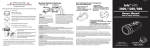
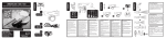
Bluefin HC3 Owner’s Manual
For the Sony HDR-HC3 camcorder
www.uwimaging.com
Welcome
Congratulations on your purchase of the Bluefin underwater video housing.
Please inspect the packaging of your product to verify that there was no damage
during shipping.
If you are not familiar with your camcorder’s features, please take time to become
familiar with the camcorder before you proceed in this manual.This manual assumes
you have a working knowledge of your camcorder and will only cover operational
procedures relative to the underwater housing.
The term “Push” when referenced in this manual means to press and release in one
motion. If a function requires a button to be continually held, the manual will read,
“press and hold.”
Periodically refer to the Light & Motion website for instruction revisions,
www.uwimaging.com.
Caution - Caution - Caution
We hope you have a wonderful underwater experience with Light & Motion
equipment. To increase your enjoyment and the life span of your equipment please
take an extra minute to review common errors which will result in equipment
damage or destruction.
•
•
•
•
•
•
Always remove batteries from battery pods before storage or travel.
Failure to do so may result in inadvertent ignition of lighting system and
possible heat or fire damage.
Check the operation of all your equipment several weeks prior to your trip. If
maintenance or repair is necessary, then time is available for both shipping and
repair scheduling.
Never transport or ship the housing with the camcorder inside.
This may damage your camcorder.
Never leave your housing in the rinse bucket. It may be damaged by other
equipment.
When removing the camcorder from the housing after a dive, do so in a dry
controlled environment away from other Scuba related equipment. This prevents
water from other equipment or water from another diver accidentally entering the
housing.
If a battery pod is flooded, immediately remove the battery. POD: rinse with fresh
water (good) or rubbing alcohol (better). Shake vigorously, towel dry, and leave the
pod where is can drain excess moisture. BATTERY: Dry the battery off, blow any
water out of the connectors, and then shake the battery to remove remaining
moisture. If there is water inside the battery do not attempt to use it
again. If the battery seems dry inside, allow it to dry for at least 24 hours, away
from flammable items. Then, on land, charge the battery and test your lights before
attempting another dive.
Table of Contents
Getting Started . . . . . . . . . . . . . . . . . . . . . . . . . . . . . . . . . . . . . . . . . . . . . . . . . . . . . . . . . .4
Camera Preparation . . . . . . . . . . . . . . . . . . . . . . . . . . . . . . . . . . . . . . . . . . . . . . . . . . . . . .5
P-Menu Setup . . . . . . . . . . . . . . . . . . . . . . . . . . . . . . . . . . . . . . . . . . . . . . . . . . . . . . . . . . .6
Mounting the Camera in the Housing . . . . . . . . . . . . . . . . . . . . . . . . . . . . . . . . . . . . . . . .8
Operation of the BlueFin . . . . . . . . . . . . . . . . . . . . . . . . . . . . . . . . . . . . . . . . . . . . . . . . . .9
Using the Bluefin in VTR Mode . . . . . . . . . . . . . . . . . . . . . . . . . . . . . . . . . . . . . . . . . . . . .12
Lens Installation / Removal . . . . . . . . . . . . . . . . . . . . . . . . . . . . . . . . . . . . . . . . . . . . . . . .12
Reversing Smart Grip Functions . . . . . . . . . . . . . . . . . . . . . . . . . . . . . . . . . . . . . . . . . . . .13
Bluefin Monitors - Getting Started . . . . . . . . . . . . . . . . . . . . . . . . . . . . . . . . . . . . . . . . . .13
Bluefin Monitors - Bulkhead Installation . . . . . . . . . . . . . . . . . . . . . . . . . . . . . . . . . . . . . .14
Compact Monitor Operation . . . . . . . . . . . . . . . . . . . . . . . . . . . . . . . . . . . . . . . . . . . . . .14
Remote Monitor Operation . . . . . . . . . . . . . . . . . . . . . . . . . . . . . . . . . . . . . . . . . . . . . . .15
Charging the Remote Monitor . . . . . . . . . . . . . . . . . . . . . . . . . . . . . . . . . . . . . . . . . . . . .16
Diving Without a Monitor Attached . . . . . . . . . . . . . . . . . . . . . . . . . . . . . . . . . . . . . . . . .16
Display Icons on Monitors . . . . . . . . . . . . . . . . . . . . . . . . . . . . . . . . . . . . . . . . . . . . . . . .16
Bluefin Light Systems - Getting Started . . . . . . . . . . . . . . . . . . . . . . . . . . . . . . . . . . . . . .17
Charging Batteries . . . . . . . . . . . . . . . . . . . . . . . . . . . . . . . . . . . . . . . . . . . . . . . . . . . . . . .18
Installing Batteries . . . . . . . . . . . . . . . . . . . . . . . . . . . . . . . . . . . . . . . . . . . . . . . . . . . . . . .18
Removing Batteries . . . . . . . . . . . . . . . . . . . . . . . . . . . . . . . . . . . . . . . . . . . . . . . . . . . . . .18
Mounting Battery Pods . . . . . . . . . . . . . . . . . . . . . . . . . . . . . . . . . . . . . . . . . . . . . . . . . . .19
Connecting Lights to Battery Pods . . . . . . . . . . . . . . . . . . . . . . . . . . . . . . . . . . . . . . . . . .19
Light Operation . . . . . . . . . . . . . . . . . . . . . . . . . . . . . . . . . . . . . . . . . . . . . . . . . . . . . . . . .19
Replacing Handle Batteries . . . . . . . . . . . . . . . . . . . . . . . . . . . . . . . . . . . . . . . . . . . . . . . .19
Pre-Dive Checklist . . . . . . . . . . . . . . . . . . . . . . . . . . . . . . . . . . . . . . . . . . . . . . . . . . . . . . .20
First Time Use . . . . . . . . . . . . . . . . . . . . . . . . . . . . . . . . . . . . . . . . . . . . . . . . . . . . . . . . . .21
After Diving Care . . . . . . . . . . . . . . . . . . . . . . . . . . . . . . . . . . . . . . . . . . . . . . . . . . . . . . .21
Housing Storage . . . . . . . . . . . . . . . . . . . . . . . . . . . . . . . . . . . . . . . . . . . . . . . . . . . . . . . .21
O-ring Care and Maintenance . . . . . . . . . . . . . . . . . . . . . . . . . . . . . . . . . . . . . . . . . . . . . .21
Other Maintenance . . . . . . . . . . . . . . . . . . . . . . . . . . . . . . . . . . . . . . . . . . . . . . . . . . . . . .22
Bluefin Accessories . . . . . . . . . . . . . . . . . . . . . . . . . . . . . . . . . . . . . . . . . . . . . . . . . . . . . .23
3
Getting Started
Illustrated below are the locations of Bluefin’s features and functions. Take time to
familiarize yourself with the housing.
Monitor Base
Light Arm Base
Flip Filter Lever
Lens Lock
Manual Button
Self-Locking Rotary Latch
Camera Control Knob
Easy Button
Monitor Bulkhead
P-Menu Selector
ON/MODE Button
4
Camera Preparation
1.
2.
3.
4.
5.
Install a fully charged Sony NP-FP90 battery.
Install a HD DVC tape into your camcorder.
If still images are desired, install a Memory Stick Duo.
Press the Flash button on the right side of the camcorder to disable the camcorder’s
built-in flash preventing the flash from reflecting back into the camcorder’s lens.
Open the camcorder’s LCD screen. Rotate the LCD screen 180 degrees so the
LCD screen is facing away from the camcorder. Close the LCD screen against the
camcorder body so the screen is facing outward.
Enter the camera’s MENU and confirm or change the following settings.
Scroll to the STANDARD SET sub-menu and select it.
A) Change the Remote Control to the ON position. (Refer Fig. 1)
B) Change the REC LED to the OFF position. (Refer Fig. 2)
C) Change the DISPLAY to the V-OUT/PANEL position. (Refer Fig. 3)
If you’re using a monitor, this will display the camcorders icons, remaining battery
time, remaining tape time and other information in the Light & Motion monitor.
(Fig. 1)
(Fig. 2)
(Fig. 3)
(Fig. 4)
5
P-Menu Setup
The P-Menu is a customizable menu that allows quick access to commonly used
camera features.This is very useful underwater since controls such as White Balance
can only be accessed through the camera’s menu system.
The Bluefin HC3 uses a window mounted rotary control (P-Menu Selector) that
will allow access to the right column of buttons on the camera’s first page of the
P-Menu. Light & Motion has designed the control to provide access to Smooth
Slow Recording,Tele Macro and One Push White Balance.To use these controls
you will need to configure your camera’s P-menu to allow access to these
functions from the right column of the first P-menu screen that comes up when
the camera is in CAMERA-TAPE mode.
The following instructions show how to move these commands into the right
column of the first page of the P-Menu for CAMERA-TAPE mode.You may find it
useful to review the camera’s manual for a better understanding of how to
configure the P-Menu.
It may be possible to operate other P-Menu commands using the housing’s PMenu Selector. However, only the three functions listed above are supported by
Light & Motion.
1.
2.
3.
4.
5.
6.
7.
8.
9.
10.
11.
12.
13.
14.
15.
16.
With the camera in CAMERA-TAPE mode press the P-MENU button.
Use the arrow buttons to get to the last page (Page 3/3).
Press the P-MENU SET UP button
Press the RESET button (Refer fig. 5).This resets the camera’s P-Menu to the
factory defaults. Press YES when prompted and YES again to complete the reset.
Press the P-MENU SET UP button again. (Refer fig. 6 and 7)
Press the SORT button (Refer fig. 5).This button allows you to change the
position of most of the P-Menu buttons.
Select the SMOOTH SLWREC button on the first P-Menu page (page 1/3).
Push the up arrow button twice to move the SMOOTH SLWREC button from
position 4 to position 2.
Push the OK button.This completes movement of the first button and leaves you
ready to move the next one.
Select the TELE MACRO button on the first P-Menu page (page 1/3).
Push the up arrow button once to move the TELE MACRO button from position
5 to position 4.
Push the OK button. Now two of the three buttons are in the right place. And
you are ready to move the third one.
Push the down arrow once.
Select the WHITE BAL. button on the second page (page 2/3).
Push the up arrow button 4 times to move the WHITE BAL. button from position
10 to position 6.
Press the OK button, the END button, and the X button.This completes the setup
of the P-Menu to allow access to Smooth Slow Recording,Tele Macro, and One
Push White Balance using the housing’s P-Menu Selector. For detailed operation of
these controls please see the Operation section of this manual.
When the P-Menu button is now pressed, the three buttons should be located
identical to figure 8.
6
(Fig. 5)
(Fig. 6)
(Fig. 7)
(Fig. 8)
7
Mounting the Camera
1.
2.
3.
4.
5.
6.
7.
8.
9.
10.
11.
12.
13.
14.
Remove the rear plate by pushing the Latch Lock in and rotating the latch down
and forward of the housing body. (Refer fig. 9)
Remove the Camera Tray.
A. Push forward on the Camera Tray.
B. Press the Camera Tray Release Latch down. (Refer fig. 10)
The Camera Tray is spring loaded and will slide out of the housing.
Open the rear connector cover on the camera.
Position the Camera Tray underneath the camera.The camera’s alignment hole
(forward of the camera’s threaded hole) should fit over the pin in the camera tray.
Use the Mounting Screw to secure the Camera Tray to the camera body. It is
important that the screw be snug to prevent the camera from moving. As the
screw is tightened, guide the wall to the right of the battery over the small post
on the camera tray.
Open the front right connector cover on the camera and plug the end of the long
cable into the blue LANC jack (Refer fig. 11).
Insert the short video cable into the A/V OUT connector on the rear of the
camera (Refer fig. 11).
On the housing, pull the CAM CTRL knob out and rotate it slightly until it catches
in the out position.You need to do this each time the camera is installed or
removed from the housing.
Align the front of the Camera Tray with the base of the housing.
Slide the Camera Tray forward until the latch engages.
Rotate the CAM CTRL dial slightly until it returns to its inner position.
Replace rear plate.
Align guide pins and connector into base of Camera Tray.
Rotate both latches evenly until they lock. Ensure the rear plate draws in straight
(Fig. 9)
(Fig. 10)
LANC cable
10 Pin cable
(Fig. 11)
8
and that the O-rings seat evenly.
Operation
Left Smart Grip Controls (Refer fig. 12)
Far - Moves focus point further from camcorder.
Near - Moves focus point closer to camcorder.
Photo - Records still video capture to Memory Stick (in either mode).
Light - After initial power up from battery pod, cycles Elite Lights through three output
levels. Press and hold for three seconds to turn lights off.
For Pro Lights, it turns them on or off.
Photo Dis. - Non-operational
Right Smart Grip Controls (Refer fig. 13)
Tele - Zooms camcorder to telephoto.
Wide - Zooms camcorder to wide angle.
Rec - Toggles camcorder between record/standby.
Mom.Af - Press and hold this button to put the camcorder into “momentary AF”.
Camcorder remains in AF as long as the button is pressed. Once released, the
camcorder switches to manual focus.This is useful in stopping the camcorder from
“seeking” when filming in a low contrast environment.To return the camcorder to
AF, press the AF/OFF button.
Af / Off - (dual function) - Press and release, to switch camcorder to auto focus. Press
and hold for 3 seconds, to turn the camcorder off.
Front Plate (Refer fig. 14)
Flip Filter - Rotate lever to engage or disengage color correction filter.
(Fig. 12)
(Fig. 13)
9
(Fig. 14)
(Fig. 15)
(Fig. 16)
(Fig. 17)
Rear Plate (Refer fig. 15)
On/Mode - Turns the camcorder on and cycles through modes.
Housing Left Side (Refer fig. 16 and 17)
Manual - Activates the camera’s manual button. Briefly pushing this button activates
manual control of the active function.You can change the active function by pushing
and holding the button until the menu of options appears on the display.
Camera Control Knob - Adjusts the function activated with the Manual button.
Easy - Press once to put most of the camera’s settings in automatic adjustment
mode. Press again to allow use of manual features.
P-Menu Selector - Allows partial access to the camera’s P-Menu. Rotate the knob
to position the internal selector over a button on the camera’s screen. Press the
selector knob in to contact the screen button on the camera’s touch screen.
10
Smooth Slow Recording
Set up the P-Menu as described in this manual under P-Menu Setup.
Before loading the camera into the housing set the mode for the Smooth Slow
Recording function to either capture images seen by the camera before or after the
Record button is pushed. (See camera manual)
Use of Smooth Slow Recording
Use the P-Menu Selector to push the P-MENU screen button.
Use the P-Menu Selector to push the SMOOTH SLWREC screen button.
Press the red REC button on the right handle. If the Smooth Slow Recording function
is set to “3 sec BEFORE” the camera will write images it saw in the 3 seconds prior to
pressing of the record button to tape as 12 seconds of video. If the Smooth Slow
Recording function is set to “3 sec AFTER” the camera will write images it sees in the
3 seconds after pressing the record button to tape as 12 seconds of video.
To exit the Smooth Slow Recording function, use the P-Menu Selector to push the
END screen button.
Tele Macro
Set up the P-Menu as described in this manual under P-Menu Setup.
Use of Tele Macro
Use the P-Menu Selector to push the P-MENU screen button.
Use the P-Menu Selector to push the TELE MACRO screen button.
Use the P-Menu Selector to push the ON screen button.
Use the P-Menu Selector to push the OK button.You may also hit the REC button on
the right handle to both complete setup of the Tele Macro function and begin
recording.
To exit the Tele Macro function, use the WIDE button on the right handle to change
the camera’s zoom setting.
One Push White Balance
Set up the P-Menu as described in this manual under P-Menu Setup.
Use of One Push White Balance
Use the P-Menu Selector to push the P-Menu screen button.
Use the P-Menu Selector to push the WHITE BAL. screen button
Use the P-Menu Selector to push the ONE PUSH screen button
Aim the camera at the scene that will be used to establish white balance and use the
P-Menu Selector to push the screen button with the white balance icon.The white
balance icon in the upper right corner of the screen will flash until the camera finishes
setting white balance.
You may now use the REC button on the right handle to record video with the current
white balance setting.You can reset white balance at any time by using the P-Menu
Selector to push the screen button with the white balance icon. Alternately you can
use the P-Menu Selector to push the OK screen button.This will exit the White
Balance menu but leave white balance set to the most recent One Push White Balance
setting.
To restore white balance to AUTO, press the EASY button twice.
11
Using the Bluefin in VTR Mode
Push the Bluefin’s Mode button until the camcorder enters VTR Mode. as listed and
illustrated below, the Bluefin’s Smart Grip Controls allow you to controls the
camcorder’s VTR functions while the camcorder is still inside the Bluefin.
Commands
Left Smart Grip Controls (Refer fig. 18)
Far - Frame Back while paused and reverse direction during playback
Near - Frame Advance while paused
Photo Dis. - Rewind
Lights - Not used
Photo - Captures still image to Memory Stick
Right Smart Grip Controls (Refer fig. 19)
Tele - Stop
Wide - Slow Motion
Mom. Af - Pause
AF/Off - Play
Rec - Fast Forward during Stop and records video to memory stick.
(Fig. 18)
(Fig. 19)
Lens Installation / Removal
To Install Lens
1.
2.
3.
4.
Perform o-ring inspection.
Align lens to housing details.
Press lens into housing.
Rotate clockwise until Locking pin engages.
To Remove Lens
1.
2.
3.
Slide Locking pin outward away from lens.
Rotate lens counter clockwise.
Pull away from housing.
12
Reversing Smart Grip Button Functions
Smart Grips can be programmed to swap left and right button functions. This is
useful if a Smart Grip battery becomes exhausted during a dive.You then can swap
Smart Grip functions to maintain primary housing operation.
This is a total button function swap, not a button-by-button nor
a custom configuration.
1) Press either FAR/- and NEAR/+ or TELE and WIDE buttons simultaneously and
hold for three seconds.
Button functions are now swapped. Button functions will mirror opposite handle, i.e.
REC and PHOTO, AF/OFF and PHOTO DIS.
This is a handle-by-handle procedure. Performing this function on one handle will
not switch both.
Revert to original button configuration
1) Perform the same swap procedure. Press either FAR/- and NEAR/+ or TELE and
WIDE simultaneously and hold for three seconds.
Eventually the batteries in the Smart Grips will totally exhaust. Contact Light &
Motion to order a replacement battery and O-ring kit (part #802-0117), or remove
the Smart Grip handle cover and replace the two batteries located inside. Batteries
are CR 1/3 N and can usually be purchased from any store that stocks camera and
watch batteries.
Bluefin Monitors - Getting Started
Illustrated below are the components of the Compact Monitor and the Remote
Monitor. Take time to identify and become familiar with each part.
Compact Monitor
Remote Monitor
Bulkhead
Lens Shade
Clamp Assembly
Monitor Cable
13
Bluefin Monitor - Bulkhead Installation
1)
2)
3)
4)
5)
6)
7)
8)
Remove the Rear Plate.
Using a flat head screwdriver or coin, remove the Port Plug. (Refer Fig. 16)
On the inside of the Rear Plate, remove the four screws using a 3/32 allen key and
remove circuit board. (Refer Fig. 17)
Feed Bulk Head cable through Bulk Head port. (Refer Fig. 18)
Insert Bulk Head into Rear Plate until it is firmly seated.
Tightening bulk head by turning the bulk head itself with a 3/4” wrench.
Attach Bulk Head Cable into the Primary Bulkhead connector on the inside of the
Rear Plate circuit board. (Refer Fig. 19)
Replace circuit board and secure it to the Rear Plate using the four button head cap
screws.
Button head cap screws
(Fig. 16)
(Fig. 17)
(Fig. 18)
(Fig. 19)
Attaching the Remote or Compact Monitor
1.
2.
3.
4.
Attach clamp assembly to back of monitor.
Attach monitor/clamp assembly to quick connect post by pressing down and
rotating until black sleeve locks into position.
Adjust monitor by releasing clamp assembly (clockwise to tighten, counter
clockwise to loosen).
Cable plugs are identical at each end. Attach by aligning the pins and pressing into
the bulkhead until the black rubber seats.Turn locking sleeve clockwise to tighten.
14
Compact Monitor Operation
Power On/Off
The monitor will power on and off with the camcorder.
Remote Monitor Operation
1)
2)
3)
4)
5)
6)
If necessary, activate power to the monitor by switching the power switch on the
inside of the Rear Plate to the ON position.
Connect monitor cable to Bulkhead prior to entering the water.
Connect monitor cable to Remote Monitor prior to entering the water.
Station the BlueFin housing in the area you are going to shoot.
Gently let out the slack in the cable as you move the the viewing location.
Operation of Controls:
Left Side (Refer Fig. 19)
L. Light - Operates left video light.
R. Light - Operates right video light.
Bright - Adjust brightness of monitor.
Far - Moves focus point further from camcorder.
Close - Moves focus point closer to camcorder.
Right Side (Refer Fig. 19)
Af/Off
AF - Press once to return camcorder to auto focus from manual focus.
OFF - Turns camcorder off. Press and hold for three seconds then release.
Rec - Toggles between record and stand-by modes.
Mom.Af - Pressing and holding this button puts the camcorder into “Momentary
AF”. Camcorder remains in AF as long as the button is pressed. Once released, the
camcorder switches to manual focus.This is useful in stopping the camcorder from
“seeking” when shooting in a low contrast environment. To return the camcorder
to AF, press the AF/OFF button.
Tele- Zooms camera to telephoto.
Wide - Zooms camera to wide angle.
Power On/Off with Remote Monitor
On - When camcorder is in a powered down state, press any button on the Remote
Monitor EXCEPT BRIGHT to return camcorder to powered up state and activate
the Remote Monitor LCD screen.
Off - Press and hold AF / OFF button for three seconds.
15
Charging the Remote and Compact Monitor
1)
2)
Remove the Charging Port Plug using a coin or large flat head screwdriver.
(Refer fig. 20)
Plug charger into a 110v outlet.
This charger is only rated at this voltage. If you do not have
access to a 110v outlet, you must use a converter.
3)
4)
5)
6)
Plug charging connector from charger into charging port on Remote Monitor.
Charge for 8-14 hours, then remove charging cord.
Check O-ring on Charging Port Plug.
Replace Charging Port Plug.
Failure to re-install Charging Port Plug WILL flood the Monitor.
Diving Without a Monitor Attached
If you do not use the monitor you MUST de-activate power to
the bulkhead before entering the water.
1)
2)
3)
To de-activate BlueFin bulkhead:
Remove the Rear Plate.
Locate the power switch on the inside of the Rear Plate.
Move the switch to the OFF position.
Display Icons on Monitors
Monitor Screen
In order to see the camera display information in the monitor screen, you will need
to set the camera to V-OUT/PANEL on the menu screen. Go to menu, scroll to
STANDARD SET, highlight DISPLAY and set to V-OUT/PANEL (Refer Fig 21). Refer
to your Sony instruction manual. If done correctly, the external monitor will now
display all camcorder view finder information.
Charging Plug
(Fig. 20)
(Fig. 21)
16
Bluefin Light Systems - Getting Started
Pictured below are the components of the Sunray-S Mini Pro and Sunray-S Mini Elite
lighting system. Take a moment to familiarize yourself with each part for later
identification and use.
Sunray Mini Pro Light System
Battery Pods
Charger and
electrical cord
Pod Locker
HID light heads
Li-ion Batteries
Sunray Mini Elite Light System
Light Arms
Battery Pods
Charger and
electrical cord
Pod Locker
Light heads
Li-ion Batteries
17
Charging Batteries
It is recommended that you charge your batteries when they are
received. It is also recommended to charge batteries just prior
to use.
1)
2)
3)
The charger can accept an electrical range of 100 - 240v and 50 - 60hz.
The charger has two LED lights:
Left LED: Orange when charging Li-ion batteries.
Green when charging NiMH batteries.
Right LED: Orange when fast charging.
Green during top-up charge and when charge is complete.
To attach charger to battery, align arrow on charger connector with arrow on
battery label and push together until connectors seat. (Refer Fig. 22)
The fast charger time is approximately 2.5 hours.
(Fig. 22)
(Fig. 23)
Installing Batteries
1)
2)
3)
Slide the battery back into the pod with the contact end inserted first so that the
connector will align with the socket inside the pod. (Refer Fig. 23)
Inspect the O-ring on the pod cap. (See O-ring maintenance).
Replace the front cap onto the pod.
Insure that the removal strap attached to the battery does not
interfere with the seal when the end cap is attached to the pod.
4)
Turn the knob on the end cap clockwise 1/8 turn until it stops.The endcap will now
be locked into place.The endcaps are specific to the left and right pods.
Removing Batteries
1)
2)
3)
Rotate latch at the front of the pod counter-clockwise 1/8 turn, until it stops.
Pull the front cap off the pod.
Pull the battery from the pod using removal strap.
18
Mounting Battery Pods
1)
2)
3)
Remove the rear plate of the housing.
Slide the battery pods into housing channels.
Insert Pod Locker between the pods and tighten using 1/8” allen key.
Do not over-tighten.
Connecting Lights to Battery Pods
1)
2)
1)
2)
Plug in the cable connectors on the pod.
Tighten the locking sleeves by rotating clockwise until tight.
Plug in the cable connectors on the Light Head. (Pro Lights only)
Tighten the locking sleeves by rotating clockwise until tight.
Light Operation
Confirm that the mode selector (flat position of bezel around power button) is set
to the P setting for Mini Pro Lights or E for Mini Elite Lights. (Refer Fig 24)
2)
Operation from Smart Grips
Activate initial power-up by pressing the Pod Power Button. (Refer Fig 24)
After initial power-up lights may be controlled using LIGHT button on the left Smart
Grip.
Turn off lights by pressing and holding the LIGHT button.
1)
2)
Operation from Battery Pods
Turn on light by pressing the Power Button on the rear cap.
Turn off light by pressing and holding the Power Button on the rear cap.
1)
Power Button
(Fig. 24)
Replacing Handle Batteries
The battery life of your Smart Grip Handles will vary depending on usage and
technique. But eventually the handle batteries will exhaust.
Replacing the handle batteries is an easy procedure. However, pay special attention
to the wear of the O-ring and to the orientation of the batteries.
19
1)
2)
3)
4)
Using an allen key, remove the two screws on the back of the handle.
(Refer fig. 25)
Remove the Handle Cap from the handle assembly. (Refer fig. 26)
Remove old batteries from handle board.
Install new 1/3 N batteries into the handle board. (Refer. fig. 27)
The +/- position of the batteries is critical. If batteries are
installed backwards, they will damage the handle board.
5)
6)
7)
Inspect the Handle Cap O-ring or replace with a new O-ring.
Press the Handle Cap into the handle assembly so O-ring seals evenly.
Replace both screws in Handle Cap and tighten using allen key.
Smart Grip O-ring and Battery Kit (part # 802-0117) (Refer fig. 28)
Kit contains one O-ring and battery set for one Smart Grip.
(Fig. 25)
(Fig. 26)
(Fig. 27)
(Fig. 28)
Pre-Dive Checklist
1)
2)
3)
4)
5)
Make sure you have a Mini DV tape in the camcorder.
Make sure you have a completely charged battery in the camera.
Verify operation of all housing controls.
Check that the lens lock is securely engaged and that the latch pin is in the locked
position. Clean lens if necessary.
Check that the rear plate O-rings are seated correctly and that the rear latches are
in the closed and locked position.
20
First Time Use
All Light & Motion equipment is pressure tested prior to
shipping. However, there could be unseen damage due to
shipping. A test dive without the camcorder in the housing is
highly recommended.
1.
2.
3.
4.
After the initial dive with just the housing, make the following checks:
Dry off housing exterior.
Remove the Rear Plate and visually inspect for moisture.
Reach inside the housing and trace a finger around all view ports and mating
surfaces.
If any water is detected, contact the housing reseller or the Light & Motion service
department.
After Diving Care
1.
2.
Immediately submerge the housing in fresh water. While in fresh water, work all the
switches and press all the buttons, to work any remaining salt water out of recessed
areas.
Remove housing from the rinse tank and towel dry.
Housing Storage
Store housing and Travel Case in a dry location the first 24 hours after a dive. Leave
the Rear Plate off the housing to allow for air circulation. Similarly, leave Travel Case
Lid about two inches open. Allow any residual water to evaporate from the Travel
Case prior to storing the housing.
O-ring Care & Maintenance
O-rings are the critical component that keeps water out of the housing.
Routinely inspect O-rings and replace at least once a year. If your O-rings are
damaged, contact the Light & Motion service department for an O-ring
replacement kit.
Follow these steps for proper O-ring function.
1) The sealing system used on the rear plate incorporates two O-rings.This is the most
critical area of the housing for maintenance and should be inspected before every
dive.
2) Make sure the rear plate O-rings and the mating surface on the inside of the main
housing are free of grit, hair, lint and anything that could potentially breach the Oring seal.
3) After frequent diving or if O-rings appear dirty, remove O-rings and clean the
grooves. To remove O-rings, use finger pressure or the rounded edge of a plastic
card to lift the O-ring out of the groove.
Never use a metal object to remove an O-ring. It will cause
damage to the O-ring and mating surface.
21
4)
5)
6)
7)
8)
To check O-rings for damage, place the O-ring between the index finger and thumb.
Then pull the O-ring through your fingers, feeling for any debris or wear.
If O-rings are dirty, it is best to replace them.Washing dirty O-rings with soap and
water is not recommended. Soap breaks down the lubricants and will compromise
the integrity of the seal.
Properly greased O-rings will help maintain sealing integrity and minimize O-ring
degradation. Use enough grease to lubricate the O-ring thoroughly, but not so much
that it will attract additional debris.
Clean the groove with a lint free swab or the folded edge of a paper towel.
All of the front optic ports for the housing also utilize two O-ring seals.Also check
these seals every time the optic is removed.
BlueFin O-ring Replacement Kit part # 802-0096 includes:
Two O-rings for the Rear Plate and two O-rings for front optic.
Smart Grip O-ring and Battery Kit part # 802-0117 includes:
O-ring and battery for one Smart Grip.
O-rings used for the Rear Plate and all optics are different sizes.
Be sure to replace the appropriate O-ring in its respective groove.
Rear Plate O-rings
Smart Grip O-ring
Optic O-rings
Other Maintenance
•
CLEAN THE CONNECTORS!!! - Pay special attention to the condition of the
connectors at the end of the cables. Equally important is the female receptacle in
the battery pod. These metal connectors should “shine like a new penny.”
•
Apply a light film of O-ring grease to cables and connectors to prevent pre-mature
degradation.
We highly recommend a factory annual service to maintain proper operation of
your underwater video equipment.
•
European Service Center
FEP Ltd.
+44(0)1295-768444 (ph.)
+44(0)1246-563785 (fax)
[email protected]
www.fep.co.uk
Light & Motion
Sales: 831-645-1525 / Service 645-1572
300 Cannery Row
Monterey, CA 93940, USA
[email protected]
[email protected]
22
Bluefin Accessories
Bluefin Two-Year Fault Free Warranty . . . . . . . . . . . . . .905-0201
Bluefin Super Macro Lens . . . . . . . . . . . . . . . . . . . . . . .802-0095
Bluefin Tripod Mount . . . . . . . . . . . . . . . . . . . . . . . . . . .802-0152
Bluefin Pole Cam Mounting Kit . . . . . . . . . . . . . . . . . . .802-0148
Bluefin Custom Travel Case . . . . . . . . . . . . . . . . . . . . . .775-0010
Bluefin Housing O-ring Kit . . . . . . . . . . . . . . . . . . . . . .802-0096
Smart Grip Battery and O-ring Replacement Kit . . . . .802-0117
Bluefin Handle Thread Ring Replacement Kit . . . . . . . .802-0147
Light & Motion Lanyard . . . . . . . . . . . . . . . . . . . . . . . . .802-0167
Replacement Monitor Shade . . . . . . . . . . . . . . . . . . . . .661-0336
Sunray-S 7.2v NiMH battery . . . . . . . . . . . . . . . . . . . . .800-0086
Sunray-S 11.1v Li-ion battery . . . . . . . . . . . . . . . . . . . .800-0113
Sunray 110/220v Multi-Chem Charger . . . . . . . . . . . . .800-0124
20w Halogen Lamp (Mini Elite Light System) . . . . . . . .824-0026
Mini Elite Light System O-ring Kit . . . . . . . . . . . . . . . .800-0087
23
Light & Motion
300 Cannery Row • Monterey, CA 93940
(831) 645-1525 • Fax (831) 375-2517
www.uwimaging.com
905-0266-A