1
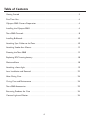
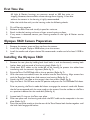
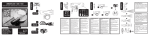
Owner’s Manual
5060
www.uwimaging.com
Welcome
Congratulations on your purchase of a Tetra 5060 digital still housing.
Please inspect the packaging of your product to verify that there was no damage during
shipping.
If you are not familiar with your camera’s features, please take time to become familiar
with the camera before you proceed in this manual. This manual assumes you have a
working knowledge of your camera and will only cover operational procedures relative
to the Tetra housing.
Periodically refer to the website for instruction revisions.
http://www.uwimaging.com
Caution - Caution - Caution - Caution - Caution
We hope you have a wonderful underwater experience with Light & Motion equipment.
To increase your enjoyment and the life span of your new gear please take an extra
minute to review these general recommendations.
•
•
•
•
•
Check the operation of all your equipment several weeks prior to your trip. If
maintenance or repair is necessary, then time is available for both shipping and repair
scheduling.
Never transport or ship the housing with the camera inside. This may damage your
camera.
Never leave your housing in the rinse tank, it may be damaged by other equipment.
When removing the camera from the housing after a dive, do so in a dry controlled
environment away from other SCUBA related equipment. This prevents water from
other equipment or water from another diver accidentally entering the housing.
If a product is flooded, immediately rinse it with fresh water. Most parts will be
salvageable if not corroded by salt water.
3
Table of Contents
Getting Started . . . . . . . . . . . . . . . . . . . . . . . . . . . . . . . . . . . . . . . . . . . . . . . . . . . . . . . . . .5
First Time Use . . . . . . . . . . . . . . . . . . . . . . . . . . . . . . . . . . . . . . . . . . . . . . . . . . . . . . . . . . .6
Olympus 5060 Camera Preparation . . . . . . . . . . . . . . . . . . . . . . . . . . . . . . . . . . . . . . . . . .6
Installing the Olympus 5060 . . . . . . . . . . . . . . . . . . . . . . . . . . . . . . . . . . . . . . . . . . . . . . . .6
Tetra 5060 Controls . . . . . . . . . . . . . . . . . . . . . . . . . . . . . . . . . . . . . . . . . . . . . . . . . . . . . . 8
Installing Bulkheads . . . . . . . . . . . . . . . . . . . . . . . . . . . . . . . . . . . . . . . . . . . . . . . . . . . . . .10
Attaching Sync Cables to the Tetra . . . . . . . . . . . . . . . . . . . . . . . . . . . . . . . . . . . . . . . . . .10
Attaching Strobe Arm Mounts . . . . . . . . . . . . . . . . . . . . . . . . . . . . . . . . . . . . . . . . . . . . .12
Shooting the Tetra 5060 . . . . . . . . . . . . . . . . . . . . . . . . . . . . . . . . . . . . . . . . . . . . . . . . . .12
Replacing ROC housing battery . . . . . . . . . . . . . . . . . . . . . . . . . . . . . . . . . . . . . . . . . . . .18
Moisture Alarm . . . . . . . . . . . . . . . . . . . . . . . . . . . . . . . . . . . . . . . . . . . . . . . . . . . . . . . . .18
Attaching a focus light . . . . . . . . . . . . . . . . . . . . . . . . . . . . . . . . . . . . . . . . . . . . . . . . . . . .19
Lens Installation and Removal . . . . . . . . . . . . . . . . . . . . . . . . . . . . . . . . . . . . . . . . . . . . . .22
After Diving Care . . . . . . . . . . . . . . . . . . . . . . . . . . . . . . . . . . . . . . . . . . . . . . . . . . . . . . .24
O-ring Care and Maintenance . . . . . . . . . . . . . . . . . . . . . . . . . . . . . . . . . . . . . . . . . . . . . .24
Tetra 5060 Accessories . . . . . . . . . . . . . . . . . . . . . . . . . . . . . . . . . . . . . . . . . . . . . . . . . . .25
Returning Products for Care . . . . . . . . . . . . . . . . . . . . . . . . . . . . . . . . . . . . . . . . . . . . . .26
Contact Light and Motion . . . . . . . . . . . . . . . . . . . . . . . . . . . . . . . . . . . . . . . . . . . . . . . . .26
4
Getting Started
Illustrated below are the locations of Tetra’s features, ports, and functions. Take time to
familiarize yourself with the housing.
Mode Dial / ON/OFF Switch
Shutter Button / Zoom Lever
Control Dial
ROC Status LED
Rotary Latches
Write Status LED
ROC Buttons
5
First Time Use
All Light & Motion housings are pressure tested to 300 feet prior to
shipping. However, there could be unseen damage from shipping. A test dive
without the camera in the housing is highly recommended.
After the initial dive with just the housing, make the following checks.
1.
2.
3.
4.
Dry off housing exterior.
Remove the Rear Plate and visually inspect for moisture.
Reach inside the housing and trace a finger around mating surfaces.
If any water is detected, contact your housing reseller or the Light & Motion service
Department.
Olympus 5060 Camera Preparation
1.
2.
3.
Remove the camera strap and lens cap from the camera.
Install fully charged Olympus 5060 battery into the camera.
Install the media card of your choice.We recommend a media card of at least 512MB in
size.
Installing the Olympus 5060
1.
2.
3.
4.
5.
6.
Remove the rear plate by holding both latch locks in and simultaneously rotating both
latches down and rearward of the housing body (Refer fig. 1).
Guide both ROC cables to the inside left of the housing to prevent the cables from
interfering with the camera’s alignment (Refer fig. 2).
Raise the Tetra On/Off/Mode dial to the up position (Refer fig. 2).
With the camera turned off, insert the camera into the Tetra housing. Align camera lens
with the Tetra lens body, then slide camera into housing (Refer fig. 3).
Attach the ROC hot shoe to the camera’s hot shoe mount (Refer fig. 4).
Align the Tetra’s On/Off lever to the Off position and press the On/Off/Mode Dial down.
Prior to pressing the Tetra’s mode dial down to engage the camera’s mode dial. Rotate
the dial to correspond with the same mode as the camera. Use the red dot on the Tetra
as a position indicator for the mode dial (Refer fig. 6)
7.
8.
9.
Inspect both O-rings on the Tetra rear plate.
Place rear plate near the housing and attach the ROC cable to the receptacle in the rear
plate (Refer fig. 5).
Press the rear plate evenly on the the rear of the Tetra. Rotate both latches together until
the latch locks engage the latches.
6
(Fig. 1)
(Fig. 2)
(Fig. 3)
(Fig. 4)
(Fig. 5)
7
(Fig. 6)
Tetra 5060 Controls
Top Housing Controls
Shutter-Release Button: Presses the camera’s shutter-release button. Press the button half
way for the camera to auto-focus, press completely down when you’re ready to take a
picture (Refer fig. 7).
Zoom Lever: Zooms the camera’s lens to telephoto or wide-angle (Refer fig. 7).
Mode Dial: Accesses the camera’s Mode Dial (Refer fig. 8).
Flower button: Accesses the camera’s AF Macro Mode (Refer fig. 9)
Rear Plate Controls
ROC button:Activates ROC and toggles between Digital TTL and Manual strobe control
(Refer fig. 10).
+ button: Increases strobe power (Refer fig. 10).
- button: Decreases strobe power (Refer fig. 10).
Control Dial:Turns camera’s control dial (Refer fig 12).
AEL: Access the camera’s Erase and AEL features (Refer fig 12).
Monitor button: Turns camera’s LCD on and off. Press once to turn screen information
off; Press twice to turn LCD off (Refer fig 12).
Menu button: Access the camera’s menu and OK button (Refer fig 12).
Card buttons: Accesses camera’s Card button (Refer fig 12).
Exp. Comp.: Used to change aperture in Manual shooting Mode by pressing and holding
and rotating the Control Dial (Refer fig 11).
Flash button: Access the camera’s flash control (Refer fig. 11).
Quick View button: Displays the last photo taken (Refer fig 12).
8
(Fig. 7)
(Fig. 8)
(Fig. 9)
(Fig. 10)
(Fig. 11)
9
(Fig. 12)
Installing Bulkheads
1.
2.
3.
4.
5.
6.
7.
Remove bulkhead cap by inserting a coin into the slot in the cap and turning counterclock wise (Refer fig. 13).
Check the O-ring and sealing surface of new bulkhead.
Insert the wires of the new bulkhead through the opening of the Tetra
(Refer fig. 14).
Seat the bulkhead onto the housing and turn clockwise to hand tighten.
Tighten the bulkhead with a 3/4” wrench.
Connect the bulkhead wire plug, now on the inside of the Tetra, to the white connector
on the ROC board (Refer fig 15).
Flatten bulkhead wires inside against the top of the Tetra to insure the wires don’t
interfere with the camera (Refer fig. 16).
Attaching Sync Cables to the Tetra
Nikonos Style
1.
2.
3.
Align the index mark on the sync cord with the guide mark on the Tetra bulkhead. Push
the sync cord into the bulkhead connector.
Turn the threaded connector until it is seated firmly into the bulkhead.
If the sync cable has a locking ring, turn the locking ring until it is hand tight and has
secured the sync cable.
Wetlink Style
1.
1.
2.
Apply silicon grease to Wetlink sync cable contacts.
Align all five pins of the Wetlink Sync cable with the five pin receptor of the bulkhead.
Push firmly until the pins are firmly seated in the bulkhead.
Wetmate sync cords and bulkheads are designed to be impervious to water.To ensure
long-term performance, flush with fresh water and dry contacts if exposed to salt water.
10
(Fig. 13)
(Fig. 14)
(Fig. 15)
(Fig. 16)
11
Attaching Strobe Arm Mounts
Identify all the parts in the strobe arm mount accessory kit. It should contain:Two base
mounts, two hex keys, two small O-rings and two green tipped set screws. For visual
identification of kit refer to fig. 19.
1)
2)
3)
4)
5)
Remove the Rear Plate.
Remove the two upper shoulder screws from the housing using the larger
supplied hex key.
Place the small supplied o-ring onto each shoulder screw (Refer fig. 20).
Place the strobe arm mount labeled “L” onto the upper left arm attachment point of the
housing.
Install one of the shoulder screws through the arm mount and tighten into housing using
hex key (Refer fig. 21).
Ensure shoulder screw is fully seated so rear plate is able to completely seal.
Occasionally check for tightness.
6)
7)
8)
9)
Insert a small green tipped set screw into the threaded hole on top of the arm mount.
Orient the screw with the green tip pointed down (Refer fig. 22).
Tighten set screw using smaller supplied hex key.
Repeat steps 3-6 for installing the right arm mount.
Attach the hand strap by threading the hand strap through slots in right strobe arm
mount.
12
(Fig. 19)
(Fig. 20)
(Fig. 21)
(Fig. 22)
F
–
-1
–
-2
–
-3
–
-4
-5
-6
-7
(Fig. 23)
13
(Fig. 24)
=
=
=
=
=
=
=
=
=
=
=
=
Ikelite 400
Ikelite 200
Ikelite DS-125
Ikelite 100
Ikelite DS-50
Ikelite 50
Nikonos SB-105 / SB-103
Nikonos SB-104
Sea & Sea YS-350/300
Sea & Sea YS-120
Sea & Sea YS-90DX/90/60/50
Sea & Sea YS-30
Shooting the Tetra 5060
ROC Defined
ROC is a revolutionary new strobe controller that is built into the Tetra 5060 housing.
ROC enables the photographer to shoot in Digital TTL and Manual
exposure modes. Both modes are accessed and strobe power levels controlled through
the LED panel located on the back of the Tetra 5060 (Refer fig 23).
Programming ROC
ROC only functions successfully by programming the type of strobe(s) being used.
Program ROC prior to diving. Once ROC is programmed it will never have to be reprogrammed unless a different model strobe is attached. ROC will retain its programming
even when the ROC battery is changed or removed.
ROC’s default strobe profile is for Sea & Sea YS-90DX/90Duo/90 Auto/60/50. If you are
using different strobe(s) use the following procedure to change the ROC strobe profile.
If you use different type or brands of strobes with the Tetra 5060, only one type may be
programmed. When shooting in manual mode the un-programmed strobe’s light output
may not correspond exactly with the f/stop scale of the ROC LED panel.
1.
2.
3.
4.
“Wake-up” ROC by pressing the ROC button (Fig. 23).
Press and hold the ROC Power button until the power level LED begins to blink.
Press the +/- buttons to position the power level LED in the appropriate location. Refer
(Fig. 24) to determine which location is for which type of strobe.
When the power level LED is positioned in the appropriate location, press the ROC
button to activate the strobe profile. ROC will save this profile and then return you to
whatever power level the strobe was in previously.
During the programming process, if programming is idle for 60 seconds ROC will record
the strobe profile of the current LED position and enter stand-by mode.
ROC Stand-by and Time Out schedule
ROC is fully active when it shows the strobe power level or the Status LED is illuminated
green (green indicates TTL mode).
After 60 seconds of inactivity ROC enters stand-by mode. ROC is still active but turns
off the LEDs to conserve battery power. ROC will return to the active mode by pressing
any ROC button or the shutter release.
14
If ROC is in stand-by mode and the shutter button is pressed, ROC will process the
shutter command and return to the active status.
ROC will turn off after 30 minutes of inactivity.You must press the ROC button to turn
ROC on again.
Using ROC for manual strobe control
1.
2.
3.
Turn strobe(s) on and in the TTL position.Turn the camera’s flash off.
Press the ROC button to turn on ROC and press again to switch ROC to Manual mode
from TTL.When in Manual mode, status LED is off.
Press the + button to increase the strobe’s power or the - button to decrease the
strobe’s power.
Shooting the Tetra 5060 with ROC in TTL
Not all strobes are capable of the double-flash performance required by the Tetra 5060’s
TTL
system. The
following
list
show
the
strobes
that
ARE
compatible.
Ikelite DS-125
Ikelite DS-50
Sea & Sea YS-350/300
Sea & Sea YS-120
Sea & Sea YS-90DX/90/60/50
Sea & Sea YS-30
If your strobe is not compatible, you will not be able to toggle between TTL and Manual
modes. ROC will always be in manual mode.
1.
2.
Turn strobe(s) on and in the TTL position.Turn on the camera’s flash.
Press the ROC button to turn on ROC.TTL is indicated by a green status LED.
After a photo is taken the power level will indicate the output power level the strobe
produced.
If the status LED flashes red and green alternately, this is a signal the strobe didn’t
produce enough light to properly expose the photo.
If TTL is not providing the desired exposure you can switch to manual with a push of a
button. If you want more light press the “+” button. For less light press the “-” button.
15
Shooting Techniques
Digital cameras have many features and controls that initially seem overwhelming. The
controls listed below are the most commonly accessed with the Tetra. It is
recommended to familiarize yourself with these controls first and understand how they
assist you with digital underwater photography.
Zoom Lever (Refer fig 25):
Use the lever to optically increase or decrease the distance from your subject. For most
subjects zoom wide when shooting wide-angle and zoom in when shooting macro.
Flower Button (Refer fig. 26):
Press this button to activate the Auto Focus and Macro Mode of the camera.When you
are close to subjects, activate the Macro mode to allow the camera to focus closer.
Quick View Button (Refer fig. 27):
To view your photo after you take it, press the Quick View button. This allows you to
study the photo for exposure and composition.
Control Dial (Refer fig. 28):
In Manual mode, use the Control Dial to change shutter-speeds. Use the Control dial in
conjunction with the Exp. Comp. button to change f-stops.
ROC (Refer fig. 29):
ROC delivers dynamic strobe control to make subtle or dramatic lighting changes
without making changes to the f/stop, shutter speed, strobe position, subject distance or
composition. Simply press the “+” button for more light or the “-”
button for less light.
Shutter Release (Refer fig 25):
To take a photo, press the shutter button. Press and hold the shutter release
Exposure Compensation Button (Refer fig. 30):
When shooting in Manual Mode, press and hold the Exposure Compensation button
while turning the Jog Dial to change f/stops.
16
(Fig. 25)
(Fig. 26)
(Fig. 27)
(Fig. 28)
(Fig. 29)
17
(Fig. 30)
Replacing ROC Housing battery
ROC will indicate a low battery status by flashing a slow red Status LED.
1.
2.
Replacement battery type is CR2450 and can be found at most camera stores.
When installing the battery follow the + and - battery orientation on the circuit board.
ROC will retain the most recent strobe profile programmed even when the battery has
been removed (Refer fig 31).
Moisture Alarm
The Tetra 5060’s moisture alarm gives a visual indication that water has been detected
inside of the housing (Refer fig 32).
The two metal contacts at the bottom right of the ROC board in the Tetra Rear Plate
are the sensing contacts that react to water (Fig. 32). If water touches these contacts the
ROC LED panel will display an array of lights.
The moisture alarm will continue its display of lights until it no longer detects water and
continue the display for 5 additional minutes.To terminate the alarm , clear the contacts
of moisture and press the “+” button for three seconds.
(Fig. 31)
(Fig. 32)
18
Attaching a focus light
Why use a focus light?
Night diving , wreck diving, cave exploration or heavy kelp canopies are diving scenarios
where ambient light is not available to help cameras auto focus.
The Olympus 5060 auto focus system depends on identifying subject contrast. Without
a strong light source illuminating your subject, the camera may fail to focus properly or
not focus at all.
There are two type of focus lights available for the Tetra 5060.
Classic Focus Light
The Classic Focus Light is a halogen
light system powered by a light weight
rechargeable NiMH battery.
The broad beam of the Classic Focus
Light not only lights up your subject,
but doubles as a dive light and will help
you identify subjects missed by
narrower lights.
Tetra Pointer Light
The pointer lights is a simple solution
for adding just enough light. The
pointer light provides a narrow beam
to assist your camera.The pointer light
is powered by 4 AA batteries.
19
Installing Classic Light (Optional)
Attach the battery pod to the bracket.
1) Slide the raised pod detail through the T shaped channel of the bracket.
2) Tighten the two set screws using the supplied allen key.
Mounting the bracket to the Tetra.
1) Remove the black nylon tips from the bracket using a phillips head screw driver.
2) Loosely center the bracket on the bottom of the Tetra.
3) Orient the long slot of the bracket over the tripod mount of the Tetra.
4) Place the split washer onto the screw.
5) Place the flat washer onto the screw.
6) Place screw and washers onto the bottom of the bracket so the screw passes through
the bracket and aligns with the tripod mount of the Tetra.
7) Tighten the screw with the supplied allen key.
Mounting the base piece to the Tetra.
1) Place the base piece over the mounting details of the housing.
2) Insert the flat head screw through the base piece and tighten using the supplied allen key.
Attach the light arm to arm base by pressing FIRMLY until arm snaps into place.
Align top of arm with light head base and press FIRMLY together.Arm will snap into position.
To remove light head from arm,“break” the arm at the upper most joint. Apply pressure on the
light arm and not the light head. Do not apply pressure to the light head base. Doing so may
cause the base to break from the light head damaging the system.
Installing the Tetra Pointer Light (Optional)
1.
2.
3.
4.
5.
Identify the appropriate parts in the Tetra Pointer Light Kit.
Kit includes the following (Refer fig. 37).
Hex screw, 1/4” base piece, Infinity arm, modeling light and light bracket.
Position the base piece details on the detail of the Tetra’s accessory hole.
Place the hex screw through the base piece and tighten with hex key.
Place Infinity arm with holder over the base piece and press firmly down until the Infinity
arm snaps into position (Refer fig. 38).
20
(Fig. 33)
(Fig. 34)
(Fig. 35)
(Fig. 36)
(Fig. 37)
21
(Fig. 38)
Lens Installation and Removal
To remove the flat port
1.
2.
3.
Slide locking pin away from lens (Refer fig. 39)
Rotate optic counter clockwise.
Pull away from housing.
To install the flat port
1.
2.
3.
4.
Perform an o-ring inspection.
Align lens to housing details.
Press lens into housing.
Rotate clockwise until locking pin engages.
Installing the wide angle lens
1.
2.
3.
4.
Perform an o-ring inspection.
Align the red dot beside the arrow indicator with the machined circle on the Tetra and
press the lens into the housing. The lens should be seated evenly around the sealing
surface.
Rotate the lens in the direction of the arrow, clock-wise.
Rotate the lens until the locking pin engages the detail and locks the lens onto the
housing. The red dot next to the words Light & Motion should now be aligned to the
machined detail on the Tetra housing.
Installing the wetmate macro lens
1.
2.
3.
Orient the housing so the it is facing upwards or towards the surface of the water.
Place the macro lens onto the top of the flat port.
Gently rotate the macro lens clockwise. When the threads align, the macro lens will
thread into the flat port properly.
22
(Fig. 39)
(Fig. 40)
(Fig. 41)
23
After Diving Care
1.
2.
3.
Immediately submerge the housing in fresh water. While in fresh water, work the Mode
Dial, Zoom Lever and all the buttons, to work any remaining salt water out of the
housing.
Remove housing from rinse tank and then simply towel dry.
Do not leave the Tetra in a rinse tank. Other housing or equipment may be dropped into
the rinse tank on top of the Tetra causing damage or comproimising the seals.
O-ring Care and Maintenance
O-rings are the critical component that keeps water out of the housing. Routinely
inspect o-rings and replace at least once a year. If your o-rings are damaged, contact
the Light & Motion service department for an o-ring replacement kit.
Follow these steps for proper o-ring function.
1) The sealing system used on the rear plate incorporates two o-rings. This is the most
critical area of the housing for maintenance and should be inspected before every dive.
2) Make sure the rear plate o-rings and the mating surface on the inside of the main housing
are clean from grit, hair, lint and anything that could potentially breach the o-ring seal.
3) After frequent diving or if o-rings appear dirty, remove o-rings and clean the grooves.To
remove o-rings, use finger pressure or the rounded edge of a plastic card to lift the oring out of the groove.
4)
5)
6)
7)
8)
Never use a metal object to remove an o-ring. It will cause damage
to the o-ring and mating surface.
To check o-rings for damage, place the o-ring between the index finger and thumb.Then
pull the o-ring through your fingers, feeling for any debris or wear.
If o-rings are dirty, it is best to replace them.Washing dirty o-rings with soap and water
is not recommended. Soap breaks down the lubricants and will compromise the integrity
of the seal.
Properly greased o-rings will help maintain sealing integrity and minimize o-ring
degradation. Use enough grease to lubricate the o-ring thoroughly, but not so much that
it will attract additional debris.
Clean the groove with a lint free swab or the folded edge of a paper towel.
All of the lenses for the housing also utilize two o-ring seals.Also check these seals every
time the lens is removed.
Tetra 5060 O-ring Replacement Kit part # 854-0178 includes:
Two o-rings for the Rear Plate, two o-rings for lens, and o-ring grease.
24
Tetra 5060 Accessories
Tetra 5060 Fault Free Warranty . . . . . . . . . . . . . . . . . .905-0200
Tetra 5060 Wide-Angle Lens . . . . . . . . . . . . . . . . . . . . .854-0174
Tetra 5060 Wetmate Macro Lens . . . . . . . . . . . . . . . . .854-0175
Tetra 5060 Nikonos Bulkhead . . . . . . . . . . . . . . . . . . . .854-0110
Tetra Wetlink Bulkhead . . . . . . . . . . . . . . . . . . . . . . . . .854-0112
Tetra Wetlink Sync Cord . . . . . . . . . . . . . . . . . . . . . . . .854-0044
Tetra Custom Travel Case . . . . . . . . . . . . . . . . . . . . . . .775-0024
Classic Focus Light . . . . . . . . . . . . . . . . . . . . . . . . . . . . .850-0055
Tetra Pointer Light . . . . . . . . . . . . . . . . . . . . . . . . . . . . .854-0051
Tetra 5060 O-ring Kit . . . . . . . . . . . . . . . . . . . . . . . . . .854-0178
Light & Motion coil Lanyard . . . . . . . . . . . . . . . . . . . . .802-0167
25
Returning Products for Care
1)
2)
We highly recommend a factory annual service to maintain proper
operation of your Tetra Housing
Before returning your Light & Motion product for care, please call or email our service
department for a RMA number.
Ship your product pre-paid freight with the return number printed on the outside of the
box. It is recommended that you keep your shipper’s tracking number until the product
is returned to you.
Warning: Do not ship your camera inside the housing. Shipping
companies may drop your system from up to three feet which could
damage your camera.
Contact Light and Motion
Sales Department:
831-645-1525 • Fax 831-375-2517
European Service Center
FEP Ltd.
Attn: Steve Mawle
Aston House
Heimdon Rd.
Sulgrave
OX17-2SQ
England
01295 768686 (ph.)
01295 768446 (fax)
[email protected]
www.fep.co.uk
Service Department:
831-645-1572 • Fax 831-375-2517
Mail:
Light & Motion
300 Cannery Row
Monterey, CA 93940
E-mail:
[email protected]
World Wide Web:
www.uwimaging.com
26
300 Cannery Row • Monterey, CA 93940
(831) 645-1525 • Fax (831) 375-2517
www.uwimaging.com
905-0243-A