1
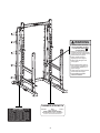
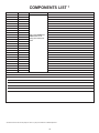
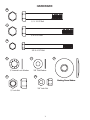
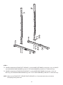
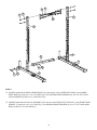
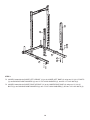
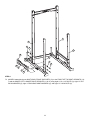
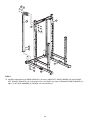
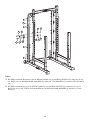
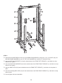
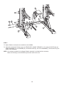
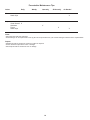
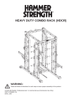
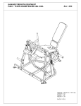
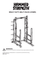
HEAVY DUTY MULTI RACK (HDMR) WARNING: Read and follow all directions for each step to insure proper assembly of this product. CLASS SB (Studio): Professional and / or commercial use (Commercial Use Only) PART #7671101 B-1 DATE: 2/08 HAMMER STRENGTH HEAVY DUTY RACKS SAFETY & WARRANTY Purchasers of Hammer Strength products should read the Owner's Manual and all of the warning labels on the products before using them. Because these products may be used in commercial settings, it is the purchaser's responsibility to instruct all individuals, whether users, trainers or observers, on the proper usage of the equipment. Contact Hammer Strength if you do not know how to use this equipment. Hammer Strength recommends that all commercial fitness equipment be used in a supervised area. Hammer Strength also recommends that the equipment be located in an access controlled area. The extent of control is at the discretion of the owner. SECURING EQUIPMENT: All strength equipment must be secured to the floor to a solid, level surface to stabilize and eliminate rocking or tipping over. This must be performed by a licensed contractor. Hammer Strength recommends that all users be informed of the following prior to using Hammer Strength equipment: PROPER USAGE 1. It is imperative that Hammer Strength equipment be used properly to avoid injury. Do not use any equipment for purposes other than those specified by the manufacturer. 2. Keep body parts (hands, feet, hair, etc.) and clothing away from moving parts to avoid injury. 3. Injuries may result if you exercise improperly or excessively. It is recommended that all individuals consult a physician prior to commencing an exercise program. If at any time during exercise you feel faint, dizzy or experience pain, stop and consult your physician. 4. When adjusting any seat or range of motion limiter, make certain that the adjusting pin is fully engaged in the hole to avoid injury. CHECK FOR DAMAGED PARTS 1. DO NOT use or permit the use of any equipment that is damaged or has worn or broken parts. For all Hammer Strength equipment, use only replacement parts supplied by Hammer Strength. 2. MAINTAIN LABELS AND NAMEPLATES: Do not remove labels for any reason. Labels contain important information. If unreadable or missing, contact Hammer Strength for a replacement. 3. MAINTAIN ALL EQUIPMENT: Preventative maintenance is the key to smooth operating equipment. Equipment should be inspected at regular intervals. See the Maintenance section of this manual for recommended maintenance intervals. 4. Ensure that any person(s) making adjustments or performing maintenance or repair of any kind is qualified to do so. Hammer Strength will provide service and maintenance training at one of its facilities upon request or in the field if proper arrangements are made. SPECIFIC OPERATING WARNINGS 1. UNDERSTANDING THE FULL EXTENT OF EACH AND EVERY WARNING IS IMPORTANT. IF ANY WARNING IS UNCLEAR, ASK HAMMER STRENGTH PERSONNEL FOR CLARIFICATION. 2. Keep children away from strength equipment. 3. Use only olympic style weight plates (2.0" Bore) for training weight. Only add weight up to the load limits of the unit and that can be fully placed on the weight horn. Contact a Hammer Strength representative with any questions regarding proper weights and loading. 2 WARNING SERIOUS INJURY CAN OCCUR ON THIS EQUIPMENT. YOU MUST FOLLOW THESE PRECAUTIONS TO AVOID INJURY! 1. Before using, read all the warnings and obtain instruction on the use of this machine. Use only for intended exercise. DO NOT modify the equipment. 2. Obtain a medical exam before beginning any exercise program. 3. Keep body and clothing free of all moving objects. 4. Inspect equipment daily. Tighten all loose connections, and replace worn parts immediately. DO NOT use if it appears damaged. 5. Children must not be allowed near this machine. Supervise teenagers. 6. DO NOT REMOVE THIS LABEL. REPLACE IF DAMAGED. HAMMER/STRENGTH This exercise machine is covered by one or more of the following U.S. patents: 5,044,631; D321,027; 5,135,449; D321,026; 5,066,003; D321,391; 5,006,004; D321,389; 5,100,080; D321,390; 5,135,456; 5,171,198; 5,180,354; D321,387; 5,273,505; 5,273,504; 5,125,881; 5,181,896; 5,050,873; 6,203,474B1 and other patents pending. MACHINE # MODEL MFG. & DESIGN BY SERIAL # GARY JONES & THE TROOPS MACHINE WARRANTY VOID IF TAG REMOVED For Service Call Life Fitness 800-351-3737 3 LIMITED WARRANTY WHAT IS COVERED This Hammer Strength commercial exercise equipment (Signature Benches and Racks) is warranted to be free of all defects in material and workmanship to the original purchaser for the specific items and duration listed: O 10 years on structural frame O 1 year on grips O 1 year for rust or corrosion of structural frame. Scratches or scrapes where the subsurface of the unit has been exposed must have been properly repaired by the customer. O 90 days on upholstery and any items not specified (including labor). Hammer Strength will ship to you at our expense, any repair parts covered by the warranty as stated. If the Product is deemed not repairable by Hammer Strength authorized personnel, we reserve the right to replace any part or the entire Product at our option within the stated warranty period. WHAT IS NOT COVERED Any failures or damage caused by unauthorized service, misuse, accident, negligence, improper assembly or installation, debris resulting from construction activities in the vicinity of the Product, any alterations or modifications made to the Product without written authorization by Hammer Strength, or by failure on your part to use, operate, and maintain the Product as set out in your Operation Manual. All terms of this warranty are void if this product is moved beyond the continental borders of North America (excluding Hawaii) and are then subject to the terms provided by that country's authorized Hammer Strength Representative. TRANSPORTATION & INSURANCE FOR SERVICE If the Product or any covered part must be returned to a service facility for repairs, Hammer Strength will pay all transportation and insurance charges for the first year. You are responsible for transportation and insurance charges for year 2 and beyond. HOW TO GET PARTS & SERVICE Simply call Customer Support Services at (800) 351-3737 or (847) 451-0036, Monday through Friday from 8:00 a.m. to 6:00 p.m. Central Standard Time, and tell them your name, address and the serial number of your Product. They will tell you how to get a replacement part, or, if necessary, arrange for service where your Product is located or advise you on how and where to ship the Product for service. Before shipping: 1. Obtain a Return Authorization Number (RA#) from Customer Support Services 2. Securely pack your Product (use the original shipping carton, if possible) 3. Write the RA# on the outside of the carton 4. Insure the Product, and 5. Include a letter explaining the defect or problem and a copy of your proof of purchase if you believe the service is covered by warranty Life Fitness World Headquarters Attn: CSS Help Desk 5100 N. River Rd. Schiller Park, IL. 60176 4 LIMITED WARRANTY EXCLUSIVE WARRANTY THIS LIMITED WARRANTY IS IN LIEU OF ALL OTHER WARRANTIES OF ANY KIND EITHER EXPRESSED OR IMPLIED, INCLUDING BUT NOT LIMITED TO THE IMPLIED WARRANTIES OF MERCHANTABILITY AND FITNESS FOR A PARTICULAR PURPOSE, AND ALL OTHER OBLIGATIONS OR LIABILITIES ON OUR PART. We neither assume nor authorize any person to assume for us any other obligation or liability concerning the sale of this Product. Under no circumstances shall we be liable under this warranty, or otherwise, for any damage to any person or property, including any lost profits or lost savings, for any special, indirect, secondary, incidental or consequential damages of any nature arising out of the use of or inability to use this Product. Some states do not allow the exclusion or limitation of implied warranties or of liability for incidental or consequential damages, so the above limitations or exclusions may not apply to you. CHANGES IN WARRANTY NOT AUTHORIZED No one is authorized to change, modify or extend the terms of this limited warranty. EFFECT OF STATE LAWS This warranty gives you specific legal rights and you may have other rights, which vary, from state to state. OUR PLEDGE TO YOU Our Products are designed and manufactured to the highest standards. We want you completely satisfied with our Products and will do everything possible under the terms of this warranty to keep you secure in knowing you have bought the best! 1. Frame Construction: Frame is constructed of mechanical quality steel purchased in mill run quantities. Frame is primarily 3" x 3" square shaped tubing and 3” x 2” shaped tubing with 7 gauge and 11 gauge wall thickness. 2. Frame Finish: The frames are coated with an electrostatic epoxy powder coat finish. 3. Bolts: Most hardware is English and has a corrosion resistant finish. Grade 5 or greater in strength. 4. Equipment Anchoring: All machines have holes in the feet, these allow easy anchoring to the floor. Life Fitness recommends that all machines be anchored to the floor to minimize the possibility of tipping. 5. Liability Insurance: Certificate of insurance available upon request. HEAVY DUTY MULTI RACK Product #-HDMR8 Machine Weight: 620 lbs. (281 kgs.) Size: 76.5” L (193 cm) x 66” W (168 cm) x 97” H (246 cm) Live Area: 76.5” L (193 cm) x 120” W (305 cm) x 105” H (267 cm) Max Training Weight: 855 lbs. (388 kgs.) HEAVY DUTY MULTI RACK Product #-HDMR9 Machine Weight: 632 lbs. (286 kgs.) Size: 76.5” L (193 cm) x 66” W (168 cm) x 109” H (277 cm) Live Area: 76.5” L (193 cm) x 120” W (305 cm) x 117” H (297 cm) Max Training Weight: 855 lbs. (388 kgs.) 5 COMPONENTS LIST * ITEM NO. 1 QTY. 1 PART NO. HDMR8-CFUPL-0 DESCRIPTION FRONT LEFT UPRIGHT 2 1 HDMR8-LSFL-0 3 42 HHB.5X4.5 4 54 H-BACK-WASH 5 44 WASH.5STAR 6 44 NUT.5LOCK 7 1 HDMR8-CFUPR-0 8 1 HDMR8-LSFR-0 LOWER RIGHT BASE 9 1 HDMR8-RX-0 REAR CROSS BRACE 10 1 11 1 12 1 Refer HDMR8-CPU-0 to the HDMR8 and HDMR9 Parts List to HDMR8-CSUPL-0 identify part numbers for HDMR8-CSUPR-0 orders. 13 2 LOWER LEFT BASE 1/2 X 4-1/2” BOLT BACKING DOME WASHER 1/2" INTERNAL LOCK WASHER 1/2" THICK LOCK NUT FRONT RIGHT UPRIGHT PULL-UP SUPPORT SHORT LEFT UPRIGHT SHORT RIGHT UPRIGHT HDMR8-FX-0 MULTI RACK FRONT SUPPORT 14 2 HDMR8-RUP-0 15 10 ANG-WT-HORN-ASSY REAR UPRIGHT 16 10 HHB.375X4.5 17 20 WASH.375SAE 3/8" SAE FLAT WASHER 18 10 NUT.375LOCK 3/8" THICK LOCK NUT 19 1 HD-SDL-00 SHORT BENCH LOCK 20 2 HHB.5X3.5 21 1 HDMR8-CBSL-0 LEFT BAR SUPPORT 22 1 HDMR8-CBSR-0 RIGHT BAR SUPPORT 23 2 HDMR8-CBC-0 24 1 WARNING LARGE-V 25 1 SERIAL NUMBER 26 1 PATENT WEIGHT HORN 3/8 X 4-1/2” BOLT 1/2 X 3-1/2” BOLT BAR CATCH LARGE VERTICAL WARNING SERIAL NUMBER PATENT DECAL REQUIRED TOOLS * 3/4” WRENCH * 9/16” WRENCH * RATCHET with 9/16” SOCKET * RATCHET with 3/4” SOCKET * 7/32” ALLEN WRENCH * Contact Customer Service at (800) 351-3737 or (847) 451-0036 for a detailed parts list. 6 HARDWARE: 20 ½ X 3-1/2” Bolt 3 ½ X 4-1/2” Bolt 16 3/8 X 4-1/2” Bolt 5 17 ½” Internal Lock Washer 6 4 3/8” Flat Washer 18 Backing Dome Washer 3/8” Lock Nut ½” Lock Nut 7 7 1 6 5 4 3 8 2 STEP 1: LOOSELY assemble the FRONT LEFT UPRIGHT (1) to the LOWER LEFT BASE (2) using two 1/2 X 4-1/2” BOLTS (3), two BACKING DOME WASHERS (4), two 1/2” INT LOCK WASHERS (5) and two 1/2” LOCK NUTS (6). LOOSELY assemble the FRONT RIGHT UPRIGHT (7) to the LOWER RIGHT BASE (8) using two 1/2 X 4-1/2” BOLTS (3), two BACKING DOME WASHERS (4), two 1/2” INT LOCK WASHERS (5) and two 1/2” LOCK NUTS (6). NOTE: Make sure the FRONT LEFT & FRONT RIGHT UPRIGHTS (1 & 7) face the inside of the unit with the slot openings facing each other. 8 5 3 6 4 10 7 1 9 8 5 3 4 6 2 STEP 2: LOOSELY assemble the REAR CROSS BRACE (9) to the bottom of the LOWER LEFT BASE (2) and LOWER RIGHT BASE (8) using four 1/2 X 4-1/2” BOLTS (3), four BACKING DOME WASHERS (4), four 1/2” INT TOOTH LOCK WASHERS (5) and four 1/2” LOCK NUTS (6). LOOSELY assemble the PULL-UP SUPPORT (10) to the top of the FRONT LEFT UPRIGHT (1) and FRONT RIGHT UPRIGHT (7) using four 1/2 X 4 1/2” BOLTS (3), four BACKING DOME WASHERS (4), four 1/2” INT LOCK WASHERS (5) and four 1/2” LOCK NUTS (6). 9 12 11 6 5 8 4 3 2 STEP 3: LOOSELY assemble the SHORT LEFT UPRIGHT (11) to the LOWER LEFT BASE (2) using two 1/2 X 4-1/2” BOLTS (3), two BACKING DOME WASHERS (4), two 1/2” INT LOCK WASHERS (5), and two 1/2” LOCK NUTS (6). LOOSELY assemble the SHORT RIGHT UPRIGHT (12) to the LOWER RIGHT BASE (8) using two 1/2 X 4-1/2” BOLTS (3), two BACKING DOME WASHERS (4), two 1/2” INT LOCK WASHERS (5), and two 1/2” LOCK NUTS (6). 10 7 1 3 4 12 13 11 4 3 5 6 6 5 STEP 4: LOOSELY assemble the two MULTI RACK FRONT SUPPORTS (13) to the FRONT LEFT & RIGHT UPRIGHTS (1 & 7) and the SHORT LEFT & SHORT RIGHT UPRIGHTS (11 & 12) using eight 1/2 X 4-1/2” BOLTS (3), eight 1/2” INT LOCK WASHERS (5), eight 1/2” BACKING DOME WASHERS (4), and eight 1/2” LOCK NUTS (6). 11 6 5 7 14 1 4 3 6 5 8 4 3 2 STEP 4: LOOSELY assemble the two REAR UPRIGHTS (14) to the LOWER LEFT & RIGHT BASES (2 & 8) and FRONT LEFT & RIGHT UPRIGHTS (1 & 7) using eight 1/2 x 4-1/2” BOLTS (3), eight 1/2” BACKING DOME WASHERS (4), eight 1/2” INT LOCK WASHERS (5), and eight 1/2” LOCK NUTS (6). 12 14 4 3 5 4 17 16 17 6 18 15 STEP 5: SECURELY assemble the bottom of the ten WEIGHT HORNS (15) to the REAR UPRIGHTS (14) using ten 3/8 x 41/2” BOLTS (16), ten BACKING DOME WASHERS (4), twenty 3/8” FLAT WASHERS (17), and ten 3/8” LOCK NUTS (18). SECURELY assemble the top of the WEIGHT HORNS (15) to the REAR UPRIGHTS (14) using ten 1/2 X 4-1/2” BOLTS (3), ten 1/2” INT TOOTH LOCK WASHERS (9), ten BACKING DOME WASHERS (4), and ten 1/2” LOCK NUTS (5). 13 7 1 21 22 23 20 4 9 5 6 19 STEP 6: Assemble the SHORT BENCH LOCK (19) to the REAR CROSS BRACE (9) using two 1/2 X 3-1/2” BOLTS (20), two BACKING DOME WASHERS (4), two 1/2” INT LOCK WASHERS (5), and two 1/2” LOCK NUTS (6). Insert the LEFT BAR SUPPORT (21) into the desired slots of the FRONT LEFT UPRIGHT (1), and allow it to drop down to lock in place. Insert the RIGHT BAR SUPPORT (22) into the desired slots of the FRONT RIGHT UPRIGHT (7), and allow it to drop down to lock in place. Insert one BAR CATCH (23) into the desired slots of the FRONT LEFT UPRIGHT (1), and allow it to drop down in place. Insert the remaining BAR CATCH (23) into the desired slots of the FRONT RIGHT UPRIGHT (7), and allow it to drop down in place. Securely tighten all loose assemblies. 14 A A B C G D E F 7 1 STEP 7: Spotter Platform accessories are available for the HDMR8. Assemble each Spotter Platform (A) to the FRONT LEFT & RIGHT UPRIGHTS (1 & 7) using two BOLTS (B), two DOME WASHERS (C), two SPACERS (D), one WEAR PLATE (E), two FLAT WASHERS (F), and two NUTS (G) as shown in the illustration. NOTE: All necessary hardware for the Spotter Platform assembly is included with the accessory. Make sure the flange on the SPACER (D) faces the inside of the rack. 15 Preventative Maintenance Tips Action Daily Weekly Quarterly Bi-Annually As Needed Clean Hand Grips X Inspect Visual Overall Hardware Frame Hand Grips X X X X Clean: • Hand grips with mild soap and water. • Frame damage can be repaired with touch-up paint can be purchased from your Hammer Strength customer service representative. Inspect: • Hardware should be checked for looseness. Tighten as required. • Frames should be inspected for wear or damage. • Hand Grips should be checked for wear or damage. 16