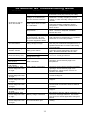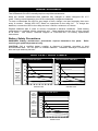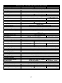
1
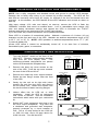
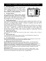
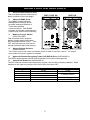
POWER PROTECTION
R
UPStation® GX
1000 VA to 3000 VA
IMPORTANT SAFETY INSTRUCTIONS
WARNING: Do not attempt to service this product or replace the
batteries yourself. Opening or removing the cover may expose you to
dangerous voltages, even if the UPS is unplugged. There are no userserviceable parts inside the unit. Refer all servicing to qualified
service personnel.
1.
2.
SAVE THESE INSTRUCTIONS. ADHERE TO ALL OPERATING INSTRUC- TIONS
AND WARNINGS ON THE UNIT AND IN THIS MANUAL.
CONSERVER CES INSTRUCTIONS. CETTE NOTICE CONTIENT DES
INSTRUCTIONS IMPORTANTES CONCERNANT LA SÉCURITÉ.
3.
Liebert Corporation neither recommends nor knowingly sells this product for
use with life support or other U.S. FDA designated ”critical” devices.
4.
CAUTION: A BATTERY PRESENTS A RISK OF ELECTRICAL SHOCK OR BURN
FROM HIGH SHORT CIRCUIT CURRENT. OBSERVE PROPER PRECAUTIONS.
5.
ATTENTION: UNE BATTERIE PEUT PRÉSENTER UN RISQUE DE CHOC
ÉLECTRIQUE DE BRULURE PAR TRANSFERT D’ÉNERGIE. SUIVRE LES
PRÉCATIONS QUI S’IMPOSENT.
6.
WHEN REPLACING BATTERIES, USE THE SAME NUMBER AND TYPE OF
BATTERIES. PROPER BATTERY DISPOSAL REQUIRED. REFER TO LOCAL
CODES.
7.
POUR LE REMPLACEMENT, UTILISER LE MEME NOMBRE ET MODELE DE
BATTERIES. L’ELIMINATION DES BATTERIES EST REGLEMENTEE.
CONSULTER LES CODES LOCAUX.
8.
WARNING: TO REDUCE RISK OF FIRE OR ELECTRIC SHOCK, INSTALL IN A
TEMPERATURE AND HUMIDITY CONTROLLED AREA FREE FROM CONDUCTIVE
CONTAMINANTS.
9.
AVERTISSEMENT: POUR REDUIRE LE RISQUE D’INCENDLE OU DE CHOC
ELECTRIQUE, INSTALLE DANS UN SECTEUR AVEC TEMPERATURE CONTROLE
ET HUMIDITE CONTROLEE EXAMPT DE POLLUANTS CONDUCTEURS.
10. Read all safety and operating instructions before operating UPS. Operate indoors
only. Protect UPS from moisture and install it in a clean environment, free from
flammable liquids, gases, or corrosive substances.
11. WARNING: Do not modify cable. Consult dealer if connector does not match
equipment. UPS must be grounded at all times while in use. Turn UPS OFF before
unplugging, or the safety ground from UPS to equipment will be removed.
12. CAUTION: Output receptacles on the UPS are electrically live if the UPS is ON, even
if the UPS is not plugged in. The on/off switch on the UPS does not electrically isolate
the internal parts. To isolate the UPS, turn it OFF and unplug it.
13. CAUTION: Ground leakage current must not exceed 2.75 milli-amperes. Most data
processing equipment meets this requirement if you use no more than 4 pieces of
equipment. Note: These instructions may be modified by local wiring regulations.
14. Unplug the UPS and turn the power switch OFF before cleaning. Use only water
dampened cloth, never liquid or aerosol cleaners.
2
15. Do not plug appliances, such as hair dryers or heaters into UPS receptacles.
16. Operate UPS only from a grounded outlet (2 wire plus ground) 120 VAC, 60/50 Hz.
17. The UPS is equipped with a grounded NEMA 5-15 input power plug. Do not defeat
the safety purpose of this plug. If unable to fully insert the plug into the outlet, contact
an electrician. All utility receptacles must be grounded as well.
18. Route power supply cords so they are not walked on or pinched.
19. Never block or insert any object into ventilation holes or other openings. Maintain a
minimum clearance of 4” all around UPS for proper air flow and cooling.
20. CAUTION: Do not open or mutilate battery.
and eyes and may be toxic.
Released electrolyte is harmful to skin
21. CAUTION: This UPS complies with the limits for a Class A digital device, pursuant to
Subpart J of Part 15 of FCC rules. These limits provide reasonable protection against
harmful interference in a commercial environment. This UPS generates, uses, and
radiates radio frequency energy and, if not installed and used in accordance with the
instruction manual, may cause harmful interference to radio communications.
Operation of this UPS in a residential area is likely to cause harmful interference which
the user must correct at his own expense.
INTRODUCTION & SYSTEM DESCRIPTION
Congratulations on choosing the Liebert UPStation® GX UPS. It provides continuous,
conditioned power to microcomputers and other data processing equipment.
Upon generation, AC power is clean and stable. However, during transmission, it may be
subject to load variations or accidents that cause power problems like low voltage, voltage
spikes, or complete power failure. These problems may interrupt computer operations,
cause data loss, or even damage equipment.
The UPS protects against many of these disturbances. It smoothes out voltage variations
and during complete power failure, supports equipment long enough for an orderly
shutdown. These compact units are available in three ratings: 1000, 1500, and 2100 VA.
This manual includes specifications for each model.
The UPStation® GX is a compact ”on-line” UPS that supplies critical equipment with
continuous premium, computer-grade power. An ”On-line” UPS continuously generates
and regulates output power, whether utility power is present or not. In contrast, a ”standby”
UPS only generates output power when utility power fails.
The UPStation® GX supplies critical equipment with clean, sinewave power to simulate
utility-generated power. Equipment like computers, monitors, printers, phone systems, and
laboratory instruments operate best on sinewave power.
The LED bar displays indicate ”percentage load” and ”battery capaci
two levels of alarms during battery operation, self-diagnostics, and a combination battery
test / alarm silence switch.
To allow communications between the UPS and a LAN server or other computer system,
the UPStation’ GX UPS is equipped with an RS-232 interface port. This port provides
detailed operating information including voltages, currents, temperature, and alarm status
to the host system when used with Liebert SiteNet soft- ware. In addition, this port allows
remote programming of UPS operation and numerous internal operating parameters.
3
MAJOR INTERNAL UPS COMPONENTS
Surge Suppression and EMI/RFI Filters
These components provide surge protection and filter electromagnetic and radio frequency
interference present in the utility line. These components enable the UPS to supply pure
sinewave power to sensitive equipment.
Power Factor Correction Circuit
This circuit changes the utility AC input to DC for use by the inverter and ensures sinewave
input current to the UPS. Sinewave input achieves two things: increased power efficiency
and reduced power distortion.
Inverter
The inverter converts the DC output of the power factor correction circuit to regulated AC
sinewave power. During either normal utility power operation or battery operation, the
inverter continuously generates and regulates output power.
Charger
The charger regulates energy from the power factor correction circuit to continuously
charge the batteries. The charger operates whenever the UPS is ON. For maximum
battery charge life and power protection, leave the UPS ON.
Battery
The sealed, maintenance-free, spill-proof batteries in the UPStation® GX last for 5 years at
typical room temperatures and with normal charging. They maintain UPS output at full
rated power for 10 minutes. Reducing the load increases battery back-up time.
Bypass
This standard UPStation® GX feature provides an alternate power source to the output
automatically in the event of over-temperature or fault within the UPS. Audible and visual
alarms indicate Bypass operation. The UPS remains on Bypass until the user resets the
power switch by turning it OFF then ON.
CAUTION: Resetting the power switch causes loss of power to the outlet receptacles.
Perform all necessary shutdown procedures on critical loads before resetting the power
switch.
BEFORE INSTALLATION
Unpack UPS, carefully noting the packing method. Retain packaging. To return the UPS,
re-pack as originally shipped. CAUTION: The units are heavy. The UGX1000RT-60
weighs 71 Ibs; the UGX1500RT-60 weighs 83 Ibs; the UGX2100RT- 60 weighs 97 lbs.
Take proper precautions when lifting or moving them.
Inspect UPS for freight damage.
freight damage or missing parts.
Contact the carrier and/or your distributor concerning
UPS Configuration
Turn UPS On/Off switch OFF. The manufacturer ships the UPStation® GX from the factory
in tower configuration. If this suits your application, follow the tower installation instructions.
If your application requires rackmount configuration, follow the rack-mount installation
instructions.
4
GENERAL INSTALLATION GUIDELINES
NOTE: Use a utility receptacle with bonded neutral and ground to prevent UPS damage.
Damage due to faulty utility wiring is not covered by product warranty. The UPS will not
start with an incorrectly wired input AC supply, for example if the line and neutral wires are
reversed. In this situation, the UPS flashes all the LED indicators and sounds an alarm on
start-up.
High input voltage (132 volts and above) on start-up, causes the UPS to flash the
”NORMAL” indicator and sound an audible alarm. Low or unavailable input voltage (105
volts and below) terminates start-up and causes the UPS to illuminate the ”FAULT”
indicator and the first two segments of the ”LOAD” bar indicator.
If you encounter any of these conditions, call a qualified electrician.
Place UPS in a location of unrestricted airflow. Maintain a minimum of 4 inches (10 cm)
clearance at the front and rear of the UPS. Maintain an ambient temperature range of 50’
to 95’ F (10° to 35° C). NOTE: UPS operation in ambient temperatures above 77° F (25°
C) reduces battery life.
Locate UPS where it cannot be accidentally turned off, in an area free of moisture,
flammable liquids, gases, or corrosives.
RACKMOUNT INSTALLATION
1.
Turn the ON/OFF switch at the front of the
UPS OFF. Remove tower-oriented template
inlay from the front display area.
The
rackmount-oriented designations are printed
on the UPS beneath the template inlay.
Lift Here to
Remove Inlay
Tower-Oriented
Template Inlay
Battery
Off
Fault
Normal
2.
Remove the three top cover screws on the
rear of the UPS. Push the top cover towards
Test / Reset
the rear of the UPS and lift off.
Top Cover Screws
3.
Remove the metal top cover support bracket.
Retain the two flange screws near the front
of the UPS.
4.
Gently lay the unit on its right side (when
viewing the unit from the front) and remove
the six rubber feet. Retain the screws from
the two front feet to fasten securing flanges.
5.
Liebert offers kits for
installation. Install the
rails, slides or shelves.
instructions which came
kit.
6.
Capacity
Top Cover
Support Bracket
Flange Screws
UPS rail or slide
UPS on rackmount
Use the installation
with your rackmount
Rear View
Switch OFF load equipment and plug it into
the UPS output receptacles. Plug UPS into
a dedicated and grounded wall receptacle,
properly protected by a circuit breaker or
fuse. Use a 15 amp device for the 1000 VA
or 1500 VA units, and a 20 amp device for
2100 VA units. Turn ON the UPS.
Load
Top View
(with top cover off)
Retain Screws
from front two feet
Bottom View
5
TOWER INSTALLATION
1.
Turn the On/Off switch on the front of the unit OFF.
2.
With load equipment switched OFF, plug it into the UPS output receptacles.
3.
Plug UPS into a dedicated and grounded wall receptacle, properly protected by a
circuit breaker or fuse. Use a 15 amp rated device for 1000 or 1500 VA units, and a
20 amp device for 2100 VA units. Turn ON the UPS.
OPTIONAL BATTERY CABINETS
Connect up to two (2) optional battery cabinets to
the UPS for additional run time.
DO NOT
connect more than two (2) battery cabinets to
UPS.
Cabinets fit beside UPS towers and
underneath rackmount.
Unpack cabinet(s), carefully noting packing
method. Retain packaging. To return cabinet(s),
re-pack as originally shipped. Inspect them for
freight damage. Contact carrier and/or distributor
about freight damage or missing parts.
CAUTION: Battery cabinets are heavy. The
UGX48VBATT and UGX96VBATT weigh 139
Ibs; the UGX72VBATT weighs 111 lbs. Take
proper precautions when lifting or moving them.
UPS
Battery
Connector
Cabinet
Power
Cable
Cabinet
Battery
Connector
Follow UPS installation procedures for your
application (tower or rackmount).
Each battery cabinet has a power cable in the rear. Once the cabinet(s) are in place, plug
the battery cabinet power cable into the UPS battery connector. For two battery cabinets,
plug the power cable of the second battery cabinet into the battery connector of the first
battery cabinet.
UPS OPERATION
Normal Mode
Normally, the utility supplies UPS power. The UPS filters and processes this power to
provide computer grade power to the loads. The UPS also ”float-charges” the batteries and
displays the % UPS output load on the LOAD bar.
Battery Mode
If the UPS senses low voltage or a power outage, the battery instantly supplies UPS power.
In battery mode, the UPS sounds an alarm, turns OFF the AC indicator, and lights the
BATTERY indicator. In this mode, the CAPACITY bar displays battery power remaining
before depletion. Initially, the UPS sounds a 1 second tone every 4 seconds, but increases
to 4 tones every second when there is approximately 2 minutes of battery time remaining.
The UPS supplies internal battery power to a full load for 10 minutes before shutdown.
Increase this time by turning OFF non-critical equipment. Do not turn OFF UPS in battery
mode while supporting a critical load.
Battery Recharge
Upon return of utility power, the UPS automatically reverts to normal operation and
recharges the battery. Significant battery discharge causes the CAPACITY bar to flash 1,
2, or 3 left most segments. As the battery charges, the segments stop flashing one by one
until all light steadily, indicating full charge.
6
FRONT PANEL CONTROLS & INDICATORS
1. UPS Power Switch
The UPS ON/OFF switch controls both UPS input
power as well as output power to the loads. The ”I”
position signifies ON, and the ”0” position signifies
OFF. CAUTION: Resetting power switch causes
loss of power to output receptacles. Shutdown
critical loads before resetting power switch.
2. Load Bar Indicator
This 5-segment LED indicates relative electrical
load placed on the UPS. The left most 4 segments
are green, and the fifth segment is red. Each green
segment lights at 25% load increments (no LEDs
light until load on the UPS reaches 11%). Loads
beyond 100% causes the red fifth segment to light.
2
1
3
4
Battery
Off
Fault
5
Normal
Load
Test / Reset
Capacity
6
7
3. Capacity Bar Indicator
This 5-segment LED indicates the approximate battery capacity during battery mode or a
battery test. All segments light at full battery capacity and extinguish one by one in 20%
increments until complete battery depletion. Normally, all segments should light after 4
hours recharge. See battery run time curves.
During normal operation, battery capacity below 60% causes the CAPACITY bar to flash its
three left-most LED segments. To determine actual battery capacity, depress the ”Battery
Test” switch. Typically, the CAPACITY bar flashes following a power outage, when
batteries have not fully recharged. If after 4 hours of recharge (or in the test mode) the 3
left most LEDs still flash, contact Liebert Technical Support at 1-800-222-5877 and ask
about replacement batteries.
4. Battery Indicator (amber)
The UPS lights this indicator and sounds and alarm when in battery mode or during a
battery test.
5. Fault Indicator (red)
The UPS lights this indicator when it detects a fault. The UPS flashes this indicator and
sounds an alarm during over-temperature conditions.
6. AC Indicator (green)
When lit, this LED indicates input utility power is available and the UPS power switch is ON.
UPS flashes this LED and sounds an alarm with high input voltage.
7. Battery Test and Alarm Reset Switch
Normal Operation: Depress this switch to test battery capacity. The UPS operates in
battery mode as long as the switch is depressed. Observe how many segments in the
CAPACITY bar light to determine battery capacity. If the left three LEDs flash, replacement
batteries may be necessary. Contact Liebert Technical Support at 1-800-222-5877.
NOTE: As long as the Battery Test switch is depressed the batteries discharge and shorten
back-up time. Do not depress the switch longer than necessary, especially if the UPS
supports a heavy load.
Battery Mode: Press this switch for a half-second to silence on-battery alarms. Once
silenced, the UPS still sounds the low-battery alarm at the appropriate time. This switch
cannot reset over-temperature, fault, high AC input, or bypass alarms.
7
REAR PORTS & SWITCHES
1. Serial Communications Port
This port allows remote monitoring of
alarm conditions (See next page).
1000 -2100 VA
3000 VA
2. Optional SNMP Ports
The SNMP (Simple Network
Management Protocol) option
provides intelligent Ethernet or
Token Ring network
communications. With SNMP
software, it provides comprehensive
remote UPS control and monitoring.
3
4
2
5
3.
Battery Charger Switch
(3000 VA ONLY)
This recessed switch supplies
battery charger power even when
the front power switch is OFF. Turn
OFF for initial start-up; turn ON for
normal operation after initial start-up.
1
2
1
6
4.
Output Voltage Selector
(3000VAONLY)
This switch on the rear of the unit allows choice of 208 or 240 VAC. NOTE: The output
must match the input if bypass is enabled.
5. Optional Remote Emergency Power Off (REPO) Port (3000VAONLY)
The REPO option allows remote UPS shutdown in the event of emergencies.
6. Control DIP Switches (3000VAONLY)
The DIP switches control output frequency, bypass, and number of battery cabinets. Slide
switches to the right to turn them ON, to the left to turn them OFF.
Switch #
1
2
3
4
5
6-8
ON
50 Hz
Enable Bypass
2 battery cabinets
3 battery cabinets
Keep ON
-
8
OFF
60 Hz
Disable Bypass
1 battery cabinet
Keep OFF
MONITORING & COMMUNICATIONS
The UPStation® GX UPS is capable of communicating with a stand-alone computer
system, LAN server, UNIX host, or terminal via an EIA standard DB-25 female connector
located on the rear of the unit.
The UPS typically uses this capability to provide status and power monitoring information to
the computer system. For instance, during a power outage, the operating system uses
UPS information to automatically save information in buffers, close files, and shutdown
operations in an orderly fashion prior to exhausting the UPS battery.
Depending on your system configuration, the operating system may monitor power via the
UPS and control UPS operations using a variety of interface hardware. The UPS
communication interface port provides the signals and control pins required by monitoring
and control applications.
Connect the UPS and your computer system with the appropriate cable and SiteNet®1
shutdown software (sold separately). Consult your local Liebert representative to
determine the correct software kit for your application.
Intelligent Communications
Serial Communications Port - Connection not to exceed NEC Class 2 limits. The DB-25
port provides several signals listed below by pin number:
PIN
1
2
3
4
5
6
7
8
9
10
11
12
FUNCTION
Reserved
RxD
TxD
Not Used
Not Used
Not Used
Signal ground
Not Used
Low battery relay contact (common)
Low battery relay contact (active opened)
Low battery relay contact (active closed)
Shutdown (active low)
13
Power failure (active high)
PIN
14
15
16
17
18
19
20
21
22
23
24
25
FUNCTION
On Inverter (active low)
On UPS (active closed)
On battery (active closed)
Common (for pins 15,16,18,24)
On battery (active open)
UPS shutdown (active high)
Not Used
Low battery (active low)
Not Used
Not Used
On Bypass (active closed)
Altos specification trivoltage signal
In addition to power monitoring information signals, the UPS communicates intelligently
with LAN servers, UNIX hosts, or other connected computer systems. Optional SiteNet® 2
software allows these additional capabilities:
Quantitative monitoring of utility and UPS power
Quantitative monitoring of internal UPS parameters
Periodic tests of battery quality and replacement notification
Timed and delayed shutdown of the UPS
Logging of power disturbances and anomalies
Consult your Liebert sales agent for more information about SiteNet® 2 software.
SNMP Communications
An optional internal SNMP card (and SiteNet’ SNMP software) allows communication
through several network management systems. Call your Liebert supplier.
9
ALARMS
Alarms indicate faults, power outages, and UPS battery operation. The tone pattern varies
according to the alarm:
On-Battery / Utility Failure Alarm - one beep every 4 seconds (greater than 2 minutes
battery time remaining). Silence this alarm by depressing the ”Alarm Reset” switch for a
half-second. After silencing it, the low battery alarm still sounds at the appropriate time.
Low Battery Alarm - 4 beeps per second (less than 2 minutes battery time remaining).
Silence this alarm by depressing the ”Alarm Reset” switch for a half- second.
UPS Shutdown - A long continuous tone occurs for a few seconds after the UPS is off.
Then the controls and display shut off.
High Temperature Alarm - This alarm, along with a flashing FAULT indicator, indicates
excessive internal UPS temperature. This alarm is two long beeps per second. Though
the UPS continues to support its critical load, correct the condition immediately. Poor
ventilation, prolonged overloads, or high-temperature environments may cause
overheating. Immediately save work in process and correct the problem.
TROUBLESHOOTING
If the UPS shuts down due to a fault condition, the ”FAULT” indicator lights. The ”FAULT”
indicator also lights if the UPS exhausts its battery or receives a shut- down command via
its communication interface port.
In addition to the ”FAULT” light, one of several different LED segments in the ”LOAD” or
”CAPACITY” bar indicators light briefly also. These LED segments will indicate the name
of the fault condition and the reason for the
shutdown.
Load
A.
B.
C.
D.
E.
F.
G.
Over-temperature condition.
Output overload condition.
Internal fault.
UPS output is short-circuited.
Internal fault.
UPS shutdown due to battery exhaustion.
UPS shutdown on command from
communication interface port.
A
B
C
D
Capacity
E
Normal
F
Fault
G
Battery
LED Indicators during a Fault Condition
If only the Fault LED lights, it indicates the UPS is in Bypass mode.
Refer to the Troubleshooting Guide on the next page to determine what to do if your UPS
shuts down and indicates one of the shutdown codes.
10
UPStation® GX Troubleshooting Guide
PROBLEM
REASON
SOLUTION
UPS unplugged.
Low utility voltage, no utility
voltage, or reversed input
line and neutral conductor.
UPS fails to start up
when turned ON.
UPS output short-circuited
or overloaded.
Excessively high UPS
temperature.
Blown internal input fuse.
Improper utility outlet wiring
or ground fault. All front
panel indicators flash with
no power supplied to loads.
AC LED flashes
Utility voltage too high.
Battery indicator lights
& alarm sounds.
Utility power failure
Reduced battery time
Fault LED flashes
Alarm sounds twice
per second
Fan operates at a
high speed
UPS shutdown, fault
LED & diagnostic LED
“A” light
Switch UPS off, verify installation per
instructions, and plug securely into utility.
Call your maintenance department, qualified
electrician, or utility company to correct
voltage, or wait until utility voltage returns to
normal.
Switch UPS off and disconnect all loads.
Verify that nothing is lodged in output
receptacles. Check loads for defects or
short circuits.
Allow a few minutes for the UPS to cool
down. Check for adequate ventilation.
Restart the UPS.
Contact Liebert Technical Support.
Call maintenance department or a qualified
electrician to correct the problem.
Shutdown load equipment, disconnect UPS,
and call your maintenance department or a
qualified electrician to correct outlet wiring
or ground fault.
Limited time before UPS shutdown.
Terminate critical applications and save
data. Shutdown all loads and the UPS.
Plug UPS in and turn ON for a minimum of
4 hours to recharge batteries.
Batteries uncharged
Batteries unable to hold
charge due to age
Check for UPS overload, blocked ventilation
openings, and excessively high room
temperature.
UPS overheated
UPS critically overheated
UPS shutdown, fault
LED & diagnostic LED
“B” light
UPS shutdown, fault
LED & diagnostic LED
“C” light
UPS shutdown, fault
LED & diagnostic LED
“D” light
UPS shutdown, fault
LED & diagnostic LED
“E” light
UPS shutdown, fault
LED & diagnostic LED
“F” light
UPS overload
UPS shutdown, fault
LED & diagnostic LED
“G” light
Shut down command sent
to communication port
Check for UPS overload, blocked ventilation
openings, and excessively high room
temperature. Allow UPS to cool for 30
minutes, the restart.
Reduce loads to UPS. Consult Liebert
Technical Support.
Internal fault
Requires service. Contact Liebert Technical
Support.
UPS short-circuit
Remove cause of short-circuit, if obvious.
Check loads connected to UPS for defects
or shorts.
Requires service. Contact Liebert Technical
Support.
Internal fault
Battery charge exhausted
11
Plug UPS in and turn ON for a minimum of
4 hours to recharge batteries. We advise
you not to run critical application during this
period.
If inadvertent, check system for correct
cabling.
MAINTENANCE
The UPStation® GX UPS normally requires very little maintenance.
Keep the sealed, maintenance-free batteries fully charged to obtain designed life of 5
years. During normal operation, the UPS continuously charges the batteries.
To store or deactivate the UPS for any length of time, charge it no less frequently than once
every 6 months. Switch UPS OFF when not connected to the utility AC. To charge the
batteries, connect the UPS to the utility and turn it ON for a minimum of 4 hours.
Replace batteries after 5 years or sooner if exposed to adverse conditions. Refer battery
replacement to qualified service personnel only. Heed cautions at the front of this manual
at all times. Call Liebert Technical Support at 1-800-222-5877 for battery replacement
instructions.
Battery Safety Precautions
WARNING: Battery maintenance procedures expose hazardous live parts.
servicing to qualified personnel only.
Refer
CAUTION: Call a qualified battery supplier to dispose of batteries according to local
environmental laws. Do not open or mutilate batteries. Released electrolyte is harmful to
skin and eyes and may be toxic.
BATTERY RUN TIMES
1000 VA RUN TIME (Mins)
Internal
Internal
+1
Cabinet
Internal
+2
Cabinets
1500-2100 VA RUN TIME (Mins)
600
600
500
500
400
400
300
300
200
200
100
100
0
0
20
30
40
50
60
70
80
90 100
20
PERCENT LOAD
One
External
Cabinet
30
40
3000 VA RUN TIME (Mins)
400
350
300
Two
External
Cabinets
250
200
150
Three
External
Cabinets
50
60
70
PERCENT LOAD
100
50
20
30
40
50
60
70
PERCENT LOAD
12
80
90 100
80
90 100
1000-2100 VA GX SPECIFICATIONS
Model Rating (VA/Watts)
INPUT
Voltage
Voltage Range
Frequency
Current
Power Factor
Voltage Transients
Power Cord
OUTPUT
Voltage and Current
Voltage Regulation
Frequency Locked to Utility
Output Distortion
Waveform
Overload
Load Power Factor Range
Transient Response Time
Bypass Transfer
Efficiency (AC to AC)
Receptacles
1000 VA / 700 W
1500 VA / 1050 W
2100 VA / 1500 W
120 VAC, 2-Wire Plus Ground
+10%, -20% (transfer to battery at –21%)
60 Hz ±5%
8 Amps
12 Amps
16 Amps
Minimum .94 at Full Load
Meets Requirements of IEEE 587 Category A
6’ / 1.88m w/NEMA 5-20
6’ / 1.88m w/NEMA 5-15 Plug (15 A)
Plug (20 A)
120 VAC at 8.4 A
120 VAC at12.5 A
120 VAC at 17.5 A
±3%
60 Hz ±1Hz
Maximum 5% THD with Non-Linear Load
Sinewave
150% Full Load Amps for 10 Cycles Max, 120% Full Load Amps for 1 Sec
0.6 Lagging pf to Unity (Rated at 0.7 pf)
100% load step to within 90% nominal output voltage within 30
milliseconds
4 –6 Milliseconds
82 % at 100% Load
4 NEMA 5-15R (2 Duplex)
4 NEMA 5-15R (2 Duplex)
2 NEMA 5-20R (1 Duplex)
BATTERY
Backup w/Int. Battery Only
Backup w/ 1 Ext. Cabinet
Backup w/ 2 Ext. Cabinets
Battery Quantity
Nominal Voltage
Battery Rating
Transfer Time
Battery Recharge Time
Battery Type
ENVIRONMENTAL
Operating Temperature
Storage Temperature
Relative Humidity
Operating Altitude
Electromagnetic Noise
Audible Noise
Agency Approvals
PHYSICAL
Dimensions HxW*xD
UPS Weight w/Int. Battery
External Cabinet Weight
Rear & Front Clearance
10 Minutes
90 Minutes
160 Minutes
4 per Cabinet (Int)
8 per Cabinet (Ext)
40 Minutes
90 Minutes
6 per Cabinet
8 per Cabinet
48 VDC
72 VDC
96 VDC
12 V / 7 AH, Internal Battery –12 V /15 AH, External Battery
Uninterrupted
4 Hours to 90% (10 Minute Discharge Rate Internal Battery)
Sealed, Maintenance-Free
10° to 35° C
-20° to 40° C (with Internal Battery)
0 to 95% Non-Condensing
Full Rating, Up to 3,000 M – 10% Derating per 1,000 M above 3,000 M
Meets FCC Part 15, Subpart J, Class A
45 dBA at 1 Meter
50 dBA at 1 Meter
UL 1778, CSA No. 107
7” x 17” x 21” / 177 mm x 432 mm x 534 mm
71 lbs. / 32.0 kg
83 lbs. / 37.4 kg
97 lbs. / 43.7 kg
139 lbs. / 62.6 kg
111 lbs. / 50.0 kg
139 lbs. / 62.6 kg
4” / 102 mm
13
3000 VA GX SPECIFICATIONS
Model Rating (VA/Watts)
INPUT
Voltage
Voltage Range
Frequency
Current
Power Factor
Voltage Transients
Power Cord
OUTPUT
Voltage and Current
Voltage Regulation
Frequency Locked to Utility
Output Distortion
Waveform
Overload
Load Power Factor Range
Transient Response Time
Bypass Transfer
Efficiency (AC to AC)
Receptacles
BATTERY
Backup w/1 Ext. Cabinet
Backup w/2 Ext. Cabinets
Backup w/3 Ext. Cabinets
Battery Quantity
Nominal Voltage
Battery Rating
Transfer Time
Battery Recharge Time
Battery Type
ENVIRONMENTAL
Operating Temperature
Storing Temperature
Relative Humidity
Operating Attitude
Electromagnetic Noise
Audible Noise
Agency Approvals
PHYSICAL
Dimensions HxW*xD
UPS Weight
External Cabinet Weight
Rear & Front Clearance
3000 VA / 2100 W at 240 VAC, 2600 VA / 1820 W at 208
VAC
240 VAC or 208 VAC, 3-Wire plus Ground
+10%, -20% (transfer to battery at –21%)
47 to 63 Hz
15 Amps (12 Amps RMS per phase)
Minimum .94 at Full Load
Meets Requirements of IEEE 587 Category A & B
6’ / 1.88 m w/NEMA L14-20 Plug (20 A)
120 VAC at 25 A, 208 VAC at 12.5, 240 VAC at 12.5 A
±3%
Selected nominal 50 or 60 Hz ± 1Hz
Maximum 5 % THD with non-linear load
Sinewave
150% Full Load Amps for 10 Cycles Max, 120 % Full Load Amps
for 1 Sec
0.6 Lagging pf to Unity (Rated at 0.7 pf)
100% Full Load Amps for 10 Cycles Max, 120 % Full Load Amps
for 1 Sec
4 –6 Milliseconds
85% at 100% Load
4 NEMA 5-15R (2 Duplex), 1 NEMA L6-30, 1 NEMA L1220
10 Minutes
25 Minutes
50 Minutes
6 per Cabinet (1 to 3 cabinets may be connected)
72 VDC
12 V / 15 AH
Uninterrupted
4 Hours to 90% (10 Minute Discharge Rate, 1 Cabinet)
Sealed, Maintenance-Free
10° to 35° C
-20° to 40° C with Battery, -35° to 50° without Battery
0 to 95% Non-Condensing
Full Rating, Up to 3,000 M – 10% Derating per 1,000 M above
3,000 M
Meets FCC Part 15, Subpart J, Class A
52 dBA at 1 Meter
UL 1778, CSA No. 107
7” x 17” x 21” / 177 mm x 432 mm x 534 mm
49 lbs. / 22.2 kg
111 lbs. / 50.3 kg
4” / 102 mm
14
LIMITED WARRANTY
We are pleased that you have purchased our UPStation® GX product to enhance
the reliability of the available AC power to your sensitive electronic equipment.
Liebert Corp. warrants to the original user that the UPStation® GX product is, and
will remain, free of defects in materials and workmanship for a period of two years
from date of purchase (proof of purchase will be required). During the warranty
period, Liebert will repair or replace (at Liebert’s option) products purchased which
fail to meet above warranty. Extended warranty contracts are available.
NOTE: Warranty is void if the
minimum battery voltage cutoff
DO NOT leave the unit POWER
power being supplied to the UPS.
if not in use.
battery is allowed to discharge below the
point. TO PREVENT SUCH DISCHARGE switch ON for more than 2 days without AC
The battery must be recharged every 6 months
Circuit breaker resetting is not covered by this warranty and may indicate use
beyond capability of the product. No warranty applies to products which have
been abused, mishandled, modified, damaged by act of God or source external to
the product, repaired by others, or which have product serial numbers removed or
altered.
There are no warranties other than that described herein. In no event will Liebert
be responsible beyond the purchase price of the product. SELLER DISCLAIMS
ANY IMPLIED WARRANTY OF MERCHANTABILITY OF THE GOODS OR THE
FITNESS OF THE GOODS FOR ANY INTENDED PURPOSES. LIEBERT
ASSUMES NO RESPONSIBILITY FOR INCIDENTAL OR CONSEQUENTIAL
DAMAGES, INCLUDING WITHOUT LIMITATION, LOSS OF USE, PROFIT, OR
INCOME.
This product is not recommended, and Liebert will not knowingly sell this product,
for use with life support and other U.S. FDA designated ”critical” devices. ANY
SUCH USE BY A USER AUTOMATICALLY VOIDS AND DISCLAIMS ANY AND
ALL WARRANTIES, INCLUDING ANY IMPLIED WARRANTY OF FITNESS FOR
A PARTICULAR PURPOSE, AND EXPRESS WARRANTIES THAT THIS
PRODUCT WILL CONFORM TO ANY AFFIRMATION OR PROMISE, FOR THIS
PRODUCT AND THE USER EXPRESSLY AGREES THAT IN NO EVENT SHALL
LIEBERT BE LIABLE FOR CONSEQUENTIAL OR INDIRECT DAMAGES.
To make a warranty claim for replacement, first call your Liebert supplier with the
unit model number and serial number. He will obtain the required warranty return
authorization from Liebert Corporation. Customer is to package and ship the
defective unit to Liebert as outlined on the Warranty Return Tag. The Warranty
Return Tag needs to be completed with description of defect, installer’s name and
telephone number, and must accompany the defective unit back to Liebert. The
Warranty Return Tag is included with the packing of the new or reconditioned part
from Liebert.
UPStation® GX is a trademark of Liebert Corporation.
15
R
1050 Dearborn Drive Columbus, OH 43229
614-888-0246
UPStation® GX
1000-3000 VA
Technical Support
U.S.A..............................................................1-800-222-5877
Outside the U.S.A ..........................................614-841-6755
U.K................................................................ +44 (0) 1793 553355
France ...........................................................+33 1 4 87 51 52
Germany ...................................................... +49 89 99 19 220
Italy .............................................................. +39 2 98250 1
Netherlands.................................................. +00 31 475 503333
Internet.......................................................... [email protected]
Web site ....................................................… http://www.liebert.com
Worldwide FAX tech support......................…614-841-5471
The Company Behind The ProductsWith more than
500,000 installations around the globe, Liebert is the
world leader in computer protection systems. Since its
founding in 1965, Liebert has developed a complete
range of support and protection systems for sensitive
electronics:
§
§
§
§
§
Environmental systems: close-control air
conditioning from 1.5 to 60 tons.
Power conditioning and UPS with power ranges
from 250 VA to more than 1000 kVA.
Integrated systems that provide both
environmental and power protection in a single,
flexible package.
Monitoring and control — on-site or remote —
from systems of any size or location.
Service and support, through more than 100
service centers around the world, and a 24-hour
Customer Response Center.
16
While every precaution has been
taken to ensure Corporation assumes
no responsibility, and disclaims all
liability for damages resulting from use
of this information or for any errors or
omissions.
©1996 Liebert Corporation All rights
reserved
throughout
the
world.
Specifications subject to change
without notice.
® Liebert and the Liebert logo are
registered trademarks of Liebert
Corporation. All names referred to are
trademarks or registered trademarks
of their respective owners.
Printed in U.S.A.
SL-23130 (5/96) Rev. 1.0