1
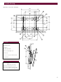
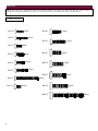
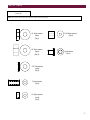
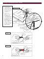
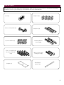
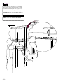
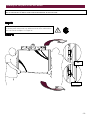
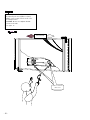
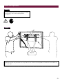
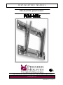
INSTALLATION
MANUAL
Universal flat-panel mount
R
LISTED
E176225
3130 E. Miraloma Ave. Anaheim, CA 92806 Phone: 800 368-9700 Fax: 800 832-4888
www.mounts.com
PREMIER MOUNTS ©2004/ REV 02
Contents
-
Assembly drawing
Fine tune tilt adjustments
Flat panel list
Parts list
Checking thread depth
Finding the center of the flat panel
Positioning the mounting brackets
Securing the mounting brackets
Finding the wood stud behind the wall structure
Marking the bottom plate mounting points
- Securing the bottom wall plate
- Securing the top plate
- Securing the flat panel to the wall mount
- Lateral shift adjustment
The wall structure should be capable of supporting a max weight of 160 Lbs., the weight of the flat panel. More than 160
Lbs the wall must be reinforced. Proper installation procedure by qualified personnel as outlined in the installations
instructions must be adhered to. Failure to do so could result in serious personal injury.
WARNING: Safety precaution measures must be practiced at all times during the installation of this product. Use proper
safety gear and tools for the installation procedure to prevent personal injury.
The entire installation instructions should be fully read and understood, including all of the safety symbols and safety precautions,
before beginning installation. The installation instructions should be read, understood and followed to prevent personal injury or
property damage. Keep these installation instructions in an easily accessible location for future reference.
Indicates that the power plug is to be disconnected from
the power outlet.
Contact Premier Mounts for any questions
Safety precautions must be taken at all times.
Warning and caution in general
A secured structure wooden stud wall must always support the weight or load of the flat panel. Always confirm the
center of the wood stud before beginning the installation.
Do not install in locations where there is vibration, movement or danger of impact. Failure to do so could result in flat
panel cracking or falling from the wall causing damage and injury.
Do not install near heater, fireplace, direct sunlight or air conditioning or any other source of direct heat energy.
Failure to do so may result in damage to the flat panel and could cause a risk of fire.
At least two qualified people should always perform the installation work. Injury and damage can result from dropping
or mishandling the flat panel.
Mounting structure recommended wood studs, solid-flat concrete. Use a minimum diameter of 5/16” x 2 ¼” lg
concrete wedge anchors (commercially available). or a minimum diameter of 5/16” x 3” lg wood screws.
-2-
Assembly drawing
Dimensions are in Inches and (mm)
28.000
(171.2)
16.000
(406.4)
1.245
(31.75)
A
CL
B
H
5.000
(127)
19.000
(482.6)
12.000
(304.8)
10.500
(266.7)
CL
21.000
(533.4)
5.000
(127)
C
G
16.000
(406.4)
D
16.000
(406.4)
16.000
(406.4)
F
24.290
(616.97)
E
Description
2.331
(59.21)
A. Wall plates
G
B. Mounting brackets
C. Griplate™
H
D. Mounting hardware
E. M6 x 30 (mm) Phillip screws
1
F. Wood stud
G. 5/16” x 3” Lag screws and flat washers
H. Safety knobs
Fine tune tilt adjustments
1.
2.
20.500
(520.7)
2
M5 Phillips screws for fine
tension
M8 Hex nut coarse tension
NOTE: The 8 (mm) hex nut is for your
coarse tension adjustment and the 5 (mm)
screws are for your fine tension adjustment.
-3-
Flat panel list
Acer
Eizo
Idex
PDP7859: M6 x 20
5420T: M8 x 30
PDM4260: M4 x 16
Electrograph
Ikegami
DTS42W: M8 x 30 – ¼” nylon spacers (large)
DTS4230: M8 x 30 – ½” nylon spacers - sleeves
DTS42DD, DTS42GBDD, DTS42GB: M6 x 20
PTM4202: M5 x 20
Faroudja
Integra
FPP42HD10, FPP50HD10: M4 X 16
PLA50V1: M4 X 16
Akai
CTA42AR7A, PDP4247, PDP4290, PDP4294,
PDP5090, HPT500AN: M8 x 25 – ½” nylon spacers sleeves
Akira
EPM420, SV4201: M5 x 16
Albatron
PWV46AC: M6 x 20
Barco
Cineversum 50: M8 x 20
BenQ
PDP7843E: M6 x 20 – ¼” nylon spacers (small)
PDP46W1: M6 X 12
Cornea
MP4200, MP4204: M5 x 16
Dream Vision
Revolution One, Revolution Five: M4 x 16
Dukane
P37: M6 x 12
P42: M6 x 12
P50: M8 x 20
Dwin
HD50: M8 x 30 – ½” nylon spacers - sleeves
EIKI
PLD42XU: M5 x 20 - ¼” nylon spacers (small)
Fujitsu
JVC
4211, 4212, 4221, 4222, 4208, 4209, 4213, 4214, 4229,
4241 4242, 4233: M5 x 16
5001, 5002, 5003, 5004, P50XHA10, P50XCA11UH,
P50XHA30WS: M8 x 25 – flat washers
PDS6101, PDS6001, PDS6002: M8 x 30 – ½” Nylon
spacers - sleeves
GDV4200PZW, 4210, GDV4210PZWGA, 4211,
GMP420UG, GMV42UG, JVP042WV74, PD42WV74,
PD42WX84: M5 x 16
GDV500PZU, GDV501U, 502U: M8 X 30 – ½” nylon
spacers – sleeves
Gateway
LG Electronics
GTWP42M102: M8 x 20, M8 x 35 – ¼” nylon spacers
(large)
GATEWAY 42: M8 x 30 – ¼” nylon spacers
GATEWAY 46: M6 x 20
GATEWAY 50: M8 x 30 – ¼” nylon spacers
Flatron MU40PA10B, MU40PA15B: M5 x 20- ¼” nylon
spacers
Flatron MN42PZ10, MN42PZ11, MU42PZ10,
MU42PZ11B, MU42PZ15B: M5 x 20
MU50PZ41, MU50PZ90: M5 x 20
Flatron MU60PZ10, MU60PZ11B, MU60PZ12B,
MU60PZ90V: M8 x 25
Helios
4200: M8 x 20
Hitachi
32HDT20,CMP307XJ,CMP307XU,32HDT20
CMP401HDU, CMP402HDE, CMP402HDU,
CMP4120HDU,CMP4121,CMP4121HDU,CMP4201U,
CMP4202U, 42HDW10,42HDT20, 42HDT50, 42HDT55
M6 x 12
CMP5000WXU, CMP5003WXU, 50HDT50, 50HDT55:
M8 X 20
Luce
PDTV4220A: M5 x 25 – ½” nylon spacers
Marantz
PD4280D, PD4282D, PD4290D, PD4292D,
PD4293: M4 x 20
PD4298HD: M6 X 20
PD501OD, PD5020, PD5040:
Max
4600, 4600T: M6 x 20
5000: M8 x 30- ½” nylon spacers - sleeves
NOTE: If your flat panel display is not listed, go to (page 8) to determine the thread pitch for your flat panel.
-4-
Mitsubishi
Princeton Graphics
Tatung
PD5010HD, PD5030: M4 x 16
AR3.4FTW,AR4.6PDP: M6 x 20
P46T: M6 x 20
Monivision
Rainbow
Toshiba
PWV46AC, PD46W00: M6 x 20
Spectrum 3750: M6 x 20
42HP82: M4 X 16
PD42W, PD42W1: M8 X 30 – ½ ” nylon spacers
(large) - sleeves
50HP81: M8 X 30 – ½” nylon spacers (large) - sleeves
50HP82: M4 X 16
NEC
4200W, 4210W, M4A,MP2, PX42M3A, 42PD1W, PD2
M5A,M5G, 42MP1, 42PD1, PX42VM1A, PX42VP1A,
PX42VP2A, 42MP3, 42PD3, PX42VP3A, 42MP4,
42VP4A, 42MX2: M4 X 16, 5000W, PX50M5A, 50PD1,
PX50VP1A, PX50MX1A, 50MP1, 50MP2, 50PD2,
50VP2, 50MP3,
50XM3: M4 X 16
Norcent
46WGA850: M6 x 12
Orion
RCA
PR42300, PHD42600, PHD50300, PHD50400: M4 X 16
PHD50500: M8 X 20
Revox
E1042: M6 x 20
E1050: M8 x 20
Runco
PL42C, CW42: M4 X 16
PL42CXPL50CX: M8 X 30, ½” Nylon spacers –
sleeves
E1050, PL50C, PL50HDX, CW50MC: M8 X 20
PM4202: M5 x 16
Sampo
Panasonic
PME42S6: M8 x 30 – ¼” nylon spacers (large)
PME42F61: M8 x 20, M8 x 35 – ¼” nylon spacers
(large)
PME50X6: M8 x 30 – ¼” nylon spacers (large)
TC42P1, PT42PD3P, PT42PD1P, TC42P1F, PT37P1,
TH42PWD3, TH37PWD4UZ, PT37PD4, TH37PW5EX,
TH37PA20UP, TH42PD4UY, TH42PWD4EX, PT42P1,
42PD2, TH42PWD3U, TH42PHD5U, PT42PD3P,
PT42PD4, PT42PHD4P, TH42PWD5UY, TH42PW5UZ,
TH42PWD6UY, TH42PA20UP, TH42PL20E,
TH42PAX20, TH50PHD3U, PT50PD3P, PT50PHD4P,
TH50PHD3E, TH50PHW3, TH50PD4, TH50PHD5UY,
TH50PHD6UY, TH50PL20E, TH50TX20UP:
M8 X 30 – ½” Nylon spacers – sleeves
TH42PX20U, TH50PX20U: M8 X 70 – 1-1/2” Nylon
spacers
Samsung
PPM42S2, PPM42S3, SPL4225K, SPN4235, SPN4239:
SPK4215M, PK42P2S: M8 x 25 – ½” nylon spacers
PPM50H2, HPL5025K: M8 x 30 – ½” Nylon spacers sleeves
PPM50H3, HPN5039: M8 x 25 – ½” nylon spacers
Sanyo
Philips
PDP421A: M5 x 20 - ¼” nylon spacer (small)
PDP42H1NA: M5 x 20 - ¼” nylon spacer (small)
42FD9934, 42FD9952, 42FD9954, 42PH9555,
42FD9935: M5 x 25 ½” Nylon spacers
BDS4611: M6 x 20
50FD9934/17S: M4 X 16
Sharp
Pioneer
PDPV401, V402, PDP4330HD, PDP433HDE,
PDP433CMX, PDP433PU, PDP4300, PDP4340HD,
PRO800HD, PRO800HDI, PRO910HD, PDP4310,
PDP501X, V502MX, V502X, PDP503MX, V505,
PDP505HD, PRO1000HD, PDP503CMX, PDP5030HD,
PDP503HDE, PDP5031HD, PDP5040HD,
PRO1000HDI,PRO1110HD: M8 X 20
Planar
42N: M4 x 16
50P: M8 x 20
Tredex
TXP4600: M6 x 20
V-Inc
Vizio P1, Vizio P4: M6 x 12
Vidikron
VPW420: M8 X 30, ½” Nylon spacers (large) - sleeves
VIEWSONIC
VPW420: M8 x 30 – ½” nylon spacers - sleeves
VPW425: M8 x 30 – ¼” nylon spacers (large)
VPW450HD: M8 x 30 – ¼” nylon spacers (large)
VPW500: M8 X 20
VPW505: M8 x 30 – ¼” nylon spacers (large)
Yamaha
PDM1: M8 x 30 – ½” nylon spacers - sleeves
Zenith
DPDP40W, P40V22,DPDP40V, P40V24: M5 x 20 – ¼”
nylon spacers (small)
P42W22, P42W22B, P42W24P, P42W34P: P40V24:
M5 x 20 – ¼” nylon spacers (small)
P50W26, P50W28, P50W38: M5 x 16
NOTE: If your flat panel display is not
listed, go to (page 8) to determine the
thread pitch for your flat panel.
PZ42H2U, PZ43HV2U, PD50U, PZ50HV2U: M8 X 20
SONY
PFM42B1,PFM42B2: M6 x 20 - 5/16” flat washers
PFM-42V1,PFM-42V2: M6 x 20”- 5/16” flat washers
PFM50C1: M5 x 20 - 5/16” flat washers
KE-42XBR900: M5 x 20 - 5/16” flat washers
KE50XBR900: M5 x 20 - 5/16” flat washers
KE42XS910: M5 x 20 - 5/16” flat washers
KDE61XBR950: M5 x 20 - 5/16” flat washers
SVA
HD4208TIII: M6 x 20 - ¼” nylon spacers
-5-
Parts list
NOTE: This wall mount is shipped with all proper installation hardware and components. Make sure that none of these parts are
missing before beginning installation. If there are parts missing stop the installation and contact Premier Mounts.
Actual screw size
M4 x 16
(Qty 8)
M6 x 20
(Qty 6)
(Qty 4)
M4 x 25
(Qty 2)
M6 x 30
M5 x 12
M5 x 16
M5 x 20
(Qty 8)
M8 x 20
(Qty 6)
(Qty 6)
M8 x 25
M8 x 30
M5 x 50
(Qty 6)
(Qty 4)
(Qty 8)
M8 x 35
M8 x 70
-6-
(Qty 6)
(Qty 4)
M5 x 25
M6 x 12
(Qty 6)
(Qty 4)
(Qty 4)
Parts list (con’t)
Nylon spacers and flat washers
actual size
NOTE: The nylon spacers may be staked to achieve proper spacing.
1/4" Nylon spacers
(large)
(Qty 6)
1/2" Nylon spacers
(large)
(Qty 12)
9/16" Nylon spacers
(Qty 6)
Nylon sleeves
(Qty 4)
5/16" Flat washers
(metal)
(Qty 6)
1" Nylon spacers
(Qty 6)
1/4" Nylon spacers
(small)
(Qty 6)
-7-
Checking the thread depth on your flat panel
1.
2.
Insert the thread depth
indicator (supplied)
through the thread inserts
found on the back of the
flat panel to make sure the
inserts measure the same
full depth and mark it.
(see figure 1)
Locate the correct
diameter screw for the
thread insert. Compare
your marking to the
screws (supplied). If your
selected screw is longer
than the marking on the
thread depth indicator DO
NOT USE this screw.
The screw length must not
bypass the marking. Select
another screw size
(see figure 2 and 3). Until
you find one that comes
closest to your mark
without going past.
Figure 1
Inverted flat panel
display
Marking the depth
Thread insert
Thread depth
indicator
Figure 2
Screw
Marking
Thread depth indicator
Figure 3
Screw
Marking
-8-
Thread depth indicator
Parts list (con’t)
All of these parts are used to install the mounting bracket. Make sure that none of these parts are missing before beginning
installation. If there are parts missing stop the installation and contact Premier Mounts.
Level (1)
Griplates™ (8)
M6 x 12 Safety knobs (2)
Wall plates (2)
5/16" flat washers (8)
5/16" x 3" Lag bolts (8)
(used on wood studs
only)
Template (1)
Mounting brackets
(left & right)
M6 x 30 Lateral shift
locking screws (2)
Thread depth
indicator (1)
-9-
Finding center of the flat panel display
WARNING : Proper installation procedure by qualified personnel as outlined in the installation instructions must be adhered to. Failure to do so could
result in serious personal injury and possible damage to the flat panel.
WARNING!
INVERT THE FLAT PANEL PLACE IT ON A SOFT, FLAT SUFRACE TO PREVENT DAMAGE TO THE FLAT PANEL. USE A BLANKET, FOAM, ETC. FAILURE TO
DO SO WILL RESULT IN DAMAGING THE FLAT PANEL. DO NOT LAY THE FLAT PANEL ON THE FLOOR WITHOUT ANY PROTECTION TO THE GLASS. THE
FLAT PANEL IS HEAVY AND FRAGILE. AT LEAST (2) QUALIFIED PERSONNEL ARE STRONGLY RECOMMENDED FOR INSTALLATION OF THIS PRODUCT.
FAILURE TO DO SO COULD RESULT IN SERIOUS INJURY AND POSSIBLE DAMAGE TO THE FLAT PANEL.
Once the flat panel is inverted, use a measuring
tape to find the center of your flat panel measuring
from outside to outside of the chassis. See figure 1.
Top of flat
panel
CL
Measuring
tape
Inverted flat panel
Bottom of flat
panel
Using a pencil lightly mark the center of your flat
panel.
See figure 2.
Inverted flat panel
Mark the center of
the flat panel
- 10 -
CL
Positioning the mounting brackets
Nylon spacers if
Applicable
(see chart) on page 4 and 5
CAUTION: Check the chart on page 4 and 5 to see if
your flat panel needs nylon spacers. The nylon spacers
provided, must be used. Failure to do so will result in
damaging the flat panel.
Install the nylon spacers to the mounting points on the
flat panel see figure 3.
NOTE: See chart (if the nylon spacers apply to your
flat panel).
Center mark
Inverted flat panel
Lay the left and right mounting
brackets (stamped arrows facing out).
See figure 4.
Mounting brackets
Bottom of flat
panel
Arrows facing out
- 11 -
Match the center of viewing guide with the center
line you marked in step 1.
See figure 5.
CL
Bottom of flat
panel
Align the
mounting brackets
Mounting bracket
The mounting brackets are designed with a center
of viewing guide on the side of them.
See figure 6.
Bottom of flat
panel
Center of flat
panel
- 12 -
Center of
viewing guide
Securing the mounting brackets
The Griplates™ have M4, M5 M6 and M8 hole
patterns to fit the hardware that your flat panel
requires.
DIMPLES
M8
EXAMPLE: If your plasma uses M8 x 20 Phillip
screws. Use the M8 mounting points. See figure 7
M6
Pre install two (2) M6 x 30 (mm) Phillip pan screws to
the bottom of the left and right hand side mounting
brackets. Once the mounting brackets are aligned secure
the Griplate™ to the flat panel.
M5
NOTE: The dimples of the top plates have to be facing
up and the bottom dimples must be facing down.
Use (1) Griplate™ per mounting point. See figure 8.
M4
Phillips screw
driver
DIMPLES
FACING UP
DIMPLES
FACING UP
DIMPLES
FACING DOWN
Bottom of flat
panel
DIMPLES
FACING DOWN
CAUTION: Do not over tighten the mounting
hardware.
NOTE: Secure the two (2) M6 x 30 Phillip pan
screws to the left and right mounting bracket.
- 13 -
Finding the wood studs behind the wall structure
Using a (commercially available) wood stud finder,
locate the 16" or 24" stud centers behind the wall.
Once found, make a pencil marking on the center of
the wood studs.
See figure 9.
Wood stud finder
(commercially available)
Mark the wall and
the center of the
wood studs.
NOTE: The wall plates have (3) 16" and (1)
24" mounting slot positions.
(Look at the assembly drawing on page 3)
CENTER OF VIEWING HEIGHT DESIRED
16"
Wood studs
behind the wall
structure
Center of
viewing port
16"
16"
Align the center viewing port from the carton template to
the center of the wood studs horizontally. Match the
center of viewing port to the center of viewing height
desired and mark a line on the bottom of the carton
template.
See figure 10.
- 14 -
CENTER OF VIEWING HEIGHT DESIRED
Mark the
bottom of the
carton template
Carton
template
Center of
viewing mark
Marking the bottom plate mounting points
Place the upper portion of the bottom wall plate to the
reference line and mark the four (4) lag bolt mounting points
through the wall plate slots on the wall. Level the wall plate
with the reference arrow pointing up to the ceiling.
See figure 11.
Wall
Wall plate
plate
16"
Mounting
slots
Wood
Wood studs
studs
Drill gun
Level
Pilot holes
Drill four (4) ¼" pilot holes to the marked
wall.
See figure 12.
16"
- 15 -
Securing the bottom wall plate
Level
Level and secure the plate to the wall with
the reference arrow facing up to the ceiling.
Secure the plate using the four (4) 5/16" lag
bolts and flat washers (supplied). See figure
13.
CAUTION: Do not over tighten the lag bolts.
Wall plate
(4) 5/16" x 3" lag bolts
and (4) flat washers
(supplied)
Marked wall
When the bottom wall plate is properly
installed to the wall. Lay the carton template on
top of the wall plate.
Lay the top wall plate on top of the cardboard
template and mark the four (4) lag bolt
mounting points.
See figure 14.
Template
Wall plate
- 16 -
Securing the top plate
Drill four (4) ¼" pilot holes to the
marked wall. See figure 15.
Wall marks
Wall plate
- 17 -
Level and secure the plate to the wall with
the reference arrow facing up to the ceiling.
Secure the plate using the four (4) 5/16" lag
bolts and flat washers (supplied). See figure 16
CAUTION: Do not over tighten the lag bolts.
NOTE: CHECK THE MOUNT FOR PROPER
TIGHTNESS AND SECURITY.
Power source
area
Wall plates
- 18 -
Securing the flat panel to the wall mount
WARNING: AT LEAST (2) QUALIFIED PERSONNEL ARE STRONGLY RECOMMENDED FOR INSTALLATION OF THIS PRODUCT. FAILURE TO
DO SO COULD RESULT IN SERIOUS INJURY AND POSSIBLE DAMAGE TO THE FLAT PANEL.
Raise the flat panel with the LEFT and RIGHT mounting brackets secured
to the flat panel and insert the top and bottom hooks from each bracket to
the rods from the wall plates. See figure 17.
TOP
BOTTOM
- 19 -
Make any lateral shift adjustment and lock it
by tightening the two (2) M6 x 30 (mm)
Phillips screws found on the bottom of the
mounting brackets.
CAUTION: Do not over tighten the M6
screws to the rods.
See figure 18
Lateral shift
M6 x 30 Lateral
shift screw
- 20 -
Lateral shift adjustment
Tilt the flat panel and secure the two (2) M6 x 12 (mm)
safety knobs to each of the mounting brackets.
See figure 19.
M6 x 12
Safety knobs
NOTE: To remove the display from the wall simply extend the display to its maximum tilt range, remove the two 6 (mm) safety
knurl knobs push the flat panel back to it’s flat position loosen or remove the two (2) M6 x 30 lateral shift screws and lift the
unit of the wall.
- 21 -
www.mounts.com
NORTH AMERICA
EUROPE
ASIA
3130 East Miraloma Avenue
Anaheim, CA 92806 USA
USA and Canada –
Phone: 800-368-9700
Fax: 800-832-4888
Swallow House,
Shilton Industrial Estate,
Shilton, Coventry, England CV79JY
Phone: +44 (0) 2476 614700
Fax: +44 (0) 2476 614710
Yabara 1916-15,
Misato-machi, Gunma-gun
Gunma-ken 370-3107, Japan
Phone: 81.27.371.6998
Fax: 81.27.371.6308
Other Locations – Phone: 001.714.632.7100; Fax: 001.714.632.1044
©Premier Mounts 2004
- 22 -