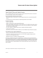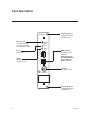
1
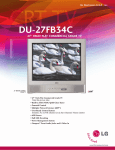
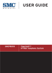
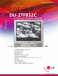
HCS6600 CodePlus™ Series Cable HD Transcoder MPEG-2 Installation & Setup Guide Warranty © Copyright 2010, LG Electronics U.S.A., Inc. Part No: 206-4119 For Customer Support/Service, please call: 1-888-865-3026 The latest product information and documentation is available online at: www.LGcommercial.com/products WARNING RISK OF ELECTRIC SHOCK DO NOT OPEN WARNING: TO REDUCE THE RISK OF ELECTRIC SHOCK DO NOT REMOVE COVER (OR BACK). NO USER-SERVICEABLE PARTS INSIDE. REFER TO QUALIFIED SERVICE PERSONNEL. ALL CARDS MUST BE INSERTED AND REMOVED BY QUALIFIED SERVICE PERSONNEL ONLY. The lightning flash with arrowhead symbol, within an equilateral triangle, is intended to alert the user to the presence of uninsulated “dangerous voltage” within the product’s enclosure that may be of sufficient magnitude to constitute a risk of electric shock to persons. The exclamation point within an equilateral triangle is intended to alert the user to the presence of important operating and maintenance (servicing) instructions in the literature accompanying the appliance. WARNING: TO PREVENT FIRE OR SHOCK HAZARDS, DO NOT EXPOSE THIS PRODUCT TO RAIN OR MOISTURE. Apparatus shall not be exposed to dripping or splashing and no objects filled with liquids, such as vases, shall be placed on the apparatus. L’appareil ne doit pas être exposé à des égouttements d’eau ou des éclaboussures et de plus qu’aucun objet rempli de liquide tel que des vases ne doit être placé sur l’appareil. REGULATORY INFORMATION: This equipment has been tested and found to comply with the limits for a Class A digital device, pursuant to Part 15 of the FCC Rules. These limits are designed to provide reasonable protection against harmful interference when the equipment is operated in a commercial environment. This equipment generates, uses and can radiate radio frequency energy and, if not installed and used in accordance with the instruction manual, may cause harmful interference to radio communications. Operation of this equipment in a residential area is likely to cause harmful interference in which case the user should be required to correct the interference at his own expense. CAUTION: Do not attempt to modify this product in any way without written authorization from LG Electronics U.S.A., Inc. Unauthorized modification could void the user’s authority to operate this product. COMPLIANCE: The responsible party for this product’s compliance is: LG Electronics U.S.A., Inc. 2000 Millbrook Drive, Lincolnshire, IL 60069, USA • Phone: 1-847-941-8000 Marketed and Distributed in the United States by LG Electronics U.S.A., Inc. 2000 Millbrook Drive, Lincolnshire, IL 60069 2 © Copyright 2010, LG Electronics U.S.A., Inc. 206-4119 IMPORTANT SAFETY INSTRUCTIONS Important safeguards for you and your new product THIS PRODUCT HAS BEEN MANUFACTURED AND TESTED WITH SAFETY IN MIND. IMPROPER USE, HOWEVER, CAN RESULT IN POTENTIAL ELECTRICAL SHOCK OR FIRE HAZARDS. TO AVOID DEFEATING THE SAFEGUARDS THAT HAVE BEEN BUILT INTO THIS PRODUCT, PLEASE READ AND OBSERVE THE FOLLOWING SAFETY POINTS WHEN INSTALLING AND USING THIS PRODUCT. 1. Read these instructions. Read all the safety and operating instructions before operating the product. 2. Keep these instructions. Retain the safety and operating instructions for future reference. 3. Heed all warnings. Adhere to all warnings on the product and in the operating instructions. 9. Outdoor Use Warning: To prevent fire or shock hazards, do not expose this product to rain or moisture. 10. Wet Location The apparatus shall not be exposed to dripping or splashing and no objects filled with liquids, such as vases, shall be placed on the apparatus. 6. Clean only with dry cloth. Unplug this product before cleaning. Do not use liquid cleaners or aerosol cleaners. 11. Test Equipment In some cases, LG has supplied or recommended the use of test equipment and devices for the setup and testing of the equipment. The operation and maintenance of test equipment is described in their associated instruction manuals. Please refer to these manuals for explicit instructions regarding the safe use and handling of the equipment. 7. Refer all servicing to qualified service personnel. Servicing is required when the apparatus has been damaged in any way, liquid has been spilled or objects have fallen into the apparatus, the apparatus has been exposed to rain or moisture, does not operate normally, or has been dropped. 12. Replacement Parts When replacement parts are required, be sure the service technician uses replacement parts specified by the manufacturer or that have the same characteristics as the original parts. Unauthorized substitutions may result in fire, electric shock, or other hazards. 4. Follow all instructions. Follow all operating and use instructions. 5. Do not use this apparatus near water. Do not use this product near water or moisture or in an area, such as a basement, that might become flooded. 8. Object and Liquid Entry Never push objects of any kind into this product through openings as they may touch dangerous voltage points or short-out parts that could result in a fire or electric shock. Never spill liquid of any kind on the product. 206-4119 (Continued on next page) 3 IMPORTANT SAFETY INSTRUCTIONS (Continued from previous page) 13. Damage Requiring Service Unplug this product from the wall power outlet and refer servicing to qualified service personnel under the following conditions: a. If liquid has been spilled, or objects have fallen into the product. b. If the product has been exposed to rain or water. c. If the product does not operate normally by following the operating instructions. Adjust only those controls that are covered by the operating instructions, as an improper adjustment of other controls may result in damage and will often require extensive work by a qualified technician to restore the product to its normal operation. d. If the product has been dropped or the cabinet has been damaged. e. If the product exhibits a distinct change in performance. 14. Servicing Caution: These servicing instructions are for use by qualified service personnel only. To reduce the risk of electrical shock, do not perform any servicing other than that described in the operating instructions unless you are qualified to do so. 15. Safety Check Upon completion of any service or repairs to this product, ask the service technician to perform safety checks to determine that the product is in proper operating condition. Caution: Refer all servicing to qualified service personnel. 4 206-4119 Table of Contents / Setup Information Table of Contents Safety Warnings . . . . . . . . . . . . . . . . . . . . . . . 2 Important Safety Instructions. . . . . . . . . . . . 34 Table of Contents / Setup Information. . . . . . . 5 HCS6600 Product Description . . . . . . . . . . . . 6 Transcoder Product Description . . . . . . . . . . . 7 Card Description . . . . . . . . . . . . . . . . . . . . . . . 8 Installing CodePlus Transcoder Cards . . . . . . . 9 Cable TV STB Receiver & HCS6600 Initialization & Setup Connections . . . . . . . . . 10 System Setup . . . . . . . . . . . . . . . . . . . . . .1112 Configuration Options . . . . . . . . . . . . . . . 1315 Troubleshooting . . . . . . . . . . . . . . . . . . . . . . . 16 Specifications . . . . . . . . . . . . . . . . . . . . . . . . 17 Document Revision History / Notes . . . . . . . 18 Warranty . . . . . . . . . . . . . . . . . . . . . Back Cover Setup Information This document provides installation and setup support only for an HCS6600 transcoder card. Cable TV service and a Cable TV STB receiver must be installed and operating before you can proceed to set up the HCS6600. LG recommends that the system be professionally installed. Check the items listed below before you begin the HCS6600 installation and setup procedures. Cable Set-top Box (STB) __ Refer to the documentation provided with the Cable TV STB, and carefully follow the system setup procedures. (The Cable TV STB receiver provides the IEEE-1394 signal input for the HCS6600.) __ Authorization is required for HD channels. Contact your local Cable TV provider to get subscription programming authorization for the Cable TV STB receiver. HCS6600 __ If the HCS6600 will be used with a unique feature card (Example: HCS6300) in the card frame CONTROLLER slot, you will also need a copy of the Installation & Setup Guide for the feature card in order to complete the HCS6600 system setup. __ For HCS6600 Service Port connections, you must use an FTDI TTL-USB cable (P/N TTL232R-5V-AJ). ASI Output (Optional) __ If applicable, install the DTV modulator and upconverter that will receive the ASI output signal from the HCS6600. Refer to the manufacturer's documentation. 206-4119 5 HCS6600 Product Description The HCS6600 is one of the LG CodePlus™ series of transcoder cards. Pairing an HCS6600 card, in the appropriate CodePlus card frame, with a suitable Cable TV STB receiver will provide one channel of Cable TV content. Features • Part of modular system, easily scaled for each application • Transcodes Cable DTV content to ATSC-compatible MPEG-2 • Built-in Pro:Idiom® content protection • DVB-ASI output available to connect to external MUX or modulator • Transcoded output supports Closed Captions and V-Chip (Parental Control) * • Short 3U height profile to minimize rack-space usage HCS6600 SERVICE PORT RESET STATUS I 1 E 3 E 9 E 4 B I E E E 10 1 3 9 4 A ASI OUT * If included in the signal source. 6 206-4119 Transcoder Product Description Typical Cable HD Transcoder System Overview The LG HCS6600 Cable HD transcoder represents a single-channel HDTV solution for commercial and institutional MATV systems (hotels, hospitals, etc.). A typical Cable HD Transcoder system includes: • An HCS6600 Cable HD transcoder for each HD program offered in the commercial facility MATV system. • A CodePlus series card frame (Example: HCS6100R) specified for the HCS6600. Purchased separately: • Cable TV service feed. • Cable TV STB receiver for each transcoder/HD program. • VSB or QAM modulator with ASI input (for each transcoder) or LG CodePlus-series unique feature card (Example: HCS6300). Multiplexers can be used in front of the modulator if multiple programs are desired and 256-QAM is used. • (For each modulator, if applicable) Upconverter compatible with digital modulation. • 19-inch rack for mounting. • Miscellaneous cables and installation hardware (see also HCS6600 setup information on page 5). The elements of such a system combined can: • Receive a selected HD channel from Cable TV service using a Cable TV STB receiver. • Transcode the digital video and audio stream to an ATSC A/53E compatible transport stream. • Encrypt the received digital data stream. • Modulate the stream in 64-QAM or multiplexed 256-QAM. A Pro:Idiom-compatible television with a QAM/VSB tuner is required to view premium HD content. The HCS6600 changes the Cable TV encryption scheme to a Pro:Idiom encryption scheme. A proper session ID must be set at the TV in order for Pro:Idiom decryption to be enabled. LG’s Pay-Per-View (PPV) partners can properly set up this session through their interface. An LG Free-to-Guest (FTG) card is substituted for the supplied Multiple Protocol Interface (MPI) card and can set the session to allow decryption. Note: Design and specifications subject to change without prior notice. 206-4119 7 Card Description HCS6600 Service Port TTL-USB serial port connection (use FTDI TTL-232R-5V-AJ cable) Retaining Screw Install after inserting HCS6600 card SERVICE PORT RESET STATUS Reset Reboots card I E E E 1 3 9 4 B Status Blinking pattern indicates condition of card I E E E 1 3 9 4 A 10 IEEE-1394 In To Cable TV STB 1394 Out Note: Always use the IEEE-1394A port for the Cable TV STB connection. ASI Out DTV signal output ASI OUT Retaining Screw Install after inserting HCS6600 card 8 206-4119 Installing CodePlus Transcoder Cards Slots 3&4 Slot 1 Slot 2 HCS6600 SERVICE PORT SERVICE PORT I E E E 1 3 9 4 A I E E E ASI OUT 1 3 9 4 A ASI OUT 1 3 9 4 B I E E E 1 3 9 4 A 10 HCS6600 SERVICE PORT SERVICE PORT HCS6600 HCS6600 HCS6600 I E E E SERVICE PORT RESET 1 3 9 4 A STATUS RF OUT I 1 E 3 E 9 E 4 B I E E E ASI OUT I 1 E 3 E 9 E 4 B 1 3 9 4 A I E E E HCS6600 ASI OUT I E E E ASI OUT 1 3 9 4 A I E E E ASI OUT I E E E ASI OUT STATUS STATUS I 1 E 3 E 9 E 4 B I 1 E 3 E 9 E 4 B 1 3 9 4 A RESET RESET STATUS I 1 E 3 E 9 E 4 B SERVICE PORT SERVICE PORT RESET STATUS I 1 E 3 E 9 E 4 B 1 3 9 4 A SERVICE PORT SERVICE PORT RESET STATUS STATUS STATUS I 1 E 3 E 9 E 4 B SERVICE PORT RESET RESET RESET STATUS I E E E HCS6600 ETHERNET RESET STATUS I 1 E 3 E 9 E 4 B HCS6300 Slot 9 Slot 10 Slot 11 Slot 12 Slot 8 Slot 7 Slot 6 SERVICE PORT RESET STATUS Slot 5 HCS6600 HCS6600 RESET I 1 E 3 E 9 E 4 B HCS6600 CONTROLLER Slot 1 3 9 4 A I E E E ASI OUT 1 3 9 4 A ASI OUT ASI OUT CONTROLLER Slot The card in this slot may vary depending on system features. Note: All cards used in the card frame must be inserted and removed by qualified service personnel only. 1. Unpack the HCS6600 unit(s) and all accessories. Accessories provided: IEEE-1394 Cable (Length = 1 meter) Note: Use extreme care when handling an 2. Select the slot(s) in the card frame in which to HCS6600 card. Always observe proper install the HCS6600. Note: All cards must be precautions with respect to static electricused in an LG-approved card frame for this ity and mechanical shock. When not installed product. in a card frame, return the HCS6600 card to the anti-static bag in which it was shipped. 3. Remove the AC power cord for the card frame from the power outlet. Note: The CodePlus series products are NOT designed to be hot-swappable!!! 4. Remove the blank cover plate from each slot Power must be removed to the card into which a card is to be inserted. frame before any CodePlus transcoder cards 5. Without using force, slide each new card into are inserted or removed. its designated slot, and ensure that it is fully Note: The card slots in the card frame inserted. are NOT all identical!!! An HCS6600 card can only be installed in Slots 1 to 6 and 7 to 12. The CONTROLLER slot between Slots 6 and 7 is dedicated for optional feature cards and is not compatible with HCS6600 cards. Note: When installing cards, remove blank cover plates and insert new cards as applicable. For ports that will not be used, leave the blank cover plates in place for proper ventilation and FCC and safety agency compliance. 206-4119 6. Engage and tighten the top and bottom thumbscrews securely. Note that the thumbscrews should only be finger tight; overtightening may damage the assembly. 7. Refer to the diagram on page 10 for cable connections, and complete the system installation and test procedure on page 11. 9 Cable TV STB Receiver & HCS6600 Initialization & Setup Connections Power Outlet (120V 60Hz AC) Cable TV STB E LLIT SATESW1 AV OUT O ON O L/M IO-AUD IN ..... ..... LANONLY) ICE (SERV 1 3 9 4 Laptop PC RF Feed from Cable TV Provider .......... TTL-USB Service Port Connection R VIDE Composite Video and L/R Audio to NTSC Monitor 1394 Link HCS6600 In Card Frame Chassis HC S6 60 0 HCS66 00 HCS66 00 HCS670 0 SERVICE PORT RESET I 1 E 3 E 9 E 4 B SERVICE PORT RESET STATUS I 1 E 3 E 9 E 4 B I 1 E 3 E 9 E 4 A X-PORT STATUS Service Port I 1 E 3 E 9 E 4 A ASI OUT Reset Status Link Reset ASI OUT 10 ASI OUT Se Porvic rt e Re se t St at us SN XXXXXXX MAC ADDRES XX XX S XX XX XX SN XXXXXXX MAC ADDRES XX XX S XX XX XX I 1 E 3 E 9 E 4 A ..... 0 HCS66 00 HCS66 00 Service Port Status ASI OUT MAC ADDRES XX XX S XX XX XX HCS670 Service Reset Status I 1 E 3 E 9 E 4 B SN XXXXXXX HD Chan nel SE R PO VIC RT E ES 8 ET STA TU S 9 R Port ASI OUT ASI OUT 7 HCS66 00 SERVICE PORT RESET I 1 E 3 E 9 E 4 B HCS66 00 SERVICE PORT RESET STATUS I 1 E 3 E 9 E 4 B I 1 E 3 E 9 E 4 A HCS66 00 SERVICE PORT RESET STATUS I 1 E 3 E 9 E 4 B I 1 E 3 E 9 E 4 A SERVICE PORT RESET STATUS I 1 E 3 E 9 E 4 B I 1 E 3 E 9 E 4 A ASI OUT SERVICE PORT RESET STATUS I 1 E 3 E 9 E 4 B I 1 E 3 E 9 E 4 A ASI OUT STATUS I 1 E 3 E 9 E 4 A ASI OUT ASI OUT ASI OUT SN XX MAC XX XX XX ADD X XX RE XX SS XX XX AS IO NTSC Monitor ASI Out from HCS6600 UT AC Power Cord Power Outlet (120V 60Hz AC) RF Distribution Grid Room Receiv er Modulator Combiner Room Receiv er Upconverter Room Receiv er Note: This diagram shows setup connections where a unique feature card is NOT installed in the card frame CONTROLLER slot. 10 Room Receiv er 206-4119 System Setup Typical HCS6600 System Installation & Test (see also Typical Setup Flow Chart on page 12) 1. Verify that the Cable TV STB receiver is set up and functioning (i.e., check that the STB is connected to an NTSC monitor [for tuning purposes], that it is powered up, that initialization is complete, and that the NTSC monitor is displaying the default channel properly—refer to the STB documentation). 2. On the Cable TV STB, tune to the appropriate channel using the controls on the front panel or the IR remote control. 3. Connect the IEEE-1394 cable between the Cable TV STB and the HCS6600 IEEE1394A port. 4. Perform one of the following per your installation: • If the HCS6600 will NOT be used with a unique feature card in the card frame CONTROLLER slot, connect a 75 ohm BNC-to-BNC coaxial cable between ASI OUT on the transcoder and ASI IN on the modulator. Then, continue with step 5. Note: The BNC cable must be less than 30 feet (9.2 meters) in length. 5. If your installation includes a separate modulator and upconverter, connect an RF coaxial cable between IF OUT on the modulator and IF IN on the upconverter, and then check the modulator and upconverter for correct settings (QAM type, channel number, etc.). 6. Repeat steps 1 to 5 for each of the Cable TV STB/transcoder pairs. 7. Plug in power to the CodePlus card frame containing the newly installed HCS6600 card(s). The green Status LED will blink at an approximately 1 Hz rate while the HCS6600 card boots up. The boot-up process for an HCS6600 may take up to two minutes, and there is no ASI output (if applicable) during boot-up. When the boot-up is complete, the green Status LED will be lit continuously. 8. If applicable, connect the RF output on the upconverter to the combiner. 9. Check one or more room receivers to make sure all channels are properly tuned, mapped, and operating. • If the HCS6600 will be used with a unique feature card in the CONTROLLER slot, the cable to the ASI OUT port may not be required. Refer to the Installation & Setup Guide for the feature card for further instruction before you continue this setup procedure. 206-4119 11 System Setup (Cont.) Typical Setup Flow Chart for a Single HD Channel Cable TV Service Feed RF Cable RF In Cable TV STB 1394 Out Access Card A/V Cables (for monitor only) 1394 In HCS6600 Combiner ASI Out ASI IF In ASI In VSB or QAM Modulator IF Out RF Coaxial Cable DTV Upconverter RF Cable NTSC Monitor RF Out Note: This diagram shows setup connections where a unique feature card is NOT installed in the card frame CONTROLLER slot. 12 206-4119 Configuration Options The HCS6600 contains several internal registers for different configuration options. These can either be left at their default values or configured by the user. There are two methods available for configuration purposes: • Service Port Method • Controller Card Method This document describes configuration procedures using the Service Port Method, which requires that you connect a PC directly to the transcoder Service Port. For configuration procedures using the Controller Card Method, refer to the Installation & Setup Guide for the feature card installed in the card frame CONTROLLER slot. Connect a PC to the HCS6600 Service Port and Access the HCS6600 Main Menu 1. Follow the directions in the Installation and Test sections of this manual. The Cable TV STB and the HCS6600 must be installed and operating before you proceed. 2. Connect the PC to the HCS6600 Service Port using the FTDI TTL-USB cable (P/N TTL232R-5V-AJ): • Plug the USB end of the cable into an open USB port on your PC. If necessary, install the device driver. • Plug the other end of the cable into the Service Port jack on the HCS6600 front panel. 3. Using HyperTerminal or an equivalent terminal emulation program on the PC, configure the COM port as follows: • Baud = 115200 • Data bits = 8 • Parity = None • Stop bits = 1 • Flow Control = None Then, initiate communication with the HCS6600. 4. Press Enter to refresh the menu display in the terminal. 206-4119 You now have access to the HCS6600 configuration Main Menu. Refer to the following sections for information on user-configurable options. Disable the Content Advisory Descriptor For legacy systems using LST5600 Set-back Box receivers, it is necessary to disable the Content Advisory Descriptor in the PMT of the HCS6600’s Transport Stream output. All other products will operate normally with the Content Advisory Descriptor enabled. The default setting is Content Advisory Descriptor Enabled. Note: Disabling the Content Advisory Descriptor will disable the Parental Control (V-Chip) feature of all room receivers for this channel. Use the following procedure if you wish to disable V-Chip. 1. Connect your PC to the HCS6600 Service Port, and access the Main Menu as described previously. 2. With the Main Menu on display, type the number corresponding to the Toggle Content Advisory option, and press Enter. The system will print out the new state of the Content Advisory Descriptor option. This state will be stored in non-volatile storage and remain in that state until changed by a user. 13 Configuration Options (Cont.) Change or Renew the Pro:Idiom Encryption Key The Pro:Idiom encrypter built into the HCS6600 contains a default encryption key. When first installed, the HCS6600 will use this key to encrypt content. Note: In order for a Pro:Idiom encrypted channel to be displayed, the following conditions are required: • The receiver must contain a Pro:Idiom decrypter. • The MPI control card in the receiver must be configured to allow decryption of the desired channel. If it becomes necessary to change or renew the encryption key, use the following procedure. 1. Connect your PC to the HCS6600 Service Port, and access the Main Menu as described previously. 2. With the Main Menu on display, type the number corresponding to the Setup PI option, and press Enter. 3. The system will request a key file. Transfer the new Pro:Idiom key file using Xmodem protocol. For example, in HyperTerminal, select Transfer and then Send File.... In the Send File window, enter or select the appropriate Pro:Idiom key file in the Filename field, and select Xmodem in the Protocol field. The system will then print out the result of the update process. Note that the new key will be stored in non-volatile storage regardless of process results. Note: The process of updating the encryption key will synchronize the decryption key in any receiver tuned to this card's output. If the target receiver is turned off or viewing a different card, the synchronization will not occur, and the output will be scrambled. Ensure that all encrypters and decrypters in a system are synchronized to the same key. View the Pro:Idiom Key Checksum Use the following procedure if you wish to display the Pro:Idiom Key checksum. 1. Connect your PC to the HCS6600 Service Port, and access the Main Menu as described previously. 2. With the Main Menu on display, type the number corresponding to the Read PI Key Checksum option, and press Enter. The system will display the following: PI key checksum is xxxxxxxxxx where xxxxxxxxxx identifies the set of Pro:Idiom Key files installed on the transcoder. Note: All transcoder cards in the card frame must have the same Pro:Idiom Key files installed. View System Information Use the following procedure if you wish to display system data, including HCS6600 hardware and software information. 1. Connect your PC to the HCS6600 Service Port, and access the Main Menu as described previously. (Continued on next page) 14 206-4119 Configuration Options (Cont.) (Continued from previous page) 2. With the Main Menu on display, type the number corresponding to the System Info option, and press Enter. The system will display a System Information banner that contains important information about the HCS6600, including the unit serial number, hardware ID (firmware version), and software version. LG suggests that you record this information for future reference. If you find it necessary to call customer service or engineering support, please have this information available. Reset the HCS6600 Use the following procedure if you wish to reset the HCS6600. 1. Connect your PC to the HCS6600 Service Port, and access the Main Menu as described previously. 2. With the Main Menu on display, type the number corresponding to the Reset option, and press Enter. The system resets the HCS6600. During the reset process, several pages of status and diagnostic messages may be displayed. After reset, the HCS6600 resumes normal operation, and the system displays the System Information banner and Main Menu. 1. Connect your PC to the HCS6600 Service Port, and access the Main Menu as described previously. 2. With the Main Menu on display, type the number corresponding to the Update Firmware option, and press Enter. 3. The system will request a configuration (.cfg) file. Transfer the new configuration file using Xmodem protocol. For example, in HyperTerminal, select Transfer and then Send File.... In the Send File window, enter or select the appropriate configuration file in the Filename field, and select Xmodem in the Protocol field. 4. Upon receipt of the configuration file, the system will request a package (.pkg) file. Transfer the package file using Xmodem protocol. This process may take several minutes; please be patient. When the process is complete, the system will report success or failure of the firmware installation. 5. Repeat steps 1 to 4 of this procedure for each HCS6600 card whose firmware you wish to update. 6. Upon successful installation(s), power cycle the system: Unplug the power cord of the card frame for 15 seconds; then plug it in again. Update HCS6600 Firmware Use the following procedure if you wish to update HCS6600 firmware. Note: If you are not sure of the current firmware version, LG recommends that you view and record the System Information (see procedure above) before you initiate the firmware update. 206-4119 15 Troubleshooting Many problems can be corrected with a simple reset of the Cable TV STB and/or the HCS6600. Running the system test on the Cable TV STB receiver can also help you diagnose and solve many common problems. If you experience image freezes, audio freezes, or a blank screen, or the system won’t respond to a front panel button or remote control key presses, try one of these: • Remove and reinsert the cable access card in the Cable TV STB. • If your STB has a RESET button, press it, and then wait for program guide information to be acquired. • Unplug the power cord of the STB for 15 seconds; then plug it in again. • Press the RESET button on the HCS6600 card to reboot it. • Unplug the power cord of the CodePlus card frame for 15 seconds; then plug it in again. Equipment Setup Review • Make sure all connectors and connections are tight and secure on all entertainment system components. • Check the IEEE-1394 connection. • Ensure that the access card is installed, is up-to-date, and has been authorized by the Cable Service provider. • Check that the batteries in the remote control are fresh and that the remote mode selector switch is set on "CATV." Note that only one Cable TV STB should be ON at a time. Status LED The green Status LED on the HCS6600 front panel provides general information about the operating condition of the transcoder. Observe the Status LED, and refer to the following table: Status LED Behavior Operating Status Slow Blinking System Booting Rapid Blinking Ready for Input Continuously On Normal Operation Continuously Off Fault Condition, No Output 16 206-4119 Specifications Dimensions Height: Width: Depth: Weight: 3U (130.20 mm) 1.102362 inches (28.00 mm) 9.055118 inches (230.00 mm) 0.485016 pounds (0.22 kgrms) Est. Environmental Storage Conditions Temperature: -20° to 70° degrees Celsius -4° to 158° degrees Fahrenheit Humidity: 95% non-condensing Environmental Operating Conditions Temperature: 0° to 40° degrees Celsius 32° to 104° degrees Fahrenheit Humidity: 95% non-condensing Electrical DC Input: Impedance at ASI Out jack: Active Output Level at ASI Out jack: IEEE-1394 Input: +12V DC @ 0.4 Amps 75 Ohms 800 mv IEEE-1394a-2000 Note: Design and specifications subject to change without prior notice. 206-4119 17 Document Revision History / Notes Document Revision History Date Description February 2010 Revision A: New Document Product documentation is available online at: www.LGcommercial.com/products. From the Products page, select Head End Systems, then CodePlus™ Transcoder Series, then Cable TV Modular Systems, then the applicable CodePlus series card frame, then HCS6600. Click the Downloads & Images tab on the HCS6600 page, and select the required document from the Downloads list. Notes 18 206-4119 LG HCS6600 Cable Transcoder Warranty Broadcast Products Welcome to the LG family! We believe that you will be pleased with your new HCS6600 Cable TV Transcoder. Please read this warranty carefully, it is a “LIMITED WARRANTY” as defined under Federal Law. This warranty gives you specific legal rights, and you may also have other rights that vary from state-to-state within the U.S.A. LG’s RESPONSIBILITY Warranty Term Parts Warranty Service Not Covered One year parts and labor from date of purchase or delivery date. New or remanufactured replacements for factory-defective parts may be used. Such replacement parts are warranted for the remaining portion of the original warranty period. Warranty service is provided at LG. Customer pays for shipping charges to LG; LG pays for return shipping charges to return HCS6600 to customer. Call 1-888-865-3026 for further information. This warranty covers manufacturing defects and does not cover installation, adjustment of customer controls, installation or repair of antenna systems, cable converters or cable company-supplied equipment; it also does not cover damage due to misuse, abuse, negligence, acts of God or other causes beyond the control of LG. Any alteration of the product after manufacture voids this warranty in its entirety. This warranty does not cover any missing or stolen access cards. THIS WARRANTY IS IN LIEU OF ANY OTHER WARRANTY, EXPRESS OR IMPLIED, INCLUDING WITHOUT LIMITATION, ANY WARRANTY OF MERCHANTABILITY OR FITNESS FOR A PARTICULAR PURPOSE, AND LG SHALL NOT BE LIABLE FOR ANY CONSEQUENTIAL, INDIRECT, OR INCIDENTAL DAMAGES OF ANY KIND, INCLUDING LOST REVENUES OR PROFITS IN CONNECTION WITH THIS PRODUCT. SOME STATES DO NOT ALLOW LIMITATIONS ON HOW LONG AN IMPLIED WARRANTY LASTS OR THE EXCLUSION OR LIMITATION OF INCIDENTAL OR CONSEQUENTIAL DAMAGES, SO THE ABOVE LIMITATIONS OR EXCLUSIONS MAY NOT APPLY TO YOU. OWNER’S RESPONSIBILITY Effective Warranty Date Installation Guide Antenna Warranty Service Warranty begins on the date of delivery of the HCS6600. For your convenience, keep the dealer’s dated bill of sale or delivery ticket as evidence of the purchase date. Read the Installation and Setup Guide carefully so that you will understand the operation of the HCS6600 and how to adjust the controls. Reception problems caused by inadequate antenna or faulty antenna connections are the owner’s responsibility. For warranty service information, call 1-888-865-3026. Parts and service labor that are LG’s responsibility (see above) will be provided without charge. Other service is at the owner’s expense. If you have any problem in obtaining satisfactory warranty service, call 1-888-865-3026. You must provide the model number, serial number and date of purchase or date of original installation. For Customer Support/Service, please call: 1-888-865-3026 www.LGcommercial.com CodePlus is a trademark of LG Electronics U.S.A., Inc. All other trademarks or registered trademarks are the property of their respective owners. Copyright 2010, LG Electronics U.S.A., Inc. 206-4119 Revision A