1
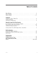
RJP-110S
Remote Jack Pack
Installation
& Setup Guide
Warranty
© Copyright 2007, LG Electronics U.S.A., Inc.
For Customer Support/Service, please call: 1-888-865-3026
www.lgcommercial.com
The exclamation point within an equilateral triangle is intended to alert the user to the presence
of important operating and maintenance (servicing) instructions in the literature accompanying
the appliance.
CAUTION:
TO REDUCE THE RISK OF ELECTRIC SHOCK - - USE ONLY INDOORS
ATTENTION:
RISQUE DE CHOCS ÉLECTRIQUE - - POUR INSTALLATION À L¡¯INTÉRIEUR SEULEMENT
WARNING:
TO PREVENT FIRE OR SHOCK HAZARDS, DO NOT EXPOSE THIS PRODUCT TO RAIN OR MOISTURE.
Apparatus shall not be exposed to dripping or splashing and no objects filled with liquids, such as
vases, shall be placed on the apparatus.
AVERTISSEMENT:
L’appareil ne doit pas être exposé à des égouttements d’eau ou des éclaboussures et de
plus qu’aucun objet rempli de liquide tel que des vases ne doit être placé sur l’appareil.
REGULATORY INFORMATION:
This equipment has been tested and found to comply with the limits for a Class B digital device, pursuant to Part 15 of the FCC Rules. These limits are designed to provide reasonable protection against
harmful interference when the equipment is operated in a residential installation. This equipment generates, uses and can radiate radio frequency energy and, if not installed and used in accordance with
the instruction manual, may cause harmful interference to radio communications. However, there is no
guarantee that interference will not occur in a particular installation. If this equipment does cause
harmful interference to radio or television reception, which can be determined by turning the equipment off and on, the user is encouraged to try to correct the interference by one or more of the following measures:
• Reorient or relocate the receiving antenna.
• Increase the separation between the equipment and receiver.
• Connect the equipment into an outlet on a circuit different from that to which the receiver
is connected.
• Consult the dealer or an experienced radio/TV technician for help.
CAUTION:
Do not attempt to modify this product in any way (except as noted herein) without written authorization from LG Electronics U.S.A., Inc. Unauthorized modification could void the user’s authority to operate this product.
COMPLIANCE:
The responsible party for this product’s compliance is:
LG Electronics U.S.A., Inc., 2000 Millbrook Drive
Lincolnshire, IL 60069, USA • Phone: 1-847-941-8000.
Marketed and Distributed in the United States by LG Electronics U.S.A., Inc.
2000 Millbrook Drive, Lincolnshire, IL 60069
2
© Copyright 2007, LG Electronics U.S.A., Inc.
206-4053
Table of Contents
Safety Warnings . . . . . . . . . . . . . . . . . . . . . . . . . . . . . . . . . . . . . . . . . . . . . . . 2
Table of Contents . . . . . . . . . . . . . . . . . . . . . . . . . . . . . . . . . . . . . . . . . . . . . . 3
Product Overview . . . . . . . . . . . . . . . . . . . . . . . . . . . . . . . . . . . . . . . . . . . . 4 - 5
Installation
Installation on Desk / Cabinet Top . . . . . . . . . . . . . . . . . . . . . . . . . . . . . . . . . . . 6
Installer Connections . . . . . . . . . . . . . . . . . . . . . . . . . . . . . . . . . . . . . . . . . . . . 7
Connections to Display Panel . . . . . . . . . . . . . . . . . . . . . . . . . . . . . . . . . . . . . . 8
Removable 4-page Hole Drilling Template
RJP-110F Remote Jack Pack Hole Drilling Template . . . . . . . . . . . . . . . . . . . . . . . . A
Cabinet/Desk Top Hole Drilling Template . . . . . . . . . . . . . . . . . . . . . . . . . . . . . B-C
Installation/Drilling Instructions . . . . . . . . . . . . . . . . . . . . . . . . . . . . . . . . . . . . D
Accessory Cable: DVI to HDMI Adapter Cable / Strain Relief
..................9
End-User Operation
End-User Multi-Media Connections . . . . . . . . . . . . . . . . . . . . . . . . . . . . . . . . . . . 10
End-User Source Devices & Audio/Video Priorities . . . . . . . . . . . . . . . . . . . . . . . . . 11
Specifications . . . . . . . . . . . . . . . . . . . . . . . . . . . . . . . . . . . . . . . . . . . . . . . . 12
Troubleshooting
Troubleshooting . . . . . . . . . . . . . . . . . . . . . . . . . . . . . . . . . . . . . . . . . . . . . . 13
Troubleshooting Flow Charts . . . . . . . . . . . . . . . . . . . . . . . . . . . . . . . . . . . . . . 14
Quick Setup Reference Guide . . . . . . . . . . . . . . . . . . . . . . . . . . . . . . . . . . . . . 15
Warranty . . . . . . . . . . . . . . . . . . . . . . . . . . . . . . . . . . . . . . . . . . . . . . Back Cover
206-4053
3
Product Overview
The Remote Jack Pack (RJP) contains circuitry to determine the presence of a signal at each input jack.
(Note: Audio In, Audio In L-R and Video In inputs detect the presence of the inserted plug, regardless if a signal is present or not.)
When a source is detected, its priority is compared to the priority of
other sources which may be present. If the newly-connected active
source is of higher priority than the existing source(s), the RJP
directs the TV display panel to that source.
Video and audio are monitored and switched independently.
Power is supplied to the RJP by the TV display panel via the control
signal cable.
PRE
SS
TO
RES
ET
7A
MP
MA
XIM
UM
CUR
REN
T
Two End-User AC Power Outlets
For convenience, two AC power outlets are
provided on the sides. The maximum current
is 7 amps. If this limit is exceeded, the
power is cut off. To restore power, the Reset
button on the backside must be pressed to
reset the circuit breaker.
4
206-4053
Product Overview
CLEANING CAUTION:
Since the end-user jack panel is exposed, use extreme caution when
cleaning. Do not use liquid cleaners on the connections panel. Do
not allow liquids to be spilled, sprayed onto or otherwise come into
contact with the connections panel on the end-user side. Clean with
a slightly damp cloth.
7 AMPS MAXIMUM CURRENT TO AC OUTLETS:
The maximum combined total current that is allowable to the AC
power outlets is 7 Amps. These are protected by a circuit breaker
type re-settable fuse.
Introduction
Conveniently installed right in the room where guests will stay, the LG Remote
Jack Pack, (RJP) multi-media interface is available to end-users to connect audio,
video and computer devices to hear and view on the in-room TV display panel.
The RJP can be set up to interface with the TV display panel to show the image
and/or sound from a portable DVD/CD Player, Camcorder, MP-3 Player, Notebook
computer, or portable Video Game Player. Or, devices with digital video output
such as DVD players. If the end-user does not connect any devices, then the inroom TV display panel will remain on the source selected. When the end-user connects a device, the interface switches the TV display panel to the new source.
Users can recharge laptop or cell phone batteries while watching TV.
The RJP interface is designed to be able to process audio from one source, and
video separately from a different source, if required. (The end-user can work on a
laptop computer while listening to music from an MP-3 player.) However, only
one audio and one video source can be heard/seen at the same time.
The end-user can simply plug the device’s power cord into one of the two convenience AC power outlets provided on the RJP. Then plug in its Audio/Video
cable(s) to the RJP input jack(s) and turn the device on. The RJP completes the
connection between the newly-connected audio and/or video source and the TV
display panel. No end-user menus are involved, all connections are made directly
to the interface.
The RJP continually monitors its source inputs. When a signal is detected, (a
device is plugged into one of the RJP inputs) the interface sends a message to
the TV display panel to switch to the newly-connected source (if the new source
is of higher priority). The interface allows only the higher priority audio and
video to be heard and seen on the TV display panel. The control cable supplies
12 Volt DC power from the TV display panel to operate the interface.
206-4053-A
5
Installation on Desk/Cabinet Top
In-Room TV
RJP-110S
Cable Leads to TV
...... .
.............
. ...
Desktop
As shown above, install on a desk or cabinet in a convenient
location for the end-user to have access to the RJP interface
and so RJP cable bundle connections can be made to the display panel.
Note: The actual appearance of the desk/cabinet etc., may be different than
shown in these drawings.
6
206-4053
Installer Connections
CAUTION: Be sure TV power is turned off before attempting to connect the
RJP-110S remote jack pack to the TV display panel.
AC Power Cord
Connect to a standard
120V 60Hz power outlet.
RJP-110S
Audio/Video Cables
Connect to Left-Right
Audio/composite Video input
jacks on TV display panel.
RGB PC Video Cable
Connect to RGB input on TV
display panel.
.............. .
. ........
Control Cable (8-Pin RJ-45)
w/Yellow Protective Sleeve
Connect to RJP port on TV
display panel.
Digital Video Cable
Connect to digital video input
on TV display panel.
Note: Cable bundle is approximately 11 feet in length.
206-4053
7
Connections to TV Display Panel
After completing connections between the
RJP, the TV display panel and other resources
(if available), be sure the installer menu
items have been updated to enable the RJP.
Installer Menu item 040 Auto Camport needs
to be set to 000 and 093 RJP Available
needs to be set to 001. (See TV installation
guide. The master TV setup can be modified
to include RJP settings for multiple system
installations.)
RS-232C
.....
....
.....
.....
.....
PC IN
RJP
INTERFACE
AUDIO IN
AUDIO IN
VIDEO 2 IN
AC IN
UPDATE
VIDEO 1 IN
RS-232C
M.P.I.
DVI
ANTENNA
CABLE
DVI/PC
AUDIO
IN
CONTROL
NORMAL
(DTV)
FUTURE
USE
DIGTAL AUDIO
OUT (OPTICAL)
.............. .
. ........
RJP-110F
Note: The actual appearance of the TV display
panel connections etc.,
may be different than
shown in this drawing.
8
RJP-110S
206-4053
RJP-110S Remote Jack Pack
Hole Drilling Template
Detach the hole drilling template from the manual by bending up the
staples ends in the center of the manual and removing this sheet.
Bend the staples down again to secure the manual pages.
See the other side of this page for installation details.
Le
ft
Sid
e
nt
Fro
6.10
(Top
do Vie
wn w
on look
Cab in
g
inet
)
"
Rea
r
5.00
"
Rig
ht
Sid
e
Leave adequate
space for
Cable assembly
Template
Positioning
Position the template on the desk
top. Be sure to leave
an adequate amount
of clearance for the
cable assembly
attached to the
backside of the cabinet, based on the
installation requirements/limitations.
Drill Hole Template A
RJP-110S Remote Jack Pack
Hole Drilling Template
Template Size
Before drilling the holes, measure the template to be sure the
holes are the sizes stated. Some printers will change the size
of the page because of their default setup. The print size
selected should be 100% or same size and not ‘fit to page’ or
‘expand to fit’ page etc...
B Drill Hole Template
Rear
Allow 1.5” minimum
clearance for Cable
assembly
for Cabinet or Desk Top Surfaces
Drill Hole Template C
Left
Side
Front
6.26"
(Top View looking
down on Cabinet)
5.26"
Right
Side
RJP-110S Remote Jack Pack
Desk Top Hole Drilling / Mounting Instructions
Hole Drilling Tools Required
-
Drill Bit 1/4”
Drill
Phillips-Head #2 Screw Driver
Center Punch
Masking Tape
Lightweight Hammer
RJP-110S
,,
,,,
3/8" Max. Thread Depth
Parts List
• Drilling Template
• 5-Phillips-Head M4 x 30mm Threaded
Screws (with lock and flat washers) use
for 3/4” thick desktop only.
(4-Required)
Determine
Thickness of
Desk Top
Caution: Screw Length
Note: Length of the screws provided
(M4 x 30mm) is limited to usage for a
desk top thickness of 3/4 inches. For
other desk top thicknesses, determine
screw length allowing for the 3/8”
maximum thread depth of the RJP
screw holes.
Select Screw Length
Based on Limitations
of Desk Top Thickness
and RJP Thread Depth
Drilling Setup and Procedure
1. Position hole drilling template on cabinet surface
or desk top.
2. Tape the template into position using the masking
tape.
3. Using the light-weight hammer and center punch,
make four hole drilling indents into the mounting
surface and remove the template.
Note: Be sure the hole drilling indents are sufficiently deep enough to center and guide the drill
bit. Or, use a smaller size drill bit just to start the
hole recess.
4. Drill the four holes using the 1/4” drill bit.
D Drill Hole Template
Desk Top
M4 Threaded Screw
5. Clean up and remove any residue from drilling the
holes.
6. Install the RJP on the desk top using the threaded screws and lock washers provided*.
7. Hand tighten all screws securely.
8. Make all connections from the RJP, to the TV display panel and any other in-room resources etc.
9. Test RJP operation.
* The maximum depth the M4 screws can be threaded into the RJP bosses is 3/8”. Use spacers if necessary to compensate for excessive screw length.
Maximum screw length is 3/8” plus depth of cabinet or desk top.
206-4053-A
Accessory Cable: DVI to HDMI Adapter Cable
/ Strain Relief
Special Connections
Note: Optional DVI to
HDMI Adapter Cable
Male
Connector
Female
Connector
For TVs equipped with
HDMI, this adapter cable
will be required to connect
the RJP for digital
video/audio.
RS-232C
.....
....
.....
.....
.....
PC IN
AUDIO IN
UPDATE
VIDEO 1 IN
RS-232C
CONTROL
DIGTAL AUDIO
OUT (OPTICAL)
NORMAL
(DTV)
AUDIO IN
M.P.I.
HDMI/DVI
IN
ANTENNA
CABLE
DVI/PC
AUDIO
IN
RJP
INTERFACE
AC IN
FUTURE
USE
VIDEO 2 IN
Strain Relief for Accessory
HDMI Cable
The weight of the DVI
adapter connection/cable
bundle may put a strain on
the HDMI connection, causing it to become disconnected from the TV. Relieve the
weight by attaching a cable
tie in the position shown.
Note: The actual appearance of
the TV connections panel may be
different than shown in this
drawing.
206-4053
9
End-User Multi-Media Interface Connections
The end-user simply plugs a device such as a laptop computer with the appropriate cables into the RJP
connection panel. The Remote Jack Pack senses the new source connection and switches the TV to the
newly-connected source. The device’s sound and image are then presented on the in-room TV display
panel. The TV display panel adjusts automatically to the computer output format. When the laptop is
disconnected, the interface directs the TV to revert back to the previous source for video and audio.
The end-user has several audio/video connection options available for connecting external devices. The
guest/user can connect a portable DVD Player, CD Player, Camcorder, MP-3 Player, Notebook Computer,
Portable Video Game Player, etc. For added convenience, two AC power outlets are also available on
the sides of the interface to provide power for these external devices and/or recharge laptop or cell
phone batteries. (The maximum combined current allowed for the AC power outlets is 7 Amps.)
An end-user could connect and hear audio from one device and connect and view video from a different device. The RJP offers two different stereo audio input jacks to accommodate various end-user
devices. However, only the higher priority audio source will be selected and heard. Similarly, multiple
video inputs are available, but only the higher priority video source will be selected and displayed.
(Note: Audio In, Audio In L-R and Video In inputs detect the presence
of an inserted plug, regardless if a signal is present or not.)
PRE
SS
TO
RES
ET
7A
MP
MA
XIM
UM
CUR
REN
DIGITAL VIDEO IN
PC VIDEO IN
VIDEO IN
AUDIO IN
L
R
AUDIO IN
T
Circuit Breaker for AC Outlets
If the 7 Amp maximum current is
exceeded, the circuit breaker
is tripped and AC power is
turned off. Remove all AC
power cords and then push
Reset button in to restore AC power.
3.5 mm Stereo Audio Input Jack
Connection for MP-3 player or PC audio.
L-R Audio/Video Input Jacks
Connection for Left-Right Audio/composite Video sources.
PC Video (RGB) Input Port
Connection for PC Video.
Digital Video Input Port
Connection for digital video sources. (portable DVD)
10
206-4053
End-User Connectable External Source Devices
Examples of devices a guest/end-user
can connect are shown to the right.
There are two AC power outlets available on the jack pack for added convenience.
The End-User Can Connect:
• PC Laptop/Notebook Computers
• Portable Video Game Players
• Portable DVD/CD Players
• Camcorders
• Digital Cameras
• MP-3 Audio Players
End-User Audio/Video Input
Priorities
Note: The highest priority is listed first.
Audio Inputs/Sources
1st. 3.5 mm Stereo Audio Jack
2nd. Left - Right Audio Jacks
3rd. Digital Video Audio
4th. TV Display Panel Tuner Audio (Audio Default)
Video Inputs
1st. Digital Video
2nd. PC Video
3rd. Video Composite Jack
4th. TV Display Panel Tuner Video (Video Default)
206-4053-A
11
Specifications
Application
Makes available to the hotel’s guests, a multi-media interface to the in-room TV display
panel and in-room audio source (if available). Input jacks are provided for external
portable devices such as DVD/CD Players, Laptop Computers, Camcorders, etc.
Dimensions
Height
Width
Depth
Weight
End-User Device Inputs
AC Outlets x 2
Audio In
Audio In L-R
Video In
PC Video In
Digital Video In
3.68 Inches
7.47 Inches
7.47 Inches
5.25 Pounds
( 9.3 cm)
(19.0 cm)
(19.0 cm)
(2.381359 kgrms)
AC 120V 60Hz (Maximum 7 Amps.
total combined current allowed for AC outlets)
3.5 mm Stereo Audio Jack
Left - Right Audio Jacks
(Nom In: 250mV RMS @ 22K ohms)
Overload In: 1.6V RMS Max
Composite Video Jack
1 Vpp, 75 ohms
15-pin RGB PC Monitor Connector
Digital Video Connector
Regulatory
UL, FCC
Environmental Parameters
Operating Temperature
Storage Temperature
Cooling
Humidity
Class B, Digital Video Device
0° to 40° Degrees Celsius (32° to 104° Degrees Fahrenheit)
-20° to 85° Degrees Celsius (-4° to 185° Degrees Fahrenheit)
Free Air Convection
10% to 90% Non-condensing
Supplied Accessories List
(Attached Cable Assembly) Note: All cables within cable bundle are 12 feet in length.
• Digital Video Cable
• PC Video RGB Cable
• Control Cable (8-Pin RJ-45)
• 1-Set Left-Right Audio/Video Cables
(Attached Cord)
• AC Power Cord, 120V 60Hz
(Misc. Hardware)
• 1 Black Cable Tie (DVI to HDMI Adapter Cable see page 9.)
• 5 Phillips-Head Machine Screws (4-M4 x 30mm required for
3/4” desk top)
• 5 Serrated Lock Washers (4-Required)
(Separate Cable)
• DVI (F) to HDMI (M) Adapter Cable (Optional connection)
Note: Design and specifications subject to change without prior notice.
12
206-4053
Troubleshooting
Equipment Setup Analysis Notes
• Make sure all connectors and connections are tight and secure on user device, RJP-110S and TV.
• Check to assure user device, RJP-110S and TV are all powered up and working properly and that the TV
Installer menu items are set correctly.
• Audio and Video can be from different sources. Default is TV tuner Audio and Video, if no other
audio/video source is connected.
• Audio source must be viable. The audio output from the customer’s device must be present when connected to be heard at the TV.
• RJP AC circuit breaker maximum is 7 Amps. If the 7 Amp current limit is exceeded, the breaker will trip;
unplug all accessory devices from RJP AC outlets and press RESET on back of unit.
Test Procedures
• Test and connect only one user device to determine if RJP is providing audio/video to TV.
• Test user device on another RJP (perhaps located in a different room) to determine if user device is compatible with RJP.
• On LCD or Plasma TV, Installer menu items:
040 Auto Camport needs to be disabled by setting it to 000.
093 RJP Available needs to be set to 001 to enable RJP mode.
Following are some possible solutions to problems:
Problem
Possible Cause(s) Check RJP, User Device and In-Room TV
No Power
• Power not connected?
• Circuit breaker on RJP tripped?
(Unplug all accessory devices from RJP AC outlets, press RESET on back of unit.)
No Audio
•
•
•
•
•
•
•
•
Have all audio connections been made?
Audio output available?
Volume level turned up?
Sound muted?
TV setup correct for RJP? (Installer menu item 040 is set to 000 and 093 set to 001.)
Try another RJP.
Priority level? (Disconnect other devices.)
Connections made after 040 and 093 menu items set.
(Make connections before adjusting menu items 040 and 093.)
No Video
•
•
•
•
Video output available?
All video cables connected?
TV setup correct for RJP? (Installer menu item 040 is set to 000 and 093 set to 001.)
Priority level? (Disconnect other devices.)
Poor Video
• Check connections. (Video pass-through no user action possible.)
206-4053
13
Troubleshooting Flow Charts
No Audio (or
not desired
Audio)
No
Power
Power
Failure?
Yes
Restore
Power
No
Connect
Power
Cord
No
RJP
Is power cord
connected
?
RJP
Has Circuit
Breaker
Tripped
?
No
RJP
Is Audio
connected
?
Yes
No
Remove AC
load, press
RESET
Connect
Audio
Cables
RJP
Has Circuit
Breaker
Tripped
?
No
RJP
Is Video
connected
?
Yes
Remove AC
load, press
RESET
RJP
Are other
audio devices
connected
?
Yes
Disconnect
other
Audio devices
No
No
Connect
Power
Cord
TV
Is TV
turned
On
?
No
Yes
No
Turn
Power
On
Yes
TV
Are
Speakers
turned Off
?
Turn
TV On
Are
Installer menu
items set up?
Yes
Turn
Speakers
On
No
User
Device
Is power cord
connected
?
Connect
Video
Cables
RJP
Are other
Video devices
connected
?
Yes
Disconnect
other
Video devices
No
Turn
TV On
No
Yes
TV
Is TV power
turned on
?
No
Remove AC
load, press
RESET
Yes
No
TV
Is power cord
connected
?
Yes
Yes
Yes
RJP
Has Circuit
Breaker
Tripped
?
No Video (or
not desired
Video)
No
Connect
Power
Cord
Yes
TV
Is sound
Muted
or set too
low
?
Yes
Press
Volume
Up
TV
Is TV
turned
On
?
Yes
Are
Installer menu
items set up?
User
Device
Is correct
Video output
selected
?
No
Select
correct Video
output
PC
External
Port
Yes
No
User
Device
Is device
turned On
?
Yes
No
Turn
Power
On
User
Device
Is Audio
connected
?
User
Device
Is Video
connected
?
No
No
Connect
Connect
Yes
Yes
User
Device
Audio
available &
turned up
?
14
No
Turn
Volume
Up
206-4053
Quick Setup Reference Guide
Installer RJP-110S Quick Setup
Reference Guide
Following are the tasks associated
with installing and setting up an RJP
System.
1. Install RJP on cabinet.
2. Make all hard wire connections to
RJP, TV and any other in-room
resources.
3. Plug all system components into
power sources.
4. Adjust TV installer menu items 040
and 093 to enable RJP capability.
(See TV installation guide for complete instructions on new TV
installations. The master TV setup
can be modified to include RJP
settings for multiple system installations.)
5. Test the system with user-type
devices to assure TV sound/picture
are as desired.
6. Provide user information in room.
(As applicable to your entertainment system.)
• RJP-110S Series Tent Card.
(Or comparable equivalent from
Lodge)
• RJP-110S Series Quick Reference
Guide. (Or comparable equivalent
from Lodge)
Typical TV Display Panel
Installer Menu
In-Room TV
)
into V.
ide gged on T
rs
lu ort
the ter p rep
e o ompu stockuter.
eo
e p
c
Vid
PC h th om
C,
nd atc C c
pP
e a nd w nal P
to
n
o
c
ho a
Lap
Ja cell p layer r pers
yer,
te
p ou
r
Pla ne.
mo e you a CD use y
P-3 ll pho
e
M
v
R
to nd
ha
er, r ce
to sten rk a
0F
cord you
11 ld be you li etwo
Cam like
n
Pu
yer, es
RJ ge wo while ment
3
MP r
Pla evic
ye
usa ing ain
CD t d
Pla
of rg tert
D/ en
l
le cha en
DV m
ita
le rtain
mp ts re otel
Dig era
b
a
a
x
te
h
e
rt
Cam
n e utl e
po l en
• A AC o to th
ur ona
rder
o
co
y
ers
ct
the listen
Cam
ne er p
Or,
con r oth
D
can r o
DV r
ye
ou ye
Pla
• Y e Pla
m
e
Ga
am
ck
(Se
a
kP
RJP-110S
Cable Leads to TV
...... .
.............
. ...
Desktop
Item
040
093
Description
Auto Camport
RJP Available
Set
000
001
G
Mac
hine
®
PC
3.
2.
1.
RS-232C
.....
....
.....
.....
.....
PC IN
RJP
INTERFACE
AUDIO IN
VIDEO 1 IN
AUDIO IN
VIDEO 2 IN
AC IN
UPDATE
RS-232C
M.P.I.
DVI
ANTENNA
CABLE
DVI/PC
AUDIO
IN
CONTROL
NORMAL
(DTV)
FUTURE
USE
e
rfac
Inte uide
edia e G
i-M renc
Mult k Refe
Quic
DIGTAL AUDIO
OUT (OPTICAL)
.............. .
. ........
RJP-110F
el.
s hot
ilable
RJP-110S
y not
ve ma le.
wn abo availab
s sho ces are
option our
tion what res
connec firm
media to con
multi- hotel
All the with the
Note: check
Please
PC
e
Gam
hine
Mac
DVD
er
Play
er
cord
Cam
tal
Digi
era
Cam
Standard
120 Volt
60 Hz AC
Power
Outlet
206-4053
MP3
er
Play
at thi
be ava
ack
video
dio,
ck P rface
nal au l.
te Ja Inte
persolay pane
emo edia
ect
S R ulti-M ed to connm TV/disp
r,
M
-110
roo
Playe terprovid e inD/CD her en
RJP Guest
ck is on th
l
ble DVand ot tch TV.
te
ck Pa d view
rta
o
r
Ja
po
H
a
Playe and wa
mote ar an
ect
Re to he
or
Game etc.
conn
e LG
kers
can , Video laptop
• Th devices
e ma tlets
you
e,
PC
left, ptop PC ll phon
, coffe r ou
and
La
the
ce
irons AC powe
ing
r
n on Player, e your
ps.
-3
cloth e fou
show
arg
ers, es to th is 10 Am
• As er, MP es -- ch
ord
ir dry
t ha ic devicr outlets
Camc ent devic
ctr
nnec
t co nt ele all fou
tlets. erface.
tainm
no
ou
int
Do
AC
curre load for
four -media ent
ce
ION: highthe
lti
terfa
CAUT similar maximum
fer
rk
r
ia In one of the mu a dif u wo
othe ed. The
Med rd into tput to eo from while yo yer
pla
ultiprovid
e M power co ideo ou view vid player MP-3 typically
ur
/v
e th
-3
d
more nnecm yo
to Us vice’s audio e an ur MP
How g your de device’s one devic n to yo sound froreen. Or, able co
te
e
sc
• Plu ect th dio from can lis TV plays e TV’s for avail
u
e
nn
th
m
au
yo
Co
sid
on
r
•
to
roo age
othe
ten
ample e in• Lis For ex PC. Th p PC’s im e. (See
e.
p
devic ur lapto ur lapto me devic
yo
sa
on yo plays m the
dis
and /video fro
audio
.)
tions
15
LG RJP-110S Warranty
Remote Jack Pack Welcome to the LG family! We believe that you will be pleased with your new LG product.
Please read this warranty carefully, it is a “LIMITED WARRANTY” as defined under Federal Law.
This warranty gives you specific legal rights, and you may also have other rights that vary
from state-to-state within the U.S.A.
LG’S RESPONSIBILITY
Service Labor
Replacement
Warranty Service
Not Covered
During a period of one year from effective warranty date, LG will replace a defective unit, as
determined by the LG service center, as a result of manufacturing defects.
New or remanufactured replacements for factory-defective units will be supplied by an LG
authorized service center for one year from effective warranty date. Such replacement unit is
warranted for the remaining portion of the original warranty period.
Warranty service is provided.
Call 1-888-865-3026 for further information.
This warranty covers manufacturing defects and does not cover installation, adjustment of
customer controls, installation or repair of antenna systems, cable converters or cable company-supplied equipment; it also does not cover damage due to misuse, abuse, negligence, acts
of God or other causes beyond the control of LG. Any alteration of the product after manufacture voids this warranty in its entirety.
THIS WARRANTY IS IN LIEU OF ANY OTHER WARRANTY, EXPRESS OR IMPLIED, INCLUDING
WITHOUT LIMITATION, ANY WARRANTY OF MERCHANTABILITY OR FITNESS FOR A PARTICULAR PURPOSE, AND LG SHALL NOT BE LIABLE FOR ANY CONSEQUENTIAL, INDIRECT, OR
INCIDENTAL DAMAGES OF ANY KIND, INCLUDING LOST REVENUES OR PROFITS IN CONNECTION WITH THIS PRODUCT. SOME STATES DO NOT ALLOW LIMITATIONS ON HOW LONG AN
IMPLIED WARRANTY LASTS OR THE EXCLUSION OR LIMITATION OF INCIDENTAL OR CONSEQUENTIAL DAMAGES, SO THE ABOVE LIMITATIONS OR EXCLUSIONS MAY NOT APPLY TO
YOU.
OWNER’S RESPONSIBILITY
Effective
Warranty Date
Installation
Guide
Antenna
Audio Output
Warranty Service
Warranty begins on the date of installation of the RJP-110S Multi-Media Interface.
For your convenience, keep the dealer’s dated bill of sale or delivery ticket as evidence
of the purchase date.
Read the Installation and Setup Guide carefully so that you will understand the functions of
the RJP-110S and how to make adjustments.
Reception problems caused by inadequate antenna or faulty antenna connections are the
owner’s responsibility.
Audio problems caused by inadequate audio devices or audio material with sound level lapses
are not within the control of LG and therefore are the owner’s responsibility.
For warranty service information, call 1-888-865-3026.
- A replacement unit that is LG’s responsibility (see above) will be provided without charge.
Other service is at the owner’s expense.
- If you have any problem in obtaining satisfactory warranty service, call 1-888-865-3026.
- You must provide the model number, serial number and date of purchase or date of original
installation.
- Before you ask for warranty service, reread this guide. You might avoid a service call.
For Customer Support/Service please call: 1-888-865-3026
www.lgcommercial.com
LG Electronics U.S.A., Inc.
2000 Millbrook Drive, Lincolnshire, IL 60069
206-4053
Issue-A