1
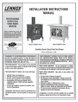
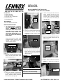
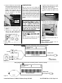
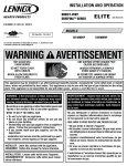
INSTALLATION
INSTRUCTIONS
BK-CI BLOWER KIT (CAT. NO. H0767)
FOR MODELS – CI1500 AND CI2500 SERIES
6.
KIT CONTENTS:
1 ea. Blower Assembly
1 ea. Rheostat Assembly
1 ea. Fan Disc with 1 ea. White Wire
5 ea. Screws, #8 x ½”
1 ea. Instruction Sheet
Remove 2
bolts on
each side of
rear shroud.
Shroud
TOOLS REQUIRED:
1/4” & 7/16” Nut Drivers or Sockets
INSTALLATION INSTRUCTIONS:
1. The following instructions, 1 through 11
are for units WITHOUT an Optional Full
Function Flame Modulating Remote
Control System, H0301 or H0302. If either
of these kits have been purchased, follow
instructions on Page 2 instead – See
INSTALLATION INSTRUCTIONS for units
WITH a Full Function Flame Modulating
Remote Control.
Locate the long black wire from the
blower assembly and pass the wire
through the hole in the rear shroud. Stow
the wires into the existing wire holders
on the inside of the rear shroud (see
Figure 6a & 6b).
Pass wire
through
hole
Stow wires
into holders
Figure 3
4.
Using a ¼” nut driver install the fan disc
with white wire onto the stove back
(install with 2 existing screws as shown
in Figure 4).
Using a 1/4” nut driver or socket, install
the Blower Assembly, using the 3 screws
provided, to the bottom of the rear
shroud as shown in Figure 1.
Install disc
with wire
Long black
wire from
blower
Figure 6a
Figure 6b
7. Connect the remaining black wire from the
blower to the bottom terminal on disc as
shown in Figure 7.
Install blower using 3
screws provided
Connect the
remaining wire
from the blower
to the fan disc
Figure 4
5.
Figure 1
2. Disconnect the 2 black wires from the on/off
switch at the valve (from terminals TP/TH
and TH). See Figures 2 & 10.
Pass the white wire from the fan disc
through the hole in the rear shroud and
connect it to the white rheostat wire (as
shown in Figure 5).
.
White wire from disc
Connect white wires
Figure 7
8. Slide the sleeves on the wires to cover the
connectors on the fan disc as shown in
Figure 8.
Hole
Disconnect 2
black wires
Shroud
Figure 5
Figure 2
3. Using a 7/16” nut driver or socket, remove
the 4 bolts on the rear shroud as shown in
Figure 3. Carefully lift off the shroud and
turn it to the side (see Figure 4).
Slide the sleeves
on wires to cover
connectors
Important Note: Ensure that the wires and
connectors are completely through the hole
and contained in the rheostat housing.
Lennox Hearth Products; 1110 West Taft Avenue; Orange, CA 92865
Figure 8
Part #775146M Rev. A, 12/03, Page 1 of 2
9. Connect the black wire from the blower
(step 6) to the black rheostat wire. Using a
¼” nut driver, install the rheostat housing
onto the rear shroud using the 2 screws
provided. Ensure that the wires and
connectors are completely through the
hole and contained in the rheostat
housing. See Figure 9.
Secure rheostat
housing to
shroud using 2
screws provided
Figure 9
10. Reinstall rear shroud (reverse step 3 on
page 1).
11. Reconnect the 2 black on/off switch
wires to the valve (TP/TH and TH
terminals). See Figure 1 and Figure 10.
Reconnect burner switch wires.
BLOWER OPERATION:
When the stove heats up, the blower will
automatically turn on at the speed determined
by the rheostat. To adjust the blower speed,
dial the rheostat to the desired speed setting.
Turn the knob clockwise just past the click
(the first ON position) for the highest speed
setting. Turning the knob further clockwise
will provide slower blower speeds. Note: If the
rheostat is not turned “on”, the blower will not
operate.
WARNING: The power cord MUST
BE PLUGGED DIRECTLY INTO A
PROPERLY GROUNDED, 120 VOLT,
60 HZ, 3-PRONG RECEPTACLE
electrical outlet. Do not cut or
remove the grounding prong from
this plug. It must be routed to avoid
contact. Do not route power cord
under or in front of appliance.
1. Install the blower, disconnect the on/off
switch wires and remove the rear shroud
(Follow steps 1, 2 & 3 on page 1).
2. Connect the 2 black wires together from
the blower assembly. See Figure 11 and
14.
Connect the 2 black wires
together from blower.
Blower
Figure 11
3. Stow wires into existing wire holders on
the inside of rear shroud. See Figure 12.
Wire Holders
INSTALLATION INSTRUCTIONS:
(for units WITH a Full function flame
modulating Remote Control System, H0301
or H0302)
Note: The rheostat assembly, fan disc (with
wire) and the #8 screws will not be used.
Figure 12
4. Reinstall rear shroud (reverse step 3 on
page 1).
BLOWER OPERATION:
Follow instructions provided with the
modulating remote control kit.
Figure 10
Wiring Diagram (WITHOUT full function modulating remote control kit installed)
BLOWER MOUNTING
BRACKET
BLACK
F
FAN DISC
F
WHITE
POWER CORD
RHEOSTAT
BLOWER ASSEMBLY
M
F
WHITE
F
M
BLACK
NOTE:
M = MALE CONNECTOR
F = FEMALE CONNECTOR
BLACK
Figure 13
Wiring Diagram (WITH full function modulating remote control kit installed)
BLOWER MOUNTING
BRACKET
BLACK
POWER CORD
F
BLOWER ASSEMBLY
M
BLACK
Figure 14
Lennox Hearth Products; 1110 West Taft Avenue; Orange, CA 92865
Part #775146M Rev. A, 12/03, Page 2 of 2
![ifCalibSTD取扱説明書[PDF:549.2KB]](http://vs1.manualzilla.com/store/data/006720962_2-f6f093a08a8e1adf50f2443be8c61b6f-150x150.png)