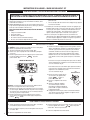
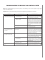
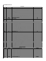
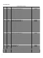
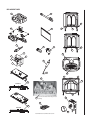
1
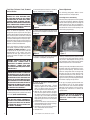
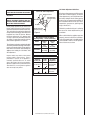
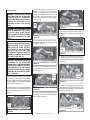
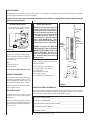
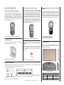
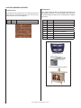
HOMEOWNERS CARE AND
OPERATION INSTRUCTIONS
FREESTANDING
VENTED GAS
FIRED ROOM
HEATERS
Model CI1500DVF Series
Report No. 116-S-08-5
Model CI2500DVF Series
Serefina Series Direct Vent Gas Stoves
P/N 775,148M Rev. B, 11/04
WARNING: IF THE INFORMATION IN THIS MANUAL
IS NOT FOLLOWED EXACTLY, A FIRE OR EXPLOSION MAY RESULT CAUSING PROPERTY DAMAGE,
PERSONAL INJURY OR LOSS OF LIFE.
FOR YOUR SAFETY: Do not store or use gasoline
or other flammable vapors or liquids in the vicinity
of this or any other appliance.
FOR YOUR SAFETY: What to do if you smell gas:
•
•
•
•
DO NOT light any appliance.
DO NOT touch any electrical switches.
Do not use any phone in your building.
Immediately call your gas supplier from a neighbor’s
phone. Follow your gas suppliers instructions.
• If your gas supplier cannot be reached, call
the fire department.
Installation and service must be performed by
a qualified installer, service agency or the gas
supplier.
AVERTISSEMENT: ASSUREZ-VOUS DE BIEN SUIVRE
LES INSTRUCTIONS DONNÉ DANS CETTE NOTICE
POUR RÉDUIRE AU MINIMUM LE RISQUE D’INCENDIE
OU POUR ÉVITER TOUT DOMMAGE MATÉRIEL, TOUTE
BLESSURE OU LA MORT.
POUR VOTRE SÉCURITÉ: Ne pas entreposer ni utiliser
d’essence ni d’autre vapeurs ou liquides inflammables dans
le voisinage de cet appareil ou de tout autre appareil.
POUR VOTRE SÉCURITÉ: Que faire si vous sentez une
odeur de gaz:
• Ne pas tenter d’allumer d’appareil.
• Ne touchez à aucun interrupteur. Ne pas vous servir
des téléphones se trouvant dans le batiment où vous
vous trouvez.
• Evacuez la piéce, le bâtiment ou la zone.
• Appelez immédiatement votre fournisseur de gaz
depuis un voisin. Suivez les instructions du fournisseur.
• Si vous ne pouvez rejoindre le fournisseur de gaz,
appelez le service dos incendies.
L’installation et service doit être exécuté par un qualifié
installeur, agence de service ou le fournisseur de gaz.
CONGRATULATIONS ON THE PURCHASE OF YOUR NEW GAS APPLIANCE MANUFACTURED BY LENNOX HEARTH PRODUCTS.
When you purchased your new gas fired heater, you joined the ranks of thousands of
concerned individuals whose answer to their home heating needs reflects their concern for
aesthetics, efficiency and our environment. We extend our continued support to help you
achieve the maximum benefit and enjoyment available from your new gas fired heater. It
is our goal at Lennox Hearth Products to provide you, our valued customer, with an appliance that will ensure you years of trouble free warmth and pleasure.
Thank you for selecting a Lennox Hearth Products gas fired heater as the answer to
your home heating needs.
Sincerely,
All of us at Lennox Hearth Products
TABLE OF CONTENTS
Introduction ......................................page
2
General Information ..........................page
2
Operation/Care of Your Appliance .....page
3
Control Compartment Access ...........page
3
Variable Flame Adjustment................page
4
Burn-In Period ..................................page
4
Maintenance......................................page
4
Glass Cleaning ..................................page
4
Maintenance Schedule ......................page
5
Front Glass Enclosure Panel,
Removal and Installation .................page
6
Burner Adjustments ..........................page
6
Flame Appearance and Sooting .........page
6
Adjustment........................................page
7
Log Placement ..................................page
8
Rockwool Placement.........................page
9
Millivolt Appliance Checkout .............page
9
Wiring Diagrams ...............................page 10
Warranty Information ........................page 10
These millivolt appliances are designed to
operate on either natural or propane gas. A
millivolt gas control valve with piezo ignition
system provides safe, efficient operation.
External electrical power is required to operate
the optional electrically powered components
if installed.
These appliances comply with National
Safety Standards and are tested and listed
by OMNI-Test Laboratories Inc.; Beaverton,
Oregon (Report No. 116-S-08-05) to ANSI
Z21.88-2002 (in Canada, CSA-2.33-2002),
and CAN/CGA-2.17-M91 in both USA and
Canada, as vented gas heaters.
Installation must conform to local codes. In
the absence of local codes, installation must
comply with the current National Fuel Gas Code,
ANSI Z223.1 (NFPA 54). (In Canada, the current
CAN/CGA B149 installation code.) Electrical
wiring must comply with local codes. In the
absence of local codes, installation must be in
accordance with the National Electrical Code,
NFPA 70 - (latest edition). (In Canada, the current
CSA C22.1 Canadian Electric Code.).
Accessory Components ....................page 11
Lighting Instructions – Millivolt ........page 13
Troubleshooting Guide – Millivolt .....page 15
Replacement Parts List .....................page 16
DO NOT ATTEMPT TO ALTER OR MODIFY
THE CONSTRUCTION OF THE APPLIANCE OR ITS COMPONENTS.
ANY MODIFICATION OR ALTERATION MAY VOID THE WARRANTY,
CERTIFICATION AND LISTINGS OF THIS
UNIT.
INTRODUCTION
The Stove models covered in this manual are
Direct-Vent sealed combustion vented gas
stove heaters designed for residential application. Direct-Vent appliances operate with the
combustion chamber isolated from the inside
atmosphere. All air for combustion is brought in
from the outside and exhaust gases are vented
through the same direct vent, vent system.
WARNING: IMPROPER INSTALLATION,
ADJUSTMENT, ALTERATION, SERVICE
OR MAINTENANCE CAN CAUSE INJURY
OR PROPERTY DAMAGE. REFER TO
THIS MANUAL. FOR ASSISTANCE OR
ADDITIONAL INFORMATION CONSULT
A QUALIFIED INSTALLER, SERVICE
AGENCY OR THE GAS SUPPLIER.
GENERAL INFORMATION
Note: Installation and repair should be performed
by a qualified service person. The appliance
should be inspected annually by a qualified
professional service technician. More frequent
inspections and cleanings may be required due to
excessive lint from carpeting, bedding material,
etc. It is imperative that the control compartment,
burners and circulating air passage ways of the
appliance be kept clean.
S'assurer que le brùleur et le compartiment des
commandes sont propres. Voir les instructions
d'installation et d'utilisation qui accompagnent
l'appareil.
Provide adequate clearances around air openings
and adequate accessibility clearance for service
and proper operation.
Never obstruct the front openings of the
appliance.
Due to high temperatures the appliance should
be located out of traffic and away from furniture
and draperies. Locate furniture and window
coverings accordingly. The recommended
clearance zone from the front of the appliance to combustibles is 36 inches (914 mm).
Maintain all other clearances as outlined in the
Installation Manual.
WARNING: THESE STOVES ARE VENTED
HEATERS. DO NOT BURN WOOD OR OTHER
MATERIAL IN THESE APPLIANCES.
These appliances are designed to operate on
natural or propane gas only.
Input of millivolt models is variable. These rates
are shown in the following table:
Input (BTU/HR) Manually-Modulated Gas
Valves (millivolt models)
Models
Nat. Gas
Propane
CI1500DVF
17,500 to
28,000
20,500 to
27,000
CI2500DVF
25,500 to
38,500
26,500 to
34,500
Table 1
Table 2 shows the units' gas orifice size for
the elevations indicated.
Burner Orifice Sizes
Model
No.
Nat.
Gas
Prop.
Gas
Elevation
Feet
(meters)
CI1500DVF .104"
.061"
0-4500
(0-1372)
.068"
0-4500
(0-1372)
CI2500DVF
Table 2
2
NOTE: DIAGRAMS & ILLUSTRATIONS NOT TO SCALE.
.121"
4.5" WC
(1.12 kPa)
10.5" WC
(2.61 kPa)
Propane
11.0" WC
(2.73 kPa)
13.0" WC
(3.23 kPa)
Table 3
Manifold Gas Supply Pressure
(millivolt models)
Fuel #
Low
High
Natural
Gas
(Lo) 1.6" WC
(.40 kPa)
(Hi) 3.5" WC
(.87 kPa)
Propane
(Lo) 6.3" WC
(1.57 kPa)
(Hi) 10.0" WC
(2.49 kPa)
WARNING: FAILURE TO COMPLY WITH THE
INSTALLATION AND OPERATING INSTRUCTIONS PROVIDED IN THIS DOCUMENT WILL
RESULT IN AN IMPROPERLY INSTALLED
AND OPERATING APPLIANCE, VOIDING ITS
WARRANTY. ANY CHANGE TO THIS APPLIANCE AND/OR ITS OPERATING CONTROLS
IS DANGEROUS. IMPROPER INSTALLATION
OR USE OF THIS APPLIANCE CAN CAUSE
SERIOUS INJURY OR DEATH FROM FIRE,
BURNS, EXPLOSION OR CARBON MONOXIDE POISONING.
Table 4
Do not use these appliances if any part has
been under water. Immediately call a qualified,
professional service technician to inspect
the appliance and to replace any parts of the
control system and any gas controls which
have been under water.
Ne pas se servir de cet appareil s'il a été
plongé dans l'eau, complètement ou en
partie. Appeler un technicien qualifié pour
inspecter l'appareil et remplacer toute partie
du système de contrôle et toute commande
qui ont été plongés dans l'leau.
Test gage connections are provided on
the front of the millivolt gas control valve
(identified IN for the inlet and OUT for the
manifold side).
WARNING: DO NOT PLACE CLOTHING OR
OTHER FLAMMABLE MATERIALS ON OR
NEAR THIS APPLIANCE.
AVERTISSEMENT: SURVEILLER LES
ENFANTS. GARDER LES VÊTEMENTS,
LES MEUBLES, L'ESSENCE OU AUTRES
LIQUIDES À VAPEUR INFLAMMABLES
LOIN DE L'APPAREIL.
Burner On/Off Switch
Burner
On /Off
Switch
Top View
Front
Figure 1
Control Compartment Access
The gas controls can be found behind the lower
access door. To access, pull the door open
(see Figure 2).
Lower Access Door
Pull open lower door to access Valve Contols
Lower Access
Door
Figure 2
Millivolt appliances will be fitted with the gas
control valve shown in Figure 3. Familiarize
yourself with the gas control valve that your
appliance uses.
SIT Millivolt Gas Valve Controls
OPERATION AND CARE OF YOUR
APPLIANCE
HI / LO Knob
Variable Flame Height Adjustment
Inlet
Pressure
Port
Manifold Pressure Port
Appliance operation may be controlled through
a remotely located optional wall thermostat or
remote control.
NOTE: DIAGRAMS & ILLUSTRATIONS NOT TO SCALE.
it
If your millivolt appliance is equipped with an
optional wall thermostat kit or remote control
kit and the pilot is lit, the appliance main burner
may be turned on and off with the wall thermostat
or remote control.
PIL O T
These appliances must not be connected to a
chimney or flue serving a separate solid fuel
burning appliance.
OF
LO W
TH
In lieu of remote or remote wall thermostat
operation, the appliance must be operated
directly through the on/off rocker switch located
on the upper right side of the rear shield. See
Figure 1.
TP
These appliances and their individual shut-off
valves must be disconnected from the gas
supply piping system during any pressure
testing of that system at pressures in excess
of 1/2 psig (3.5 kPa).
TPTH
These appliances must be isolated from the
gas supply piping system (by closing their
individual manual shut-off valve) during any
pressure testing of the gas supply piping
system at test pressures equal to or less
than 1/2 psig (3.5 kPa).
WARNING: CHILDREN AND ADULTS
SHOULD BE ALERTED TO THE HAZARDS
OF HIGH SURFACE TEMPERATURES. USE
CAUTION AROUND THE APPLIANCE TO
AVOID BURNS OR CLOTHING IGNITION.
YOUNG CHILDREN SHOULD BE CAREFULLY
SUPERVISED WHEN THEY ARE IN THE SAME
ROOM AS THE APPLIANCE.
Gas Controls
OT
Natural Gas
F
P IL
Maximum
ON
Minimum
Remember, Millivolt appliances have a continuous burning pilot flame. Exercise caution when
using products with combustible vapors.
HI
Fuel #
Always keep the appliance area clear and free
from combustible materials, gasoline and other
flammable liquids.
OUT
Inlet Gas Supply Pressure
(all models)
CARBON MONOXIDE POISONING: EARLY
SIGNS OF CARBON MONOXIDE POISONING
ARE SIMILAR TO THE FLU WITH HEADACHES,
DIZZINESS AND/OR NAUSEA. IF YOU HAVE
THESE SIGNS, OBTAIN FRESH AIR IMMEDIATELY. TURN OFF THE GAS SUPPLY TO THE
APPLIANCE AND HAVE IT SERVICED BY A
QUALIFIED PROFESSIONAL, AS IT MAY NOT
BE OPERATING CORRECTLY.
IN
Tables 3 and 4 show the units' gas pressure
requirements
Main Gas
Control Knob
Figure 3
Piezo Igniter
3
Lighting Millivolt Appliances
To light millivolt appliances refer to the detailed
lighting instructions found on page 13 (English)
and page 14 (French). Millivolt appliance lighting
instructions may also be found on the pull-out
lighting instruction labels attached to the rear
stove shield. Refer to Figure 3 on page 3 for
the location of the piezo igniter.
(Model Serefina, Black Paint) Do not attempt to
repaint the stove until the paint is completely
cured. If the surface later becomes stained or
marred, it may be lightly sanded and touched
up with spray paint (See Small Area Paint
Touch-Up, page 9). Paint is available at your
local authorized Lennox Hearth Products dealer.
Never attempt to paint a hot stove.
Maintenance
Millivolt appliances are fitted with a burner ON/OFF
Rocker Switch, located at the right the rear stove
shield as shown in Figure 1. Once the pilot is lit,
the ON/OFF rocker switch will control the appliance
ON/OFF operation. To operate: Toggle the switch
between its ON and OFF positions.
Variable Flame Height Adjustment
All Millivolt appliances are equipped with a
variable gas control valve. Flame height for
these models may be adjusted through a range
between fixed low and high settings by rotating
the HI/LO knob on the valve (see Figure 3),
alternately, while the appliance is in operation. Adjust the flame height as desired after
lighting the appliance by rotating the variable
adjustment control (HI/LO) knob located on the
front of the valve.
Burn-In Period:
The appliance and venting system should be
thoroughly inspected before initial use and at
least annually by a qualified service technician.
However, more frequent periodic inspections
and cleanings should be performed by the
homeowner. Homeowner must contact a qualified service technician at once if any abnormal
condition is observed.
Refer to the maintenance schedule on page 5
for maintenance tasks, procedures, periodicity and by whom they should be performed.
Always verify proper operation of the appliance
after servicing.
Always turn off gas to the pilot (millivolt appliances) before cleaning. Before re-lighting,
refer to the lighting instructions in this manual.
Instructions are also found on a pull-out panel
located on the rear stove shield.
During the first few burns of this appliance there
will be some odor due to the “burn-in” of paints
and lubricants (curing of the high temperature
paint and burning off of lubricants used in the
manufacturing process).
Keep lower control compartment clean by
vacuuming or brushing at least twice a year.
More frequent cleaning may be required due to
excessive lint from carpeting, bedding materials,
etc. It is important that control compartments,
burners and circulating air passageways of the
appliance be kept clean.
Depending on your use, the burn-in period may
take a few hours or a few days. The dwelling
should be well ventilated during these initial
burns.
IMPORTANT: TURN OFF GAS AND ANY
ELECTRICAL POWER BEFORE SERVICING THE APPLIANCE.
KEEP YOUR HOUSE WELL VENTILATED
DURING THE CURING PROCESS. THE
ODOR AND HAZE EMITTED BY THE
CURING PROCESS CAN BE QUITE
NOTICEABLE AND MAY SET OFF A
SMOKE DETECTOR.
If the optional Blower Kit (see page 11 for
ordering information) is installed, do not turn
on a blower during the Burn-In period. Do not
place anything on the stove surface until the
paint is completely cured.
VERIFY PROPER OPERATION AFTER
SERVICING.
Glass Cleaning
Note: Clean glass after first two weeks of operation (after Burn-In period is over).
The viewing glass should be cleaned periodically to remove any build-up caused from the
following:
• During start-up, it is normal for condensation to form on the inside of the glass (this
condensation and fog will usually disappear
in a few minutes). This can cause lint, dust
and other airborne particles to cling to the
glass surface.
4
NOTE: DIAGRAMS & ILLUSTRATIONS NOT TO SCALE.
• Initial curing of the high temperature paint
and burning off of lubricants used in the
manufacturing process may result in a film
on the glass.
• A white coating may form on the glass
as a result of impurities and minerals in
the fuel.
It is recommended that the glass be cleaned
two or three times during each heating season,
depending on the circumstances present.
Exterior glass may be cleaned with an nonammonia based household cleaner and warm
water as desired (a gas stove glass cleaner is
recommended).
WARNING: DO NOT USE ABRASIVE CLEANERS. NEVER CLEAN THE GLASS WHEN
IT IS HOT.
CAUTION: DO NOT ATTEMPT TO TOUCH
THE FRONT ENCLOSURE GLASS WITH
YOUR HANDS WHILE THE STOVE IS IN
USE.
Models with Porcelain Enamel Finish
Crazing of Porcelain Enamel: Porcelain
enamel, when heated to high temperatures,
is subject to crazing (a very fine and random
network of hairline cracks on the surface of
the porcelain). Crazing is a normal occurrence
when enamel is exposed to high temperatures.
Your enamel finish will not be harmed nor will
the function of the stove be impaired.
Repairing Chips: If the enamel finish on your
stove becomes chipped, it can be touched up
using enamel touch-up paint. For ordering
information, see pages 16.
Cleaning Enamel Surfaces: To remove build-up
of dust, dirt or crud from the enamel surfaces,
combine baking soda and a little water to make a
cleaning paste. Use a soft rag to rub the surface
with the mix until the stains are removed.
IMPORTANT: ENSURE STOVE IS COMPLETELY COLD PRIOR TO CLEANING OR
USING ENAMEL TOUCH UP PAINT.
MAINTENANCE SCHEDULE
Anually (Before the onset of the Burning Season)
Maintenance Task
Accomplishing Person
Procedure
Inspecting/Cleaning Burner, Logs
and Controls
Qualified Service Technician
Inspect valve and ensure it is properly operating. Check piping
for leaks. Vacuum the control compartment, fireplace logs and
burner area.
Check Flame Patterns and Flame
Height
Qualified Service Technician
Refer to Figure 7 on Page 6 and verify the flame pattern and
height displayed by the appliance conforms to the picture. Flames
must not impinge on the logs. Ensure flames are steady (not
lifting or floating).
Inspecting/Cleaning Pilot and Burner
Qualified Service Technician
Refer to Figure 7 (Page 6) and Figure 18 (Page 9). Remove
any surface build-up on pilot and burner assembly. Wipe the
pilot nozzles, igniter/flame rod and hood. Ensure the pilot flame
engulfs the flame sensor as shown.
Checking Vent System
Qualified Service Technician
Inspect the vent system at the top and at the base (within the
firebox) for signs of blockage or obstruction. Look for any signs
of dislocation or deterioration of the vent components. Note:
Excessive condensation can cause corrosion of caps, pipe &
fittings (excessive condensation can be caused by long lateral
runs, too many elbows and/or exterior portions of the system
being exposed to cold weather). Also inspect wall straps or
plumbers's tabe to ensure it is secure and in place.
Appliance Checkout
Qualified Service Technician
Perform the appropriate appliance checkout procedure detailed
in this manual.
Replacing Rockwool Ember Materials
Homeowner/Qualified Service
Technician
Remove old ember materials and vacuum the rockwool placement area. Place new rockwool as described on Page 9 (see
Figure 18).
Periodically (After the Burning Season)
Maintenance Task
Accomplishing Person
Procedure
Cleaning Firebox Interior
Homeowner
Carefully remove logs, rockwool, volcanic stone and vermiculite.
Vacuum out interior of the firebox. Clean firebox walls and log
grate. Replace logs, Rockwool and volcanic stone as detailed
in this manual.
Check Flame Patterns and Flame
Height
Homeowner
Refer to Figure 7 on Page 6 and verify the flame pattern and
height displayed by the appliance conforms to the picture. Flames
must not impinge on the logs.
Checking Vent System
Homeowner
Inspect the vent system at the top and at the base (within the
firebox) for signs of blockage or obstruction. Look for any signs
of dislocation of the vent components.
Cleaning Front Glass Enclosure Panel
Homeowner
Clean as necessary following the directions provided in this
manual. DO NOT TOUCH OR ATTEMPT TO CLEAN GLASS
WHILE HOT.
NOTE: DIAGRAMS & ILLUSTRATIONS NOT TO SCALE.
5
Front Glass Enclosure Panel, Removal
and Installation.
WARNING: NEVER OPERATE THE APPLIANCE
WITHOUT THE GLASS ENCLOSURE PANEL
IN PLACE AND SECURE. DO NOT OPERATE
APPLIANCE WITH THE FRONT GLASS PANEL
CRACKED, BROKEN OR MISSING. REPLACEMENT PANELS ARE AVAILABLE THROUGH YOUR
LOCAL LENNOX HEARTH PRODUCTS DEALER
AND MUST BE INSTALLED BY A LICENSED OR
QUALIFIED SERVICE TECHNICIAN.
These are direct-vent appliances. They are
designed to operate only with the front glass
enclosure panel properly installed. Generally, the
glass enclosure panel should not be removed
except to gain access to the components within
the firebox, and the appliance may only be operated without the front glass enclosure panel in
place for very brief periods of time during initial
appliance checkout and adjustment.
During this appliance checkout and adjustment period, a potential safety hazard exists
- EXERCISE EXTREME CAUTION to prevent
the occurrence of any burn injuries from the
exposed flames or hot surfaces. Also note,
that while the front glass enclosure panel is
removed, the flame will appear to be smaller
than normal.
2. Locate and open the 2 latches as shown in
Figure 4 (locate below the stove body).
The following paragraphs address burner
adjustment concerns and procedures.
Open both Latches as shown.
Figure 4
3. Reach under the bottom front of the front
glass enclosure and pull it forward as shown
in figure 5.
Figure 5
4. Lift glass assembly up and out and carefully
set aside in a safe place (see figure 6).
WARNING: HANDLE THE GLASS WITH
EXTREME CARE! CERAMIC GLASS IS
SUSCEPTIBLE TO DAMAGE (SCRATCHES,
FOR EXAMPLE) – HANDLE GLASS DOOR
(GLASS ENCLOSURE PANEL) GENTLY WHILE
REINSTALLING IT.
WARNING: DO NOT ATTEMPT TO SUBSTITUTE
THE MATERIALS USED ON THIS DOOR, OR
REPLACE CRACKED OR BROKEN GLASS WITH
ANY MATERIALS OTHER THAN THOSE PROVIDED BY THE APPLIANCE MANUFACTURER.
THE GLASS DOOR OF THIS APPLIANCE MUST
ONLY BE REPLACED AS A COMPLETE UNIT AS
PROVIDED BY THE MANUFACTURER. DO NOT
ATTEMPT TO REPLACE BROKEN, CRACKED
OR CHIPPED GLASS SEPARATELY.
1. Remove the trivet, then the cast iron stove top
by carefully lifting them up and off and setting
them aside (READ CAUTION BELOW).
CAUTION: THE CAST IRON STOVE TOP IS VERY
HEAVY AND MAY REQUIRE A MINIMUM OF
TWO PEOPLE TO LIFT; ONE PERSON ON EACH
SIDE (THE CI1500 SERIES CAST TOP WEIGHS
~20 POUNDS AND THE CI2500 SERIES CAST
TOP WEIGHS ~40 POUNDS).
6
Burner Adjustments
Figure 6
To install the front glass enclosure panel,
proceed as follows:
1. Retrieve the glass door frame. Visually
inspect the gasket on the backside of the
panel. The gasket surface must be clean,
free of irregularities and seated firmly.
2. With the stove top off, position the glass
front enclosure panel into the front opening with the gasket facing the relief door
(see Figure 6). Let the bottom of the door
frame gently slide down, then hook the top
flange of the glass frame over the top of the
firebox frame.
3. Fasten the two latches located beneath the
firebox bottom to the glass frame vee-flange.
Close both the latches securely.
4. Reinstall the cast iron stove top (read "Caution," at the bottom of left column).
5. Reinstall Trivet.
NOTE: DIAGRAMS & ILLUSTRATIONS NOT TO SCALE.
Flame Appearance and Sooting:
Generally most people prefer the warm glow of
a yellow to orange flame. Appliances operated
with air shutter openings that are too large will
exhibit flames that are blue and transparent.
These weak, blue and transparent flames are
termed anemic. If the air shutter opening is too
small sooting may develop.
Burner Flame Appearance
Figure 7
Sooting is indicated by black puffs developing
at the tips of very long orange flames. Sooting
may result in black deposits forming on the
logs, appliance inside surfaces and on exterior
surfaces adjacent to the vent termination.
Sooting is caused by incomplete combustion in
the flames and a lack of combustion air entering the air shutter opening. To achieve a warm
yellow to orange flame with an orange body
that does not soot, the shutter opening must
be adjusted between these two extremes. No
smoke or soot should be present. Reposition the
logs to ensure they are in the proper pin locations
if the flames impinge on any of them.
If the logs are properly positioned and sooting conditions exist, the air shutter opening
on the main burner tube should be adjusted.
Normally, the more offsets in the vent system,
the greater the need for the air shutter to be
opened further.
WARNING: AIR SHUTTER ADJUSTMENT
SHOULD ONLY BE PERFORMED BY A
QUALIFIED PROFESSIONAL SERVICE
TECHNICIAN.
ENSURE THAT THE FRONT GLASS PANEL IS IN
PLACE AND SEALED DURING ADJUSTMENT.
Air Shutter Adjustment Guidelines:
Burner Air Shutter Adjustment
Adjusting Set Screw
Adjustment
CAUTION: THE ADJUSTMENT ROD AND
NEARBY APPLIANCE SURFACES ARE HOT.
EXERCISE CAUTION TO AVOID INJURY WHILE
ADJUSTING FLAME APPEARANCE.
Initially, always position the air shutter to the
factory setting as shown in Figure 8 (adjustment rod is located in the lower control area).
This can be done by moving the adjustment
rod up or down accordingly. Allow the burner
to operate for at least 15 minutes. Observe
the flame continuously. If it appears weak
or sooty as previously described, adjust the
air shutter to a more open position until the
desired flame appearance is achieved.
The adjustment rod and associated adjustable
air shutter is patented technology. Flame adjustments can be made quickly and accurately to
taste without the need of disassembling the
appliance and waiting for 30 minutes after
each adjustment.
Propane models may exhibit a flame pattern
that may candle or appear stringy. If this is
problematic or persists as the appliance is
continually operated, adjust the air shutter
open as described in the previous paragraphs.
Operate the appliance for a period of time as the
effect diminishes, ensuring that the appliance
does not develop sooty flames.
Adjustment Rod Up
(1/8" Open Position)
Burner Tube
Air Shutter
Adjustment Rod Down
(full open position)
Table #6 is provided to aid you in achieving
the correct air shutter adjustment for your
installation.
Figure 8
Main Burner Factory Air Shutter
Opening Setting - Inches (millimeter)
Model
If the burner flame appearance differs greatly
from what is shown on page 6 (see Burner
Flame Appearance), some adjustment from
the factory setting for the air shutter gap may
be necessary (to compensate for variables in
the installation and fuel such as, BTU value /
composition, gas pressure, specific gravity
of gas, altitude, etc.).
Natural
Gas
Propane
Gas
CI1500DVF
5/16"
(7.93 mm)
5/8"
(15.9 mm)
CI2500DVF
1/2"
(12.7 mm)
5/8"
(15.9 mm)
When satisfied that the appliance operates
properly, proceed to finish the installation.
Leave the control knob in the ON position
and the ON/OFF switch in the OFF position.
Close the lower access door.
Table 5
Air Shutter Adjustment Guidelines:
Amount of
Primary Air
Flame
Color
Air Shutter
Adjustment
If air shutter is Flame will
closed too far be yellow
Air shutter
gap should be
increased
If air shutter is Flame will
open too far
be blue
Air shutter
gap should be
decreased
Table 6
NOTE: DIAGRAMS & ILLUSTRATIONS NOT TO SCALE.
7
Log Placement
WARNING: LOGS GET VERY HOT AND
WILL REMAIN HOT UP TO ONE HOUR
AFTER GAS SUPPLY IS TURNED OFF.
HANDLE ONLY WHEN LOGS ARE COOL.
TURN OFF ALL ELECTRICITY TO THE
APPLIANCE BEFORE YOU INSTALL
LOGS.
2. Place the largest log onto the rear log
stoppers (see Figure 9). Ensure that the
grooves on the bottom of the log aligns
onto the corresponding places on the rear
log stoppers. Push the log back so that it
is against the back of the rear log stoppers
(see Figure 10).
Right Front Log
Rear
Log
Figure 13
WARNING: THIS APPLIANCE IS NOT
MEANT TO BURN WOOD. ANY ATTEMPT
TO DO SO COULD CAUSE IRREPARABLE DAMAGE TO YOUR APPLIANCE
AND PROVE HAZARDOUS TO YOUR
SAFETY.
WARNING: THE SIZE AND POSITION ON
THE LOG SET WAS ENGINEERED TO GIVE
YOUR APPLIANCE A SAFE, RELIABLE
AND ATTRACTIVE FLAME PATTERN.
ANY ATTEMPT TO USE A DIFFERENT
LOG SET IN THE STOVE WILL VOID
THE WARRANTY AND WILL RESULT IN
INCOMPLETE COMBUSTION, SOOTING,
AND POOR FLAME QUALITY.
WARNING: IF LOGS ARE NOT INSTALLED
ACCORDING TO THE DIRECTIONS
SHOWN HERE, FLAME IMPINGEMENT
AND IMPROPER COMBUSTION COULD
OCCUR AND RESULT IN SOOT AND/OR
EXCESSIVE PRODUCTION OF CARBON
MONOXIDE (CO), A COLORLESS, ODORLESS, TOXIC GAS.
6. Install the left top twig onto the corresponding pin on the rear log and align it with the
indentation on the front left log as shown in
figure 14.
Figure 10
3. Place the left front log onto the corresponding burner pin and sub-floor left tab
as shown in Figure 11.
Left Top
Twig
Figure 14
Left Front Log
Figure 11
4. Place the center log piece over the corresponding pins next to the front left log as
shown in figure 12.
Rear Log Stoppers
Center
Top Twig
Center
Log
Piece
Carefully install this seven-piece log set into
the firebox as shown in these instructions.
All logs should fit onto corresponding pins
and/or log stoppers. This will ensure a proper
flame and safe combustion.
1. Place the ember strip in front of the burner
as shown in Figure 9. It should be positioned
all the way back (toward the sub-floor front
flange).
7. Install the center top twig onto the corresponding pin on the rear log and align it
with the indentation on front left log as shown
in figure 15.
Figure 15
Figure 12
8. Install the front right twig onto the corresponding pin on the right front log. Align
the twig with the indentation on the front right
log as shown in figure 16.
5. Install the right front log onto the corresponding burner pin and sub-floor right
tab as shown in figure 13.
Ember
Strip
Right
Front Twig
Figure 16
Figure 9
8
NOTE: DIAGRAMS & ILLUSTRATIONS NOT TO SCALE.
9. Place the glowing embers on the burner
as shown in figures 17 & 18.
One package of ember material has been
included with this log set You will not need
to use the entire bag.
IMPORTANT: The quantity and placement of the
ember material can affect stove performance
therefore it is very important that it be placed
as shown in figures 17 & 18.
a. Unpackage and divide the fine ember material
(mineral wool) into dime-sized fluffy pieces.
b. Distribute the pieces over the top of the
front burner ports. Avoid covering the slots
and filling the area in front of the forward logs
(see figure 18).
SIT Millivolt Appliance Checkout
Small Area Paint Touch-up
(Black Painted Stoves Only)
The pilot flame should be steady, not lifting
or floating. Flame should be blue in color with
traces of orange at the outer edge. The top 3/8"
(10 mm) at the pilot generator (thermopile)
and the top 1/8" minimum (tip) of the quick
drop out thermocouple should be engulfed
in the pilot flame. The flame should project 1"
(25 mm) beyond the hood at all three ports
(Figure 19).
Replace logs if removed for pilot inspection.
To light the burner, rotate the gas valve control
knob counterclockwise to the “ON” position
then turn “ON” the on/off rocker switch.
The stove body is painted with a quality hightemperature stove paint. Only use factory supplied Stove Paint for touch-ups (70K99).
Using one small piece of 320 grit sand paper
and lightly sand the blemish so that the edges
are “feathered” or smooth to the touch between
the painted and bare sur-faces. Do not let the
sand paper gum up with paint, as this will
cause scratches on the metal surface. If there
are any scratches, use 600 grit sandpaper
instead. Mask off surfaces you do not want
painted. Paint lightly over the bare surface
first as this will act as an under-coat. Then
paint over a larger area in smooth even strokes
to blend.
Proper Pilot Flame Appearance
Hood
MILLIVOLT
Igniter Rod
Thermocouple
See Burn-In Period on page 4 for information
on curing the paint.
Embers
Figure 17
3/8" Min.
(9 mm)
Pilot
Nozzels
Thermopile
Figure 19
DO NOT PLACE EMBERS ON TOP OF THE
BURNER SLOTS.
Figure 18
With proper care and maintenance, your appliance will provide many years of enjoyment. If
you should experience any problem, first refer
to the troubleshooting guide in this manual.
If problem persists, contact your Lennox
distributor.
NOTE: DIAGRAMS & ILLUSTRATIONS NOT TO SCALE.
9
WIRING DIAGRAMS
Wiring diagrams are provided here for reference purposes only. This information is also provided on schematics attached directly to the appliance
on a pullout panel located within the control compartment.
CAUTION: LABEL ALL WIRES PRIOR TO DISCONNECTION WHEN SERVICING CONTROLS. WIRING ERRORS CAN CAUSE IMPROPER AND DANGEROUS APPLIANCE OPERATION.
Optional Room Air Blower
SIT Millivolt Wiring Diagram
If any of the original wire as supplied must be replaced,
it must be replaced with Type AWM105°C – 18 GA. wire.
TH
TP
TH
TP
Thermopile
IMPORTANT: Ground supply wire must be
connected to the green wire attached to
the green ground screw. Failure to do so
will result in a potential safety hazard. The
appliance must be electrically grounded
in accordance with local codes or, in
the absence of local codes, the National
Electrical Code, ANSI/NFPA 70 - latest
edition. (In Canada, the current CSA C22-1
Canadian Electrical Code - latest edition.
* SWITCH
Figure 20
* ON/OFF SWITCH, OPTIONAL
THERMOSTAT OR REMOTE
CONTROL RECEIVER
If you encounter any problems or have any questions concerning the installation or application
of this system, please contact your distributor,
or Lennox directly:
LHP
1110 West Taft Avenue
Orange, CA 92865
Visit us at www.LennoxHearthProducts.com
WARRANTY INFORMATION
WARNING: The power cord MUST BE
PLUGGED DIRECTLY INTO A PROPERLY
GROUNDED THREE-PRONG 120 VOLT, 60
HZ WALL RECEPTACLE. Do not cut or
remove the grounding prong from this
plug. Do not route power cord under or in
front of appliance.
Blower Wiring Diagram
Power Cord
Blower
Mounting
Bracket
When ordering repair parts, always give the
following information:
Black
Black
White
1. The model number of the appliance.
2. The serial number of the appliance.
3. The part number.
4. The description of the part.
5. The quantity required.
6. The installation date of the appliance.
Your gas appliance is covered by a limited twenty
year warranty. You will find a copy of the warranty accompanying this manual. Please read
the warranty to be familiar with its coverage.
Blower
Assembly
(Shown
Rotated 90
Degrees CCW)
White
Fan Disc
Black
Rheostat
Figure 21
Retain this manual. File it with your other documents for future reference.
REPLACEMENT PARTS
A complete parts list is found at the end of
this manual. Use only parts supplied from the
manufacturer.
Normally, all parts should be ordered through
your Lennox Hearth Products Distributor or
Dealer. Parts will be shipped at prevailing prices
at time of order.
PRODUCT REFERENCE INFORMATION
We recommend that you record the following important information about your stove. Please
contact your Lennox Hearth Products Dealer for any questions or concerns. For the number of
your nearest Lennox Hearth Products Dealer, please call 800-731-8101
Your Stove's Model Number __________________________________________
Your Stove's Serial Number ___________________________________________
The Date On Which Your Stove Was Installed _____________________________
The Type of Gas Your Stove Uses ______________________________________
Your Dealer's Name ________________________________________________
10
NOTE: DIAGRAMS & ILLUSTRATIONS NOT TO SCALE.
ACCESSORY COMPONENTS
Standard Remote Control System
The Model RCL (Standard) Remote Control
System, features a simple On/Off control
function for the stove. This model includes a
hand-held transmitter, a remote receiver with
wall-mount coverplate and all hardware required
to install the unit. The remote receiver can be
wall or hearth mounted.
Deluxe Remote Control System
The Model RCL-T (Deluxe) Remote Control
System has all of the features of the standard
system along with an added easy to read LCD
screen which presents access to many enhancements, including; battery power level indicator,
timer, mode of operation, thermostatic display
including room temperature in either metric
or English units, flame indicator and clock.
Fully programmable, the Model RCL-T allows
for command over nearly all operational and
temperature variables, using the hand held
remote control transmitter.
H0249 RCL Remote Control System (Standard)
H0251 RCL-T Remote Control System (Deluxe)
Flame Modulating Remote Control
System
The Model RCL-MN & RCL-ML remote controls
have on and off burner control, flame height
adjustment, thermostat operation and a timer
to shut unit down automatically. This system
also provides blower on/off and speed control
(if optional BK-CI Blower Kit is installed).
Flame Modulating Remote Control
H0301 RCL-MN Natural Gas
H0302 RCL-ML LP/Propane Gas
Wall Thermostat
The wall thermostat kit provides temperature
control for optimum comfort.
Touch-Up Paint Kit (painted models
only)
Repair of minor scratches and discoloration
of the appliance's painted surfaces may be
accomplished with the use of these touch-up
paint kits.
89L36 WTK Wall Thermostat KiT
Firescreen Kits
These firescreens can be installed on the glass
enclosure panel to provide protection from
the hot glass surface.
70K99, Touch-Up Paint (Black) Kit
Flat Firescreen
Room Air Blower Kit
The BK-CI blower provides constant velocity forced air circulation. It includes a variable speed
control rheostat and a thermally activated fan disc.
Thermally Activated Switch
Bubble Firescreen
Blower
Firescreen Kits
Model No. Cat. No. (model)
Flat
Cat. No. (model)
Bubble
CI1500DVF H0768 (FSF-CI15)
H0769 (FSB-CI15)
CI2500DVF
H0771 (FSB-CI25)
Variable Speed Control Rheostat
H0770 (FSF-CI25)
H0767 BK-CI Blower Kit CI1500 & CI2500
NOTE: DIAGRAMS & ILLUSTRATIONS NOT TO SCALE.
11
ACCESSORY COMPONENTS CONTINUED
Warming Shelves
Brickaded Liner Kits
The brickade liner kits include panels for the rear and side walls of the
firebox. The panels have brick-like features in relief. These kits can be
retrofitted into previously installed appliances.
H0773
BLK-CI15
Brick Liner Kit CI1500DVF Series
H0774
BLK-CI25
Brick Liner Kit CI2500DVF Series
These attactive warming shelves are designed to be functional for
placing food to stay warm. The shelves extend on both sides of the
stove top and add an attractive accent. See back page for installation
instructions.
H0757
WS-CI150
Warming Shelves, CI1500 Black
H0758
WS-CI152
Warming Shelves, CI1502 Mid Blu
H0759
WS-CI154
Warming Shelves, CI1504 Maj Bwn
H0760
WS-CI156
Warming Shelves, CI1506 Hu Grn
H2159
WS-CI158-2
Warming Shelves, CI1508-2 Ivory White
H0762
WS-CI250
Warming Shelves, CI2500 Black
H0763
WS-CI252
Warming Shelves, CI2502 Mid Blu
H0764
WS-CI254
Warming Shelves, CI2504 Maj Bwn
H0765
WS-CI256
Warming Shelves, CI2506 Hu Grn
H2158
WS-CI258-2
Warming Shelves, CI2508-2 Ivory White
Top View of Warming Shelf
Side View of Warming Shelf
Full View Showing Warming Shelves Installed
12
NOTE: DIAGRAMS & ILLUSTRATIONS NOT TO SCALE.
LIGHTING INSTRUCTIONS – SIT MILLIVOLT GAS VALVE
FOR YOUR SAFETY READ BEFORE LIGHTING
WARNING: IF YOU DO NOT FOLLOW THESE INSTRUCTIONS EXACTLY, A FIRE OR EXPLOSION
MAY RESULT CAUSING PROPERTY DAMAGE, PERSONAL INJURY OR LOSS OF LIFE.
A. This appliance has a pilot which must be lighted with a
piezo igniter. When lighting the pilot, follow these instructions
exactly.
B. BEFORE OPERATING smell all around the appliance area for
gas. Be sure to smell next to the floor because some gas is
heavier than air and will settle on the floor.
C. Use only your hand to push in or turn the gas control knob.
Never use tools. If the knob will not push in or turn by hand,
do not try to repair it, call a qualified service technician. Force
or attempted repair may result in a fire or an explosion.
WHAT TO DO IF YOU SMELL GAS
•
•
•
•
• Do not use any phone in your building.
• Immediately call your gas supplier from a neighbor’s
phone.
• If your gas supplier cannot be reached, call the fire department.
Extinguish any open flame.
Open windows.
Do not light any appliance.
Do not touch any electrical switches.
D. Do not use this appliance if any part has been under water.
Immediately call a qualified service technician to inspect the
appliance and to replace any part of the control system and
any gas control which has been under water.
LIGHTING INSTRUCTIONS
1. STOP! Read the safety information above on this page.
2. Access the lower control compartment.
3. Turn remote wall switch to “OFF.”
7. Push in gas control knob slightly and turn counterclockwise
to “PILOT.”
4. Verify main line shut-off valve is open.
5. Push in gas control knob slightly and turn clockwise
to “OFF.”
SIT Millivolt Gas Valve
IN
• If knob does not pop up when released,
stop and immediately call your service
technician or gas supplier.
OUT
HI
OF F
it
P IL O T
LO W
TH
ON
PIL
TH
TP
TP
8. Push in control knob all the way and hold in. Immediately light the
pilot by triggering the spark igniter (pushing the button) until pilot
lights. Continue to hold the control knob in for about 1 1/2 minutes
after the pilot is lit. Release knob and it will pop back up. Pilot should
remain lit. If it goes out, repeat steps 5 through 8.
TPTH
TP/TH
6. Wait five (5) minutes to clear out any gas. If you then smell gas,
STOP! Follow “B” in the safety information above on this page. If you
do not smell gas, go to the next step.
OT
- LO / HI +
BURNER
ON/OFF SWITCH
• If pilot will not stay lit after several
tries, turn the control knob to “OFF”
and call your service technician or gas
supplier.
GAS CONTROL
KNOB
PIEZO
IGNITER
OFF
SIT
MILLIVOLT PILOT
9. Turn gas control knob counterclockwise
to “ON.”
ON
Note: Knob cannot be turned from “PILOT” to “OFF”
unless the knob is pushed in slightly. Do not force.
10. Close lower control compartment.
TO TURN OFF GAS TO APPLIANCE
1. Turn remote wall switch “OFF.” The pilot will remain lit for
normal service.
4. Depress gas control knob slightly and turn clockwise
to “OFF.” Do not force.
2. For complete shutdown, turn remote wall switch to “OFF.”
5. Close lower control compartment.
3. Access the lower control compartment.
NOTE: DIAGRAMS & ILLUSTRATIONS NOT TO SCALE.
13
INSTRUCTIONS D’ALLUMAGE – VANNE GAZ MILLIVOLT SIT
POUR VOTRE SÉCURITÉ, LISEZ CES INSTRUCTIONS AVANT L’ALLUMAGE
AVERTISSEMENT : SI VOUS NE SUIVEZ PAS CES INSTRUCTIONS À LA LETTRE, IL POURRAIT S’EN SUIVRE UN INCENDIE OU
UNE EXPLOSION CAUSANT DES DOMMAGES MATÉRIELS, DES BLESSURES CORPORELLES OU MÊME DES PERTES DE VIE.
A. Cet appareil est muni d’une veilleuse qui doit être allumée avec un
allumeur piézo-électrique. Lorsque vous allumez la veilleuse, suivre
exactement ces instructions.
B. AVANT L’ALLUMAGE: Assurez-vous que vous ne détectez aucune odeur
de gaz autour de l’apareil ainsi que près du sol; certains gaz, étant plus
lourds que l’air, descendent au niveau du sol.
VOICI CE QUE VOUS DEVEZ FAIRE SI VOUS DÉCELEZ UNE ODEUR
DE GAZ:
• Éteignez toute flamme visible.
• Ouvrez les fenêtres.
• N’allumez aucun appareil.
• Ne touchez à aucun commutateur électrique.
• Ne vous servez d’aucun téléphone dans votre édifice.
• Appelez immédiatement votre compagnie de gaz en utilisant le téléphone du voisin.
• S’il vous est impossible de contacter votre compagnie de gaz, appelez
le service des incendies.
C. N’utilisez que votre main pour manipuler le bouton de réglage du gaz.
N’utilisez jamais d’outils. Si le bouton refuse de tourner ou de bouger,
n’essayez pas de le réparer. Communiquez immédiatement avec un
technicien de service qualifié. Toute tentative pour le forcer ou le
réparer, risquerait de provoquer un incendie ou une explosion.
D. Ne vous servez pas de cet appareil si l’un de ses éléments a été
immergé dans l’eau. Appelez immédiatement un technicien compétent
pour faire inspecter l’appareil et remplacer toute pièce du système de
réglage ou commande du gaz qui a été sous l’eau.
INSTRUCTIONS D'ALLUMAGE
1.
2.
3.
4.
ARRÊTEZ! Lisez les consignes de sécurité au verso de cette plaque.
Ouvrez le compartiment de contrôle du bas.
Tournez l’interrupteur mural à la position d’arrêt “OFF”.
Assurez-vous que la soupape d’arrêt de la canalisation principale
est ouverte.
5. Enfoncez légèrement le bouton de réglage du gaz et tournez-le dans
le sens des aiguilles d’une montre
jusqu’à la
position d’arrêt “OFF”.
• Si le bouton ne sort pas automatiquement après avoir été relâché,
arrêtez immédiatement et téléphonez à votre technicien de service
ou à votre fournisseur de gaz.
VANNE GAZ MILLIVOLT SIT
IN
OUT
HI
• Si la veilleuse refuse de rester allumée après plusieurs tentatives,
tournez le bouton de réglage jusqu’à sa position d’arrêt “OFF” et
téléphonez à votre technicien de service
ou à votre fournisseur de gaz.
SIT
OF F
it
P IL O T
LO W
TH
ON
PIL
TH
TP
TP
TPTH
TP/TH
OT
- LO / HI + (COMMANDE
DE TAILLE DE FLAMME)
ON/OFF
8. Enfoncez le bouton de réglage jusqu’au fond et gardez-le enfoncé.
Allumez immédiatement la veilleuse en déclenchant l’allume-gaz
à étincelle (en poussant le bouton) jusqu’à ce que la veilleuse
s’enflamme. Continuez de tenir le bouton de réglage enfoncé
pendant environ 90 secondes après l’allumage de la veilleuse.
Relâchez le bouton et il sortira subitement. La veilleuse devrait
rester allumée. Si elle s’éteint, répétez les étapes 5 à 8 inclusivement.
MILLIVOLT PILOT
BOUTON DE RÉGLAGE DU GAZ
ALLUMEUR
OFF
ON
Remarque: Il est impossible de tourner le bouton de “PILOT” à “OFF” à
moins qu’il ne soit légèrement enfoncé. Ne le forcez pas.
6. Attendez cinq (5) minutes pour l’evacuation du gaz. Si vous décelez
une odeur de gaz, ARRÊTEZ ! Retournez au point “B” des consignes
de sécurité au verso de cette plaque. Si vous ne remarquez aucune
odeur de gaz, passez à l’étape suivante.
7. Enfoncez légèrement le bouton de réglage du gaz et tournez-le
en sens inverse des aiguilles d’une montre jusqu’à la position de
veilleuse
“PILOT”.
9. Tournez le bouton de réglage du gaz
en sens inverse des aiguilles d’une
montre
jusqu’à sa
position de marche “ON”.
10. Fermez le compartiment de contrôle
du bas.
11. Au besoin, rebrancher l’appareil
au courant électrique et remettre
l’interrupteur du brûleur principal à la
position “ON” ou régler le thermostat à
la température désirée.
12. Si l’appareil ne fonctionne pas, suivre les instructions intitulées
“Pour fermer le gaz qui alimente l’appareil” et appeler un technicien ou le fournisseur de gaz.
POUR FERMER LE GAZ QUI ALIMENTE L’APPAREIL
1. Tournez l’interrupteur mural à la position d’arrêt “OFF”. La veilleuse
restera allumée jusqu’au retour du service normal.
2. Pour une fermeture complète, tournez l’interrupteur mural à la position d’arrêt “OFF”.
14
3. Ouvrez le compartiment de contrôle du bas.
4. Enfoncez légèrement le bouton de réglage du gaz et tournez-le dans
le sens des aiguilles d’une montre
jusqu’à la position
d’arrêt “OFF”. Ne forcez pas le bouton.
5. Fermez le compartiment de contrôle du bas.
NOTE: DIAGRAMS & ILLUSTRATIONS NOT TO SCALE.
TROUBLESHOOTING THE MILLIVOLT GAS CONTROL SYSTEM
Note: Before troubleshooting the gas control system, be sure external gas shut off valve (located at gas supply
inlet) is in the “ON” position.
Important: Valve system troubleshooting should only be accomplished by a qualified service technician.
SYMPTOM
POSSIBLE CAUSES
CORRECTIVE ACTION
A. Defective igniter
(no spark at electrode).
Check the gap between the electrode and pilot. It should
be between 1/8” and 3/16." If the gap is out of this
range, adjust the gap or replace the pilot.
B. Defective or misaligned electrode at pilot
(spark at electrode).
Using a match, light pilot. If pilot lights, turn off pilot
and trigger the igniter button again. If pilot lights, an
improper gas mixture caused the bad lighting and a
longer purge period is recommended. If pilot will not
light – check gap at electrode and pilot – It should
be between 1/8” and 3/16." If the gap is out of this
range, adjust the gap or replace the pilot. (Figure 18
on page 9 ).
C. Gas supply pressure errant.
Check inlet gas pressure. It should be within the limits
as marked on the rating plate.
D. Pilot orifice plugged.
Clean or replace pilot orifice.
2. Pilot will not stay lit after
carefully following the lighting
instructions.
A. Defective pilot generator
(thermocouple).
Check pilot flame, it must impinge on thermocouple
(Figure 18 on page 9 ). Clean and/or adjust pilot for
maximum flame impingement on thermocouple.
Ensure that the connection between the valve and
thermocouple are tight and secure.
3. Pilot burning, no gas to burner, Valve
knob “ON,” Wall Switch “ON.”
A. Wall switch or wires defective.
Check wall switch and wires for proper connections.
Jumper wire across terminals at wall switch, if burner
comes on, replace defective wall switch. If okay, jumper
wires across wall switch wires at valve, if burner comes
on, wires are faulty or connections are bad.
B. Thermopile may not be generating sufficient millivoltage.
Check thermopile with millivolt meter. Take reading
at thermopile terminals of gas valve. Should read
325 millivolts minimum with optional wall switch
“OFF.” Replace faulty thermopile if reading is below
specified minimum.
C. Plugged burner orifice.
Check burner orifice for stoppage and remove.
A. Pilot flame may be too low or blowing (high)
causing the pilot/valve safety to drop out.
Clean and/or adjust pilot flame for maximum flame
impingement on thermocouple (Figure 18 on page
9 ).
1. Spark igniter will not light pilot after
repeated triggering of igniter button.
4. Frequent pilot/burner outage problem.
NOTE: DIAGRAMS & ILLUSTRATIONS NOT TO SCALE.
15
REPLACEMENT PARTS LIST
Gas Controls
Item #
1
30
30
Part/Cat. No.
H1657
H2211
H2212
Where Used
All
CI1500DVF Series
CI2500DVF Series
2
111061
Piezo Igniter, Push Button
All
3
5
69L1701
LB-92706
Pilot Assembly, Natural Gas
Pilot Shield
All
All
6
74L5601
Pilot Tube
All
RB Regulator (Hi/Lo)- Natural Gas, SIT (H1656) – Converts LP Valve to NG
RB Regulator (Hi/Lo)- Propane Gas, SIT – Converts NG Valve to LP
All
All
45135
45136
7
74L5701
8
60J79
LB-101432
15
4
4
9
55M91
66M03
42M72
Miscellaneous Parts
Bracket, Corner, Black Painted, 1 ea.
Bracket, Corner, Black Painted, 1 ea.
Burner Assembly
CI1500DVF Series
CI2500DVF Series
CI1500DVF Series
42M73
10
Thermocouple
All
Thermopile (pilot generator)
Tube, Gas Valve
All
All
H1061
Wire Harness, Valve
All
74L5801
Electrode and Cable
All
Burner Assembly
CI2500DVF Series
LB-102158A
Conversion Kit, NG to LP (RB Reg., Pilot Orifice, Burner Orifice & Label)
CI1500DVF Series
11
12
12
29b
LB-102158B
93L32
LB-101425A
LB-101425B
527
Conversion Kit, NG to LP (RB Reg., Pilot Orifice, Burner Orifice & Label)
Gas Line Connector, Flexible, With Shut-Off Valve, 1 ea.
Glass Panel Enclosure Assembly, Complete
Glass Panel Enclosure Assembly, Complete
Knob, Rheostat, 1 ea.
CI2500DVF Series
All
CI1500DVF Series
CI2500DVF Series
All
13
69L21
24M1001
Latch, 1 ea.
Orifice, Main Burner, #37, Natural Gas, 1 ea.
All
CI1500DVF Series
13
14
16
16
17
18
18
19
19
19
19
19
19
19
19
19
19
16
Description
Valve Assembly – Natural Gas, SIT
Gas Train Assembly, MV, Natural Gas (LP units will also require LB-102158A)
Gas Train Assembly, MV, Natural Gas (LP units will also require LB-102158B)
H1073
55M62
H2162
55M61
55M60
27K30
74L5801
35M66
42M61
88L53
H1065
H1075
66M53
66M93
H2163
H2164
66M52
66M92
66M51
66M91
55M89
66M01
Orifice, Main Burner, .121", Natural Gas, 1 ea.
Paint, Touch-up for enamel, 1/2 oz Bottle - Hunter Green, 1 ea.
Paint, Touch-up for enamel, 1/2 oz Bottle - Ivory White, 1 ea.
Paint, Touch-up for enamel, 1/2 oz Bottle - Maj. Brown, 1 ea.
Paint, Touch-up for enamel, 1/2 oz Bottle - Mid. Blue, 1 ea.
Switch, ON/OFF (Rocker Switch), 1 ea.
Wire, Igniter Electrode (includes electrode), 1 ea.
Log Sets
Ember Strip (bottom front refractory), 1 ea.
Ember Strip (bottom front refractory), 1 ea.
Embers, Bag of (1 oz. rockwool), 1 ea.
Log Set, 7 pc.
Log Set, 7 pc.
Cast Body Components
Ash Lip, Enamel Hunter Green, 1 ea.
Ash Lip, Enamel Hunter Green, 1 ea.
Ash Lip, Enamel Ivory White, 1 ea.
Ash Lip, Enamel Ivory White, 1 ea.
Ash Lip, Enamel Maj. Brown, 1 ea.
Ash Lip, Enamel Maj. Brown, 1 ea.
Ash Lip, Enamel Mid. Blue, 1 ea.
Ash Lip, Enamel Mid. Blue, 1 ea.
Ash Lip, Painted Black, 1 ea.
Ash Lip, Painted Black, 1 ea.
NOTE: DIAGRAMS & ILLUSTRATIONS NOT TO SCALE.
CI2500DVF Series
CI1506DVF & CI2506DVF
CI1508DVF-2 & CI2508DVF-2
CI1504DVF & CI2504DVF
CI1502DVF & CI2502DVF
All
All
CI1500DVF Series
CI2500DVF Series
All
CI1500DVF Series
CI2500DVF Series
CI1506DVF
CI2506DVF
CI1508DVF-2
CI2508DVF-2
CI1504DVF
CI2504DVF
CI1502DVF
CI2502DVF
CI1500DVF
CI2500DVF
REPLACEMENT PARTS LIST
Cast Body Components (continued)
Item #
Part/Cat. No.
20
66M69
Description
Door Casting, Left Front - Enamel Hunter Green, 1 ea.
Where Used
CI1506DVF
20
H1015
Door Casting, Left Front - Enamel Hunter Green, 1 ea.
20
H2165
Door Casting, Left Front - Enamel Ivory White, 1 ea.
CI1508DVF-2
CI2506DVF
20
H2166
Door Casting, Left Front - Enamel Ivory White, 1 ea.
CI2508DVF-2
20
66M68
Door Casting, Left Front - Enamel Maj. Brown, 1 ea.
CI1504DVF
20
H1014
Door Casting, Left Front - Enamel Maj. Brown, 1 ea.
CI2504DVF
20
66M67
Door Casting, Left Front - Enamel Mid. Blue, 1 ea.
CI1502DVF
20
H1013
Door Casting, Left Front - Enamel Mid. Blue, 1 ea.
CI2502DVF
20
55M93
Door Casting, Left Front - Painted Black, 1 ea.
CI1500DVF
20
66M06
Door Casting, Left Front - Painted Black, 1 ea.
CI2500DVF
21
66M73
Door Casting, Right Front - Enamel Hunter Green, 1 ea.
CI1506DVF
21
H1019
Door Casting, Right Front - Enamel Hunter Green, 1 ea.
CI2506DVF
21
H2167
Door Casting, Right Front - Enamel Ivory White, 1 ea.
CI1508DVF-2
21
H2168
Door Casting, Right Front - Enamel Ivory White, 1 ea.
CI2508DVF-2
21
66M72
Door Casting, Right Front - Enamel Maj. Brown, 1 ea.
CI1504DVF
21
H1018
Door Casting, Right Front - Enamel Maj. Brown, 1 ea.
CI2504DVF
21
66M71
Door Casting, Right Front - Enamel Mid. Blue, 1 ea.
CI1502DVF
21
H1017
Door Casting, Right Front - Enamel Mid. Blue, 1 ea.
CI2502DVF
21
55M94
Door Casting, Right Front - Painted Black, 1 ea.
CI1500DVF
21
66M07
Door Casting, Right Front - Painted Black, 1 ea.
CI2500DVF
22
66M57
Door Casting, Lower Access - Enamel Hunter Green, 1 ea.
CI1506DVF
22
66M97
Door Casting, Lower Access - Enamel Hunter Green, 1 ea.
22
H2169
Door Casting, Lower Access - Enamel Ivory White, 1 ea.
CI1508DVF-2
CI2506DVF
22
H2170
Door Casting, Lower Access - Enamel Ivory White, 1 ea.
CI2508DVF-2
22
66M56
Door Casting, Lower Access - Enamel Maj. Brown, 1 ea.
CI1504DVF
22
66M96
Door Casting, Lower Access - Enamel Maj. Brown, 1 ea.
CI2504DVF
22
22
66M55
66M95
Door Casting, Lower Access - Enamel Mid. Blue, 1 ea.
Door Casting, Lower Access - Enamel Mid. Blue, 1 ea.
CI1502DVF
CI2502DVF
22
55M90
Door Casting, Lower Access - Painted Black, 1 ea.
CI1500DVF
22
66M02
Door Casting, Lower Access - Painted Black, 1 ea.
CI2500DVF
23
66M77
Front Casting, Enamel Hunter Green, 1 ea.
CI1506DVF
23
H1027
Front Casting, Enamel Hunter Green, 1 ea.
CI2506DVF
23
H2171
Front Casting, Enamel Ivory White, 1 ea.
CI1508DVF-2
H2172
66M76
Front Casting, Enamel Ivory White, 1 ea.
CI2508DVF-2
Front Casting, Enamel Maj. Brown, 1 ea.
CI1504DVF
23
H1026
Front Casting, Enamel Maj. Brown, 1 ea.
CI2504DVF
23
66M75
Front Casting, Enamel Mid. Blue, 1 ea.
CI1502DVF
23
H1025
Front Casting, Enamel Mid. Blue, 1 ea.
CI2502DVF
23
55M95
Front Casting, Painted Black, 1 ea.
CI1500DVF
23
66M09
Front Casting, Painted Black, 1 ea.
24
H1023
Leg Casting, Enamel Hunter Green, 1 ea.
23
23
CI2500DVF
CI1506DVF & CI2506DVF
24
H2173
Leg Casting, Enamel Ivory White, 1 ea.
CI1508DVF-2 & CI2508DVF-2
24
H1022
Leg Casting, Enamel Maj. Brown, 1 ea.
CI1504DVF & CI2504DVF
24
H1021
Leg Casting, Enamel Mid. Blue, 1 ea.
CI1502DVF & CI2502DVF
24
66M08
Leg Casting, Painted Black, 1 ea.
CI1500DVF & CI2500DVF
NOTE: DIAGRAMS & ILLUSTRATIONS NOT TO SCALE.
17
REPLACEMENT PARTS
Cast Body Components (continued)
Item #
Part/Cat. No.
Description
Where Used
25
25
H1007
Side Casting, Left - Enamel Hunter Green, 1 ea.
CI1506DVF
H1031
Side Casting, Left - Enamel Hunter Green, 1 ea.
CI2506DVF
25
H2174
Side Casting, Left - Enamel Ivory White, 1 ea.
CI1508DVF-2
25
H2175
Side Casting, Left - Enamel Ivory White, 1 ea.
CI2508DVF-2
25
H1006
Side Casting, Left - Enamel Maj. Brown, 1 ea.
CI1504DVF
25
H1030
Side Casting, Left - Enamel Maj. Brown, 1 ea.
CI2504DVF
25
H1005
Side Casting, Left - Enamel Mid. Blue, 1 ea.
CI1502DVF
25
H1029
Side Casting, Left - Enamel Mid. Blue, 1 ea.
CI2502DVF
25
66M04
Side Casting, Left - Painted Black, 1 ea.
CI1500DVF
25
66M14
Side Casting, Left - Painted Black, 1 ea.
CI2500DVF
26
H1011
Side Casting, Right, Enamel Hunter Green, 1 ea.
CI1506DVF
26
H1035
Side Casting, Right, Enamel Hunter Green, 1 ea.
26
H2176
Side Casting, Right, Enamel Ivory White, 1 ea.
CI1508DVF-2
CI2506DVF
26
H2177
Side Casting, Right, Enamel Ivory White, 1 ea.
CI2508DVF-2
26
H1010
Side Casting, Right, Enamel Maj. Brown, 1 ea.
CI1504DVF
26
H1034
Side Casting, Right, Enamel Maj. Brown, 1 ea.
CI2504DVF
26
H1009
Side Casting, Right, Enamel Mid. Blue, 1 ea.
CI1502DVF
26
H1033
Side Casting, Right, Enamel Mid. Blue, 1 ea.
CI2502DVF
26
66M05
Side Casting, Right, Painted Black, 1 ea.
CI1500DVF
26
66M15
Side Casting, Right, Painted Black, 1 ea.
CI2500DVF
27
66M81
Top Casting, Stove, Enamel Hunter Green, 1 ea.
CI1506DVF
27
H1043
Top Casting, Stove, Enamel Hunter Green, 1 ea.
CI2506DVF
27
H2178
Top Casting, Stove, Enamel Ivory White, 1 ea.
CI1508DVF-2
27
H2179
Top Casting, Stove, Enamel Ivory White, 1 ea.
CI2508DVF-2
27
66M80
Top Casting, Stove, Enamel Maj. Brown, 1 ea.
CI1504DVF
27
H1042
Top Casting, Stove, Enamel Maj. Brown, 1 ea.
CI2504DVF
27
66M79
Top Casting, Stove, Enamel Mid. Blue, 1 ea.
CI1502DVF
27
H1041
Top Casting, Stove, Enamel Mid. Blue, 1 ea.
CI2502DVF
27
55M97
Top Casting, Stove, Painted Black, 1 ea.
CI1500DVF
27
66M18
Top Casting, Stove, Painted Black, 1 ea.
CI2500DVF
28
66M85
Trivet, Enamel Hunter Green, 1 ea.
CI1506DVF
28
H1047
Trivet, Enamel Hunter Green, 1 ea.
28
H2180
Trivet, Enamel Ivory White, 1 ea.
CI1508DVF-2
28
H2183
Trivet, Enamel Ivory White, 1 ea.
CI2508DVF-2
28
66M84
Trivet, Enamel Maj. Brown, 1 ea.
CI1504DVF
28
H1046
Trivet, Enamel Maj. Brown, 1 ea.
CI2504DVF
28
66M83
Trivet, Enamel Mid. Blue, 1 ea.
CI1502DVF
28
H1045
Trivet, Enamel Mid. Blue, 1 ea.
CI2502DVF
28
55M98
Trivet, Painted Black, 1 ea.
CI1500DVF
28
66M19
Trivet, Painted Black, 1 ea.
CI2500DVF
CI2506DVF
Room Air Blower System (Optional Kit)
29
18
H0767
528
42M60
Blower Kit (BK-CI), Complete
Rheostat, Blower Speed Control (knob not included)
Switch, Temperature Control (thermally activated fan disc)
NOTE: DIAGRAMS & ILLUSTRATIONS NOT TO SCALE.
All
All
All
REPLACEMENT PARTS
1
11
19
L
30
E
N
4
12
N
O
X
25
2
13
L
14
E
N
N
O
X
24
26
5
7
27
8
3
15
6
28
20
21
18
23
9
Front View
*
*
*
22
16
Log Set Does Not Include Ember Strip (purchased
separately)
29
17
10
Front View
*
*
*
*
*
*
29b
NOTE: DIAGRAMS & ILLUSTRATIONS NOT TO SCALE.
19
REFERENCE INFORMATION
If Optional Warming Shelves are purchased, install as follows:
Optional Warming Shelves Kit
4. Place the insets (4 ea. for the CI1500 series or 6 ea. for the CI2500
series) into the recessed areas on both warming shelves as shown in
Figures 23 & 24. Note: Common ceramic tiles (4 ¼” square) can be
used in place of insets on the warming shelves (available at most
home improvement stores).
Kit Contents:
2 ea. Warming Shelves
4 ea. Decorative Brackets
4 ea. Insets (CI1500 Series)
6 ea. Insets (CI2500 Series)
4 ea. Screws, 6mm x 20mm
1 ea. Instruction Sheet
Install Insets
Place insets as
shown here.
Tools Required:
Phillips Screwdriver
Installation Instructions:
1. Lift off trivet, then stove top and set aside.
Figure 23
CAUTION: THE CAST IRON STOVE TOP IS VERY HEAVY AND MAY REQUIRE
A MINIMUM OF TWO PEOPLE TO LIFT; ONE PERSON ON EACH SIDE (THE
CI1500 SERIES CAST TOP WEIGHS ~20 POUNDS AND THE CI2500 SERIES
CAST TOP WEIGHS ~40 POUNDS).
5. Reinstall stove top into position (see Figure 24).
2. Install decorative brackets to both warming shelves using the screws
provided (see Figure 21).
Top View of Warming Shelves Installed
Assemble Shelves to Brackets
Install Screws Provided
Figure 24
Proper Use Instructions:
Figure 21
These attractive shelves are designed to be functional for placing
food to stay warm. For cleaning instructions see Cleaning Enamel
3. Using the existing screws on the stove body, install both warming
shelve assemblies as shown in Figure 22. Tighten screws just enough
to level shelves.
Surfaces on page 4.
Installing onto Stove Body
IMPORTANT NOTES:
• NEVER PLACE ANYTHING ON THE SHELVES WHICH EXCEEDS 80
POUNDS (36 KILOGRAMS).
Install, using
the existing
screws.
• NEVER PLACE FOOD CONTAINERS OR OTHER MATERIALS ON THE
SHELVES THAT MAY BE SUBJECT TO MELTING.
Figure 22
NOTE: DIAGRAMS & ILLUSTRATIONS NOT TO SCALE.
Lennox reserves the right to make changes at any time, without notice, in design,
materials, specifications, prices and also to discontinue colors, styles and products.
Consult your local distributor for fireplace code information.
Printed in U.S.A. © 2003 Lennox Hearth Products
P/N 775,148M REV. B 11/2004
NOTE: DIAGRAMS & ILLUSTRATIONS NOT TO SCALE.
1110 West Taft Avenue • Orange, CA 92865


![ifCalibSTD取扱説明書[PDF:549.2KB]](http://vs1.manualzilla.com/store/data/006720962_2-f6f093a08a8e1adf50f2443be8c61b6f-150x150.png)