1
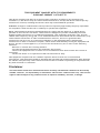
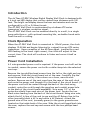
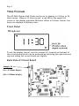
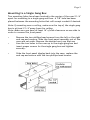
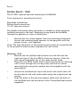
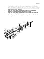
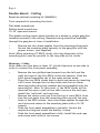
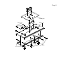
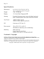
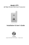
Wireless Digital Wall Clock
Model AT-DDC4
Installation & User’s Guide
THIS EQUIPMENT COMPLIES WITH FCC REQUIREMENTS
PURSUANT SUBPART J OF PART-15
This device complies with Part 15 of the FCC Rules. Operation is subject to the following two
conditions: (1) this device may not cause harmful interference, and (2) this device must accept any
interference received, including interference that may cause undesired operation.
WARNING: Changes or modifications to this product not expressly approved by the party responsible
for compliance could void the user’s authority to operate this equipment.
NOTE: This equipment has been tested and found to comply with the limits for a digital device,
pursuant to Part 15 of the FCC Rules. These limits are designed to provide reasonable protection
against harmful interference in a residential installation. This equipment generates, uses, and can
radiate radio frequency energy and, if not installed and used in accordance with the instructions, may
cause harmful interference to radio communications. However, there is no guarantee that
interference will not occur in a particular installation. If this equipment does cause harmful
interference to radio or television reception, which can be determined by turning the equipment off
and on, the user is encouraged to try to correct the interference by one or more of the following
measures:
- Reorient or relocate the receiving antenna.
- Increase the separation between the equipment and receiver.
- Connect the equipment into an outlet on a circuit different from that to which the receiver is
connected.
- Consult the dealer or an experienced radio TV technician for help.
This equipment complies with FCC radiation exposure limits set forth for an uncontrolled
environment. This equipment should be installed and operated with minimum distance 20cm between
the radiator and your body. This Transceiver must not be co-located or operating in conjunction with
any other antenna or Transceiver.
Disclaimer
The information within this document has been carefully checked and is believed to be entirely
reliable. However, no responsibility is assumed for inaccuracies. Lathem Time Corp. reserves the
right to make changes to any products herein to improve reliability, function, or design.
Page 1
Introduction
The AirTime AT-DDC Wireless Digital Display Wall Clock is designed with
a 4-inch red LED display that can be viewed from distances over 100
feet. The bright red display shows the hour and minutes and can be
configured for a 12 or 24 Hour format.
The AT-DDC Wall Clock is synchronized by a Lathem ATX series
transceiver’s wireless correction signal.
The AT-DDC Wall Clock can be mounted directly to a wall, to a single
gang outlet box or, with optional mounting kits, as double-faced units
from the wall or ceiling.
Clock Operation
When the AT-DDC Wall Clock is connected to 110vAC power, the clock
displays 12:00 AM and begins listening for a signal from an ATX series
transceiver. Upon reception of the AirTime signal, (verified by a red
LED flashing in the lower right corner), the clock will adjust to the
correct time. The clock will continue to listen and correct itself as
needed.
Power Cord Installation
A 3 wire grounded power cord is required. If the power cord will not be
in conduit, secure the power cord with a cable clamp into the selected
vent cap.
Remove the two phillips head screws from the left or the right end cap
and remove. Slide the circuit board out of the case. Carefully flip the
circuit board over and lay it face down on a clean, smooth work
surface. Remove one of the vent caps from the case of the wall clock
and route the power cord through it to the back of the circuit board. (If
the power cord will be routed through the back of the clock using
conduit, route the cord through the gang box and conduit access hole
to the back of the circuit board assembly). Strip away 1/2" of the
protective shield from each wire of the power cord. Locate the two
black wires leading from the back of the circuit board. Using wire nuts,
attach the AC In line of the cord to one and the AC Return line to the
other (normally black is AC In and white is AC Return). Attach the
ground wire of the cord, (normally green) to the green ground screw
located on the inside back of the case. Slide the circuit board back into
the case, replace the end cap and secure with the two phillips head
screws.
Page 2
Time Formats
The AT-DDC4 Series Wall Clocks can be set to display in 12 Hour or 24
Hour format. When in 12 Hour format, a red LED in the upper left
corner of the display indicates PM hours. When in 24 Hour format, the
hours are displays in Military style.
Front Panel
To set the display format, use the jumper (J1) located on the back of
the circuit board which can be accessed by removing the right side end
cap and sliding the circuit board out slightly.
Back Side of Circuit Board
Jumper J1
On = 12 Hour display
Off = 24 Hour display
Page 3
12 Hour Format
AM
PM
24 Hour Format
AM
PM
Page 4
Mounting
The AT-DDC Wall Clock can be mounted directly to a wall, to a single
gang outlet box, double hung from the wall or double hung from the
ceiling. When deciding where the clock will be mounted, keep in mind
that 115VAC power is required.
Mounting to a Wall
Tools required for mounting the clock:
Drill with a 5/16" bit
Hammer
Phillips head screwdriver
Wall anchors
Pencil
After deciding the location where the clock will be mounted,
make two marks 12" apart and horizontal.
Note: If mounting near a ceiling, make sure the holes are at least
2 1/4" away from the ceiling.
»
Note: Make sure you have at least 16" of side clearance on one side in
order to remove the front panel.
»
»
»
»
»
»
Drill a 5/16" hole at each mark
Insert a wall anchor and tap it flush to the wall with the
hammer.
Insert a screw into each wall anchor leaving 1/4" exposed.
Remove the two phillips head screws from the left or the right
end cap and remove. Slide the front panel assembly out of the
case and set aside.
Line up the two keyholes on the back of the case and slip over
the two screws and tighten securely. ( The lower mounting
holes can be marked at this point, the case removed, holes
drilled and wall anchors installed if so desired)
Slide the front panel display back into the case, replace the
end cap and secure with the two phillips head screws.
Page 5
Mounting to a Single Gang Box
Two mounting holes have been located in the center of the case 2 1/4"
apart for mounting to a single gang wall box. A 7/8" hole has been
placed between the mounting holes that will accept conduit if desired.
Note: If mounting near a ceiling, make sure the top of the single gang
box is at least 2 1/4" away from the ceiling.
Note: Make sure you have at least 16" of side clearance on one side in
order to remove the front panel.
»
»
»
Remove the two phillips head screws from the left or the right
end cap and remove. Slide the front panel assembly out of the
case and set aside. Remove the desired vent cap that any
Line the two holes in the case up to the single gang box and
insert proper screws for the single gang box and tighten
securely.
Slide the front panel display back into the case, replace the
end cap and secure with the two phillips head screws.
Page 6
Double Mount – Wall
The AT-DDC requires optional mounting kit (SAM0625)
Tools required for mounting the clock:
Flat blade screwdriver
Phillips head screwdriver
15/16" open end wrench
The double wall mount plate attaches to a double or single gang box
installed securely in the wall. Required wiring should be available
through the gang box at time of installation.
Remove the two chase nipples from the mounting plate posts.
Secure the mounting plate securely to the gang box with the
proper screws. (not supplied)
Note: The long dimension of the mounting plate must be perpendicular
to the ground to assure proper alignment of wall clocks.
»
»
Mounting - Wall
Remove the two phillips head screws from the left and the
»
right end caps of the two DDC4 clocks and remove. Slide the
front panel assemblies out of the cases and set aside.
»
Place the two DDC4 clocks back to back and secure by inserting
a #10 screw through the two key holes and the two lower
mounting holes using lock washers and nuts supplied with the
mounting kit.
»
»
Attach the modified end cap to the end of the clocks that will
be attached to the wall mount plate using the original end cap
screws.
Align the holes of the end cap support plate with the holes in
the modified end cap and secure with 4 #6 phillips head screws
(supplied)
Page 7
»
»
»
»
Line the two posts from the mounting plate up with the two
holes of the modified end cap. Insert the chase nipples through
the holes of the modified end cap and secure to the mounting
plate with a 15/16" wrench.
Slide the front panel assemblies in partially. Secure the
required wiring and install the battery if used.
Slide the front panel assemblies in fully. Install the end caps
and secure each with its two screws.
Discard or store the two original end caps the modified end
caps replaced.
mounting plate
modified end caps
DDC4 cases
end cap support
#10 hex nuts
#10 lock washers
chase nipples
#10 lock washers
#10 screws
Page 8
Double Mount - Ceiling
Requires optional mounting kit (SAM0626)
Tools required for mounting the clock:
Flat blade screwdriver
Phillips head screwdriver
15/16" open end wrench
The double ceiling mount plate attaches to a double or single gang box
installed securely in the ceiling. Required wiring should be available
through the gang box at time of installation.
Remove the two chase nipples from the mounting plate posts.
Secure the mounting plate securely to the gang box with the
proper screws. (not supplied)
Note: When mounting AT-DDC4 clocks, the long dimension of the
mounting plate must be parallel to the long side of the clocks.
»
»
Mounting - Ceiling
Note: Make sure you have at least 16" of side clearance on one side in
order to remove the front panel assembly.
»
»
»
»
»
»
Remove the two phillips head screws from the left and the
right end caps of the two DDC4 clocks and remove. Slide the
front panel assemblies out of the cases and set aside.
Place the two DDC4 clocks back to back and secure by inserting
a #10 screw through the two key holes and the two lower
mounting holes using lock washers and nuts supplied with the
mounting kit. Note: At this point, if the DDC4 clocks will be
mounted too near a wall on one side to secure the end caps,
install the "wall side" end caps now.
Remove the center vent cap from the top of each DDC4 clock.
Line the two posts from the mounting plate up with the vent
holes of the DDC4 clocks. Insert the chase nipples through the
vent holes and secure to the mounting plate with a 15/16"
wrench.
Slide the front panel assemblies in partially. Secure the
required wiring and install the battery if used.
Slide the front panel assemblies in fully. Install the end caps
and secure each with its two screws.
Page 9
mounting plate
#10 hex nuts
D DC4 cases
chase nipple
chase nipple
#10 lock washers
#10 screws
Page 10
Specifications
Dimensions
Weight
6 3/4" H X 15 1/2" W X 3 1/8" D
17.1 cm H X 39 cm W X 7.9 cm D
9 lbs. (4.086 kg)
Display
3 3/4-Inch Red 4 Segment LED
Housing
Extruded aluminum main case with black textured
paint, molded plastic end caps with black texture.
Line Power
115VAC, 80mA typical
220VAC, 80mA typical (optional)
FCC
Conforms to FCC Part 15
Environment
32o to 150 o F (0 o to 65 o C)
95% Relative Humidity (non-condensing)
Mounting
Wall (surface)
Single Gang Box (surface)
Double Face (wall or ceiling) (optional)
Trademark / Copyright
AirTime, Lathem and the Lathem logo are registered trademarks of Lathem Time
Corporation. Other product names mentioned in this manual may be trademarks of their
respective companies and are hereby acknowledged.
WARNING: Changes or modifications to this product not expressly approved by the party
responsible for compliance could void the user’s authority to operate this equipment.
Copyright © 2009 Lathem Time Corporation. All rights reserved.
Page 11
One Year Limited Warranty
Lathem warrants the hardware products described in this guide against
defects in material and workmanship for a period of one year from date
of original purchase from Lathem or from an authorized Lathem reseller.
The conditions of this warranty and the extent of the responsibility of
Lathem Time Corporation (“Lathem”) under this warranty are listed
below.
1. This warranty will become void when service performed by anyone other than an
approved Lathem warranty service dealer results in damage to the product.
2. This warranty does not apply to any product which has been subject to abuse,
3.
4.
5.
6.
7.
8.
9.
neglect, or accident, or which has had the serial number altered or removed, or
which has been connected, installed, adjusted, or repaired other than in accordance
with instructions furnished by Lathem.
This warranty does not cover dealer labor cost for removing and reinstalling the
machine for repair, or any expendable parts that are readily replaced due to normal
use.
The sole responsibility of Lathem under this warranty shall be limited to repair of
this product, or replacement thereof, at the sole discretion of Lathem.
If it becomes necessary to send the product or any defective part to Lathem or any
authorized service dealer, the product must be shipped in its original carton or
equivalent, fully insured with shipping charges prepaid. Lathem will not assume any
responsibility for any loss or damage incurred in shipping.
WARRANTY DISCLAIMER AND LIMITATION OF LIABILITY: Except only the limited
express warranty set forth above, the products are sold with no expressed or
implied warranties of any kind, and the implied warranties of merchantability and
fitness for a particular purpose are hereby expressly disclaimed. No warranties are
given with respect to products purchased other than from Lathem or an authorized
Lathem reseller and any such products are purchased "as is, with all faults." In no
event will Lathem be liable for any direct, indirect, special, incidental or
consequential damages arising out of or in connection with the delivery, use or
inability to use, or performance of this product. In the event any limited remedy
given herein shall be deemed to have failed of its essential purpose, Lathem's
maximum liability shall be to refund the purchase price upon return of the product.
Proof of date of purchase from Lathem or an authorized Lathem reseller is required
for warranty service on this product.
This Warranty grants specific legal rights. Additional legal rights, which may vary by
locale, may also apply.
Should any difficulties arise with the performance of this product during warranty,
or with any Lathem authorized service centers, contact Lathem Time at the
address below:
Lathem Time
200 Selig Drive, SW
Atlanta, GA 30336
www.lathem.com
Document Number: USG0084