1
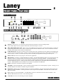
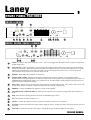
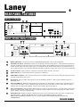
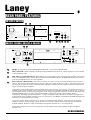
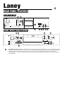
Laney
DB SERIES
USER MANUAL
MODEL : DB150C
DB150H
DB300C
DB300H
DB400C
DB400H
Laney
1
INTRODUCTION
Congratulations on your decision to purchase a Laney amplifier.
Laney products are designed with ease of operation as a primary objective, however to ensure you derive the best from
your new amplifier, it is important you take time to read this user manual and to familiarise yourself with the control
functions and facilities available
BEFORE
SWITCHING ON
After unpacking your amplifier check that it is factory fitted with a three pin 'grounded' (or earthed) plug. Before
plugging into the power supply ensure you are connecting to a grounded earth outlet.
If you should wish to change the factory fitted plug yourself, ensure that the wiring convention applicable to the country
where the amplifier is to be used is strictly conformed to. As an example in the United Kingdom the cable colour code
for connections are as follows.
EARTH OR GROUND - GREEN/YELLOW
NEUTRAL - BLUE
LIVE - BROWN
This manual has been written for easy access of information. The front and rear panels of each unit are graphically
illustrated, with each control and feature numbered. For a description of the function of each control feature, simply
check the number with the explanations adjacent to each panel.
Your Laney DB bass amplifier has undergone a thorough two stage, pre-delivery inspection, involving actual play
testing, as well as valve burn in. Valves are one of the most important components in your Laney DB bass amp.
However they are also the most fragile component. The glass envelope and valve filaments can easily be damaged in
transit without any apparent signs of damage to the box, amp or valves.
When you first recieve your Laney DB bass amp, follow these simple procedures:
(i) Ensure that the amplifier is set at the correct voltage for the country it is to be used in.
(ii) Connect your instrument with a high quality shielded instrument cable. Use of cheap cables will compromise the
sound of your instrument and your amplifier.
If there is a problem with your Laney DB bass amplifier
DON'T
DO
PHONE YOUR DEALER!
Care of your Laney amplifier will prolong it's life.....and yours!.
DB BASS MANUAL
Laney
2
FRONT PANEL FEATURES
DB150C & DB150H
15
14
16
TREBLE
FET GAIN
LEVEL
LO
OK
3
HI
5
4
6
2
7
2
8
1
0
10
4
3
5
5
3
4
5
6
PASSIVE
8
1
1
PRE
2
4
5
6
2
7
2
MID
8
1
9
10
0
INPUT
3
7
FET TUBE 2
HI
0
0
10
8
9
0
EQ
10
1
DB150C
0
NOISE
LIMIT GATE
4
5
5
PRESHAPE
BASS
5
6
4
3
7
1
3
POWER
6
2
2
4
TUBE POST
0
1 -0+ 1
3
9
5
3
4
PREAMPS
ACTIVE
VOLUME
2
4
9
GRAPHIC EQ
1 -0+ 1
3
40Hz 80Hz 160Hz320Hz 650Hz 1k3Hz2k6Hz 5kHz 10kHz
BALANCE
13
8 9 10 11 12
7
DB300C, DB300H, DB400C & DB400H
22
21
SUSTAIN
FET GAIN
4
LEVEL
LO
OK
5
6
4
3
HI
8 ON
1
8
4
5
6
3
0
INPUT
17 18
4
8
1
PRE
10
5
6
TUBE
4
8 ON
1
0
8
9
10
POST
ON
5
5
0
8
0
MID
HI
5
PRESHAPE
5
6
1
7
8
1
EQ
3
5
2
2
3
4
9
10
LEVEL
0
1-0+ 1
2
7
1
3
4
5
6
2
4
3
4
10
VOLUME
2
3
9
0
3
7
2
9
2
7
1
GRAPHIC EQ
1-0+ 1
6
COMPRESSOR
3
7
2
5
2
9
10
0
PREAMPS
PAD
4
3
7
1
10
TREBLE
ATTACK
6
2
9
0
5
3
7
2
DB300H
0
9
0
10 LIMIT NOISE
GATE
POWER
4
40Hz 80Hz 160Hz 320Hz 650Hz 1k3Hz2k6Hz 5kHz 10kHz
BALANCE
BASS
19 20
1
INPUTS: Active Input: Low sensitivity input for instrument with active circuitry and high output.
Passive Input: High sensitivity input for instrument with normal output i.e. Passive.
2
PRE AMP MODE SELECTOR: Allows access to the different pre amp modes. Pre amp mode selection is achieved
by depressing the relevant switch. With no switches depressed the unit defaults to FET. To access both FET and Tube
pre amp sections depress both switches simultaneously.
3
TUBE PRE GAIN: Sets the level of drive in the Tube pre amp circuit. Should be used in conjunction with POST gain
control to achieve the desired sound. To achieve a clean sound set the PRE gain level low whilst setting the POST gain
relatively high. To achieve a saturated pre amp sound set the PRE gain high and the POST gain relatively low.
4
POST GAIN: Sets the level of post gain. See above for application.
5
PRE-SHAPE: Two factory set PRE-SHAPES are available. The MID PRE SHAPE produces an overall dip in the mid
frequency responce of the amp whilst at the same time boosting the low end of the amplifier. The HI PRE SHAPE
boosts the upper end frequency response of the amplifier. Both these PRE SHAPES can be selected simultaneously to
provide a third factory pre set. These pre shapes can be further modified by the units BASS, MID and GRAPHIC EQ
sections. PRE SHAPES are footswitchable on all models except DB150C and DB150H.
6
BASS: Controls the overall bass response of the amplifier
7
GRAPHIC: Nine band GRAPHIC. When switched out the EQ will be set in a flat frequency response. Voicings set via
the PRE-SHAPE can be further modified using the GRAPHIC.
8
BALANCE: Balances the pre amplifier output level when the GRAPHIC is assigned. Raising the slider increases the
output level of the GRAPHIC. Lowering the slider cuts the output of the GRAPHIC. BALANCE has no effect when
EQ is not selected
9
EQ: Enables the onboard GRAPHIC. The GRAPHIC can also be switched via a footswitch on all models. FS2
DB150C/DB150H FS4 footswitch. on all remaining models.
10
VOLUME: Sets the overall listening level of the amplifier
DB BASS MANUAL
Laney
3
FRONT PANEL FEATURES
DB150C & DB150H
15
14
16
TREBLE
FET GAIN
LEVEL
LO
OK
3
HI
5
4
6
2
7
2
8
1
0
10
4
3
5
5
3
4
5
6
PASSIVE
8
1
1
PRE
2
4
5
6
2
7
2
MID
8
1
9
10
0
INPUT
3
7
FET TUBE 2
HI
0
0
10
8
9
0
EQ
10
1
DB150C
0
NOISE
LIMIT GATE
4
5
5
PRESHAPE
BASS
5
6
4
3
7
1
3
POWER
6
2
2
4
TUBE POST
0
1 -0+ 1
3
9
5
3
4
PREAMPS
ACTIVE
VOLUME
2
4
9
GRAPHIC EQ
1 -0+ 1
3
40Hz 80Hz 160Hz320Hz 650Hz 1k3Hz2k6Hz 5kHz 10kHz
BALANCE
13
8 9 10 11 12
7
DB300C, DB300H, DB400C & DB400H
22
21
FET GAIN
4
LEVEL
LO
OK
5
SUSTAIN
6
4
3
HI
8 ON
1
4
5
8
1
10
6
3
0
INPUT
17 18
4
8
1
PRE
10
5
6
TUBE
4
8 ON
0
1
9
10
POST
ON
5
5
0
8
0
MID
HI
5
PRESHAPE
5
6
1
7
8
1
EQ
3
5
2
2
3
4
9
10
LEVEL
0
1-0+ 1
2
7
1
3
4
5
6
2
4
3
4
10
VOLUME
2
3
9
0
GRAPHIC EQ
1-0+ 1
2
7
8
3
7
1
TREBLE
6
COMPRESSOR
2
9
5
2
9
10
0
3
7
2
4
3
7
PREAMPS
PAD
ATTACK
6
2
9
0
5
3
7
2
DB300H
0
9
0
10 LIMIT NOISE
GATE
POWER
4
40Hz 80Hz 160Hz 320Hz 650Hz 1k3Hz2k6Hz 5kHz 10kHz
BALANCE
BASS
19 20
11
LIMIT: Activates a fast attack compressor circuit. This is auto triggered by the output section, and prevent distortion
at high output levels.
12
NOISE GATE: When the amplifier is set for a high gain and high output volume; noise, hum and acoustic feedback
may become apparent. When selected (Pressed in) the noise reduction circuit is activated when playing ceases, greatly
reducing the unwanted noise. Note this is designed to be used at high gain and volme levels, use at low levels can
cause unwanted noise and result in premature signal cut off.
13
POWER: Illuminates when amplifier is switched on.
14
LEVEL INDICATORS: Indicates the strength of signal present in the pre-amplifier. If an ORANGE LED is
displayed the level of signal should be increased by means of the Pre-amp gains, using the appropriate gain controls. If
a GREEN LED is displayed the signal is at its optimum level. If a RED LED is displayed then the level present is too
high and should be adjusted accordingly.
15
FET GAIN: Adjusts the level of gain for the FET (solid state) section of the pre amp. This control is only active if the
FET pre amp selector is assigned or if both pre amp modes are selected simultaneously
16
TREBLE: Controls the HIGH level frequency content of the amplifier.
17
COMBINATION XLR/JACK INPUT: Allows for the connection of an instrument using either XLR connectors of
Jacks
18
PAD: Pad switch for selecting between ACTIVE and PASSIVE input sources.
19
ON: Switches the on board compressor on.
20
LEVEL: Controls the output level of the compressor when the compressor is switched on.
21
SUSTAIN: Controls the compression range and the length of sustain. Turning the control clockwise increases the level
of sustain.
22
ATTACK: Controls the envelope of the signal. Turning the control clockwise emphasizes the attack.
DB BASS MANUAL
Laney
4
REAR PANEL FEATURES
DB150C & DB150H
23
24
WARNING THIS EQUIPMENT MUST BE EARTHED.
MAXIMUIM POWER
CONSUMPTION 300 WATTS ~50 - 60 Hz.
SPEAKER OUTPUT
HORN
8P-86
CE
SUPPLY VOLTAGE ~230V
& FUSE RATING ~115V
OFF
T1A
T2A
PIN -1 = GND.
PIN +1 = SIG.
A TOTAL LOAD OF NO LESS THAN 8 OHMS
CAN BE CONNECTED AT ANY ONE TIME.
CAUTION
TO REDUCE THE RISK OF
FIRE HAZARD REPLACE FUSE WITH
SAME TYPE AND RATING ONLY.
ATTENTION
REMPLACER LE FUSIBLE
SERIAL No:
PREAMP OUT
PAR LE MEME ET LE CALIBRE.
DEBRANCHER A LA PRISE
ATTENTION
SECTEUR AVAVT D'OUVRIR.
CAUTION
TO REDUCE THE RISK
OF FIRE OR ELECTRIC SHOCK DO
NOT EXPOSE THIS APPLIANCE TO
RAIN OR MOISTURE.
FX LOOP
POST EQ.
SEND
PRE/POST
EQ
TO REDUCE THE RISK OF ELECTRIC SHOCK DO NOT
REMOVE COVERS. NO USER SERVICABLE PARTS INSIDE.
WARNING
FX LOOP
PRE EQ.
SEND
DIRECT INJECT
REFER SERVICING TO QUALIFIED SERVICE PERSONNEL.
MADE IN THE UNITED KINGDOM BY BLT INDUSTRIES LTD.
RETURN
25
26
DB300C, DB300H, DB400C & DB400H
32 33
FOOTSWITCH
30 31
34
WARNING THIS EQUIPMENT MUST BE EARTHED.
35
PREAMP OUT
MAXIMUIM POWER
SPEAKER OUTPUT
CONSUMPTION 500 WATTS ~50 - 60 Hz.
HORN
CE
27 28 29
RETURN
ELECTRONIC CROSSOVER
8P-8687
HI OUT
HI
LEVEL
SPLIT
LO
MID
HI
2
1-0+ 1
2
3
OFF
LO
SUPPLY VOLTAGE ~230V T6.3A
& FUSE RATING ~115V T10A
PIN -1 = GND.
PIN +1 = SIG.
A TOTAL LOAD OF NO LESS THAN 8 OHMS
CAN BE CONNECTED AT ANY ONE TIME
CAUTIONTO REDUCE THE RISK OF ELECTRIC SHOCK DO NOT
4
FX LOOP
FX LOOP
PRE EQ.
POST EQ.
SEND
SEND
RETURN
RETURN
PRE/POST
EQ
REMOVE COVERS. NO USER SERVICABLE PARTS INSIDE.
REFER SERVICING TO QUALIFIED SERVICE PERSONNEL.
}
OF FIRE OR ELECTRIC SHOCK DO
NOT EXPOSE THIS APPLIANCE TO
RAIN OR MOISTURE.
5
DIRECT INJECT
PAR LE MEME ET LE CALIBRE.
ATTENTION DEBRANCHER A LA PRISE
SECTEUR AVAVT D'OUVRIR.
WARNINGTO REDUCE THE RISK
5
POWER AMP IN
SERIAL No:
CAUTION TO REDUCE THE RISK OF
FIRE HAZARD REPLACE FUSE WITH
SAME TYPE AND RATING ONLY.
ATTENTION REMPLACER LE FUSIBLE
3
4
LO OUT
MADE IN THE UNITED KINGDOM BY BLT INDUSTRIES LTD.
FOOTSWITCH
36
23
HORN SWITCH: Activates the on board COMPRESSION DRIVER. Not present on DB150H.
24
SPEAKON OUTPUT: SPEAKON connector for connecting external speaker cabinet. Total minimum impedance of
enclosure connected to this socket must be no lower than 8 Ohm (4 Ohm DB400C/H) when used in conjunction with
another cabinet either connected to jack socket (25) or linked from the cabinet connected to the speakon connector. If
only a single enclosure is to be used the minimum impedance should be no lower than 4 Ohm. Not present on DB150C
25
JACK OUTPUT: JACK socket for connection of external speaker enclosure. See above.
26
PRE AMP OUT: Provides output to drive external power amplifier.
27
XLR DIRECT INJECT: XLR socket for output of low impedance balanced line signal. Provides signal for use with
external mixing desks or PA system
28
DI SELECT: Selects whether the signal sent to the XLR DIRECT INJECT is derived from a PRE EQ signal or a
POST EQ signal.
29
FX LOOP PRE EQ: SEND & RETURN jacks for connection of external effects. Effects units connected to this set
of send and return sockets receive a PRE EQ signal. Should be used in conjunction with any effect which is going to
radically alter the sound of the amplifier, such as Octave dividers, distortion pedals etc.
30
FX LOOP POST EQ: SEND & RETURN jacks for the connection of external effects. An effect unit(s) connected to
this set of send and return sockets will recieve a POST EQ signal. Should be used in conjunction with effects such as
chorus, flanger or any type of digital pedal.
31
FOOTSWITCH: Should be used for connecting the correct type of footswitch to allow the remote switching of the
following features. DB150C & DB150H, FS2 for switching of GRAPHIC and INPUT MODE.
DB300C/DB300H/DB400C/DB400H, FS5 for switching of INPUT MODE/PRE SHAPE/GRAPHIC and
COMPRESSOR
DB BASS MANUAL
Laney
5
REAR PANEL FEATURES
DB150C & DB150H
23
24
WARNING THIS EQUIPMENT MUST BE EARTHED.
MAXIMUIM POWER
CONSUMPTION 300 WATTS ~50 - 60 Hz.
SPEAKER OUTPUT
HORN
8P-86
CE
SUPPLY VOLTAGE ~230V
& FUSE RATING ~115V
OFF
T1A
T2A
PIN -1 = GND.
PIN +1 = SIG.
A TOTAL LOAD OF NO LESS THAN 8 OHMS
CAN BE CONNECTED AT ANY ONE TIME.
CAUTION
TO REDUCE THE RISK OF
FIRE HAZARD REPLACE FUSE WITH
SAME TYPE AND RATING ONLY.
ATTENTION
REMPLACER LE FUSIBLE
SERIAL No:
PREAMP OUT
PAR LE MEME ET LE CALIBRE.
DEBRANCHER A LA PRISE
ATTENTION
SECTEUR AVAVT D'OUVRIR.
CAUTION
TO REDUCE THE RISK
OF FIRE OR ELECTRIC SHOCK DO
NOT EXPOSE THIS APPLIANCE TO
RAIN OR MOISTURE.
FX LOOP
POST EQ.
SEND
PRE/POST
EQ
TO REDUCE THE RISK OF ELECTRIC SHOCK DO NOT
REMOVE COVERS. NO USER SERVICABLE PARTS INSIDE.
WARNING
FX LOOP
PRE EQ.
SEND
DIRECT INJECT
REFER SERVICING TO QUALIFIED SERVICE PERSONNEL.
MADE IN THE UNITED KINGDOM BY BLT INDUSTRIES LTD.
RETURN
25
26
DB300C, DB300H, DB400C & DB400H
32 33
FOOTSWITCH
30 31
34
WARNING THIS EQUIPMENT MUST BE EARTHED.
35
PREAMP OUT
MAXIMUIM POWER
SPEAKER OUTPUT
CONSUMPTION 500 WATTS ~50 - 60 Hz.
HORN
CE
27 28 29
RETURN
ELECTRONIC CROSSOVER
8P-8687
HI OUT
HI
LEVEL
SPLIT
LO
MID
HI
2
1-0+ 1
2
3
OFF
LO
SUPPLY VOLTAGE ~230V T6.3A
& FUSE RATING ~115V T10A
PIN -1 = GND.
PIN +1 = SIG.
A TOTAL LOAD OF NO LESS THAN 8 OHMS
CAN BE CONNECTED AT ANY ONE TIME
CAUTIONTO REDUCE THE RISK OF ELECTRIC SHOCK DO NOT
4
FX LOOP
FX LOOP
PRE EQ.
POST EQ.
SEND
SEND
RETURN
RETURN
PRE/POST
EQ
REMOVE COVERS. NO USER SERVICABLE PARTS INSIDE.
REFER SERVICING TO QUALIFIED SERVICE PERSONNEL.
}
OF FIRE OR ELECTRIC SHOCK DO
NOT EXPOSE THIS APPLIANCE TO
RAIN OR MOISTURE.
5
DIRECT INJECT
PAR LE MEME ET LE CALIBRE.
ATTENTION DEBRANCHER A LA PRISE
SECTEUR AVAVT D'OUVRIR.
WARNINGTO REDUCE THE RISK
5
POWER AMP IN
SERIAL No:
CAUTION TO REDUCE THE RISK OF
FIRE HAZARD REPLACE FUSE WITH
SAME TYPE AND RATING ONLY.
ATTENTION REMPLACER LE FUSIBLE
3
4
LO OUT
MADE IN THE UNITED KINGDOM BY BLT INDUSTRIES LTD.
FOOTSWITCH
36
32
HORN: Activates the on board COMPRESSION DRIVER. Not present on DB300/400H.
33
HI/LO SWITCH: When switched to the HI position the HORN runs at full level. When switched to LO the HORN
is attenuated down -6db.
34
PRE AMP OUT POWER AMP IN: PRE AMP OUT provides output to drive external power amplifier. This may be
used as an additional FX loop when used in conjunction with POWER AMP IN. POWER AMP IN provides an input
to the power amplifier for use as a slave amplifier.
35
ELECTRONIC CROSSOVER: The crossover consists of a HI OUT a LO OUT, a SPLIT function and a LEVEL
control. The LEVEL control determines the level of signal sent to either the HI or LO output. The SPLIT control sets
the frequency at which the crossover functions and the HI and LO outputs provide a signal to either the internal power
amp or an external power amplifier.
Lets look at the following example to gain an insight into how the crossover can be set up. Lets assume that you have a
DB400C and you wish to employ a 1x15 cabinet with a seperate power amplifier to handle the bottom end. To do this
you would first need to set the crossover frequency to LO. Using a straight Jack connector, connect the HI output to the
POWER AMP IN socket (34), This routes the HI frequency signal to the internal power amplifier which is
subsequently handled by the onboard speakers . Using a second jack connect the LO OUT socket to the input socket
of the external power amplifier connected to the 1x15 enclosurer. The DB400C will handle all the MID/HI frequencies
whilst the 1x15 will handle all the LO end.
To split the signal to allow a seperate 2 x 10" enclosure to handle the HI frequencies whist allowing the onboard
speaker to carry the remaining signal, patch the crossover as follows, SPLIT selector to HI, LO OUT connected to
POWER AMP IN, HI OUT to input of external power amplifier connected to 2 x 10" extension cab.
With nothing connected to the crossover patch bay, the unit defaults to full range regardless of where the SPLIT
function is set.
DB BASS MANUAL
Laney
6
REAR PANEL FEATURES
DB150C & DB150H
23
24
WARNING THIS EQUIPMENT MUST BE EARTHED.
MAXIMUIM POWER
CONSUMPTION 300 WATTS ~50 - 60 Hz.
SPEAKER OUTPUT
HORN
8P-86
CE
SUPPLY VOLTAGE ~230V
& FUSE RATING ~115V
OFF
T1A
T2A
PIN -1 = GND.
PIN +1 = SIG.
A TOTAL LOAD OF NO LESS THAN 8 OHMS
CAN BE CONNECTED AT ANY ONE TIME.
CAUTION
TO REDUCE THE RISK OF
FIRE HAZARD REPLACE FUSE WITH
SAME TYPE AND RATING ONLY.
ATTENTION
REMPLACER LE FUSIBLE
SERIAL No:
PREAMP OUT
PAR LE MEME ET LE CALIBRE.
DEBRANCHER A LA PRISE
ATTENTION
SECTEUR AVAVT D'OUVRIR.
CAUTION
TO REDUCE THE RISK
OF FIRE OR ELECTRIC SHOCK DO
NOT EXPOSE THIS APPLIANCE TO
RAIN OR MOISTURE.
FX LOOP
POST EQ.
SEND
PRE/POST
EQ
TO REDUCE THE RISK OF ELECTRIC SHOCK DO NOT
REMOVE COVERS. NO USER SERVICABLE PARTS INSIDE.
WARNING
FX LOOP
PRE EQ.
SEND
DIRECT INJECT
REFER SERVICING TO QUALIFIED SERVICE PERSONNEL.
MADE IN THE UNITED KINGDOM BY BLT INDUSTRIES LTD.
RETURN
25
26
DB300C, DB300H, DB400C & DB400H
32 33
FOOTSWITCH
30 31
34
WARNING THIS EQUIPMENT MUST BE EARTHED.
35
PREAMP OUT
MAXIMUIM POWER
SPEAKER OUTPUT
CONSUMPTION 500 WATTS ~50 - 60 Hz.
HORN
CE
27 28 29
RETURN
ELECTRONIC CROSSOVER
8P-8687
HI OUT
HI
LEVEL
SPLIT
LO
MID
HI
2
1-0+ 1
2
3
OFF
LO
SUPPLY VOLTAGE ~230V T6.3A
& FUSE RATING ~115V T10A
PIN -1 = GND.
PIN +1 = SIG.
A TOTAL LOAD OF NO LESS THAN 8 OHMS
CAN BE CONNECTED AT ANY ONE TIME
CAUTIONTO REDUCE THE RISK OF ELECTRIC SHOCK DO NOT
4
FX LOOP
FX LOOP
PRE EQ.
POST EQ.
SEND
SEND
RETURN
RETURN
PRE/POST
EQ
REMOVE COVERS. NO USER SERVICABLE PARTS INSIDE.
REFER SERVICING TO QUALIFIED SERVICE PERSONNEL.
}
OF FIRE OR ELECTRIC SHOCK DO
NOT EXPOSE THIS APPLIANCE TO
RAIN OR MOISTURE.
5
DIRECT INJECT
PAR LE MEME ET LE CALIBRE.
ATTENTION DEBRANCHER A LA PRISE
SECTEUR AVAVT D'OUVRIR.
WARNINGTO REDUCE THE RISK
5
POWER AMP IN
SERIAL No:
CAUTION TO REDUCE THE RISK OF
FIRE HAZARD REPLACE FUSE WITH
SAME TYPE AND RATING ONLY.
ATTENTION REMPLACER LE FUSIBLE
3
4
LO OUT
MADE IN THE UNITED KINGDOM BY BLT INDUSTRIES LTD.
FOOTSWITCH
36
36
SPEAKER OUTPUT JACKS: JACKconnectors for connecting external speaker cabinet . Total minimum impedance
of enclosure connected to this socket must be no lower than 8 Ohm (4 Ohm DB400C/H) when used in conjunction with
onboard speaker, another cabinet either connected to jack socket (25) or linked from the cabinet connected to the
speakon connector. If only a single enclosure is to be used the minimum impedance should be no lower than 4 Ohm (2
Ohm DB400H)
BLT Industries Ltd.,
Newlyn Road,
Cradley Heath,
West Midlands.
B64 6BE.
Tel: (0044) (0)1384 633821
Fax: (0044) (0)1384 639186
Http://www.laney.co.uk
In the interest of continued product development BLT Industries Ltd. Reserves the
right to amend product specification wihtout prior notification.