1
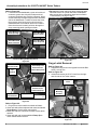
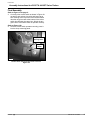
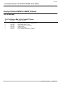
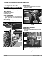
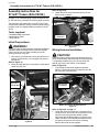
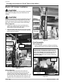
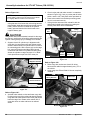
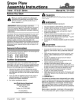
Electric Bed Lift
Assembly Instructions
Treker 4200/4400 ST / NT & 4210/4410 ST Series
Before You Start
!
When you see this symbol, the subsequent
instructions and warnings are serious - follow
without exception. Your life and the lives of
others depend on it!
These optional assembly instructions contain only
information required to assemble the Electric Bed Lift to
the ST and NT Series Treker. A detailed Operator’s
Manual was supplied with the Treker. Refer to the
Operator’s Manual for additional specific information
especially information relating to safety concerns. Also
included in the Operator’s Manual is important
information on operation, adjustment, troubleshooting,
and maintenance for this attachment (some manual
sections do not apply to all options).
Manual No. 701-055M
Assembly Instructions for
4210ST & 4410ST Series Trekers
On page 6 is a detailed listing of parts included in this kit.
Use this list as a checklist to inventory parts received.
Tools required:
• Standard Blade Screwdriver
• Two - 7/16" wrenches
• One - 1/2" wrench
• Needle Nose Pliers
• Work Gloves
Initial Preparations
• Operator’s Manual (All NT & ST Series) . . 700-108M
• Parts Manual (4200/4400 NT/ST Series). . 700-108P
• Parts Manual (4210/4410 ST Series). . . . . 700-109P
1. Park vehicle on a level surface. Don’t work under or
around a vehicle parked on an incline.
2. Make the following gear and park brake selections:
a. 4200/4400 NT & ST Trekers:
•Set shift selector in forward gear.
•Set park brake.
b. 4210ST & 4410ST Trekers.
•Set shift selector in Park.
3. Turn ignition switch off and remove switch key.
General Information
Rocker Switch Installation
A separate Parts Manual for replacement parts can be
purchased from your dealer or available free of charge at
www.landpride.com. Have model and serial numbers
handy when placing an order.
Manual Part Numbers:
Instructions for 4210ST & 4410ST Trekers begin on
page 1. Instructions for 4200/4400 NT & ST Trekers with
serial number 418339 and up begin on page 7.
Instructions for 4200/4400 NT & ST Trekers with serial
number 418338 and below begin on page 11.
Refer to Figure 1A:
1. Remove panel plug from dump mounting panel by
prying with a straight bladed screwdriver under the
panel plug.
These assembly instructions apply to the Electric Bed Lift
Kit for the following options listed below:
701-071A
701-072A
Treker ST Series (S/N 418339+)
Treker NT Series (S/N 418339+)
701-044A
701-045A
Treker ST Series (S/N 418338-)
Treker NT Series (S/N 418338-)
Dump
Mounting
Panel
Aux
Mounting
Panel
Panel
Plugs
21470
NOTE: Insert a straight bladed screwdriver under panel plug
as indicated by white arrows to pry panel plug out.
Aux and Dump Panel Plugs
Figure 1A
© Copyright 2005 Printed
8/15/05
Manual No. 701-055M
1
Land Pride
Assembly Instructions for 4210ST & 4410ST Series Trekers
Refer to Figure 2A:
2. Locate behind the dashboard a green wire with red
connector, green wire with yellow stripe and red
connector and black wire with blue connector. Wires
can be located by looking through the left front fender
well at the dashboard. If unable to locate the wires,
then remove glove box by prying glove box from
dashboard with a screwdriver at its rivet locations.
Once the wires are located, pull them through the
dump mounting panel opening as shown.
Dump Mounting
Panel Opening
• Do not press rocker switch into dump mounting panel
until after electric lift cylinder has been installed and
after correct wiring connections have been verified in
“Final Assembly” on page 5 step 3.
Bed Latch
Lock-Up Arm
Green Wire With
Red Connector
Green Wire With
Yellow Stripe and
Black Wire With
Blue Connector
22481
21471
Bed Latch Lock-Up Arm
Figure 4A
Electrical Wiring & Mounting Panels
Figure 2A
Black Wire With
Blue Connector
Top
Terminal
Green Wire With
Yellow Stripe and
Red Connector
Labeled Dump down
Cargo Latch Removal
Refer to Figure 4A:
1. Support the cargo box in the up position with the Bed
Latch Lock-Up Arm.
Refer to Figure 5A:
2. Unbolt and remove the 5/16" U-bolt from the right
and left side of the Treker chassis.
Bed Latch
U-bolt
Green Wire With
Red Connector
Labeled Dump Up
Rocker Switch
This End Down
Bottom Terminal
Electric Lift
Mounting
Brackets
21472
Rocker Switch with Electrical Wiring attached
Figure 3A
Refer to Figure 3A:
3. Plug wires to rocker switch terminals as follows:
• Green wire with yellow stripe and red connector labeled
Dump Down to rocker switch top terminal.
• Black wire with blue connector to middle rocker switch
terminal.
• Green wire with red connectorlabeled Dump Up to
rocker switch bottom terminal.
2
23644
Bed Latch U-bolts (Right Side Shown)
Figure 5A
Manual No. 701-055M
■ 8/15/05
Land Pride
Assembly Instructions for 4210ST & 4410ST Series Trekers
Refer to Figure 6A:
3. Remove the two extension springs from the Bed
Latch Assembly.
4. Remove attaching hardware mounting the Bed Latch
Assembly. Attaching hardware consist of eight
1/4"-20 x 5/8" hex head cap screws, flat washers, hex
flange lock nuts and four latch keeper bars.
Extension
Spring
Attaching
Hardware
Electric Bed Lift
Electrical End
1/2" Clevis Pin
Bed Latch
Assembly
5/32" Cotter Pin
23646
Electric Lift Lower Mounting
Figure 7A
23465
Wiring Harness
T-shaped Connector
Bed Latch U-bolts (Left Side Shown)
Figure 6A
Electric Lift Cylinder Installation
Refer to Figure 7A & Figure 8A:
1. Attach the base of the Electric Bed Lift to the
mounting bracket (see Figure 8A for mounting
bracket location) with a 1/2" x 49/64" clevis pin.
Secure pin with 5/32" cotter pin. The rod end will be
attached to the cargo box later. Secure pin in place
by bending one leg of the cotter pin.
Refer to Figure 8A:
2. Locate the T-shaped connector mounted on the end
of the Treker wiring harness. Cut plastic tie securing
the T-shaped connector to the Treker frame.
Refer to Figure 9A:
3. Plug the T-shaped connector to the Electric Lift
connector.
IMPORTANT: The Electric Bed Lift is protected by an
internal clutch in both directions. When the up or
down travel limit is reached, the electric dump will
make a loud “ratchet” noise indicating end of travel
limit has been reached or the Electric Bed Lift is
overloaded. When this noise is heard, release the
switch immediately.
!
CAUTION!
!
CAUTION!
Treker Wiring
Harness
Mounting
Bracket
23644
Treker Wiring Harness for the Electric Lift
Figure 8A
Wiring Harness
T-shape Connector
Electric Lift
Connector
The cylinder needs to be extended to attach it to the cargo
box. Be very careful not to hit anything while extending the
cylinder causing bodily injury or damage to the vehicle.
Care should be taken when removing the Bed Latch LockUp Arm to prevent injury. Avoid pinch points and make
certain the cargo box does not fall when changing from
Bed Latch Lock-Up Arm to Electric Bed Lift Assembly.
8/15/05
■
21175
T-Shape Connector
Figure 9A
Manual No. 701-055M
3
Land Pride
Assembly Instructions for 4210ST & 4410ST Series Trekers
Refer to Figure 11A:
4. Do not connect rod end to cargo box until after
step 5. Extend the rod end of the electric lift until it is
approximately 1" from its connection point located
under the cargo box.
Refer to Figure 10A:
5. With a secure hold on the cargo box, un-hook the
Bed Latch Lock-Up Arm as shown.
Bed Latch Lock-Up Arm Removal
Refer to Figure 12A:
1. With a standard screwdriver, pry the torsion spring
off of the Bed Latch Lock-Up Arm.
Torsion Spring
Flat Bladed
Screwdriver
Bed Latch
Lock-Up Arm
Bed Latch
Lock-Up Arm
Locking Slot
Disengaged From
Treker Frame
Un-Hooking Torsion Spring
Figure 12A
Bed Latch Lock-Up Arm (Lower End)
Figure 10A
6. Manually align the cargo box connection holes with
the electric cylinder rod end. Attach rod end to the
cargo box with 1/2" x 49/64" clevis pin and 5/32"
cotter pin. Secure pin in place by bending one leg of
the cotter pin.
Refer to Figure 13A:
2. Straighten cotter pin and remove. Remove Flat
Washer, Bed Latch Lock-Up Arm, torsion spring and
bushing.
5/32" Cotter Pin
Torsion Spring
and Bushing
Cotter Pin
Flat Washer
1/2" Clevis Pin
Bed Latch
Lock-Up Arm
Electric Lift
Rod End
Rod End Connection
Figure 11A
4
Bed Latch Lock-Up Removal
Figure 13A
Manual No. 701-055M
■ 8/15/05
Land Pride
Assembly Instructions for 4210ST & 4410ST Series Trekers
Final Assembly
Refer to Figure 3A on page 2:
3. Correctly orient rocker switch as shown in Figure 3A
on page 2 and activate it to raise and lower cargo
box. Pushing at the top of the rocker switch should
raise the cargo box and at the bottom of the rocker
switch should lower the cargo box. Switch the two
green wires if the switch does not operate correctly.
Refer to Figure 14A:
4. Once the rocker switch operates correctly, press it
into the dump mounting panel.
Dump Switch
Mounting Panel
Rocker
Switch
21473
Rocker Switch Plugged to Electrical Connector
Figure 14A
8/15/05
■
Manual No. 701-055M
5
Land Pride
Assembly Instructions for 4210ST & 4410ST Series Trekers
Listing of Parts (4200ST & 4400ST Trekers)
Your kit includes:
701-071A Electric Bed Lift for Treker ST Series
6
Qty.
Part No.
Part Description
1
2
2
1
1
1
701-055M
805-045C
805-303C
833-254C
833-271C
833-317C
MANUAL ELECTRIC BED LIFT INSTRUCTION
PIN COTTER 5/32 X 1 1/4 LG
PIN CLEVIS 1/2X1 49/64 USABLE
DUMP SWITCH
SWITCH ACTUATOR
ELECT. LINEAR ACTUATOR 12" STROKE
Manual No. 701-055M
■ 8/15/05
Land Pride
Assembly Instructions for 4200/4400 ST & NT (S/N 418339+)
Assembly Instructions for
4200/4400 ST & NT (S/N 418339+)
Refer to Figure 2B:
3. Unbolt and remove bed latch lock-down from the
driver’s side of chassis.
On page 10 is a detailed listing of parts included in this
kit. Use this list as a checklist to inventory parts received.
Tools required:
• Standard Blade Screwdriver
• Needle Nose Pliers
• Work Gloves
Initial Preparations
1. Park vehicle on a flat surface, move gear shift lever to
neutral, set park brake, turn off engine and remove
ignition key.
Refer to Figure 1B:
2. Raise the cargo box fully up to support it with the Bed
Latch Lock-Up Arm.
Bed Latch
Lock-Down
21174
Bed Latch Lock-Down
Figure 2B
Rocker Switch Installation
Refer to Figure 3B:
1. Remove panel plug from dump mounting panel by
prying with a straight bladed screwdriver under the
panel plug.
Bed Latch
Lock-Up Arm
Dump
Mounting
Panel
Aux
Mounting
Panel
Panel
Plugs
21470
21173
Bed Latch Lock-Up Arm
Figure 1B
NOTE: Insert a straight bladed screwdriver under panel
plug as indicated by white arrows to pry panel plug out.
Aux and Dump Panel Plugs
Figure 3B
8/15/05
■
Manual No. 701-055M
7
Land Pride
Assembly Instructions for 4200/4400 ST & NT (S/N 418339+)
• Green wire with red connectorlabeled Dump Up to
Green Wire With
Red Connector
Dump Mounting
Panel Opening
Green Wire With
Yellow Stripe and
Black Wire With
Blue Connector
rocker switch bottom terminal.
• Do not press rocker switch in to dump mounting panel
until after electric lift cylinder has been installed and
after correct wiring connections have been verified in
“Final Assembly” on page 9 step 3.
Electric Lift Cylinder Installation
!
CAUTION!
!
CAUTION!
Securely support cargo box in the up position to prevent
injury while exchanging lock-up arm with Electric Lift
Cylinder.
21471
Electrical Wiring & Mounting Panels
Figure 4B
Refer to Figure 4B:
2. Locate behind the dashboard a green wire with red
connector, green wire with yellow stripe and red
connector and black wire with blue connector. Wires
can be located by looking through the left front fender
well at the dashboard. If unable to locate the wires,
then remove glove box by prying glove box from
dashboard with a screwdriver at its rivet locations.
Once the wires are located, pull them through the
dump mounting panel opening as shown.
Black Wire With
Blue Connector
Top
Terminal
Green Wire With
Yellow Stripe and
Red Connector
Labeled Dump down
Care should be taken when removing the Bed Latch LockUp Arm to prevent injury. Avoid pinch points and make
certain the cargo box does not fall when changing from
Bed Latch Lock-Up Arm to Electric Bed Lift Assembly.
Refer to Figure 6B
1. Support the cargo box in the up position with a
device other than the Bed Latch Lock-Up Arm to
relive tension on the connecting pins.
2. Remove existing cotter pins and clevis pins located
at both ends of the Bed Latch Lock-Up Arm. Remove
lock-up arm from vehicle.
Cotter and
Clevis Pins
Bed Latch
Lock-Up Arm
Latch Pin
Spring Loaded
Latch
Green Wire With
Red Connector
Labeled Dump Up
Rocker Switch
This End Down
Bottom Terminal
21472
Rocker Switch with Electrical Wiring attached
Figure 5B
Refer to Figure 5B:
3. Plug wires to rocker switch terminals as follows:
• Green wire with yellow stripe and red connector labeled
Dump Down to rocker switch top terminal.
• Black wire with blue connector to middle rocker switch
terminal.
8
Cotter and
Clevis Pins
21173
Rocker Switch Connection
Figure 6B
Manual No. 701-055M
■ 8/15/05
Land Pride
Assembly Instructions for 4200/4400 ST & NT (S/N 418339+)
Refer to Figure 7B:
3. The Electric Bed Lift mounts in the same pin
connections as the Bed Latch Lock-Up Arm was
mounted. First mount the electrical end of the
Electric Bed Lift to the Treker frame with a 1/2" x 49/
64" clevis pin. Secure pin with 5/32" cotter pin. The
opposite end will be attached to the cargo box later.
Electric Lift
Connector
Final Assembly
Refer to Figure 8B:
1. Locate T-shaped connector on Electric Lift Wiring
Harness and connect it to the electric lift connector.
IMPORTANT: The Electric Bed Lift is protected by an
internal clutch in both directions. When the up or
down travel limit is reached, the electric dump will
make a loud “ratchet” noise indicating end of travel
limit has been reached or the Electric Bed Lift is
overloaded. When this noise is heard, release the
switch immediately.
!
CAUTION!
The cylinder needs to be extended to attach it to the cargo
box. Be very careful not to hit anything while extending the
cylinder causing bodily injury or damage to the vehicle.
Electric Bed Lift
Electric Lift Wiring Harness
T-shape Connector
21175
T-Shape Connector
Figure 8B
2. Support electric lift cylinder up in alignment with
cargo box pin connection point and activate rocker
switch to extend electric lift cylinder until it is close to
its connecting point. With a secure grip on the cargo
box, remove its support and align cargo box pin
connection with electric lift cylinder mounting hole.
Attach the cylinder to cargo box with 1/2" x 49/64"
clevis pin and secure pin with 5/32" cotter pin.
Refer to Figure 5B on page 8:
3. Correctly orient rocker switch as shown in Figure 5B
on page 8 and activate it to raise and lower cargo
box. Pushing at the top of the rocker switch should
raise the cargo box and at the bottom of the rocker
switch should lower the cargo box. Switch the two
green wires if the switch does not operate correctly.
Refer to Figure 9B:
4. Once the rocker switch operates correctly, press it
into the dump mounting panel.
5. If the glove box was removed, reinstall it with the
drain holes located at the bottom by pushing the
existing rivets back into the dashboard.
Electrical End
Dump
Mounting Panel
Electric Lift
Connector
Rocker
Switch
21172
Electric Bed Lift
Figure 7B
8/15/05
■
21473
Rocker Switch Plugged to Electrical Connector
Figure 9B
Manual No. 701-055M
9
Land Pride
Assembly Instructions for 4200/4400 ST & NT (S/N 418339+)
Listing of Parts (Trekers with S/N 418339+)
Your kit includes:
701-071A Electric Bed Lift for Treker ST Series
Qty.
Part No.
Part Description
1
2
2
1
1
1
701-055M
805-045C
805-303C
833-254C
833-271C
833-317C
MANUAL ELECTRIC BED LIFT INSTRUCTION
PIN COTTER 5/32 X 1 1/4 LG
PIN CLEVIS 1/2X1 49/64 USABLE
DUMP SWITCH
SWITCH ACTUATOR
ELECT. LINEAR ACTUATOR 12" STROKE
701-072A Electric Bed Lift for Treker NT Series
Qty.
Part No.
Part Description
1
2
2
1
1
1
701-055M
805-045C
805-303C
833-254C
833-271C
833-318C
MANUAL ELECTRIC BED LIFT INSTRUCTION
PIN COTTER 5/32 X 1 1/4 LG
PIN CLEVIS 1/2X1 49/64 USABLE
DUMP SWITCH
SWITCH ACTUATOR
ELECT. LINEAR ACTUATOR 8" STROKE
10
Manual No. 701-055M
■ 8/15/05
Land Pride
Assembly Instructions for ST & NT Trekers (S/N 418338-)
Assembly Instructions for
ST & NT Trekers (S/N 418338-)
Refer to Figure 2C:
3. Unbolt and remove bed latch lock-down from the
driver’s side of chassis.
On page 15 is a detailed listing of parts included in this
kit. Use this list as a checklist to inventory parts received.
The pictures in this section are of an NT Series Treker
unless stated otherwise. Battery location and main wiring
harness will be in a slightly different location for the ST
Series.
Tools required:
• Standard Blade Screwdriver
• Needle Nose Pliers
• Work Gloves
Initial Preparations
Bed Latch
21174
! WARNING!
The Electric Bed Lift wiring harness should be installed as
Bed Latch Lock-Down
Figure 2C
outlined in these instructions before removing the Bed
Latch Lock-Up Arm to prevent possible injury while
working under the cargo box.
Wiring Harness Installation
1. Park vehicle on a flat surface, move gear shift lever to
neutral, set park brake, turn off engine and remove
ignition key.
Refer to Figure 1C:
2. Raise the cargo box fully up to support it with the Bed
Latch Lock-Up Arm.
Disconnect battery before doing any electrical work. Do
not reconnect battery until Electric Bed Lift wiring harness
is completely installed. Injury to a person and/or the
vehicle may result if this caution is not followed.
!
CAUTION!
Refer to Figure 3C:
1. First disconnect the black negative lead at the
battery. Then disconnect the red positive lead. Do
not reconnect until instructed.
Bed Latch
Lock-Up Arm
Red Positive
Connection
21185
Black Negative
Connection
Battery Connection (ST Series Shown)
Figure 3C
21173
Bed Latch Lock-Up Arm
Figure 1C
8/15/05
■
Refer to Figure 4C on page 12:
2. Locate the two-prong connector on the electric lift
wiring harness. Also, under the seat platform is the
vehicle’s main wiring harness where multiple
connectors are bundled together. Locate the oval
shape connector in this bundle that mates with the
two-prong connector on the electric lift wiring
harness and snap the two together.
Manual No. 701-055M
11
Land Pride
Assembly Instructions for ST & NT Trekers (S/N 418338-)
Two-Prong Connector
Attached to Electric
Lift Wiring harness
Refer to Figure 6C:
5. Located behind the dashboard is the electric lift
electrical connector which can be identified by its two
green wires and one black wire. If the connector
cannot be located, then remove the glove box by
prying the glove box from the dashboard with a
screwdriver at its rivet locations. Once the connector
is located, pull it through the mounting panel cutout
and thread it through the dump mounting panel.
Mounting Panel Cutout
Oval Connector
Attached to
Main Wiring Harness
21176
Oval Shaped Connector
Figure 4C
Refer to Figure 5C:
3. Remove the two panel plugs from the aux (auxiliary)
and dump mounting panels located on the
dashboard by prying a screwdriver below each plug.
4. Pry out the side by side aux and dump mounting
panels with a screwdriver by wedging the
screwdriver under the bottom end of the dump
mounting panel. Push up under the mounting panel
housing to release the mounting panel’s hidden snap
latch and pry out approximately 1/4" from the
dashboard. Repeat this procedure below the aux
mounting panel, above the aux mounting panel and
then above the dump mounting panel. Continue
prying the aux and dump mounting panels out in this
counterclockwise fashion until both mounting panels
are removed from the dashboard.
21181
Dump
Mounting
Aux
Mounting
Electrical Connector
Behind Dashboard
Mounting Panel
21184
Electrical Connector & Mounting Panels
Figure 6C
Refer to Figure 7C:
6. With the electrical connector threaded through the
dump mounting panel, press the side by side
mounting panels back into the dashboard.
7. Align rocker switch terminals with electrical
connector sockets and plug the switch into the
connector. Do not press the rocker switch into the
dump mounting panel until after the electric lift
cylinder has been installed and after the correct
switch orientation as been determined.
Electrical Connector
From Behind Dashboard
Rocker Pad
Panel
Insert a screwdriver under the mounting panels where
indicated by the white arrows to release the panel’s
hidden snap latches and to pry the panels out.
Aux and Dump Mounting Panels
Figure 5C
12
Rocker Switch
Mounting Panel
21182
Rocker Switch and Electrical Connector
Figure 7C
Manual No. 701-055M
■ 8/15/05
Land Pride
Assembly Instructions for ST & NT Trekers (S/N 418338-)
Electric Lift Cylinder Installation
!
CAUTION!
!
CAUTION!
Securely support cargo box in the up position to prevent
injury while exchanging lock-up arm with Electric Lift
Cylinder.
Care should be taken when removing the Bed Latch LockUp Arm to prevent injury. Avoid pinch points and make
certain the cargo box does not fall when changing from
Bed Latch Lock-Up Arm to Electric Bed Lift Assembly.
Refer to Figure 8C:
1. Support the cargo box in the up position with a
device other than the Bed Latch Lock-Up Arm to
relive tension on the connecting pins.
2. Remove existing cotter pins and clevis pins located
at both ends of the Bed Latch Lock-Up Arm. Remove
lock-up arm from vehicle.
Electric Bed Lift
Electrical End
Electric Lift
Connector
21172
Cotter and
Clevis Pins
Electric Bed Lift
Figure 9C
Bed Latch
Lock-Up Arm
Final Assembly
Refer to Figure 10C:
1. Locate T-shaped connector on Electric Lift Wiring
Harness and connect it to the electric lift connector.
Latch Pin
Spring Loaded
Latch
IMPORTANT: The Electric Bed Lift is protected by an
internal clutch in both directions. When the up or
down travel limit is reached, the electric dump will
make a loud “ratchet” noise indicating end of travel
limit has been reached or the Electric Bed Lift is
overloaded. When this noise is heard, release the
switch immediately.
Electric Lift
Connector
Cotter and
Clevis Pins
21173
Rocker Switch Connection
Figure 8C
Refer to Figure 9C:
3. The Electric Bed Lift mounts in the same pin
connections as the Bed Latch Lock-Up Arm was
mounted. First mount the electrical end of the
Electric Bed Lift to the Treker frame with a 1/2" x 49/
64" clevis pin. Secure pin with 5/32" cotter pin. The
opposite end will be attached to the cargo box later.
8/15/05
■
Electric Lift Wiring
Harness
21175
T-Shape Connector
Figure 10C
Manual No. 701-055M
13
Land Pride
Assembly Instructions for ST & NT Trekers (S/N 418338-)
Refer to Figure 11C:
NOTE: The pictures on this page are of an NT Series
Treker. Battery location and main wiring harness will be
in a slightly different location for the ST Series.
2. Locate the red and black leads on the electric lift
wiring harness. Also locate the main wiring harness
red and black leads that were disconnected from the
battery earlier. Bolt the red leads to the positive
battery post and then bolt the black leads to the
negative battery post.
!
5. Check rocker pad and make certain it is rotated as
shown in Figure 12C. If not, pry rocker pad off rocker
switch, rotate it 180o and press rocker pad back on.
6. Press rocker switch into the dump mounting panel
once it is oriented correctly.
7. If the glove box was removed, reinstall it with the
drain holes located at the bottom by pushing the
existing rivets back into the dashboard.
Dump
Mounting Panel
Rocker
Pad
CAUTION!
The cylinder needs to be extended to attach it to the cargo
box. Be very careful not to hit anything while extending the
cylinder causing bodily injury or damage to the vehicle.
3. Support electric lift cylinder up in alignment with
cargo box pin connection point and activate rocker
switch to extend electric lift cylinder until it is close to
its connecting point. With a secure grip on the cargo
box, remove its support and align cargo box pin
connection with electric lift cylinder mounting hole.
Attach the cylinder to cargo box with 1/2" x 49/64"
clevis pin and secure pin with 5/32" cotter pin.
Rocker
Switch
Electrical
Connector
21183
Black Leads Bolted
to Negative Terminal
Rocker Switch Plugged to Electrical Connector
Figure 12C
Refer to Figure 13C:
8. Raise cargo box and secure electric lift wiring
harness with cable ties approximately every 10" to
the vehicle.
9. Lower cargo box. Electric Bed Lift is now completely
installed.
Red Leads Bolted to
Positive Terminal
Electric Bed Lift
Wiring Harness
Cable Ties
21177
Red and Black Leads (NT Series Shown)
Figure 11C
Refer to Figure 12C:
4. Activate rocker switch to raise and lower cargo box.
Pushing at the top of the rocker pad should raise the
cargo box and at the bottom of the rocker pad should
lower the cargo box. Rotate rocker switch 180o if
cargo box does not raise and lower as outlined
above.
21181
Electric Bed Lift Wire Harness
Figure 13C
14
Manual No. 701-055M
■ 8/15/05
Land Pride
Assembly Instructions for ST & NT Trekers (S/N 418338-)
Listing of Parts (Trekers with S/N 418338-)
Your kit includes:
701-044A Electric Bed Lift for Treker ST Series
Qty.
Part No.
Part Description
1
4
2
2
1
1
1
1
701-055M
800-182C
805-045C
805-303C
833-254C
MANUAL ELECTRIC BED LIFT INSTRUCTION
CABLE TIE 5 1/2 LONG 1/8 WIDE
PIN COTTER 5/32 X 1 1/4 LG
PIN CLEVIS 1/2X1 49/64 USABLE
DUMP SWITCH
833-271CSWITCH ACTUATOR
ELECT. LINEAR ACTUATOR 12" STROKE
WIRING HARNESS ELECTRIC BED LIFT COMPLETE WITH 30 AMP BLADE FUSE.
833-317C
833-326C
701-045A Electric Bed Lift for Treker NT Series
Qty.
Part No.
Part Description
1
4
2
2
1
1
1
1
701-055M
800-182C
805-045C
805-303C
833-254C
833-271C
833-318C
833-326C
MANUAL ELECTRIC BED LIFT INSTRUCTION
CABLE TIE 5 1/2 LONG 1/8 WIDE
PIN COTTER 5/32 X 1 1/4 LG
PIN CLEVIS 1/2X1 49/64 USABLE
DUMP SWITCH
SWITCH ACTUATOR
ELECT. LINEAR ACTUATOR 8" STROKE
WIRING HARNESS ELECTRIC BED LIFT COMPLETE WITH 30 AMP BLADE FUSE.
8/15/05
■
Manual No. 701-055M
15
Corporate Office: P.O. Box 5060
Salina, Kansas 67402-5060 USA
www.landpride.com