1
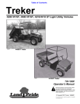
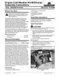
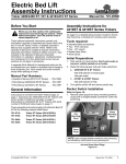
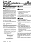
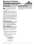
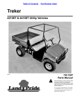
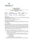
CVT And Cover Kit
Assembly Instructions
Manual No. 700-520M
Treker 4210/4410 ST Series
Before You Start
!
When you see this symbol, the subsequent
instructions and warnings are serious - follow
without exception. Your life and the lives of
others depend on it!
IMPORTANT: Before you begin, read these
instructions and check to be sure all parts and tools
are accounted for. Please retain these installation
instructions for future reference and parts ordering
information.
Your CVT And Cover Kit is exclusively designed for your
Land Pride 4210ST & 4410ST Trekers. Please read
these installation instructions and your vehicle
Operator’s Manual thoroughly before beginning.
Especially read information relating to safety concerns.
Also included in the Operator’s Manual is important
information on operation, adjustment, troubleshooting,
and maintenance for this kit (some manual sections do
not apply to all accessories).
A separate Parts Manual for replacement parts can be
purchased from your dealer or available free of charge at
www.landpride.com. Have model and serial numbers
handy when placing an order.
Manual Part Numbers:
• Operator’s Manual . . . . . . . . . . . . . . . . 700-108M
• Parts Manual . . . . . . . . . . . . . . . . . . . . . 700-109P
Further Assistance
Your dealer wants you to be satisfied with your new CVT
And Cover Kit. If for any reason you do not understand
any part of this manual or are not satisfied with the
service received, the following actions are suggested:
1. Discuss the matter with your dealership service
manager making sure he is aware of any problems
you may have and that he has had the opportunity to
assist you.
2. If you are still not satisfied, seek out the owner or
general manager of the dealership, explain the
problem and request assistance.
3. For further assistance write to:
Land Pride Service Department
1525 East North Street
P.O. Box 5060
Salina, Ks. 67402-5060
E-mail address
[email protected]
Assembly Instructions
A detailed listing of parts for this accessory kit is provided
on page 6. Use the list as a checklist to inventory parts
received. Please contact your local Land Pride dealer for
any missing hardware.
General Information
These assembly instructions apply to the following CVT
And Cover Kit Accessories listed below:
700-519A
Initial Preparations
The steps listed below must be followed before installing
this kit:
TREKER CVT/COVER KIT
Tools required:
• Safety glasses
• Work gloves
• Center punch
• Hammer
• Electric drill with 1/8" drill bit
• Extension cord (if required)
• Phillips screwdriver
• 3/16" hex socket wrench
• 11/32" box end or open end wrench
• 7/16" box end or open end wrench
• Two 1/2" box end or open end wrenches
• 9/16" box end or open end wrench
• 3/8" or 1/2" ratchet wrench with 3" extension
!
CAUTION
Securely support cargo box in the up position to prevent
injury when working under the cargo box.
1. Park vehicle on a level surface. Don’t work under or
around a vehicle parked on an incline.
2. Move gear shift lever to park, and chock front and
back of any wheel to prevent vehicle from rolling.
3. Raise cargo box fully up and securely support it in
the up position to prevent injury while working
around the engine.
4. Turn ignition switch off and remove switch key.
and 3/4" socket
• Pop Rivet Gun
• T-27 Torx driver
© Copyright 2007
Printed
3/20/07
1
Land Pride
Assembly Instructions
Left Side Panel Detachment
The fuse box on the left side panel can interfere with
removing and assembling the CVT enclosure. It is simpler
to detach the side panel from the frame than to detach the
fuse box.
Refer to Figure 1:
1. Remove five 1/4" hex flange lock nuts (#3) and 1/4"
Phillip head machine screws (#2). Allow the side
panel to hang from its wiring harness.
2. Lift side panel (#1) with fuse box and wiring harness
out of the way when removing and installing driveline
components that interfere.
2. Loosen hose clamp (#1B). Remove 1/4" Phillips
head self-tapping drive screws (#4), intake air hose
(#9) and snorkel (#8).
3. Remove twelve 1/4" x 3/4" Phillips head screws (#2)
and outer enclosure (#6).
Removal of Exhaust Heat Shield
Refer to Figure 2:
1. Remove existing #8 x 1/2" hex screws (#3) and
exhaust heat shield (#5). Save for reattachment.
Removal of Air Hoses & Outer Enclosure
The following removed components will not be reused in
assembly of the new CVT drive.
Refer to Figure 2:
1. Loosen hose clamp (#1A) and remove exhaust air
hose (#7).
22416
Side Panel Removal
Figure 1
CVT Venting Removal
Figure 2
2
Manual No. 700-520M
■
3/20/07
Land Pride
Assembly Instructions
Removal of Pulleys & Inner Enclosure
The following removed components will not be reused in
assembly of the new CVT drive.
Refer to Figure 3:
1. Remove 3/8" x 3 1/2" hex bolt (#7), lock washer (#9)
and CVT adapter (#17) from CVT drive pulley (#15).
2. Remove 1/2" x 2" hex bolt (#5), lock washer (#10)
and flat washer (#11) from CVT driven pulley (#16).
IMPORTANT: Pulley flanges will bend and nick easily
if handled roughly. Always handle pulleys gently to
prevent damage.
3. Remove CVT pulleys (#15 & #16) and CVT belt
(#14).
4. Remove CVT spacer (#1), shims (#19) and
3/16" x 1/4" x 2 1/2" key (#3) from engine drive shaft.
5. Remove 3/16" sq. x 3" long key (#2) from trans-axle
driven shaft.
6. Remove 5/16" x 3/4" hex socket screws (#4),
5/16" x 1" hex head bolts (#6), neoprene plated
washers (#12) and flanged lock nuts (#8).
7. Remove inner enclosure (#18) and gasket (#13).
Pulley and belt Removal
Figure 3
3/20/07
■
Manual No. 700-520M
3
Land Pride
Assembly Instructions
CVT Inner Enclosure Installation
Refer to Figure 4:
1. Loosen engine mounting hardware.
NOTE: Clutch alignment tool (P/N 790-001A) may
be purchased from your nearest Land Pride Dealer.
2. Use clutch alignment tool to adjust engine shaft
shoulder to offset 1.937" (1 15/16") out farther than
trans-axle shaft shoulder. Add shims as needed to
finalize offset distance.
3. Make a dry run by installing pulleys and belt with no
keys or shims.
a. Mount drive pulley (#17) onto the engine drive
shaft.
b. Hang belt (#16) on drive pulley (#17).
c. Install belt (#16) on driven pulley (#18) and slide
pulley onto trans-axle driven shaft.
d. Push both pulleys with installed belt back until
they stop. Check belt alignment to make sure it is
straight and aligned.
e. Add or remove shims from engine shaft if
required.
NOTE: A thin layer of silicon can be added to the
gasket to hold it against the engine block and in
alignment with mounting holes.
4. Install gasket (#15) over engine drive shaft. Make
certain gasket holes are in alignment with mounting
holes on engine block.
5. Place CVT inner enclosure (#2) over trans-axle
driven shaft and engine driven shaft.
6. Secure enclosure to engine block with four
5/16" x 1 1/4" hex socket screws (#5) with loctite
applied to threads. Draw hex socket screws up snug;
do not tighten.
IMPORTANT: Neoprene on washers (#14) in step 7 is
placed against the inner enclosure.
7. Secure CVT inner enclosure to trans-axle shaft with
four 5/16"-18 x 1" GR5 hex bolts (#7), neoprene
plated washers (#14) and hex lock nuts (#9). Draw
nuts up snug; do not tighten.
8. Center CVT inner enclosure over trans-axle driven
shaft. Make sure enclosure clears axle shaft and
tighten lock nuts (#9) to 17 ft.lbs. of torque.
9. Tighten hex socket screws (#5) to 20 to 25 in-lbs. of
torque.
Inner CVT Shield, Pulleys & Belt Installation
Figure 4
4
Manual No. 700-520M
■
3/20/07
Land Pride
Assembly Instructions
Assembly of CVT Pulley and Belt
Refer to Figure 4:
IMPORTANT: Pulley flanges will bend and nick easily
if handled roughly. Always handle pulleys gently to
prevent damage.
1. Make a dry run by installing driven pulley (#18) onto
trans-axle input shaft until it stops and then spin
pulley by hand to verify it does not catch on any
objects while rotating. Remove pulley.
2. Make certain shims in step 3e on page 4 are still on
the engine shaft.
3. Apply anti-seize to engine drive shaft and install
3/16" x 1/4" x 2 1/4" long key (#4).
4. Slide drive pulley (#17) onto engine drive shaft and
hang belt (#16) on drive pulley (#17).
5. Apply anti-seize to trans-axle input shaft and Install
3/16" sq. x 3" long key (#3).
6. Install belt (#16) on driven pulley (#18) and slide
pulley onto trans-axle driven shaft.
7. Push both pulleys with installed belt back until they
stop. Recheck belt alignment.
8. Secure drive pulley (#17) with 3/8"-24 x 6 1/2" GR5
hex bolt (#8), 3/8" lock washer (#11) and flat
washer (#10). Torque hex bolt to 35 ft. lbs.
9. Secure driven pulley (#18) with 1/2"-20 x 1 3/4" hex
bolt (#6), 1/2" lock washer (#12) and 1/2" flat
washer (#13). Torque hex bolt to 85 ft. lbs.
and secure with twelve 1/4"-20 x 3/4" screws (#4). Do
not tighten until all screws are installed. Tighten each
screw to 5.6 ft-lbs. of torque.
2. Install drain cap (#6) over drain nozzle and secure
with 1" spring clamp (#3).
3. Install CVT diverter outlet (#8) to outer enclosure
with two 3/16” pop rivets (#2).
4. Install exhaust heat shield (#10) to exhaust pipe.
Secure with existing #8 x 1/2” hex screws (#5) and
tighten.
Assembly of CVT Venting
Refer to Figure 6:
1. Slip worm drive hose clamp (#2A) over bottom end of
air intake hose (#6). Do not tighten. Install air intake
hose over CVT inner enclosure opening (#1).
1. Slip second worm drive hose clamp (#2B) over top
end of air intake hose (#6). Do not tighten.
2. Insert snorkel (#4) into open end of air intake
hose (#6) and position snorkel on top of Treker
firewall panel as shown.
3. Mark hole locations for mounting snorkel and pre drill
two 1/8" diameter holes in fire wall panel flange.
4. Secure snorkel to firewall panel by driving two
#10 x 3/4” hex head self-tapping drive screws (#4)
into the panel’s flange.
5. Position worm drive clamps (#2A & #2B)
approximately 1/8" from each end of air intake hose
and tighten.
6. Insert air intake filter (#5) into snorkel (#4).
CVT Venting Installation
Figure 6
Final Assembly
Outer CVT Enclosure Installation
Figure 5
Assembly of CVT Outer Enclosure
Refer to Figure 5:
1. Being careful not to scratch gasket edge of outer
enclosure (#7), mate enclosure with inner enclosure
3/20/07
■
Refer to Figure 1 on page 2:
1. Reattach side panel (#1) with five 1/4” Phillip head
machine screws (#2) and 1/4” hex flange lock nuts
(#3). Tighten lock nuts to 6 ft. lbs. of torque.
2. Remove blocking supporting Treker bed in the up
position and lower the bed.
Manual No. 700-520M
5
Kit No. 700-519A
Treker CVT/Cover Kit
Qty.
Part No.
Part Description
1
1
1
1
2
1
1
1
12
2
4
1
4
1
4
1
1
1
1
1
1
1
1
1
1
1
1
1
1
1
700-112A
700-503S
700-520M
710-097D
800-219C
800-235C
800-259C
800-350C
801-180C
801-199C
801-215C
802-329C
802-738C
802-823C
803-177C
804-012C
804-013C
804-015C
804-016C
804-135C
816-470C
816-546C
817-621C
817-711C
817-712C
826-523C
826-525C
840-266C
840-268C
840-323C
CVT SHIM KIT TREKER / ATR
ASSEMBLY, CVT INNER COVER
CVT/COVER UPDATE MANUAL
KEY 3/16" x 3"
RIVET POP 3/16" .251"-.375" LF
SPRING CLAMP 1" OD HOSE
CLAMP WORM DRIVE #36SS (1.81-2.75)
KEY .187" x .247" x 2.25" LG
TTHMS 1/4"-20 x 3/4"
SCR SELF TAP #10 x 3/4"
HSFHCS 5/16"-24 x 1 1/4", BLK
HHCS 1/2"-20 x 1 3/4" GR5
HHCS 5/16"-18 x 1" GR5 YELLOW DIE
HHCS 3/8" -24 x 6 1/2" GR5 PLT
NUT HEX FLG TOP LK 5/16" -18 YLW
WASHER FLAT 3/8" SAE PLT
WASHER LOCK SPRING 3/8" PLT
WASHER LOCK SPRING 1/2" PLT
WASHER FLAT 1/2" SAE PLT
WASHER FLAT 5/16" NEOPRENE PLT
SEAL, CVT TO ENGINE
BELT, CVT -LP3
CAP, DRAIN 7/8" OD PORT
ENCLOSURE, CVT OUTER
OUTLET DIVERTER, CVT
DRIVER, POWERBLOCK - LP3
DRIVEN, CVTECH POWERBLOCK-LP3
SNORKEL AIR INTAKE
FILTER, AIR INTAKE
HOSE, CVT AIR INTAKE
Corporate Office: P.O. Box 5060
Salina, Kansas 67402-5060 USA
www.landpride.com